AAW-24CM3FHUE - Air-conditioner Admiral - Free user manual and instructions
Find the device manual for free AAW-24CM3FHUE Admiral in PDF.


| Product Type | Window Air Conditioner |
| Model | AAW-24CM3FHUE |
| Brand | Admiral |
| Cooling Capacity | 24000 BTU |
| Energy Efficiency Ratio (EER) | 10.5 |
| Voltage | 230V / 60Hz |
| Current | 12.5A |
| Power Consumption | 2200W |
| Air Flow | 400 CFM |
| Dimensions (W x H x D) | 26.0 x 27.4 x 17.6 inches |
| Weight | 85 lbs |
| Refrigerant | R-32 |
| Noise Level | 56 dB |
| Thermostat | Yes |
| Remote Control | Yes |
| Filter Type | Washable |
| Installation Kit Included | Yes |
| Window Width | 26 - 42 inches |
| Window Height | 13 - 15 inches |
| Energy Star | Yes |
| Warranty | 1 year parts and labor |
| Color | White |
Frequently Asked Questions - AAW-24CM3FHUE Admiral
User questions about AAW-24CM3FHUE Admiral
0 question about this device. Answer the ones you know or ask your own.
Ask a new question about this device
Download the instructions for your Air-conditioner in PDF format for free! Find your manual AAW-24CM3FHUE - Admiral and take your electronic device back in hand. On this page are published all the documents necessary for the use of your device. AAW-24CM3FHUE by Admiral.
USER MANUAL AAW-24CM3FHUE Admiral
natural_image
Front view of a white air conditioner unit with ventilation grilles and control panel (no visible text or symbols)Remote control
AAW-08CR1FHUE
AAW-10CR1FHUE
AAW-12CR1FHUE
AAW-15CR1FHUE
AAW-18CR3FHUE
AAW-22CR3FHUE
AAW-24CR3FHUE
Mechanical control
AAW-08CM1FHUE
AAW-10CM1FHUE
AAW-12CM1FHUE
AAW-15CM1FHUE
AAW-18CM3FHUE
AAW-22CM3FHUE
AAW-24CM3FHUE
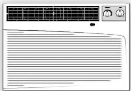
natural_image
Front view of an air conditioner unit with a solar panel and control panel (no text or symbols visible)Thank you for purchasing an Admiral ^b room air conditioner. Please read this “Use and Care Manual” carefully before installing and using this appliance. Keep this manual for future reference.
Parts Identification 2-3
Air Conditioner Safety 4-5
Electrical Specifications 6
Tips Before Installation 7
Installation Instructions 8-12
Operating Instructions 13-16
Care and Maintenance 17
Trouble Shooting Guide 18
Warranty 19
ÍNDICE
Page
Introducción 20
Thank you for choosing this room air conditioner to cool your home. This USE AND CARE MANUAL provides information necessary for the proper care and maintenance of your new room air conditioner. If properly maintained, your air conditioner will give you many years of trouble free operation. To avoid installation difficulties, read instructions completely before starting. This manual contains information for the installation and operation of your room air conditioner.
PART IDENTIFICATION
▶ Mechanical control model
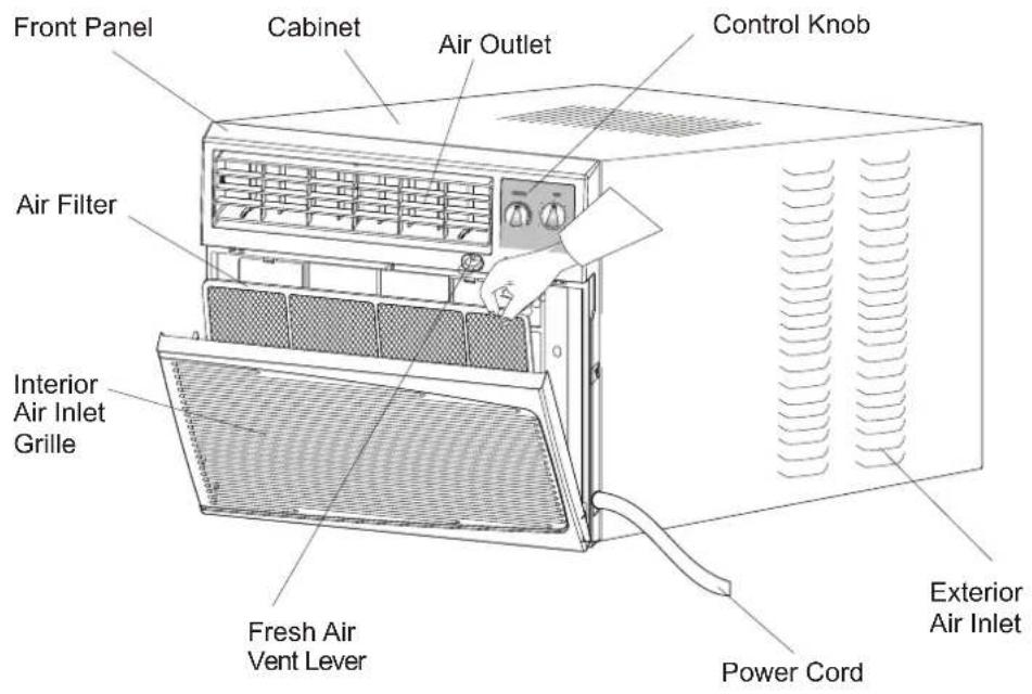
text_image
Front Panel Cabinet Air Outlet Control Knob Air Filter Interior Air Inlet Grille Fresh Air Vent Lever Power Cord Exterior Air InletNote:
The figures in this manual are based on the external view of a standard model. Consequently, the shape may differ from that of the air conditioner you have selected.
INTRODUCTION
PART IDENTIFICATION
▶ Remote control model
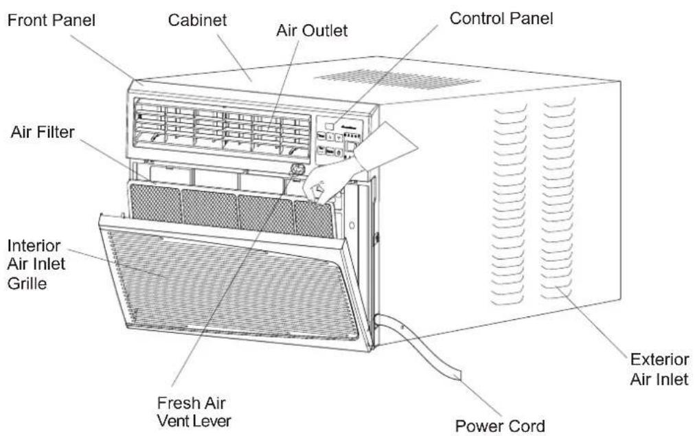
text_image
Front Panel Cabinet Air Outlet Control Panel Air Filter Interior Air Inlet Grille Fresh Air Vent Lever Power Cord Exterior Air InletControl Panel
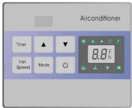
text_image
Airconditioner Time ▲ ▼ Fan Speed Mode 8.8°F hRemote Control
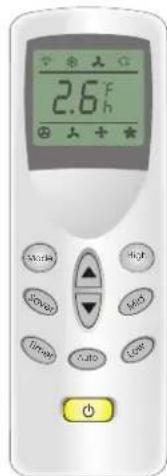
text_image
2.6°F Start High Low Mid Time Auto Cost ResetNote:
The figures in this manual are based on the external view of a standard model.
Consequently, the shape may differ from that of the air conditioner you have selected.
AIR CONDITIONER SAFETY
Your safety and the safety of others are very important.
We have provided many important safety messages in this manual and on your appliance. Always read and obey all safety messages.

This is the SAFETY ALERT SYMBOL.
This symbol alerts you to potential hazards that can kill or hurt you and others.
All safety messages will follow the safety alert symbol and either the word “DANGER” or “WARNING.” These words mean:

text_image
DANGERYou can be killed or seriously injured if you don't immediately follow instructions.

text_image
WARNINGYou can be killed or seriously injured if you don't follow instructions.
All safety messages will tell you what the potential hazard is, tell you how to reduce the chance of injury, and tell you what can happen if the instructions are not followed.
IMPORTANT SAFETY INSTRUCTIONS
WARNING: To reduce the risk of fire, electrical shock, or injury when using your air conditioner, follow these basic precautions:
- Plug into a grounded 3-prong outlet. • Do not use an extension cord.
- Do not remove ground prong. • Unplug air conditioning before servicing.
- Do not use an adapter. Use two or more people to move and install air conditioner.
— S A V E THESE INSTRUCTIONS —
INSTALLATION REQUIREMENTS
- The air conditioner should be connected to the appropriate electrical receptacle as shown in the chart on Page 6 (Receptacle and Fuse Types).
- The use of a time-delay fuse or time-delay circuit breaker is recommended.
- All wiring must comply with local and national electrical codes and be installed by a qualified electrician. If you have any questions, contact a qualified electrician.
Electrical Requirements
WARNING

ELECTRIC SHOCK HAZARD
- Plug into a grounded 3-prong outlet.
- Do not remove ground prong.
- Do not use an adapter.
- Do not use an extension cord.
- Failure to follow these instructions can result in death, fire, or electrical shock.
Power Supply Cord
NOTE: Your unit's device may differ from the one shown.
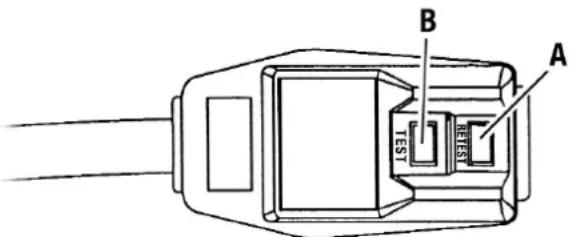
text_image
A B TEST RETESTA Reset Button B Test Button
This room air conditioner is equipped with a power supply cord required by UL. This power supply cord contains state-of-the-art electronics that sense leakage current. If the cord is crushed, the electronics detect leakage current and power will be disconnected in a fraction of a second.
To test your power supply cord:
- Plug power supply cord into a grounded 3-prong outlet.
- Press RESET.
- Press TEST (listen for click; Reset button will trip and pop out).
- Press and release RESET (listen for click; Reset button will latch and remain in). The power supply cord is ready for operation.
NOTES:
- The Reset button must be pushed in for proper operation.
- The power supply cord must be replaced if it fails to trip when the test button is pressed or fails to rest.
- Do not use the power supply cord as as an off/on switch. The power supply cord is designed as a protective device.
- A damaged power supply cord must be replaced with a new power supply cord obtained from the product manufacturer and must not be repaired.
- The power supply cord contains no use serviceable parts. Opening the tamper-resistant case voids all warranty and performance claims.
INSTALLATION INSTRUCTIONS
Unpack the Air Conditioner
WARNING
EXCESSIVE WEIGHT HAZARD
Use two or more people to move and install air conditioner.
Failure to do so can result in back or other injury.
Remove packaging materials
- Remove and properly dispose of packaging materials. Remove tape and glue residue from surfaces before turning on the air conditioner. Rub a small amount of liquid dish soap over the adhesive with your fingers. Wipe with warm water and dry.
- Do not use sharp instruments, rubbing alcohol, flammable fluids, or abrasive cleaners to remove tape or glue. These products can damage the surface of your air conditioner.
- Handle air conditioner with care.
ELECTRICAL SPECIFICATIONS
-
All wiring must comply with local and national electrical codes and must be installed by a licensed electrician. If you have any questions regarding the following instructions, contact a licensed electrician.
-
Check available power supply and resolve any wiring problems BEFORE installing and operating this unit.
-
For your safety and protection, this unit is grounded through the power cord when plugged into a matching wall outlet. If you are not sure whether your wall outlet is properly grounded, please consult a licensed electrician.
-
The wall outlet (3-pin) must match the plug (3-pin) on the power cord supplied with the unit. DO NOT use plug adapters or extension cords. See (Table 1) for receptacle and fuse information.
-
The rating plate on the unit contains electrical and other technical data. The rating plate is located on the front of the base pan. Make sure to use the correct power supply according to the rating plate of your air conditioner.

Electric Shock Hazard

If the air conditioner has a serial plate rating of 115 volts and up to and including 7.5 amps, the unit maybe on a fuse or circuit breaker with other devices. However, the maximum amps on all devices for that fuse or circuit breaker can not exceed the amps of the fuse for the circuit breaker.
If the air conditioner has a serial plate rating of 115 volts and greater than 7.5 amps it must have its own fuse or circuit breaker, and no other device or unit should be operated on the fuse or circuit breaker.
If the air conditioner has a serial plate rating of 230 volts, it must have its own fuse or circuit breaker, and no other device or unit should be operated on the fuse or circuit breaker.
To avoid the possibility of personal injury, disconnect power to the unit before installing or servicing.
RECEPTACLE AND FUSE TYPES
| COOLING CAPACITY | 8K-15K | 18K | 22K-24K |
| RATED VOLTS | 125 | 250 | 250 |
| AMPS | 15 | 15 | 20 |
| WALL OUTLET |  |  |  |
| FUSE SIZE | 15 | 15 | 20 |
Note:8K-15K including AAW-08CM1FHUE AAW-08CR1FHUE
AAW-10CM1FHUE AAW-10CR1FHUE
AAW-12CM1FHUE AAW-12CR1FHUE
AAW-15CM1FHUE AAW-15CR1FHUE
18K including AAW-18CR3FHUE AAW-18CM3FHUE
22K-24K including AAW-22CR3FHUE AAW-22CM3FHUE
AAW-24CR3FHUE AAW-24CM3FHUE
Table 1
TIPS BEFORE INSTALLATION
Your Room Air Conditioner unit is designed to be highly efficient and save energy. Follow these recommendations for greater efficiency.
- Select thermostat setting that suits your comfort needs and leave the thermostat at that chosen setting.
- The air filter is very efficient in removing airborne particles. Keep the air filter clean. Typically, the filter should be cleaned once a month. More frequent cleaning may be necessary depending on outdoor and indoor air quality.
- Use drapes, curtains, or shades to keep direct sunlight from heating your room, but DO NOT obstruct the air conditioner. Allow air to circulate around the unit without obstructions.
- Start your air conditioner before outdoor air becomes hot/cold and uncomfortable. This avoids an initial period of discomfort while the unit is cooling or heating off the room.
- When outdoor temperature is cool enough, use HIGH or LOW FAN only. This circulates indoor air, providing some cooling comfort, and utilizes less electricity than when operating on a cooling setting.
Your Room Air Conditioner was designed for easy installation in a single or double-hung window. NOTE: This unit is NOT designed for vertical (slider type) windows.
CAUTION
To avoid installation/operating difficulties, read the instructions thoroughly.
NOTE: Save the shipping carton and packing materials for future storage or transport of the unit. Please check the contents of the hardware kit against the corresponding model check list, prior to installation of the unit.
See lists below.(Fig.A)
Fig. A Installation Hardware
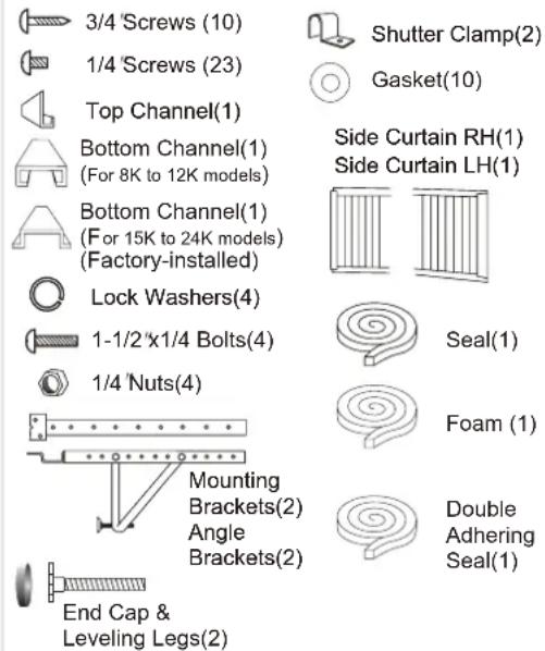
text_image
3/4 Screws (10) 1/4 Screws (23) Top Channel(1) Bottom Channel(1) (For 8K to 12K models) Bottom Channel(1) (For 15K to 24K models) (Factory-installed) Lock Washers(4) 1-1/2"x1/4 Bolts(4) 1/4 Nuts(4) Mounting Brackets(2) Angle Brackets(2) End Cap & Leveling Legs(2) Shutter Clamp(2) Gasket(10) Side Curtain RH(1) Side Curtain LH(1) Seal(1) Foam (1) Double Adhering Seal(1)NOTE: Surplus screw(s) for spare use.
Tools Needed for Window Installation
Screw drivers: Both Philips and flat head
Power drill: 1/8 inch diameter drill bit
Pencil
Measuring tape
Scissors
Carpenters level
INSTALLATION INSTRUCTIONS
CAUTION
Because the compressor is located on the controls side of the unit (right side), this side will be heavier and more awkward to manipulate. Inadequate support on control side of the unit can result in personal injury and damage to your unit and property. Therefore, it is recommended to have someone assist you during the installation of this unit.
1. Select the Best Location
A. Your room air conditioner was designed to fit easily into a single or double hung window. However, since window designs vary, it may be necessary to make some modifications for safe and proper installation.
B. Make sure window and frame is structurally sound and free from dry and rotted wood.
C. For maximum efficiency, install the air conditioner on side of the house or building which favors more shade than sunlight. If the unit is in direct sunlight, it is advisable to provide an awning over the unit.
D. Provide sufficient clearance around the cabinet to allow for ample air circulation through the unit. See (Fig.B). The rear of the unit should be outdoors and not in a garage nor inside of a building. Keep unit as far away as possible from obstacles and obstructions and at least 30" above the floor or ground. Curtains and other objects within a room should be prevented from blocking the air flow.
Window opening requirements (see table below)
| Size\Model | 8K-10K | 12K | 15-24K |
| Cabinet size (W*H*D) | 20.5" *14.8" *23.1" | 22.8" *15.7" *24.1" | 26.5" *18.5" *26.9" |
| Min. Window opening | 24" | 27" | 30" |
| Max. Window opening | 38" | 41" | 44" |
E. Be certain the proper electrical outlet is within reach of the installation. Use only a single outlet circuit rated at proper current (see table 1 on page 4). All wiring should be in accordance with local and national electrical codes.
F. Your unit was designed to evaporate condensation under normal conditions. However, under extreme humidity conditions, excess condensation may cause the basepan to overflow to the outside.
The unit should be installed where condensation run-off cannot drip on pedestrians or neighboring properties.
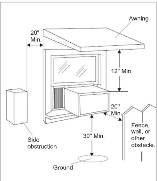
text_image
20" Min. 12" Min. 20" Min. 30" Min. Fence, wall, or other obstacle. Ground Side obstructionFig.B
INSTALLATION INSTRUCTIONS
2. Preparation to Remove the Air Conditioner Slide-Out Chassis
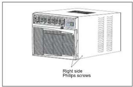
A. Remove total of (4) Philips screws securing the chassis to the cabinet. There are (2) screws on each side. The set of screws closest to the front of the unit secure the front panel to the cabinet. The set of screw closest to the rear of the unit secure the cabinet to the chassis. See (Fig. 1).
B. Remove the front panel assembly from the cabinet by gently pulling it.
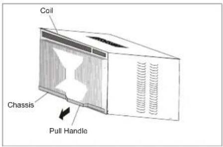
C. Grasp the pull handle at the front of the slide-out chassis and carefully slide the air conditioner out of the cabinet. See (Fig. 2).
Please seek assistance for this procedure.
Note: Screws must be reinstalled upon completion of the window installation to secure slide-out chassis.
3. Assembly of the upper & lower channels to the cabinet
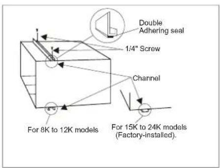
A. "L" Shaped Top Channel: Stick the double adhering seal to the "L" shaped top channel, and then Install the "L" shaped top channel to the cabinet as shown in (Fig. 3) using (5) 1/4" screws. B. "n" Shaped Bottom Channel installed as shown in (Fig. 3) using (4) 1/4" screws.
NOTE: For 15K to 24K models, the bottom channel has been factory- installed, and their shapes may differ from the others, but their functions are similar.
4. Assembly of the side shutters (curtains) to the cabinet.
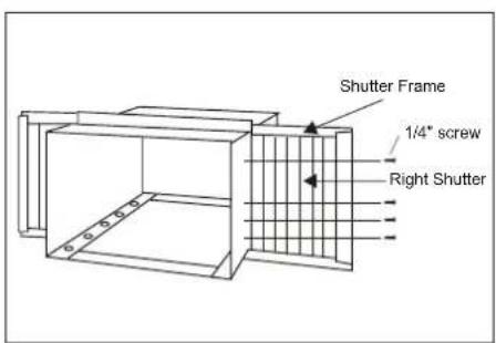
Slide the shutters into the top and bottom channels as shown in (Fig. 4). The shutters are identified (on each frame) as "left" & "right". Attach the shutters to the cabinet using (4) 1/4" screws on each side.
text_image
Right side Philips screwsFig. 1
text_image
Coil Chassis Pull HandleFig. 2
text_image
Double Adhering seal 1/4" Screw Channel For 8K to 12K models For 15K to 24K models (Factory-installed).Fig. 3
text_image
Shutter Frame 1/4" screw Right ShutterFig. 4
INSTALLATION INSTRUCTIONS
5. Installation of Mounting Brackets and First Sealing Strip
NOTE: Windows come in a variety of different styles. Therefore, it may be necessary to modify or improve your particular installation.
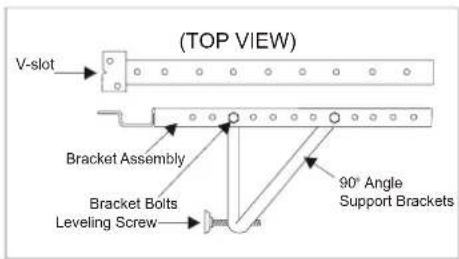
A. Attach the bracket assembly to 90 angle support brackets (Fig. 5) using (2) 1 1/2" bolts
Two bolts per bracket. Secure with the (2)
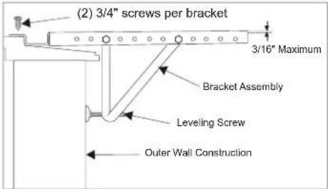
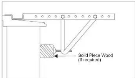
1/4" lock washers and (2) 1/4" nuts. DO NOT immediately tighten these bolts as it may be necessary to adjust the depth of the bracket assembly, depending on the depth of your window sill. See (Fig. 7). Install the two leveling screws into the 90° support brackets. Test the bracket assembly in the window before cabinet installation. If the leveling screws are distanced too far away from the wall to provide stability, it may be necessary for you to fill this area with a solid piece of wood. See (Fig. 8).
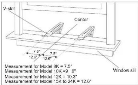
B. Measure the inside window sill width and find the center as shown in (Fig. 6). Align the V-slot in each bracket on these marks and mount the brackets to the sill using 3/4" screws provided. Brackets should be perpendicular to the inside window sill. See (Fig. 6).
C. For proper condensation run-off it will be necessary to adjust the angle/pitch of the window brackets. This is accomplished by adjusting the distance of the leveling screw on the outer wall. The maximum angle/pitch should not exceed more than 3/16". See (Fig.7).
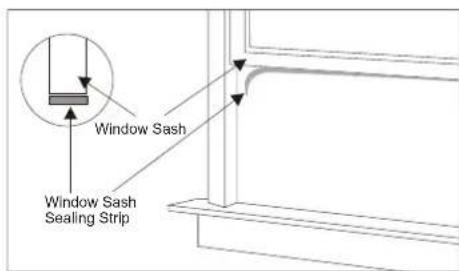
D. Cut the seal strip to fit the underside of the bottom window sash. Remove the peel-off backing on the seal and attach it to this sash. See (Fig. 9).
CAUTION
Use a solid piece of wood to provide stability. This will be required when sills are extra deep. See (Fig. 8).
text_image
(TOP VIEW) V-slot Bracket Assembly Bracket Bolts Leveling Screw 90° Angle Support BracketsFig. 5
text_image
V-slot Center 7.5" 12.6" 7.5" 12.6" Window sill Measurement for Model 8K = 7.5" Measurement for Model 10K =9 .6" Measurement for Model 12K = 10.3" Measurement for Model 15K to 24K = 12.6"Fig. 6
text_image
(2) 3/4" screws per bracket 3/16" Maximum Bracket Assembly Leveling Screw Outer Wall ConstructionFig. 7
text_image
Solid Piece Wood (If required)Fig. 8
text_image
Window Sash Window Sash Sealing StripFig. 9
INSTALLATION INSTRUCTIONS
6. Installation of the cabinet
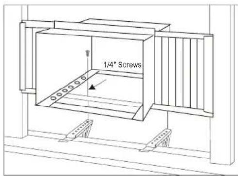
A. Align one hole in the bottom of the cabinet with one hole in the bracket assembly. Secure the cabinet to the bracket using (3) 1/4" screws provided. Repeat the same procedure on the opposite side of the cabinet. See (Fig. 10).
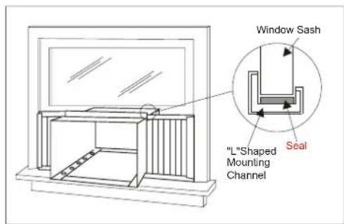
B. Ensure the "L" shaped mounting channel is positioned in front of the sash. The "U" shaped bottom channel of the cabinet should be positioned in the track provided on the bracket assembly. Pull the window down until it rests just behind the front of the "L" shaped mounting channel. See (Fig. 11).
C. Check to make sure that the cabinet is slanted slightly downward on the outside. If necessary, re-adjust support bracket as shown in (Fig. 7).
7. Secure Shutters
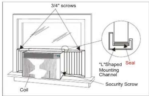
A. Carefully slide the air conditioner back into the cabinet.(Please seek assistance for this procedure). B. Reinstall the slide-out-chassis security screws (removed earlier) on both sides of the cabinet. See (Fig. 12).
Secure the top of the frames to the window sash with (2) 3/4" screws. C. Now, secure bottom frame of shutters using one shutter clamp and one 3/4" screw on each side(Fig. 1
8. Reinstalling Front Panel Assembly
A. Position the front panel on the cabinet starting at the top. The front panel lock tabs must be inserted into the retaining slots in the cabinet. Repeat this procedure on all sides. B. Secure the front grille to the cabinet using the Philips screws removed earlier(Fig. 1).
text_image
1/4" ScrewsFig. 10
text_image
"L"Shaped Mounting Channel Window Sash SealFig. 11
text_image
3/4" screws Coil "L"Shaped Mounting Channel Security Screw SealFig. 12
INSTALLATION INSTRUCTIONS
9. Complete the installation
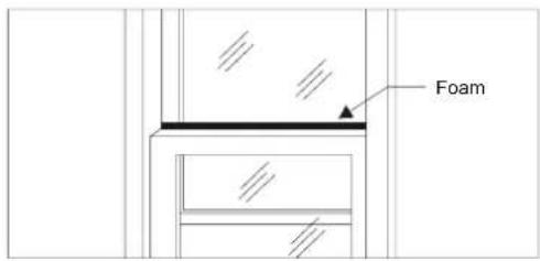
A. Cut the foam to fit the opening between the top of the inside and outside window. See (Fig. 13).
B. Some installations may require additional sealing around the window and air conditioner. Check for any air leaks and seal where necessary.
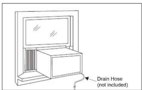
C. In very humid areas, the water removal may be excessive enough to overflow the unit or increase the noise of the air conditioner. If this occurs, you may wish to attach a drain hose (not included) to the drain plug allowing condensations to run off conveniently. See (Fig. 14).
text_image
FoamFig. 13
text_image
Drain Hose (not included)Fig. 14
OPERATING INSTRUCTIONS
MECHANICAL CONTROL MODEL
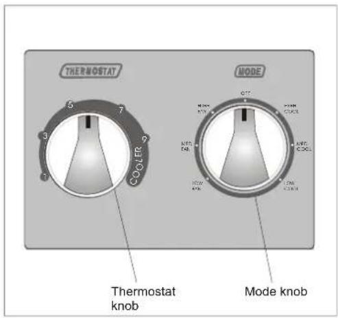
MODE
The mode knob controls fan speeds and cooling speeds. To set desired cooling temperature, simply rotate the mode knob dial to the appropriate setting.
THERMOSTAT
The thermostat automatically controls the cooling cycle (compressor) of the air conditioner to maintain room temperature. However, the fan motor will continue to operate after the compressor (cooling cycle) is completed.
LOW FAN will circulate the air at a minimum speed without cooling.
MED FAN will circulate the air at a middle speed without cooling.
HIGH FAN will circulate the air at a maximum speed without cooling.
LOW COOL provides cooling, automatically with minimum air circulation. Recommended for nighttime use.
MED COOL provides cooling, automatically with middle air circulation. Recommended for night-time use.
HIGH COOL provides cooling, automatically with quick cooling or for extremely hot days. Once room is cooled, reduce setting to LOW COOL.
OFF will completely shut-off the unit.
NOTE: After setting the mode, allow 3 minutes before switching to another mode.
Fresh Air Ventilation is usually kept in the closed position. Use only when clearing smoke and/or odors from the room. Pull to open.
text_image
THERMOSTAT COOLER 5 7 3 7 1 MODE QTT MTRR KRCR KRTC COCK NTRW AUR LTRW LTRW Thermostat knob Mode knobFig. 15
text_image
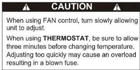
CAUTION When using FAN control, turn slowly allowing unit to adjust. When using THERMOSTAT, be sure to allow three minutes before changing temperature. Adjusting too quickly may cause an overload resulting in a blown fuse.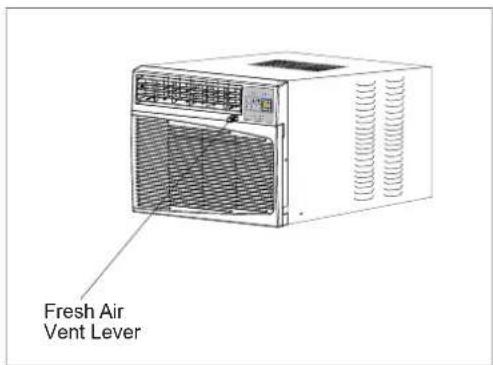
text_image
Fresh Air Vent LeverFig. 16
OPERATING INSTRUCTIONS
▶ELECTRONIC CONTROL PANEL MODEL
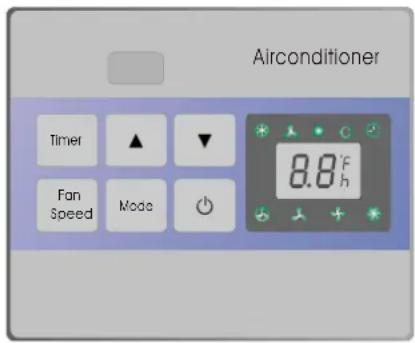
You can easily operate this air conditioner by pressing relevant button on the control panel as well as the remote control.

Button
The air conditioner will be started when it is energized or will be stopped when it is in operation, if you press this button.
Mode button
Each time Mode button is pressed, the operation mode is changed in sequence:
COOLING FAN ONLY ENERGY SAVING COOLING
NOTE: After setting the mode, allow three (3) minutes before switching to another mode. In the FAN ONLY Mode, Room Temperature display range is from 0°C (32°F) to 38°C (99°F). Room Temperature below 32°F, the Temperature display L0. Room Temperature above 99°F, the Temperature display H1.
Fan Speed button
Used to select fan speed in sequence auto, low, medium and high.
Timer button
Used to set or cancel timer operation.
When the unit is in operation, you can set OFF TIMER. When the unit is off, you can set ON TIMER. Timer setting range is 0 to 24 hours.
If the OFF TIMER is set, the time LED displays the remaining time to turn off the unit for only 12 seconds, then LED shifts to display set temperature. If you press TIMER button within the 12 seconds, OFF TIMER will be cancelled.
If the ON TIMER is set, the timer LED displays the remaining time to turn on the unit. If you want to cancel ON TIMER, press TIMER button.
▲▼ Button
Used to set room temperature in COOLING mode or used to set time in TIMER mode. If the two keys are pressed at the same time, the temperature LED display will alternate between ^ C and ^ F.
NOTE: Temperature setting range is from 19°C (66°F) to 31°C (88°F).
Control Panel
text_image
Airconditioner Timer ▲ ▼ Fan Speed Mode 8.8°F hIndication symbols of LED on control panel :
LED on control panel lights on when the relevant mode is in used.
OPERATING INSTRUCTIONS
Remote control
text_image
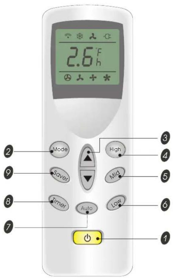
2.6°F h Mode Saver Timer Auto High Mid Low 1 2 3 4 5 6 71 ⏻ BUTTON
The appliance will be started when it is energized or will be stopped when it is in operation, if you press this button.
2 Mode BUTTON
Used to select the operation mode.
Each time the Mode button is pressed, the operation mode is changed in sequence:

3 ▲▼ BUTTONS
Used to set room temperature in COOLING mode or used to set time in TIMER mode. Temperature setting range is from from 19°C (66°F) to 31°C (88°F).
4 High BUTTON
Used to select the mode.high fan speed
5 Mid BUTTON
Used to select the Mid mode.fan speed
6 Low BUTTON
Used to select the Low mode.fan speed
7 Auto BUTTON
Used to select the Auto mode. fan speed
8 Timer BUTTON
Used to set or cancel timer operation.
9 Saver BUTTON
Used to select the mode.Energy-saving
Indication symbols of LCD on remote control:
Signal transmit
Cooling
Fan only
Energy-saving

Display set temp Display set timer
Auto fan speed
Low fan speed
+ Medium fan speed
* High fan speed
The Above symbols are shown when the relevant mode is in use.
- When Changing modes during operation, sometimes the unit does not always respond at once. Wait 3 minutes. - Wait 3 minutes before restarting the appliance.
OPERATING INSTRUCTIONS
Remote control
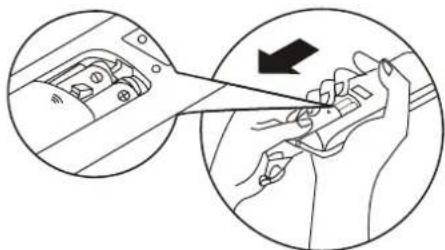
• How to Insert the Batteries
Remove the battery cover according to the arrow direction. Insert new batteries making sure that the (+) and (-) of battery are matched correctly.
Reattach the cover by sliding it back into position.
Note:
- Use 2 LR03 AAA (1.5volt) batteries. Do not use rechargeable batteries. Replace batteries with new ones of the same type when the display becomes dim.
- If the replacement is done within 1 minute, the remote control will keep original presetting.
• How to Use
To operate the room air conditioner, aim the remote control to the signal receptor. The remote control will operate the air conditioner at a distance of up to 23 feet when pointing at signal receptor of indoor unit.
• Remote Control Presetting
The remote control is NOT preset as Cooling only or Heat Pump by manufacturer.
Each time after the remote control replaces batteries or is energized, the Cooling indicator and Heating indicator will flashes alternately on LCD of the remote control.
User can preset the remote control type depending on the air conditioner type you have purchased as follows:
Press any button when* flashes, Heat Pump will be set.
Press any button when ✉ flashes, Cooling Only will be set.
If you don not press any button within 12 seconds, the remote control will be set as Heat Pump automatically.
• Back-light function(optional)
Hold down any button of remote control for about 2 seconds, back-light turns on. Release the button, it lights off automatically 10 seconds later.
natural_image
Diagram showing a hand holding a tool inside a vehicle's dashboard, with an inset close-up of the dashboard (no text or symbols present)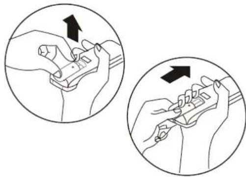
natural_image
Illustration showing two hands performing a manual tool manipulation technique (no text or symbols present)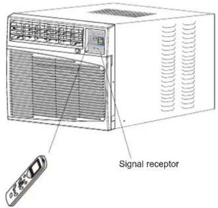
text_image
Signal receptorCARE AND MAINTENANCE
When servicing the air conditioner, be sure to turn the mode switch to the "OFF" position and disconnect the power cord from the electrical outlet.
- DO NOT use gasoline, benzine, thinner or other chemicals on the air conditioner as these substances may cause damage to the paint finish and deformation of plastic parts.
- Never attempt to pour water directly in front of the unit as this will cause deterioration of the electrical insulation.
Cleaning the Air Filter
Removal of Air Filter
If the air filter becomes clogged with dust, air-flow is obstructed and reduces efficiency. The air filter should be cleaned once a month. More frequent cleaning may be necessary depending on outdoor and indoor air quality.
Air Filter Removal:
The air filter on the above model is located behind the air intake front grille. To remove the air filter, open the air inlet grille and take the air filter. To reinstall the air filter, reverse the above procedure.
CAUTION
DO NOT forget to install the air filter. If the air conditioner is left to operate without the air filter, dust is not removed from the room and may cause your air conditioner to fail.
When the air filter inlet grille and cabinet are dirty, wipe with lukewarm water (below 40^ C/104°F). Use of mild detergent is recommended.
Cleaning of Air Filter
- Remove dust clogged in the filter by tapping it or vacuum clean it.
- Wash the filter well with lukewarm water below 40^ C ( 104^ F) while rubbing lightly: To get better results, wash it with soapy water or a neutral cleaning agent.
- Rinse the filter well using clean water then dry completely.
End-of-Season Care
- Operate the fan alone for half a day to dry out the inside of the unit.
- Turn off power and remove plug from wall socket.
- Clean filter.
- Store in a dry location.
TROUBLESHOOTING GUIDE
Frequently, a problem is minor and a service call may not be necessary, use this troubleshooting guide for a possible solution.
| PROBLEM POSSIBLE CAUSE SUGGESTED SOLUTION | ||
| Air conditioner will not operate | No power to the unit. | Check connection of power cord to power source.Check fuse or circuit breaker.Set FAN CONTROL to position other than "OFF". |
| Inefficient or no cooling | Dirty air filter.Inappropriate capacity for application.Blocked air flow.Power interruption, settings change too quickly, or compressor overload tripped. | Clean or replace air filter.Check with dealer to determine proper unit capacity for application.Remove obstruction from grill or outdoor louvers.Let fan run to restart compressor (in approximately 10 minutes). |
| Noisy unit | Loose parts.Inadequate support. | Tighten loose parts.Provide additional support to unit. |
| Odors | Formation of mold, mildew, or algae on wet surfaces. | Remove drain plug and drain base pan.Replace drain plug.Clean unit thoroughly. |
| Water dripping outside | Condensation run-off is normal during hot and humid weather | Add flexible tubing to redirect water flow.(See Fig. 14, Page 12) |
| Water dripping inside | Unit is not properly angled to allow water to drain outside. | Unit must be installed on an angle for proper condensation run-off. Check the unit and make adjustments. |
| Ice or frost build-up Low outside temperature.Unit air filter is dirty. | When outdoor temperature is approximately 65°F or below, frost may form when unit is in cooling mode. Switch unit to FAN (only) operation until frost melts.Remove and clean filter. | |
NOTE:
If circuit breaker is tripped repeatedly, or fuse is blown more than once, contact a licensed technician.
WARRANTY
5 YEAR FULL WARRANTY
This product is warranted for 5 years from the date of original purchase. Any part which fails in materials or workmanship will be replaced within the warranty period. This warranty covers in home service. A copy of your proof of purchase, with date of purchase and product name included, is required to arrange this service repair.
For the name and location of an authorized service provider nearest you, please CALL 1-877-465-3566. Please reference product name, brand name, and model number when you call.
This warranty does not apply if the damage occurs because of accident, improper handling or operation, shipping damage, abuse, misuse, unauthorized repairs made or attempted, or the use of the product for commercial use, or any other use for which it was not intended.
ALL WARRANTIES, EXPRESSED OR IMPLIED, LAST FOR 5 YEARS FROM THE DATE OF ORIGINAL PURCHASE. THIS WARRANTY DOES NOT COVER LIABILITY FOR INCIDENTAL OR CONSEQUENTIAL DAMAGES FOR ANY CAUSE WHATSOEVER.
This warranty is extended to the original owner and any succeeding owner for products purchased for home use within the USA. Some states do not allow the exclusion or limitation of incidental or consequential damages. This warranty gives you specific rights, and you may also have other rights which may vary from state to state. To know what your legal rights are, consult your local or state consumer affairs office or your state's Attorney General.
Introducción
text_image
Diagram illustrating four steps of a hand tool application, showing progressive movement from tool to grip.• C cómo use
© 2005 Admiral; Kelon Air Conditioner Co., and Kelon USA, Inc. All rights reserved.
Printed in China