
Wizard - Range hood ELICA - Free user manual and instructions
Find the device manual for free Wizard ELICA in PDF.

| Brand | Elica |
| Model | Wizard |
| Product Type | Range Hood |
| Installation Type | Ceiling-mounted |
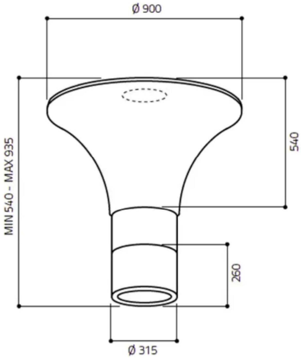
| Dimensions (Hood Body) | Diameter 900 mm, height adjustable 540-935 mm |
| Exhaust Air Duct Diameter | 315 mm (DN 315) |
| Weight | Approx. 25 kg |
| Power Supply | 220-240 V, 50/60 Hz |
| Total Connected Load | Not specified, typical 300 W |
| Fan Speeds | 4 levels (1-4) |
| Lighting | LED, centrally located |
| Control | Radio remote control |
| Height Adjustment | Motorized, 9 positions (1.5 cm per step) |
| Filter Type | Metal grease filter with bayonet fitting |
| Filter Cleaning Interval | Every 2 weeks |
| Filter Cleaning Method | Dishwasher (max 55°C) or hot soapy water |
| Materials | Food-safe plastic, stainless steel, glass |
| Safety Features | Automatic shut-off? Not specified; must not operate without filter |
| Energy Efficiency Class | Not specified |
| Noise Level | Not specified |
| Accessories Included | Remote control, mounting kit, connecting piece DN 150 (adapter) |
Frequently Asked Questions - Wizard ELICA
User questions about Wizard ELICA
0 question about this device. Answer the ones you know or ask your own.
Ask a new question about this device
Download the instructions for your Range hood in PDF format for free! Find your manual Wizard - ELICA and take your electronic device back in hand. On this page are published all the documents necessary for the use of your device. Wizard by ELICA.
USER MANUAL Wizard ELICA
natural_image
Two white funnel-shaped objects with transparent surfaces, one larger and one smaller, labeled 'Wizard' in the corner (no other text or symbols)de
Installation
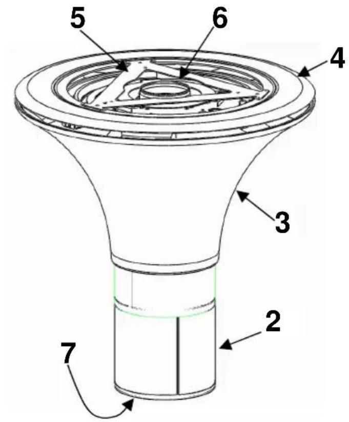
Abb. a
natural_image
Simple line drawing of a cylindrical object with a labeled arrow pointing to its side (no text or symbols present)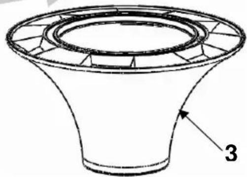
natural_image
Technical line drawing of a conical mechanical component with radial grooves and a labeled part (3), no text or symbols present.Abb. b
Installation
natural_image
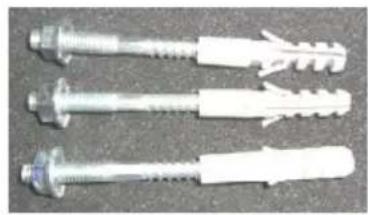
Three plastic mechanical fasteners with threaded end caps, shown against a plain background (no text or symbols visible)3 x M8x80
Abb. c
natural_image
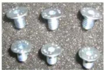
Six metallic screw fasteners arranged on a textured surface (no text or symbols visible)
6 x M5x8
Abb. d
Installation
natural_image
Technical line drawing of a mechanical component with mounting flanges and a central circular housing (no text or symbols)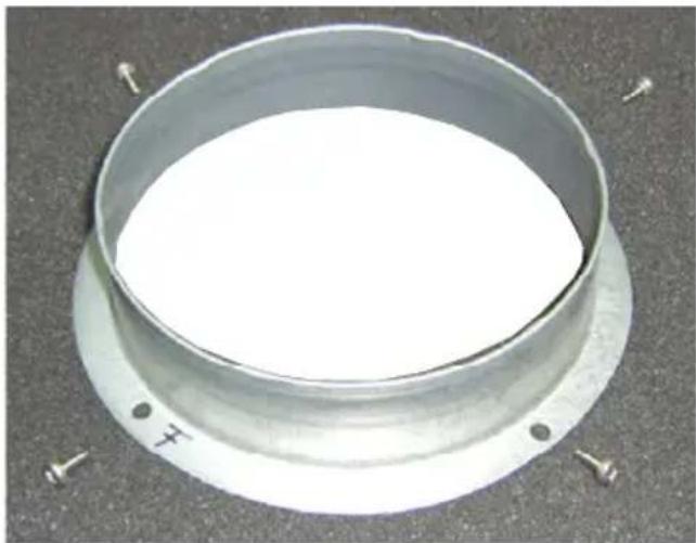
natural_image
Circular metallic component with a central white area, flanked by small screws on a dark textured surface (no text or symbols visible)Abb. e
4 x M4x10
Installation
flowchart
graph TD
    A["Top Component"] --> B["Conveyor"]
    B --> C["Rotating Ring 1"]
    C --> D["Rotating Ring 2"]
    D --> E["Rotating Ring 3"]
    E --> F["Bottom Component"]
    F --> G["Rotating Ring 4"]
    G --> H["Bottom Component"]
    H --> I["Bottom Component"]
    style A fill:#f9f,stroke:#333
    style B fill:#ccf,stroke:#333
    style C fill:#cfc,stroke:#333
    style D fill:#fcc,stroke:#333
    style E fill:#cff,stroke:#333
    style F fill:#ffc,stroke:#333
    style G fill:#cfc,stroke:#333
    style H fill:#fcc,stroke:#333
    style I fill:#ffc,stroke:#333
natural_image
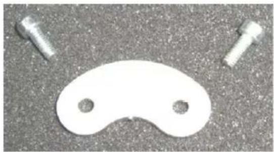
White plastic object with two holes and two bolts on a textured gray surface (no text or symbols)2 x M4x14
natural_image
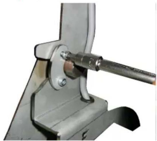
Close-up of a metal clamp or bracket with a screwdriver inserted, no visible text or symbolsAbb. g
Installation
natural_image
Technical diagram of a cylindrical mechanical component with mounting holes and internal structure, showing no text or symbols.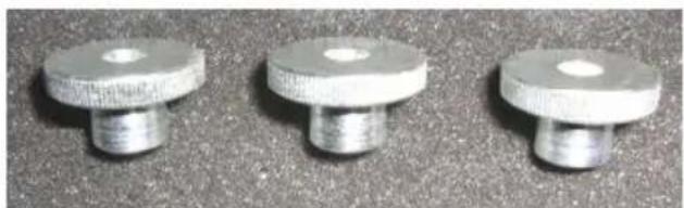
natural_image
Three metallic mechanical flutes on a textured surface (no text or symbols visible)3 x M5
Abb. h
F = Front
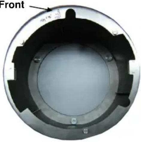
natural_image
Circular mechanical component with black and white sections, labeled 'Front' and a small annotation arrow (no readable text or symbols beyond label)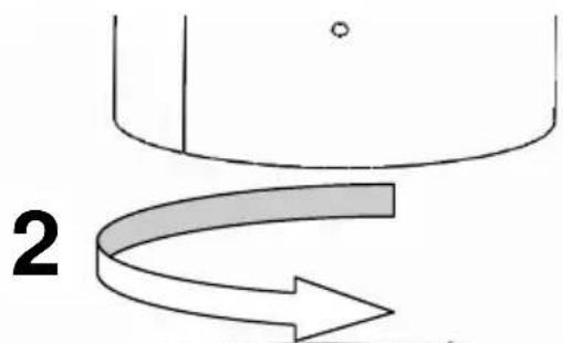
natural_image
Diagram showing a curved arrow labeled '2' pointing downward, with no readable text or symbols.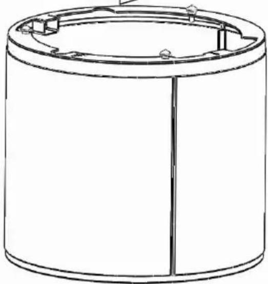
natural_image
Technical line drawing of a cylindrical mechanical component with mounting holes and internal structure (no text or symbols)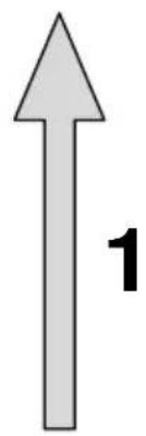
Abb. i
Installation
12
natural_image
Coiled black electrical plug with a terminal connector (no text or symbols visible)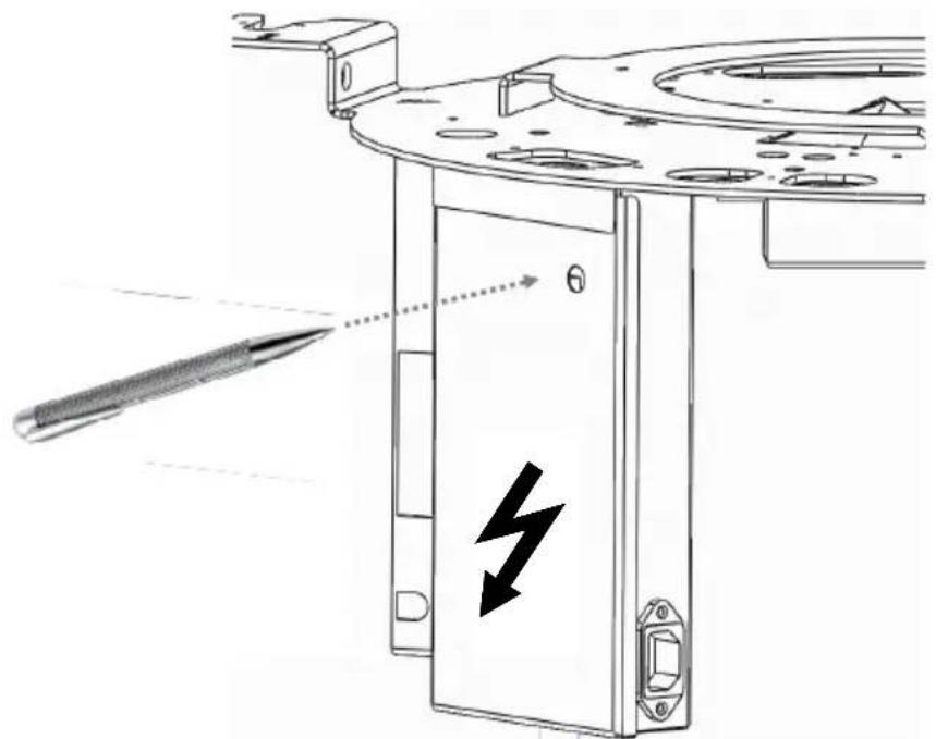
natural_image
Technical line drawing of a mechanical component with a tool and lightning bolt symbol (no text or labels)Abb. k
Installation
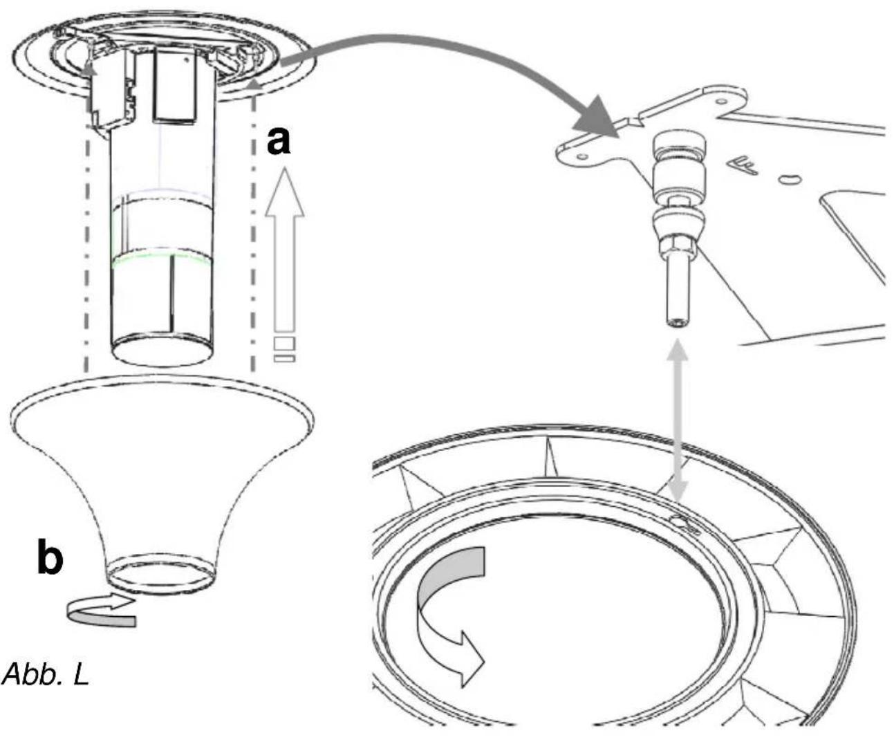
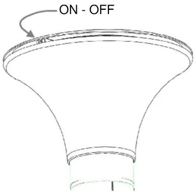
Abb. m
Installation
Sicherheitshinweise
natural_image
Diagram of a cylindrical device with internal components and directional arrows indicating rotation (no text or symbols)natural_image
Diagram of a cylindrical device with internal components and directional arrows indicating motion (no text or symbols)elica to help you enjoy life
Dear customer,
Thank you for choosing a elica extractor hood.
Please carefully read the following information and explanations on the proper use of your new elica hood before using the appliance for the first time. Please also read our operating and installation instructions as well as the cleaning recommendations to ensure that you enjoy many years of service from your appliance.
Safety information
These operating and installation instructions contain important information that must be observed to ensure safe and reliable operation of the extractor hood. Please store them in a safe place for future reference. These operating instructions refer to several versions of the appliance. They may contain descriptions of certain features not found on your model.
The extractor hood must not be used by persons (incl. children) with impaired physical or mental capabilities or persons who lack experience and/or knowledge of how to use it. Children must be supervised to ensure that they do not play with the appliance.
Intended use
The extractor hood may only be used to extract kitchen vapours above the cooking appliances in private households. Any other use will be deemed to be improper. Improper use of the hood may pose a danger to persons and objects. The extractor hood must not be used as a shelf to store objects such as bottles, spice jars or other loose objects.
Installation
The appliance may only be installed and connected by an authorised technician observing all relevant regulations of the electric utility companies and the applicable building regulations. During installation, observe the relevant instructions! Damaged appliances may not be put into operation. Defective parts must be replaced with genuine parts. Repairs should only be carried out by authorised technical staff.
Danger of intoxication!
If the extractor hood is operated in extraction mode at the same time as other room-air-dependent fire appliances (e.g. wood, gas, oil or coal-fired appliances) in the same room, lethal combustion gases may be directed back into the room due to the resulting negative pressure. For this reason, you must ensure a sufficient air supply at all times! The negative pressure in the room must not exceed 4 Pa (0.04mbar).
Fire hazard!
The extractor hood must never be operated without the grease filter and must always be used under supervision. Filters that are saturated with grease can pose a fire hazard! Keep the extractor hood under constant supervision when deep-frying! Remember to clean out the filters regularly. Flam-béing under the extractor hood is not allowed! Gas appliances may only be used under the extractor hood with saucepans placed over them! If you are using more than three gas rings at the same time, operate the extractor hood at power level "2" or higher. This prevents the build-up of heat in the appliance.
Preparing for use
The extractor hood model complies with the relevant safety regulations for kitchen appliances in private households. The requirements regarding the installation location are described in the user documentation supplied with the appliance. If you have any doubts as to whether your intended installation location meets the requirements, please contact our service department. Damaged appliances may not be put into operation. Defective parts must be replaced with genuine spare parts or parts specified by elica. Repairs should only be carried out by authorised technical staff.
Activated carbon filter
For activated carbon filters fitted in GUTMANN extractor hoods (C Version), please read the separate operating instructions provided!
Transport, unpacking, installation
Condensation may occur if the appliance is brought into the installation site
from a cold environment. Please wait until the appliance has adjusted to the temperature and is completely dry before operating it. The acclimatization period depends on the temperature difference and the type and design of the appliance. However, it should be at least 12 hours.
Connecting the power supply
Check that the rated voltage indicated on the appliance matches the mains voltage in your area. Connection to the incorrect voltage will damage or destroy the appliance.
Before switching on the appliance, check that all cables and lines are properly fitted and undamaged. Make sure in particular that there are no kinks in the cables, that they are not pulled too tightly around corners and that no objects are resting on them. Also make sure that all plug connections are securely inserted. Faulty shielding or wiring poses a health hazard (electric shock) and can destroy other appliances. Appliances with mains plugs are fitted with a safety-tested mains cable for the respective country of use and may only be connected to a correctly earthed safety socket. Otherwise, there is a risk of electric shock. Make sure that the socket on the appliance or the domestic safety socket is easily accessible so that the mains cable can be unplugged from the socket in an emergency or during servicing and maintenance work.
Danger of electric shock!
Do not clean the hood with a steam cleaner or water pressure cleaner. The hood must be disconnected from the power supply prior to cleaning
Safety information
Installation, connection, commissioning and repair work may only be carried out by authorised technicians. This technician will be able to determine suitable methods for securing the extractor hood and providing the necessary exhaust air ducting. The choice of attachment must take account of the weight of the extractor hood and the load exerted on the supporting surface. Note the extraction values of the dowels supplied. Depending on the supporting surface, these have the following values: Dowel ∅10 mm: concrete B25 9.4 kN brick Z20 5.2 KN solid calcium silicate KSV20 4.8 KN. In the case of unstable supporting surfaces, a construction specialist such as a structural engineer or architect must be consulted to ensure the extractor hood is safely installed.
Danger of injury!
The hood body may contain sharp edges resulting from the manufacturing process. For this reason, safety gloves must be worn when installing it.
Danger of electric shock
The mains voltage must correspond to the details indicated on the type plate. This plate is located inside the hood near the filters. Only connect the extractor hood to a properly installed safety socket. This socket must be easily accessible after the installation so that the extractor hood can be disconnected from the power supply if necessary. If a fixed connection is used (e.g. if a suitable wall socket is not available), the extractor hood may only be connected by a qualified electrician. For fixed connections, the extractor hood must be connected to a single power circuit fitted with an isolating device. Isolating devices include switches with a contact gap of at least 3 mm and all-pole
Installation instructions
switches, e.g. circuit breakers and contactors. Before working on the electrical connection of the extractor hood commences, the mains circuit/circuits must be switched off. Before drilling the mounting holes, make sure that no electrical cables can be damaged during drilling. The electrical connection must be prepared in such a way as to allow the easy connection of the extractor hood. Local regulations must be observed.
Exhaust air ducting (for extraction mode) Exhaust kitchen air must not be ducted into a chimney flue that is also used for the exhaust air from devices using fuels (e.g. gas). Official regulations regarding ducting of exhaust air must be observed. The exhaust air path must be prepared in such as way as to allow the easy connection of the extractor hood. The exhaust air hose must not have any kinks. If the extractor hood is operated in extraction mode at the same time as other room-air-dependent fire appliances (e.g. wood, gas, oil or coal-fired appliances) in the same room, lethal combustion gases may be directed back into the room due to the resulting negative pressure. The operator must therefore provide a sufficient air supply at all times. The negative pressure in the room must not exceed 4 Pa (0.04mbar).
Solid fuel appliances
The installation of the extractor hood above solid fuel appliances, which can pose a fire hazard, (e.g. flying sparks) is only permissible if the solid fuel appliance is equipped with a sealed, non-removable cover.
We reserve the right to make technical changes.
Installation instructions
en
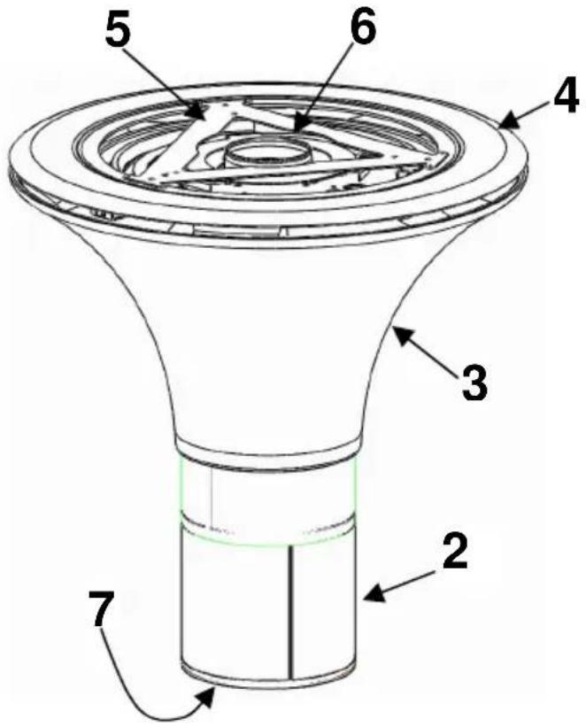
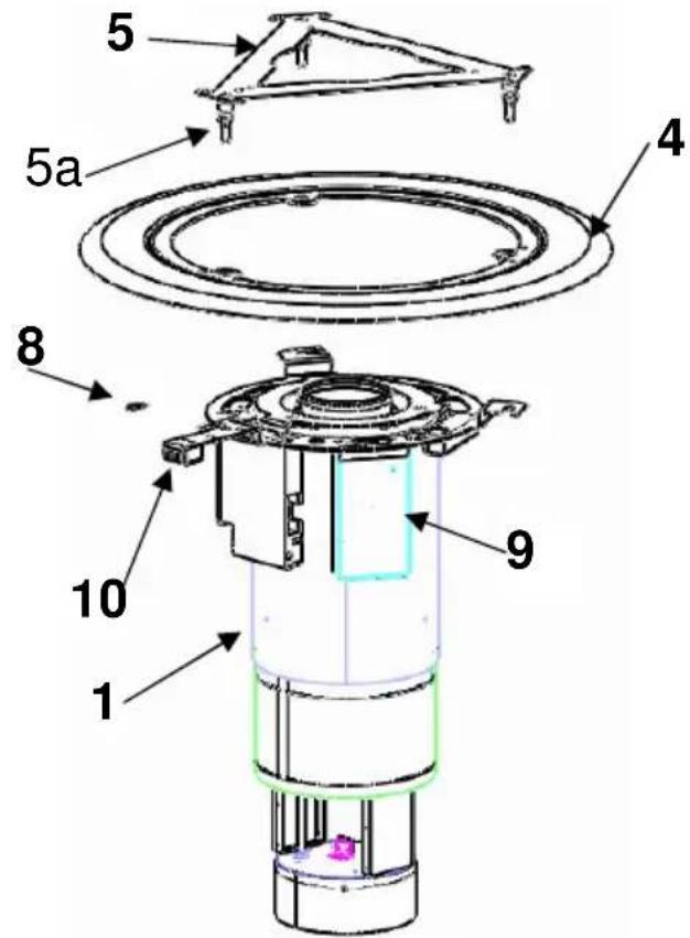

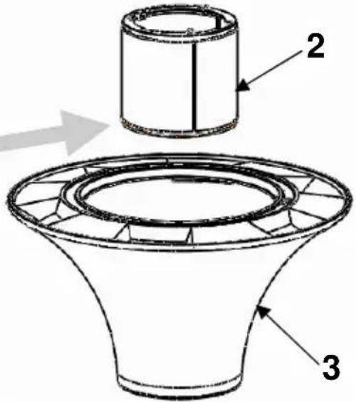
Abb. b
1: Hood body with internal blower motor + drive motor
2: Metal filter with bayonet fitting
3: Plastic carcass
4: Decorative ceiling panel
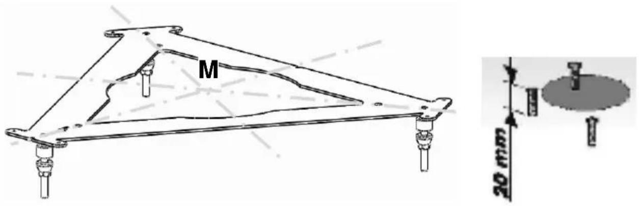
5: Ceiling flange
5a. Snap-on bolts
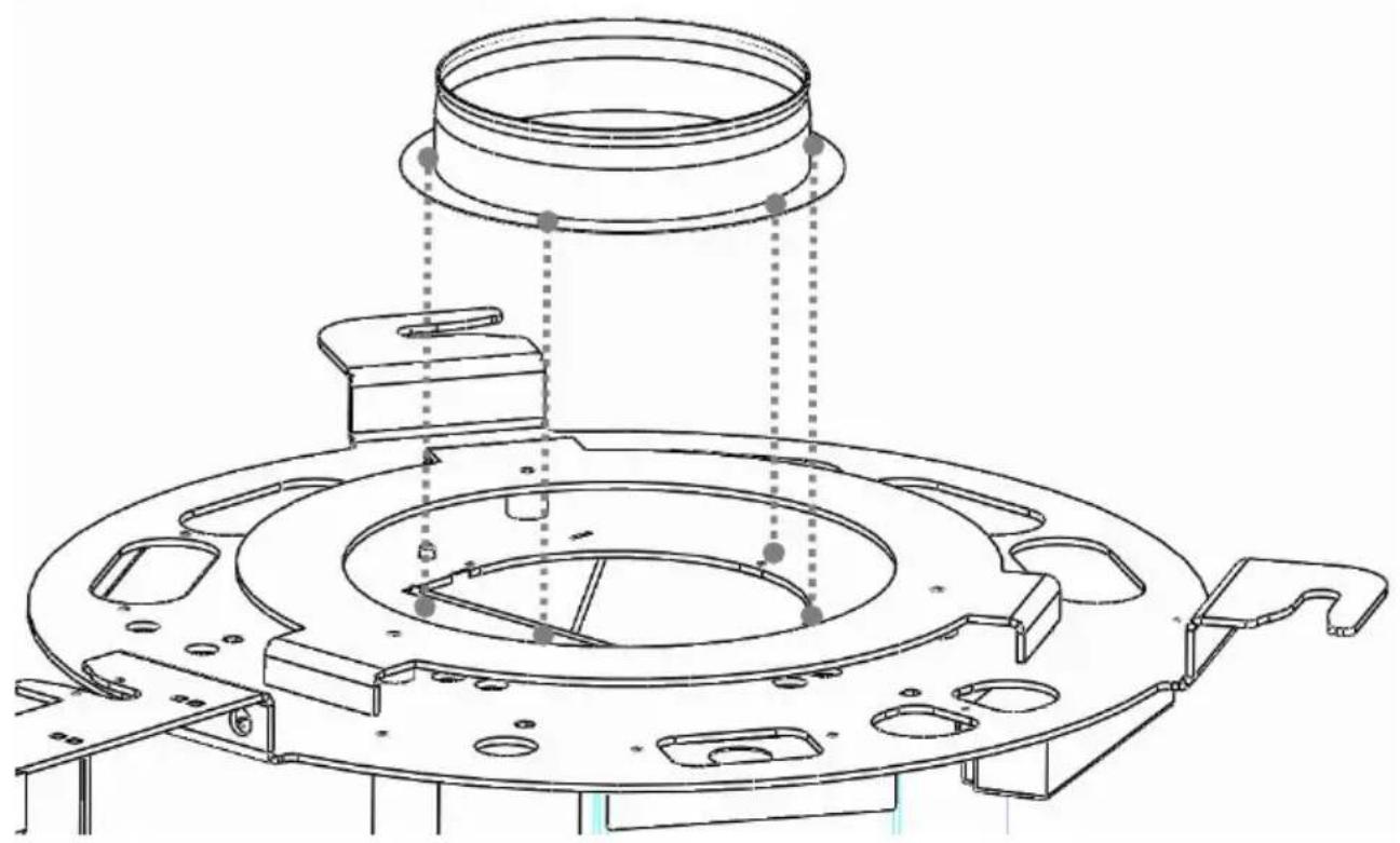
6: Connecting piece DN 150
7: LED lighting
8: Anti-twist mechanism
9: Control unit
10: Main switch
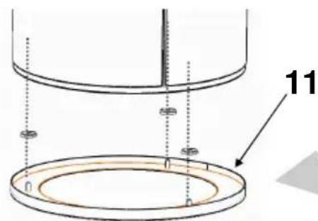
11: Glass
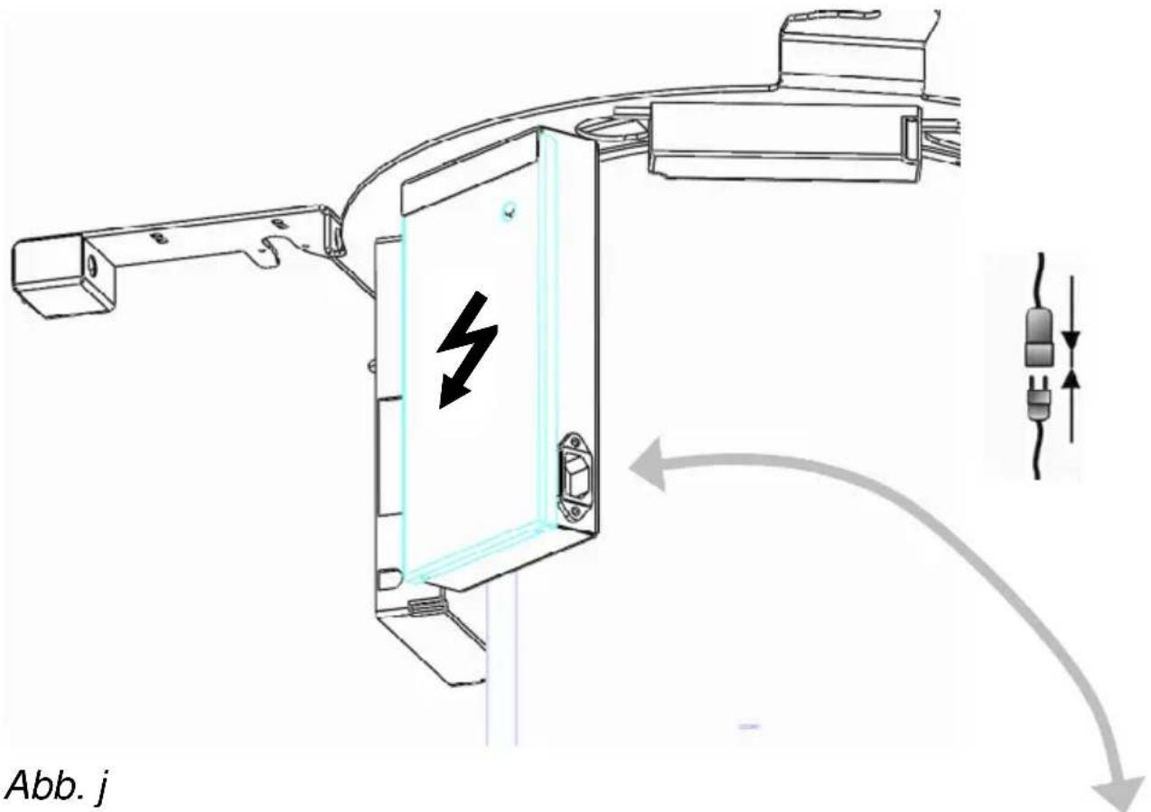
12: Electric connecting cable, loose
13: Radio remote control
Installation instructions
General: before the extractor hood leaves our works it undergoes an extensive functional test. For improved technical understanding of the relation of the functional components, the extractor hood is supplied loose in the following modules for logistical reasons: hood body (1), decorative ceiling panel (4), plastic carcass (3) and remote control (11). These modules should be installed according to the following instructions. Two qualified people are needed for the installation.
Prepare suitable on-site exhaust air facilities in the ceiling. Use a plumb line to determine the central point (M) from the middle of the hob = middle of the extractor hood on the ceiling (Fig. c.). Now transfer the central point onto the ceiling flange (5) and transfer the fastening points onto the ceiling. Drill the fastening holes, insert dowels and screw in the hanger bolts so that approx. 20 mm of thread still protrudes.
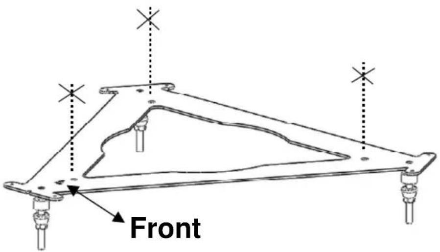
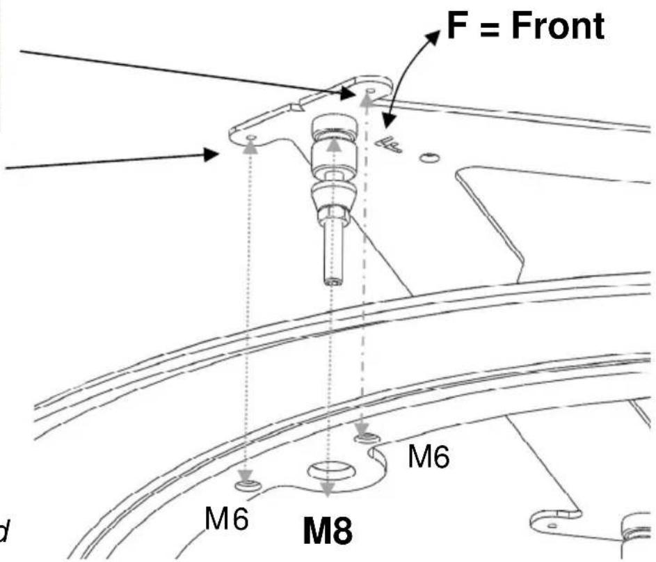
Now screw the ceiling flange (5) to the ceiling ensuring that the F = front side is at the front (Fig. d). When tightening the screws ensure that the ceiling flange is horizontal. Check this with a spirit level if necessary.
→ Screw the decorative ceiling panel (4) (plastic) to the ceiling flange (Fig. d).
→ Fasten the connecting piece (6) to the hood body (1) using the screws supplied (Fig. e).
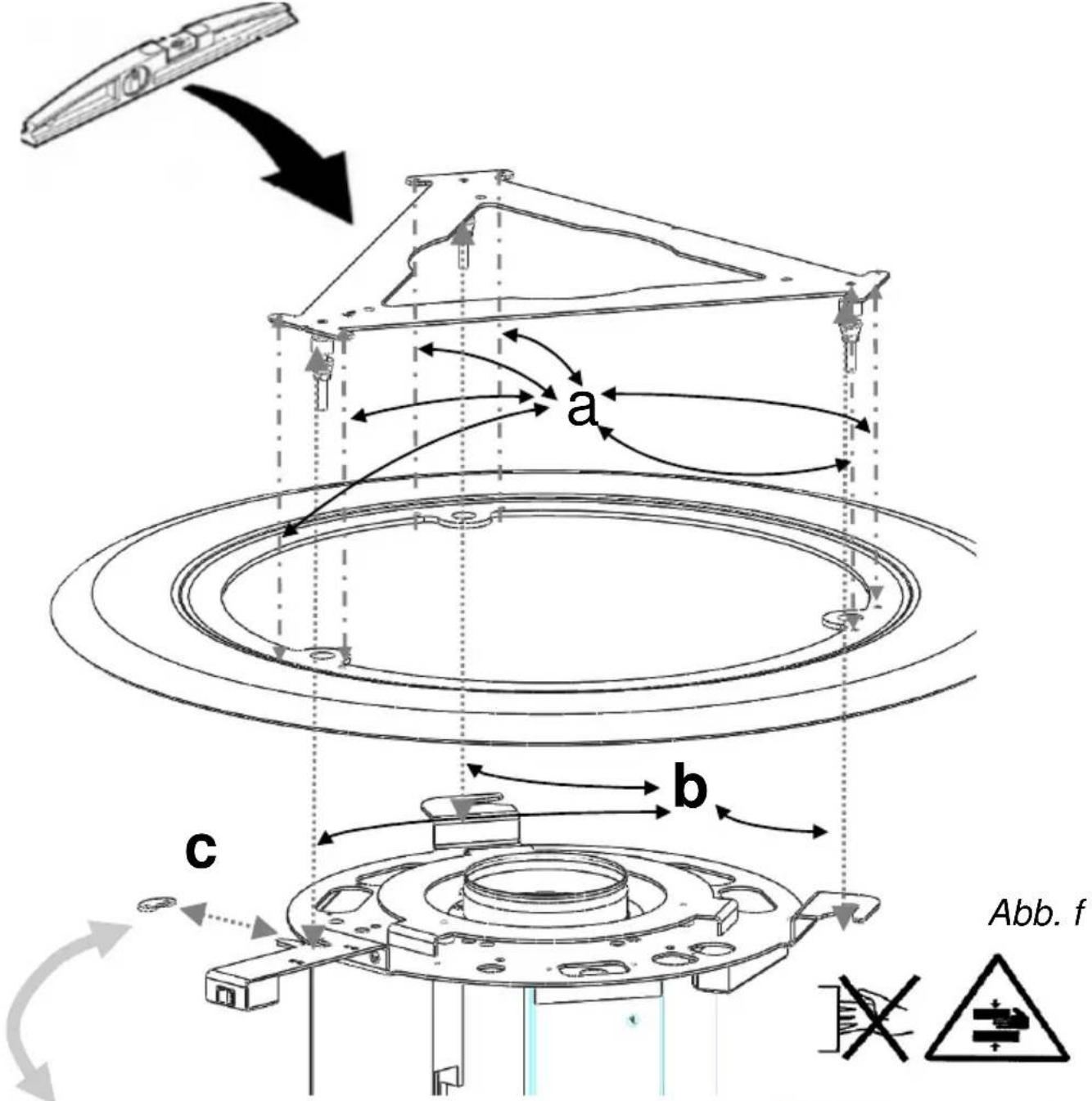
→ Lift up the hood body (1) and insert it into the snap-on bolts (5a) and close the bayonet fitting (Fig. f). Screw on the anti-twist mechanism (8) (Fig. g). (Sequence: a-b-c)
→ Fasten the glass to the metal filter using the three knurled screws (Fig. h). Now insert the metal filter into the hood body and close the bayonet fitting (Fig. i) ensuring that F = front side!
→ Insert the electric connecting cable (12) into the control box and guide it upwards (Fig. j).
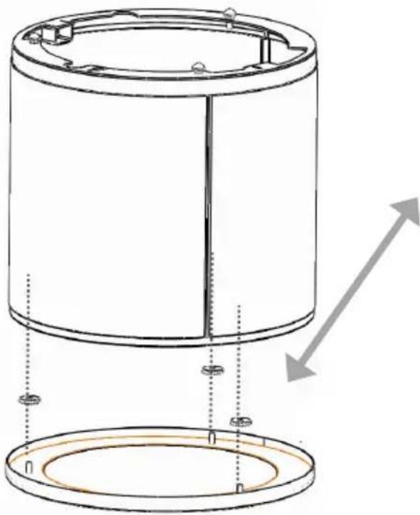
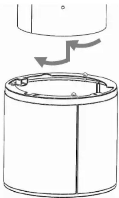
→ Pull the plastic carcass (3) from the hood body (1) upwards over the hood body (a) and twist it until the snap-on bolts lock in place (bayonet fitting) (Fig. L).
Installation instructions
en
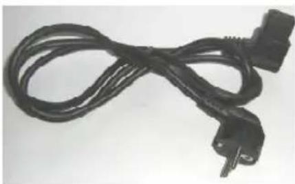
→ Now actuate the switch so that the hood is ready for operation (Fig. m).
The height of the hood can be adjusted to suit the customer if necessary. (Fig. K). Nine different heights can be selected (a=1.5 cm). Press once = 1.5 cm change in height.
Operating Instructions
General method of operation
The innovative height-adjustable Wizard hood offers you an extravagant design. Extraction takes place through a round metal filter that is positioned centrally above the hob. The hood body moves upwards once it is switched off. The hood body itself appears very slim and unobtrusive thanks to its sophisticated design. The LED lighting is positioned centrally in the middle of the metal filter. The metal filter can be easily replaced without any tools (bayonet fittings). A motor raises and lowers the hood body. The extraction capacity is controlled via the control panel that is a radio remote control. The Wizard hood is made of food-safe plastic in combination with stainless steel and glass components.
Product description
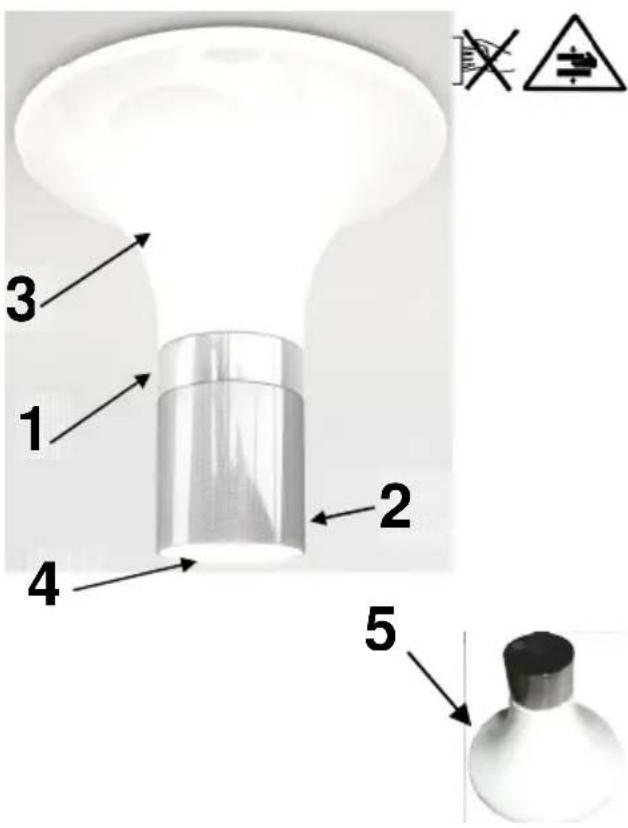
1 Hood body (Hood body lowered)
2 Metal filter
3 Plastic carcass
4 LED lighting
5 Remote control
Operating instructions
The functions of the hood model and the fan power of the blower motor are controlled by radio remote control that works as follows:
Operation via radio remote control
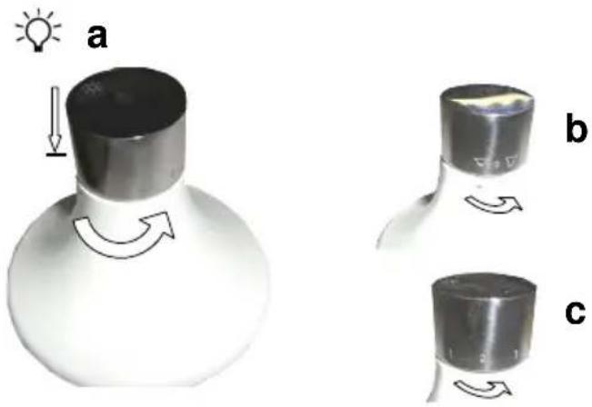
Raising and lowering the hood b
Turn knob b once to the right to lower the hood = hood extends downwards (see symbol).
Fan power C
Turn the button to the right to adjust the fan power from level 1 - 4 (see symbols 1-4).
Lighting A
Press the lighting symbol to switch on the lighting. Press it again = lighting off.
Cleaning and care
Cleaning the surfaces
Danger due to electric shock! Disconnect the extractor hood from the power supply by pulling the plug out of the socket or by switching off the fuse. When cleaning, make sure that no water penetrates the device.
Regular cleaning of the surface saves laborious removal of stubborn contamination. Only use conventional detergents or universal cleaning agents suitable for cleaning stainless steel/aluminium. Never use abrasive cleaning agents or steel wool. After cleaning the hood, treat the stainless steel surfaces with a stainless steel care product.
Painted surfaces should only be cleaned using a mild detergent solution and a very soft cloth. Only use a soft damp cloth to clean the operating panel.
On hoods fitted with a panel below the filter (edge extraction), grease deposits occur at the edge of the panel. These deposits occur for physical reasons and are not due to a malfunction of the hood. Please clean the panel underneath the filter regularly to prevent the formation of stubborn residues.
Cleaning and care instructions
When cleaning the grease filters, also remove any grease deposits from the accessible housing components. This will prevent a fire hazard and maintain an optimum range of functions. Use hot soapy water or a mild window cleaning agent to clean the hood. Do not scratch off baked-on deposits. Soften them using a damp cloth. Do not use abrasive agents or scouring pads.
Note: Do not use alcohol (spirits) on plastic surfaces, as dull spots may result.
Caution: Ventilate the kitchen sufficiently, no open flame.
Only clean the operating panel with a soft damp cloth (mild detergent solution). Do not use stainless steel cleaners for the sliding switch/pressure switch.
Stainless steel surfaces:
Use a mild and non-abrasive stainless steel cleaning agent. Do not clean stainless steel surfaces with abrasive scouring pads or with cleaning agents containing sand, soda, acid or chloride! Clean in direction of polish only.
We recommend our stainless steel cleaner no. 461731. See the enclosed service booklet for the order address.
Aluminium, varnished and plastic surfaces:
Use a soft microfibre cloth. Do not use dry cloths. Use a mild window-cleaning agent. Do not use aggressive cleaning agents or agents containing acid or lye! Do not use scouring agents.
Metal filter changing
Removing filters
Fire hazard! The performance of the extractor hood is reduced by grease residues and the fire hazard increases. The metal filter must be cleaned regularly to prevent a fire hazard. The grease filters must be cleaned at least once a fortnight. To do this, turn the metal filter to the left from the operating side until the bayonet fitting opens. Pull the filter downwards to remove it. The filter is fitted in the reverse order. When fitting the filter, ensure that F = front side!
natural_image
Diagram of a cylindrical device with internal components and directional arrows indicating rotation (no text or symbols)Operating Instructions
Exchange and cleaning of the filter
Fire risk! The performance of the extractor hood is affected by containing fat remains and therefore the fire risk increases. To prevent a fire risk please clean the metal filter regularly. The metal grease filter must be cleaned every 2 weeks at last.
At first press therefore the stainless steel pane with both hands upwards and then slowly down. The underlying metal grease filter is held by a magnet and can be simply flapped down.
The metal grease filter is to be cleaned at best in a dishwasher or in hot soapy water. Aggressive cleaners should not be used. The guarantee can't be applied if a discolouring on the filter is a result of using an aggressive dishwashing liquid.
Please avoid temperatures over 55 degrees. Attention: do not use 3-phase-cleaners or clean the filter in a commercial dishwasher. The use of aggressive cleaners like fuel, acetone, trichlorethylene destroys the filter!
Reinstate the metal filter after the cleaning and close the stainless steel pane with both hands.
Lighting
Standard model with LED lighting! Changing of the LED lighting only possible by the service department!
Faults
Please contact our service department immediately, if:
- If the extractor hood creates unusual noises and you are unable to detect any faults after checking the extraction air line
- If you discover, for example, by hearing strange noises, that the motor is faulty or defective
- the switches are not working properly.
Please remember to indicate your extractor hood model and the corresponding serial number. This information can be found on the type plate. This plate is located inside the hood near the filters.
Disposal
Packaging
The packaging for the extractor hood is recyclable. Cardboard and polyethylene film (PE) are used as packaging materials. These materials must be disposed of in an environmentally compatible manner in accordance with local regulations.
Extractor hood
Your local authority will also be happy to advise you on the environmentally sound disposal of old household appliances.
Environmental informa-
tion

All models manufactured by elica are identified in accordance with European Directive 2002/96/EC on waste electrical and electronic equipment (WEEE). This directive specifies the framework for the EU-wide return and disposal of used appliances. Please ask your dealer for information about current disposal methods.
We reserve the right to make technical changes.
elica
aria nuova
Via Dante n°288
60044 Fabriano (AN) Italia
C.F. Reg. Imp. AN 00096570429
Cap. Soc. Euro 12.664.560 i.v.