
DS-9116HFI-XT - Security Camera Hikvision - Free user manual and instructions
Find the device manual for free DS-9116HFI-XT Hikvision in PDF.


User questions about DS-9116HFI-XT Hikvision
0 question about this device. Answer the ones you know or ask your own.
Ask a new question about this device
Download the instructions for your Security Camera in PDF format for free! Find your manual DS-9116HFI-XT - Hikvision and take your electronic device back in hand. On this page are published all the documents necessary for the use of your device. DS-9116HFI-XT by Hikvision.
USER MANUAL DS-9116HFI-XT Hikvision
natural_image
Pure architectural or mechanical diagram with no visible text, numbers, or symbols
Bellman & Symfon®
DESIGN FOR EARS

text_image
Diagram showing hand positioning of a device with labeled components and directional arrows, including a 'Max 3cm' indicator.text_image
Diagram showing hand holding a door panel with lock and handle, labeled with number 1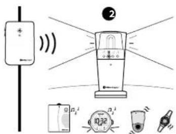
text_image
Diagram showing a device with signal waves and labeled components including a timer, alarm unit, and water drop.Programmierung
77 Introduction
79 Installation
82 Testing
83 Programming
84 Using the External microphone
85 Using electromagnetic detection
91 Trouble shooting
93 Technical information

Introduction
Function
The door transmitter is part of the Visit alerting system that helps people with hearing loss to notice signals in their home. It detects both doorbells and intercoms.
Activation
The door transmitter can be activated by either:
■ The internal microphone (default)
■ The built-in electromagnetic detector
■ The External microphone accessory, art. no. BE9199 (2.5 m) / BE9200 (0.75 m)
■ The existing doorbell connected to the Ext trig
Using the built-in microphone
The door transmitter is programmed from the start to recognize the majority of doorbells and intercoms. If the doorbell signal varies significantly in strength or tone, you can program it to recognize the sound (see Programming on page 83).
Overview
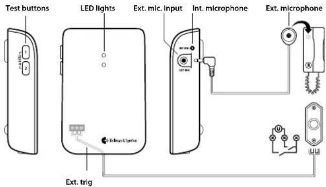
text_image
Test buttons LED lights Ext. mic. Input Int. microphone Ext. microphone Ext. trigBasic installation - single sound source
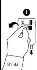
1 Remove the battery pull tag to start the door transmitter. Clean the wall with the wet wipe and remove the protective film from the velcro.
2 Mount the door transmitter to the left of the doorbell's sound source as close as possible. You can also use the supplied screw and plug.
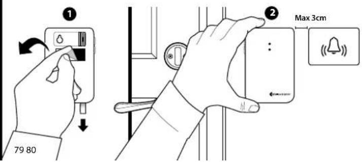
text_image
① 79 80 ② Max 3cmInstallation – intercom and electronic doorbell
1 Connect the external microphone to the door transmitter. Remove the protective film from the microphone and attach it to the intercom's speaker.
2 Remove the battery pull tag to start the door transmitter. Clean the wall with the wet wipe and remove the protective film from the velcro.
3 Mount the door transmitter to the left of the doorbell's sound source as close as possible. You can also use the supplied screw and plug.
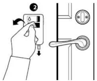
text_image
Diagram showing a hand holding a switch with directional arrows and a close-up of the door handle mechanism.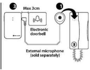
text_image
3 Max 3cm Electronic doorbell External microphone (sold separately) 1Installation - intercom and mechanical doorbell
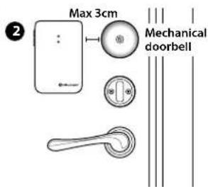
If you have an intercom and a mechanical doorbell, you may need two door transmitters, i.e. one for each sound source. Proceed as follows:
1 Pull the battery pull tab to start each door transmitter. Clean the wall surface with the wet wipe and remove the protective film from the velcro.
2 Mount a door transmitter to the left of the doorbell and another to the left of the intercom's speaker, as close to the sound sources as possible.
text_image
Max 3cm Mechanical doorbell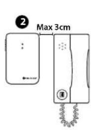
text_image
2 Max 3cmTesting
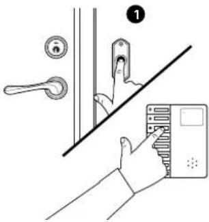
1 Ring the doorbell or intercom.
2 The Visit receiver lights up a door symbol and indicates with sound, lights or vibrations (depending on the receiver). If it doesn't react, read the section Programming.
text_image
Diagram showing a hand installing a door panel with a lock and handle, labeled with number 1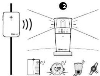
text_image
Diagram showing a smart air conditioner with labeled components including speaker, alarm, and control unitProgramming
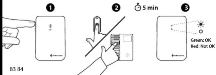
You can teach the door transmitter to recognize the sound of your doorbell.
1 Press and hold button 1 until the LED blinks. Release it to start the recording.
2 Ring the doorbell 5 times (pause between each press). The recording lasts for 5 min and ends automatically. Press button 1 to stop it manually.
3 When it's finished, the LED stops blinking. If the LED is red, see Trouble shooting. Record the intercom with button 2 by repeating steps 1-2 above.
text_image
1 83 84 2 5 min 3 Green: OK Red: Not OKUsing the External microphone
Connect the External microphone accessory to the microphone socket (see Overview). The External microphone is used in the following scenarios:
1 When the sound source is located too far away from the internal microphone
2 When you need individual notifications from eg. the doorbell and intercom The default signal pattern on the receiver is as follows:
| Triggered microphone | Light Vibration Sound | |
| Internal microphone | Green light Slow pattern 1 x ding dong, Lo | |
| External microphone | Blinking in green Slow pattern 2 x ding dong, Hi |
You can easily customize the receiver's signal pattern by moving the signal switches on the door transmitter according to the tables on page 87-90.
Please note: Do not place the External microphone too close to the door transmitter. This might cause interference.
Using electromagnetic detection
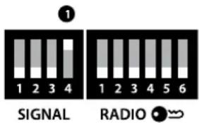
The door transmitter can be set to detect electromagnetic fields emitted by electromechanical doorbells. You only need to use this function if the programming of the door transmitter has failed. Here is how it's done:
■ Activating electromagnetic detection Move the 4th signal-switch 1 to the Up=On position.
■ Deactivating electromagnetic detection Move the 4th signal-switch to the Down=Off position.
text_image
1 1 2 3 4 SIGNAL 1 2 3 4 5 6 RADIOClear the recorded sounds
To clear all recorded sounds, press and hold button 1 and 2 simultaneously for 5s.
Please note: This will clear the sounds that has been recorded during programming. All radio key settings and transmitted signal settings will be kept intact.
Customizing the signal
The door transmitter controls the signal pattern on the receiver. To customize the signal pattern, move the signal switches A according to the tables on the following spreads.
Switch no. 4 is for electromagnetic detection.
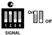
Changing the radio key
If you install multiple systems, you can set a unique radio key for each system to avoid radio interference. Move any radio key switch B to the up=on position to change the radio key.
Please note
All Visit products within the same system must be set to the same radio key in order to operate as a group.
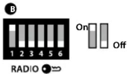
Signal output for 868 MHz and 315 MHz
| Dip switch Output | Test button 1 and 2 Learned signal 1 | External microphone Learned signal 2 | External trigger | |
 | Light Green light Blinking in green 3 x green blinks | |||
| Vibration Slow pattern Slow pattern Slow pattern | ||||
| Sound 1 x ding dong, Lo 2 x ding dong, Hi 1 x ding dong, Hi | ||||
 | Light 2 x green blinks 3 x green blinks Blinking in green | |||
| Vibration Slow pattern Slow pattern Slow pattern | ||||
| Sound 2 x ding dong, Lo 1 x ding dong, Hi 2 x ding dong, Hi | ||||
 | Light 3 x green blinks 2 x green blinks 3 x orange blinks | |||
| Vibration Slow pattern Slow pattern Rapid pattern | ||||
| Sound 1 x ding dong, Hi 2 x ding dong, Lo Baby melody | ||||
 | Light Blinking in green Green light Blinking in orange | |||
| Vibration Slow pattern Slow pattern Rapid pattern | ||||
| Sound 2 x ding dong, Hi 1 x ding dong, Lo Baby melody | ||||
| Dlp switch Output | Test button 1 and 2 Learned signal 1 | External microphone Learned signal 2 | External trigger | |
| Light Green light | 3 x green blinks | 2 x green blinks | ||
| Vibration Slow pattern | Slow pattern | Slow pattern | ||
| Sound 1 x ding dong, Lo 1 x ding dong, Hi 2 x ding dong, Lo | ||||
| Light Green light | Blinking in green Blinking in yellow | |||
| Vibration Slow pattern | Slow pattern | Fast pattern | ||
| Sound 1 x ding dong, Lo 2 x ding dong, Hi 2 x ring ring, Hi | ||||
| Light | 3 x green blinks | Green light | VMA | |
| Vibration Slow pattern | Slow pattern | 50% on/off | ||
| Sound | 1 x ding dong, Hi | 1 x ding dong, Lo | VMA | |
| Light | Blinking in green | 2 x green blinks | Fire alert | |
| Vibration Slow pattern | Slow pattern | 50% on/off | ||
| Sound 2 x ding dong, Hi | 2 x ding dong, Lo | Smoke alert | ||
Signal output for 433 MHz
| Dlp switch Output | Test button 1 and 2 Learned signal 1 | External microphone Learned signal 2 | External trigger | |
 | Light Green light Green light Green | light | ||
| Vibration Slow pattern Fast pattern | Slow pattern | |||
| Sound 1 x ding dong, Lo 1 x ring, Hi | 1 x ding dong, Lo | |||
 | Light Green light Green light Green | light | ||
| Vibration Fast pattern Slow pattern | Fast pattern | |||
| Sound 1 x ring, Hi 1 x ding dong, Lo | 1 x ring, Hi | |||
 | Light Green light Green light Orange | light | ||
| Vibration Slow pattern Fast pattern | Slow pattern | |||
| Sound 1 x ding dong, Lo 1 x ring, Hi | Baby melody | |||
 | Light Green light Green light Orange | light | ||
| Vibration Fast pattern Slow pattern | Slow pattern | |||
| Sound 1 x ring, Hi 1 x ding dong, Lo | Baby melody | |||
| Dlp switch Output | Test button 1 and 2 Learned signal 1 | External microphone Learned signal 2 | External trigger | |
 | Light Green light Green light | Yellow light | ||
| Vibration Slow pattern | Fast pattern Fast pattern | |||
| Sound 1 x ding dong, Lo 1 x ring, Hi | 1 x ring, Lo | |||
 | Light Orange light Green light Orange light | |||
| Vibration Slow pattern Slow pattern Slow pattern | ||||
| Sound Baby melody 1 x ding dong, Lo Baby melody | ||||
 | Light Green light Green light | VMA | ||
| Vibration Slow pattern Fast pattern Continuous pattern | ||||
| Sound 1 x ding dong, Lo 1 x ring, Hi | VMA | |||
 | Light Green light Green light | Fire alert | ||
| Vibration Slow pattern Fast pattern Continuous pattern | ||||
| Sound 1 x ding dong, Lo 1 x ring, Hi Fire alert | ||||
Trouble shooting
| If Try this | |
| Two orange lights appear every minute | · Change the batteries. Only use 1.5 V AA (LR6) lithium or alkaline batteries. |
| An orange light appears every second | · There are other competing sound sources around the door transmitter. Switch them off or turn them down.· Disconnect the External microphone to make sure it is not faulty. |
| A green light appears when you press the door-bell – but the receiver is not activated | · Check the door transmitter's and the receiver's batteries and plugs.· Move the receiver closer to the door transmitter.· Check that the door transmitter and the receiver are set to the same radio key. For more information, see Changing the radio key. |
| If Try this | |
| No green light appears on the door transmitter when you ring the doorbell | Ring the doorbell while moving the door transmitter closer and further away from the sound source. The ideal distance between the door transmitter microphone and the sound source is < 3 cm.Program the door transmitter to recognize the doorbell's sound. See Programming.If the signal varies a lot in strength/tone, change to magnetic detection, see Using electromagnetic detection.If the door transmitter is still not activated, press and hold button 1 and 2 simultaneously for 5 seconds to clear the recorded sounds and repeat the steps above. |
| The receiver is activated for no reason | There is probably another Visit system installed nearby that triggers your system. Change the radio key on all units, see Changing the radio key. |
Technical information
Power supply Battery power: 2 x 1.5 V AA (LR6) lithium or alkaline batteries.
Power consumption Active < 70 mA, Idle position < 15 μA
Operating time Alkaline \~ 5 years, Lithium \~ 10 years
Activation Via test buttons, internal microphone, electromagnetic detection, External microphone input, ext trig input
Radio frequency 315 MHz, 433.92 MHz or 868.3 MHz depending on region
Coverage 50 - 250 m depending on radio frequency. Coverage is reduced by walls, large objects and other radio transmitters.
Number of radio keys 64 as standard. Up to 256 with optional software.
Accessories BE9199 External microphone 2.5 m, BE9200 External microphone 0.75 m
Additional information
Usage and storage For indoor use only. Temp.: 15°-35° C. Relative humidity: 5% -95%.
Maintenance and cleaning Maintenance free. Clean with a dry cloth. Don't use household cleaners, aerosol sprays, solvents, alcohol, ammonia, or abrasives. Not reusable.
Warranty and service If your door transmitter appears to be damaged or doesn't function properly, follow the advice in this booklet and the online resources. If it still doesn't function properly, contact your retailer for information about obtaining warranty service.
CE Hereby, Bellman & Symfon declares that this Door transmitter is in compliance with the essential requirements and other relevant provisions of directives: RATTE 1988/5/EC, LVD 1973/23/EC, EMC 1989/336/EC, MDD 1993/42/EEC.
Use and disposal of batteries Replace only with the same or equivalent type recommended by the manufacturer. Please dispose of old, defective batteries in an environmentally friendly manner in accordance with the relevant legislation in your country.
FCC compliance statement This device complies with Part 15 of the FCC Rules. Operation is subject to the following two conditions: (1) this device may not cause harmful interference, and (2) this device must accept any interference received, including interference that may cause undesired operation.
Warning: Changes or modifications to this unit not expressly approved by the party responsible for compliance could void the user's authority to operate the equipment.
Note: This equipment has been tested and found to comply with the limits for a Class B digital device, pursuant to Part 15 of the FCC Rules. These limits are designed to provide reasonable protection against harmful interference in a residential installation. This equipment gener-
ates, uses and can radiate radio frequency energy and, if not installed and used in accordance with the instructions, may cause harmful interference to radio communications. However, there is no guarantee that interference will not occur in a particular installation. If this equipment does cause harmful interference to radio or television reception, which can be determined by turning the equipment off and on, the user is encouraged to try to correct the interference by one or more of the following measures:
- Reorient or relocate the receiving
- Increase the separation between the equipment and receiver. - Connect the equipment into an outlet on a circuit different from that to which the receiver is connected.
- Consult the dealer or an expe-
rienced radio/TV technician for help.
For a complete Declaration of Con- formity please contact the Belman & Symfon European office.
Industry Canada statement This device complies with industry Canada Licence-exempt: PSS-210. Operation is subject to the fol- lowing two conditions:
(1) this device may not cause interference, and (2) this device must
European office
accept any interference, including interference that may cause undesired operation of the device.
This Class B digital a peratus complies with the Canadian ICES-003.
text_image
QR code image containing encoded data, no visible human-readable textbellman.com
BE1411_055MAN010