
XPS 12-9Q34 - Laptop DELL - Free user manual and instructions
Find the device manual for free XPS 12-9Q34 DELL in PDF.


| Product Type | Laptop (Convertible) |
| Brand | Dell |
| Model | XPS 12-9Q34 |
| Regulatory Model | P20S |
| Regulatory Type | P20S002 |
| Processor | Intel Core (4th generation or later) |
| Memory | Upgradeable (SO-DIMM slots) |
| Storage | mSATA SSD (upgradeable) |
| Display | 12.5-inch Full HD touchscreen |
| Wireless | Wi-Fi + Bluetooth (M.2 card) |
| Battery Type | Lithium-ion, 8-cell |
| Battery Capacity | Approx. 50 Wh |
| Power Adapter | 45 W or 65 W (depending on configuration) |
| Operating System | Windows 8.1 or later |
| Weight | Approx. 1.5 kg (3.3 lbs) |
| Dimensions | Approx. 320 x 215 x 20 mm |
| Keyboard | Backlit chiclet keyboard |
| Camera | Front-facing HD webcam |
| Ports | USB 3.0, HDMI, audio jack, power connector |
| Repairability | User-serviceable components: battery, SSD, wireless card, fan, etc. |
Frequently Asked Questions - XPS 12-9Q34 DELL
User questions about XPS 12-9Q34 DELL
0 question about this device. Answer the ones you know or ask your own.
Ask a new question about this device
Download the instructions for your Laptop in PDF format for free! Find your manual XPS 12-9Q34 - DELL and take your electronic device back in hand. On this page are published all the documents necessary for the use of your device. XPS 12-9Q34 by DELL.
USER MANUAL XPS 12-9Q34 DELL
Regulatory model: P20S
Regulatory type: P20S002
Notes, Cautions, and Warnings

NOTE: A NOTE indicates important information that helps you make better use of your computer.

CAUTION: A CAUTION indicates potential damage to hardware or loss of data if instructions are not followed.

WARNING: A WARNING indicates a potential for property damage, personal injury, or death.
Contents
Before Working Inside Your Computer ..... 7
Before You Begin 7
Recommended Tools. 7
Safety Instructions....8
After Working Inside Your Computer....9
Removing the Base Cover 10
Procedure 10
Replacing the Base Cover 12
Procedure 12
Removing the Battery 13
Prerequisites. 13
Procedure 13
Replacing the Battery 14
Procedure 14
Postrequisites.... 14
Removing the Wireless Card 15
Prerequisites. 15
Procedure 15
Replacing the Wireless Card 16
Procedure 16
Postrequisites.... 16
Removing the mSATA Card 17
Prerequisites. 17
Procedure 17
Replacing the mSATA Card 18
Procedure 18
Postrequisites.... 18
Removing the Speakers....19
Prerequisites. 19
Procedure 19
Replacing the Speakers 20
Procedure 20
Postrequisites.... 20
Removing the Coin-Cell Battery....21
Prerequisites. 21
Procedure 21
Replacing the Coin-Cell Battery 23
Procedure 23
Postrequisites.... 23
Removing the I/O Board 24
Prerequisites. 24
Procedure 24
Replacing the I/O Board 25
Procedure 25
Postrequisites.... 25
Removing the Fan 26
Prerequisites. 26
Procedure 26
Replacing the Fan. 28
Procedure 28
Postrequisites.... 28
Removing the Heat Sink 29
Prerequisites. 29
Procedure 29
Replacing the Heat Sink 30
Procedure 30
Postrequisites.... 30
Removing the Power-Adapter Port 31
Prerequisites. 31
Procedure 31
Replacing the Power-Adapter Port 32
Procedure 32
Postrequisites.... 32
Removing the System Board 33
Prerequisites. 33
Procedure 33
Replacing the System Board 36
Procedure 36
Postrequisites.... 36
Entering the Service Tag in the BIOS. 36
Removing the Display Assembly 37
Prerequisites. 37
Procedure 37
Replacing the Display Assembly 39
Procedure 39
Postrequisites.... 39
Removing the Display Back-Cover 40
Prerequisites. 40
Procedure 40
Replacing the Display Back-Cover 42
Procedure 42
Postrequisites.... 42
Removing the Camera Module 43
Prerequisites. 43
Procedure 43
Replacing the Camera Module 44
Procedure 44
Postrequisites.... 44
Removing the Windows-Button Board ..... 45
Prerequisites. 45
Procedure 45
Replacing the Windows-Button Board 46
Procedure 46
Postrequisites.... 46
Removing the Display Panel 47
Prerequisites. 47
Procedure 47
Replacing the Display Panel 49
Procedure 49
Postrequisites.... 49
Removing the Keyboard 50
Prerequisites. 50
Procedure 50
Replacing the Keyboard 54
Procedure 54
Postrequisites.... 55
Flashing the BIOS....56
Before You Begin

CAUTION: To avoid data loss, save and close all open files and exit all open programs before turning off your computer.
1 Save and close all open files, exit all open programs, and turn off your computer. Microsoft Windows 8: Point to the lower/upper-right corner of the screen to open the Charms sidebar and click Settings→Power→Shut down.

NOTE: If you use a different operating system, see the documentation of your operating system for shut-down instructions.
2 After the computer shuts down, disconnect it from the electrical outlet.
3 Disconnect all cables — such as power and USB cables — from your computer.
4 Disconnect all peripherals connected to your computer.
Recommended Tools
The procedures in this document require the following tools:
• Phillips screwdriver
- Torx #5 (T5) screwdriver
- Plastic scribe
Safety Instructions
Use the following safety guidelines to protect your computer from potential damage and ensure your personal safety.

WARNING: Before working inside your computer, read the safety information that shipped with your computer. For more safety best practices, see the Regulatory Compliance home page at dell.com/regulatory_compliance.

WARNING: Disconnect all power sources before opening the computer cover or panels. After you finish working inside the computer, replace all covers, panels, and screws before connecting to the power source.

CAUTION: Only a certified service technician is authorized to remove the computer cover and access any of the components inside the computer. See the safety instructions for complete information about safety precautions, working inside your computer, and protecting against electrostatic discharge.

CAUTION: To avoid damaging the computer, make sure that the work surface is flat and clean.

CAUTION: When you disconnect a cable, pull on its connector or on its pull-tab, not on the cable itself. Some cables have connectors with locking tabs or thumb-screws that you must disengage before disconnecting the cable. When disconnecting cables, keep them evenly aligned to avoid bending any connector pins. When connecting cables, make sure that the ports and connectors are correctly oriented and aligned.

CAUTION: To avoid damaging the components and cards, handle them by their edges and avoid touching pins and contacts.

CAUTION: Before touching anything inside your computer, ground yourself by touching an unpainted metal surface, such as the metal at the back of the computer. While you work, periodically touch an unpainted metal surface to dissipate static electricity, which could harm internal components.

CAUTION: Leaving stray or loose screws inside your computer may severely damage your computer.
1 Replace all screws and make sure that no stray screws remain inside your computer.
2 Connect any cables, peripherals, and other parts you removed before working on your computer.
3 Connect your computer to the electrical outlet.
4 Turn on your computer.

WARNING: Before working inside your computer, read the safety information that shipped with your computer and follow the steps in "Before Working Inside Your Computer" on page 7. After working inside your computer, follow the instructions in "After Working Inside Your Computer" on page 9.
For more safety best practices, see the Regulatory Compliance home page at dell.com/regulatory_compliance.
Procedure
1 Close the display, and turn the computer over.
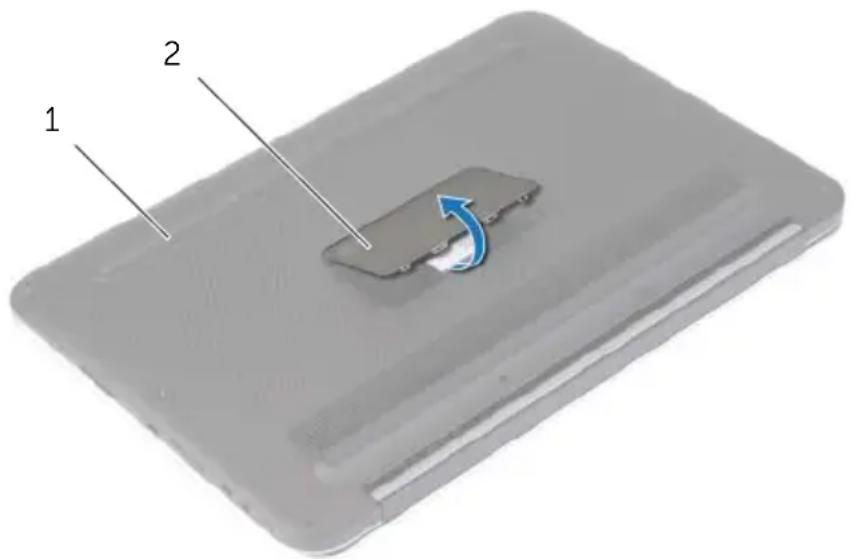
2 Turn the system badge over and place it on the base cover.
text_image
1 21 base cover 2 system badge
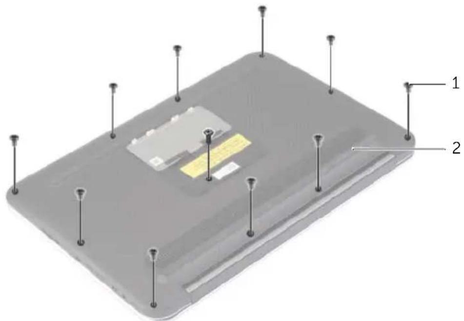
3 Remove the screws that secure the base cover to the palm-rest assembly.
text_image
Diagram of a device component with labeled parts 1 and 2, showing pins and a yellow internal structure.1 screws (11) 2 base cover
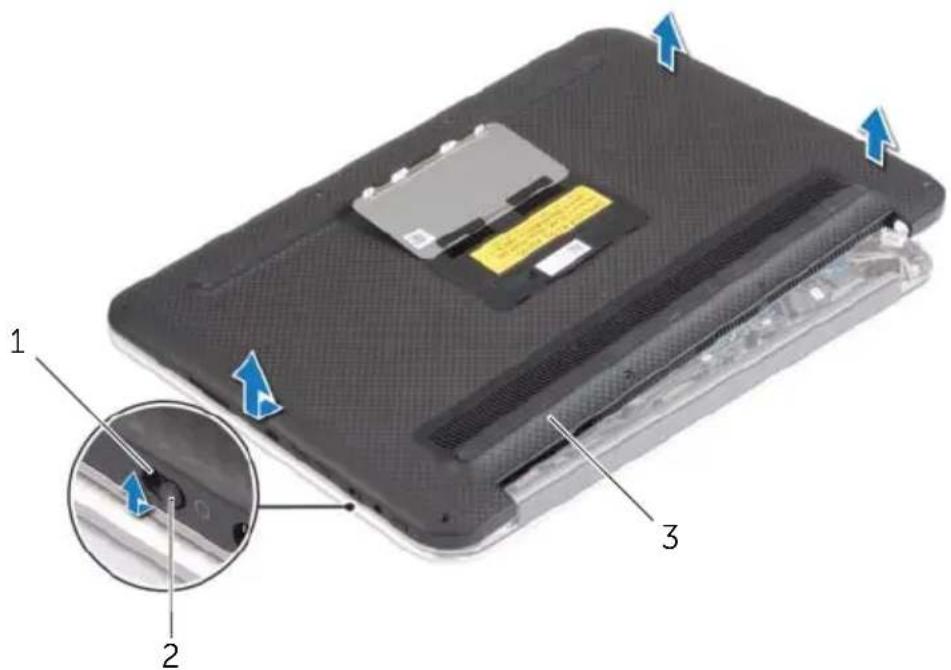
4 Place the computer with the rear side facing you, and starting from the right side, gently pry up the base cover.
5 Lift the base cover at an angle and slide it to release the power-switch slot from the power switch.
text_image
Labeled diagram of a device showing internal components and directional arrows, with numbered parts 1, 2, and 3.1 power-switch slot 2 power switch
3 b a s e c o v e r

WARNING: Before working inside your computer, read the safety information that shipped with your computer and follow the steps in "Before Working Inside Your Computer" on page 7. After working inside your computer, follow the instructions in "After Working Inside Your Computer" on page 9.
For more safety best practices, see the Regulatory Compliance home page at dell.com/regulatory_compliance.
Procedure
1 Slide the power-switch slot into the power switch and place the base cover on the palm-rest assembly.
2 Snap the base cover into place.
3 Replace the screws that secure the base cover to the palm-rest assembly.
4 Turn the system badge over and snap it into place.
Removing the Battery

WARNING: Before working inside your computer, read the safety information that shipped with your computer and follow the steps in "Before Working Inside Your Computer" on page 7. After working inside your computer, follow the instructions in "After Working Inside Your Computer" on page 9.
For more safety best practices, see the Regulatory Compliance home page at dell.com/regulatory_compliance.
Prerequisites
Remove the base cover. See "Removing the Base Cover" on page 10.
Procedure
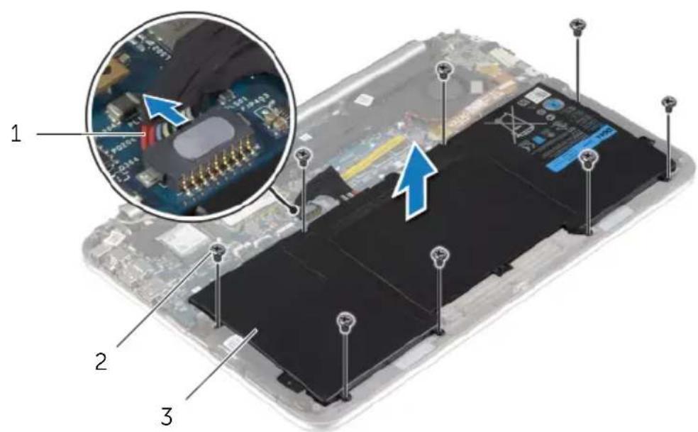
1 Disconnect the battery cable from the system board.
2 Remove the screws that secure the battery to the palm-rest assembly.
3 Lift the battery, along with its cable, off the palm-rest assembly.
text_image
Diagram of an electronic battery pack with labeled components and a magnified inset showing internal circuit board assembly.1 battery cable 2 screws (8)
3 battery
4 Slide and hold the power switch for about five seconds to ground the system board.

WARNING: Before working inside your computer, read the safety information that shipped with your computer and follow the steps in "Before Working Inside Your Computer" on page 7. After working inside your computer, follow the instructions in "After Working Inside Your Computer" on page 9.
For more safety best practices, see the Regulatory Compliance home page at dell.com/regulatory_compliance.
Procedure
1 Align the screw holes on the battery with the screw holes on the palm-rest assembly and place the battery on the palm-rest assembly.
2 Replace the screws that secure the battery to the palm-rest assembly.
3 Connect the battery cable to the system board.
Postrequisites
Replace the base cover. See "Replacing the Base Cover" on page 12.
Removing the Wireless Card

WARNING: Before working inside your computer, read the safety information that shipped with your computer and follow the steps in "Before Working Inside Your Computer" on page 7. After working inside your computer, follow the instructions in "After Working Inside Your Computer" on page 9.
For more safety best practices, see the Regulatory Compliance home page at dell.com/regulatory_compliance.
Prerequisites
1 Remove the base cover. See "Removing the Base Cover" on page 10.
2 Remove the battery. See "Removing the Battery" on page 13.
Procedure
1 Peel off the Mylar and conductive tape that cover the antenna cables.
2 Disconnect the antenna cables from the wireless card.
3 Remove the screw that secures the wireless card to the system board.
4 Slide and remove the wireless card out of the wireless-card connector.
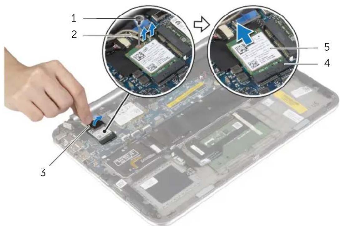
text_image
1 2 3 5 41 screw 2 antenna cables (2)
3 Mylar and conductive tape 4 wireless-card connector
5 wireless card
Replacing the Wireless Card

WARNING: Before working inside your computer, read the safety information that shipped with your computer and follow the steps in "Before Working Inside Your Computer" on page 7. After working inside your computer, follow the instructions in "After Working Inside Your Computer" on page 9.
For more safety best practices, see the Regulatory Compliance home page at dell.com/regulatory_compliance.
Procedure

CAUTION: To avoid damage to the wireless card, do not place any cables under it.
1 Align the notch on the wireless card with the tab on the wireless-card connector.
2 Insert the wireless card into the wireless-card connector and replace the screw that secures the wireless card to the system board.
3 Connect the antenna cables to the wireless card.

NOTE: The color of the antenna cables is visible near the tip of the cables.
The following table provides the antenna-cable color scheme for the wireless card supported by your computer.
Connectors on the wireless card Antenna-cable color
Main (white triangle) white
Auxiliary (black triangle) black
4 Adhere the Mylar and conductive tape on the antenna cables.
Postrequisites
1 Replace the battery. See "Replacing the Battery" on page 14.
2 Replace the base cover. See "Replacing the Base Cover" on page 12.
Removing the mSATA Card

WARNING: Before working inside your computer, read the safety information that shipped with your computer and follow the steps in "Before Working Inside Your Computer" on page 7. After working inside your computer, follow the instructions in "After Working Inside Your Computer" on page 9.
For more safety best practices, see the Regulatory Compliance home page at dell.com/regulatory_compliance.
Prerequisites
1 Remove the base cover. See "Removing the Base Cover" on page 10.
2 Remove the battery. See "Removing the Battery" on page 13.
Procedure
1 Remove the screw that secures the mSATA card to the system board.
2 Slide and remove the mSATA card out of the mSATA-card connector.
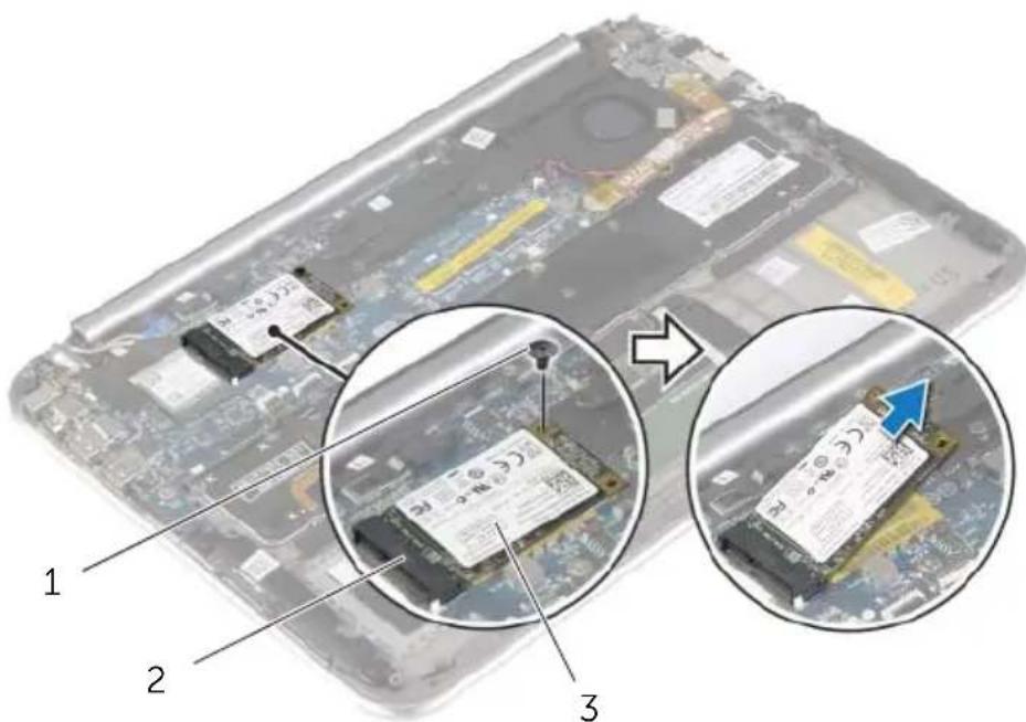
text_image
Laptop screen with labeled components and magnified views showing battery pack installation steps1 screw 2 mSATA-card connector
3 m S A T A c a r d

WARNING: Before working inside your computer, read the safety information that shipped with your computer and follow the steps in "Before Working Inside Your Computer" on page 7. After working inside your computer, follow the instructions in "After Working Inside Your Computer" on page 9.
For more safety best practices, see the Regulatory Compliance home page at dell.com/regulatory_compliance.
Procedure
1 Align the notch on the mSATA card with the tab on the mSATA-card connector.
2 Insert the mSATA card, at an angle, into the mSATA-card connector.
3 Press the other end of the mSATA card down and replace the screw that secures the mSATA card to the system board.
Postrequisites
1 Replace the battery. See "Replacing the Battery" on page 14.
2 Replace the base cover. See "Replacing the Base Cover" on page 12.
Removing the Speakers

WARNING: Before working inside your computer, read the safety information that shipped with your computer and follow the steps in "Before Working Inside Your Computer" on page 7. After working inside your computer, follow the instructions in "After Working Inside Your Computer" on page 9.
For more safety best practices, see the Regulatory Compliance home page at dell.com/regulatory_compliance.
Prerequisites
1 Remove the base cover. See "Removing the Base Cover" on page 10.
2 Remove the battery. See "Removing the Battery" on page 13.
Procedure
1 Lift the connector latch and disconnect the touchpad cable from the system board.
2 Remove the screws that secure the speakers to the palm-rest assembly.
3 Disconnect the speaker cable from the I/O board.
4 Peel off the adhesive foams from the speaker cable, note the routing, and remove the cables from the routing guides.
5 Lift the speakers, along with the speaker cable, off the palm-rest assembly.
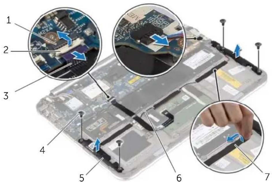
text_image
Laptop keyboard diagram with numbered components and close-up insets showing internal circuitry and component insertion steps| 1 | touchpad-cable connector | 2 | latch |
| 3 | touchpad cable | 4 | screws (4) |
| 5 | speakers (2) | 6 | speaker cable |
| 7 | adhesive foams (3) |

WARNING: Before working inside your computer, read the safety information that shipped with your computer and follow the steps in "Before Working Inside Your Computer" on page 7. After working inside your computer, follow the instructions in "After Working Inside Your Computer" on page 9.
For more safety best practices, see the Regulatory Compliance home page at dell.com/regulatory_compliance.
Procedure
1 Using the alignment posts on the palm-rest assembly, place the speakers on the palm-rest assembly.
2 Replace the screws that secure the speakers to the palm-rest assembly.
3 Route the speaker cable through the routing guides on the palm-rest assembly and adhere the adhesive foams.
4 Connect the speakers cable to the I/O board.
5 Slide the touchpad cable into the touchpad-cable connector and press the connector latch to secure the cable.
Postrequisites
1 Replace the battery. See "Replacing the Battery" on page 14.
2 Replace the base cover. See "Replacing the Base Cover" on page 12.
Removing the Coin-Cell Battery

WARNING: Before working inside your computer, read the safety information that shipped with your computer and follow the steps in "Before Working Inside Your Computer" on page 7. After working inside your computer, follow the instructions in "After Working Inside Your Computer" on page 9.
For more safety best practices, see the Regulatory Compliance home page at dell.com/regulatory_compliance.

CAUTION: Removing the coin-cell battery resets the BIOS settings to default. It is recommended that you note the BIOS settings before removing the coin-cell battery.
Prerequisites
1 Remove the base cover. See "Removing the Base Cover" on page 10.
2 Remove the battery. See "Removing the Battery" on page 13.
Procedure
1 Using the pull tabs, disconnect the I/O-board cable from the I/O board and the system board, and remove the cable.
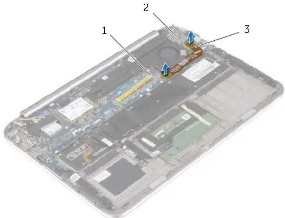
text_image
Labeled diagram of a laptop showing three components: one with blue arrows pointing to a highlighted section.| 1 system board 2 I/O board | ||||||||||||||
| 3 | I | / | O | - | b | o | a | r | d | c | a | b | l | e |
2 Disconnect the coin-cell battery cable from the system board.
3 Note the routing of the coin-cell battery cable and remove the cable from the routing guides.
4 Peel off the coin-cell battery from the keyboard.
5 Lift the coin-cell battery, along with its cable, off the keyboard.
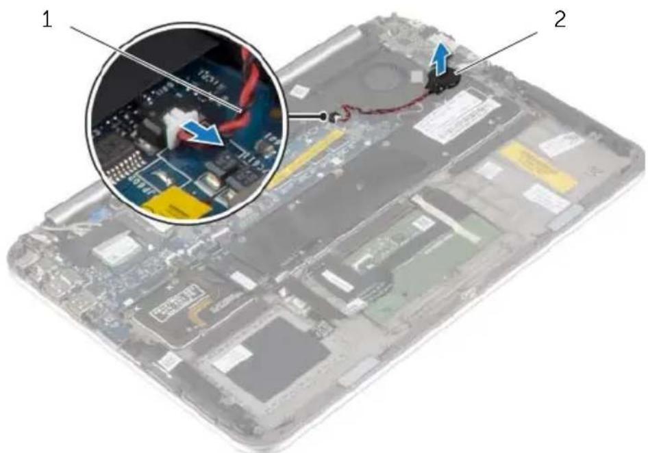
text_image
Laptop interior photo with labeled components and a magnified inset showing internal circuit board wiring1 coin-cell battery cable 2 coin-cell battery
Replacing the Coin-Cell Battery

WARNING: Before working inside your computer, read the safety information that shipped with your computer and follow the steps in "Before Working Inside Your Computer" on page 7. After working inside your computer, follow the instructions in "After Working Inside Your Computer" on page 9.
For more safety best practices, see the Regulatory Compliance home page at dell.com/regulatory_compliance.

WARNING: The battery may explode if installed incorrectly. Replace the battery only with the same or equivalent type. Discard used batteries according to the manufacturer's instructions.
Procedure
1 Adhere the coin-cell battery to the keyboard.
2 Connect the coin-cell battery cable to the system board.
3 Route the coin-cell battery cable through the routing guides.
4 Connect the I/O-board cable to the I/O board and the system board.
Postrequisites
1 Replace the battery. See "Replacing the Battery" on page 14.
2 Replace the base cover. See "Replacing the Base Cover" on page 12.
Removing the I/O Board

WARNING: Before working inside your computer, read the safety information that shipped with your computer and follow the steps in "Before Working Inside Your Computer" on page 7. After working inside your computer, follow the instructions in "After Working Inside Your Computer" on page 9.
For more safety best practices, see the Regulatory Compliance home page at dell.com/regulatory_compliance.
Prerequisites
1 Remove the base cover. See "Removing the Base Cover" on page 10.
2 Remove the battery. See "Removing the Battery" on page 13.
Procedure
1 Disconnect the speaker cable from the I/O board.
2 Using the pull tab, disconnect the I/O-board cable from the system board and the I/O-board.
3 Remove the screws that secure the I/O board to the palm-rest assembly.
4 Lift the I/O board away from the palm-rest assembly.
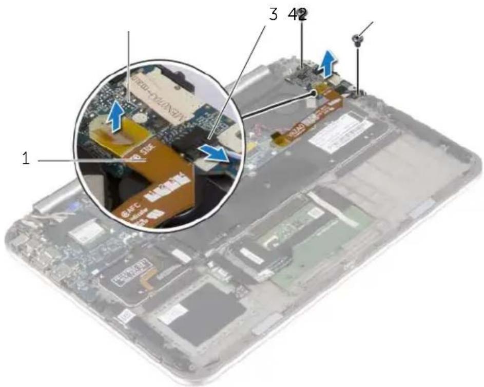
text_image
1 3 42 1 3 421 I/O-board cable 2 I/O board
3 s p e a k e r s c a s c r e w s (12) e 4

WARNING: Before working inside your computer, read the safety information that shipped with your computer and follow the steps in "Before Working Inside Your Computer" on page 7. After working inside your computer, follow the instructions in "After Working Inside Your Computer" on page 9.
For more safety best practices, see the Regulatory Compliance home page at dell.com/regulatory_compliance.
Procedure

NOTE: Make sure that the power switch is in its default position — moved towards the back of the computer — before replacing the I/O board.
1 Align the screw holes on the I/O board with the screw holes on the palm-rest assembly.
2 Replace the screws that secure the I/O board to the palm-rest assembly.
3 Connect the speaker cable to the I/O board.
4 Connect the I/O-board cable to the I/O board and the system board.
Postrequisites
1 Replace the battery. See "Replacing the Battery" on page 14.
2 Replace the base cover. See "Replacing the Base Cover" on page 12.
Removing the Fan

WARNING: Before working inside your computer, read the safety information that shipped with your computer and follow the steps in "Before Working Inside Your Computer" on page 7. After working inside your computer, follow the instructions in "After Working Inside Your Computer" on page 9.
For more safety best practices, see the Regulatory Compliance home page at dell.com/regulatory_compliance.
Prerequisites
1 Remove the base cover. See "Removing the Base Cover" on page 10.
2 Remove the battery. See "Removing the Battery" on page 13.
Procedure
1 Using the pull tabs, disconnect the I/O-board cable from the I/O board and the system board, and remove the cable.
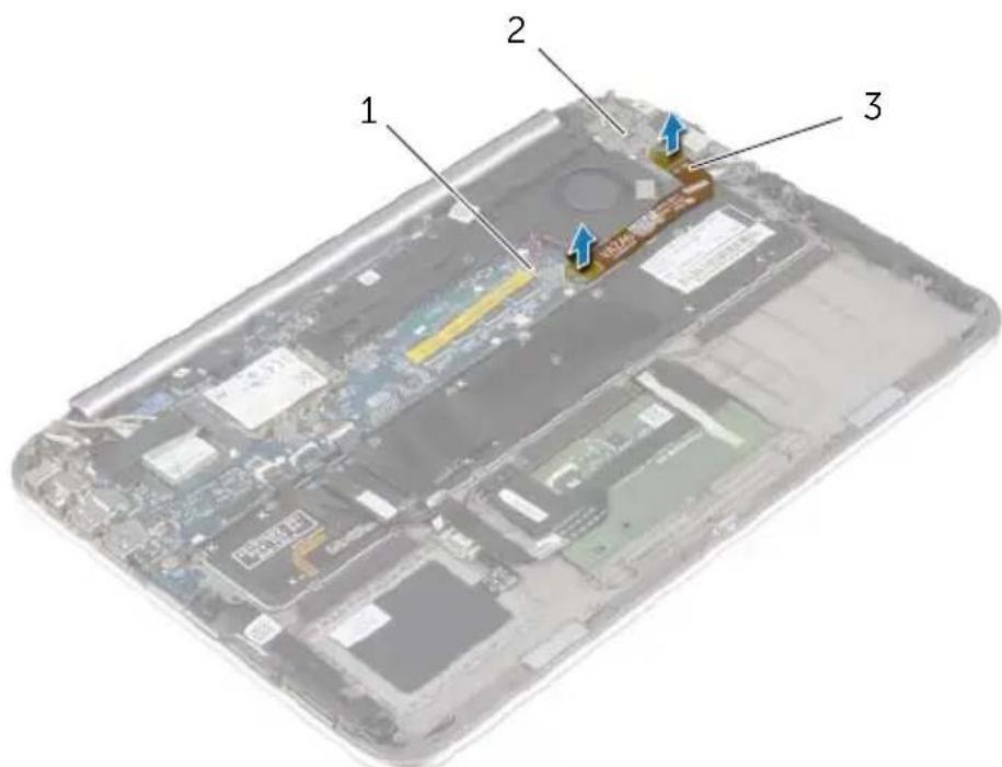
text_image
Laptop interior diagram with numbered components and blue arrows indicating features1 system board 2 I/O board
3 | / O - b o a r d c a b l e
2 Note the routing of the coin-cell battery cable and remove the cable from the routing guides on the fan.
3 Disconnect the fan cable from the system board.
4 Remove the screws that secure the fan to the keyboard.
5 Slide and lift the fan, along with its cable, away from the keyboard.
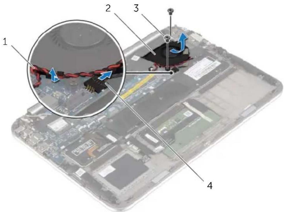
text_image
Labeled diagram of a computer motherboard showing internal components and wiring, with numbered parts 1 to 4.1 coin-cell battery cable 2 fan
3 screws (2) 4 fan cable

WARNING: Before working inside your computer, read the safety information that shipped with your computer and follow the steps in "Before Working Inside Your Computer" on page 7. After working inside your computer, follow the instructions in "After Working Inside Your Computer" on page 9.
For more safety best practices, see the Regulatory Compliance home page at dell.com/regulatory_compliance.
Procedure
1 Slide the tab on the fan under the heat sink and align the screw holes on the fan with the screw holes on the keyboard.
2 Replace the screws that secure the fan to the keyboard.
3 Connect the fan cable to the system board.
4 Route the coin-cell battery cable through the routing guides on the fan.
5 Connect the I/O-board cable to the I/O board and the system board.
Postrequisites
1 Replace the battery. See "Replacing the Battery" on page 14.
2 Replace the base cover. See "Replacing the Base Cover" on page 12.
Removing the Heat Sink

WARNING: Before working inside your computer, read the safety information that shipped with your computer and follow the steps in "Before Working Inside Your Computer" on page 7. After working inside your computer, follow the instructions in "After Working Inside Your Computer" on page 9.
For more safety best practices, see the Regulatory Compliance home page at dell.com/regulatory_compliance.
Prerequisites
1 Remove the base cover. See "Removing the Base Cover" on page 10.
2 Remove the battery. See "Removing the Battery" on page 13.
Procedure
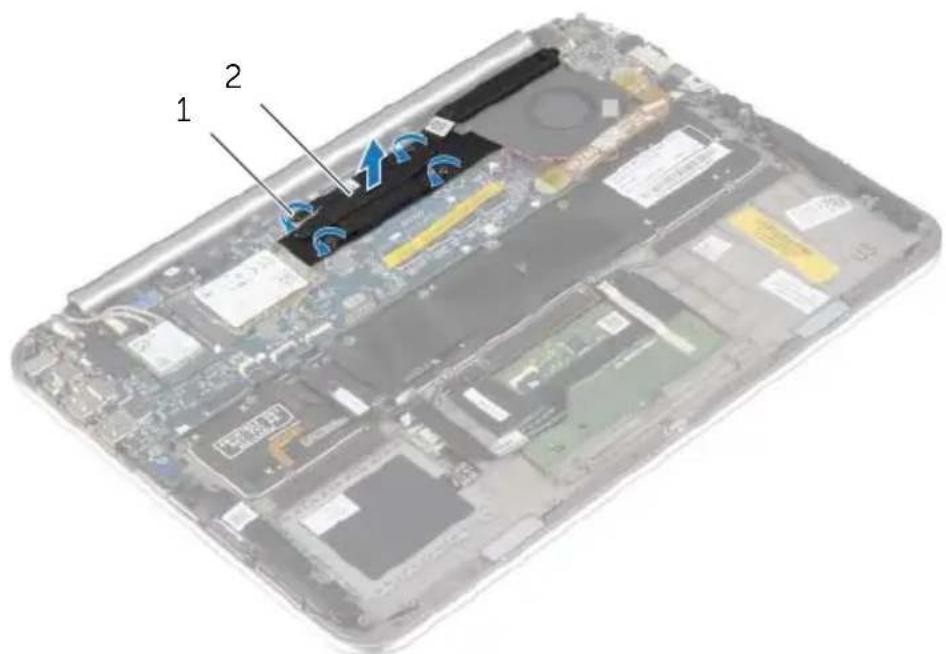
1 In sequential order (indicated on the heat sink), loosen the captive screws that secure the heat sink to the system board.
2 Lift the heat sink off the system board.
text_image
Labeled diagram of a laptop showing internal components with numbered parts and a blue arrow indicating a specific area.1 captive screws (4) 2 heat sink

WARNING: Before working inside your computer, read the safety information that shipped with your computer and follow the steps in "Before Working Inside Your Computer" on page 7. After working inside your computer, follow the instructions in "After Working Inside Your Computer" on page 9.
For more safety best practices, see the Regulatory Compliance home page at dell.com/regulatory_compliance.
Procedure

NOTE: The original thermal grease can be reused, if the original system board and heat sink are reinstalled together. If either the system board or the heat sink is replaced, use the thermal pad provided in the kit to make sure that thermal conductivity is achieved.
1 Align the screws on the heat sink with the screw holes on the system board.
2 In sequential order (indicated on the heat sink), tighten the captive screws that secure the heat sink to the system board.
Postrequisites
1 Replace the battery. See "Replacing the Battery" on page 14.
2 Replace the base cover. See "Replacing the Base Cover" on page 12.
Removing the Power-Adapter Port

WARNING: Before working inside your computer, read the safety information that shipped with your computer and follow the steps in "Before Working Inside Your Computer" on page 7. After working inside your computer, follow the instructions in "After Working Inside Your Computer" on page 9.
For more safety best practices, see the Regulatory Compliance home page at dell.com/regulatory_compliance.
Prerequisites
1 Remove the base cover. See "Removing the Base Cover" on page 10.
2 Remove the battery. See "Removing the Battery" on page 13.
Procedure
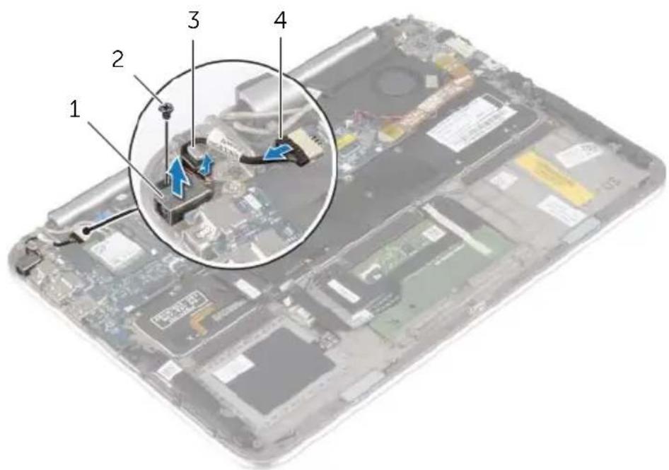
1 Disconnect the power-adapter port cable from the system board.
2 Remove the screw that secures the power-adapter port to the palm-rest assembly.
3 Slide and release the power-adapter port cable from under the display hinge.
4 Lift the power-adapter port off the palm-rest assembly.
text_image
Labeled diagram of a computer motherboard showing numbered components and a magnified inset view with blue arrows indicating flow or movement.| 1 | power-adapter port | 2 | screw |
| 3 | display hinge | 4 | power-adapter port cable |

WARNING: Before working inside your computer, read the safety information that shipped with your computer and follow the steps in "Before Working Inside Your Computer" on page 7. After working inside your computer, follow the instructions in "After Working Inside Your Computer" on page 9.
For more safety best practices, see the Regulatory Compliance home page at dell.com/regulatory_compliance.
Procedure
1 Slide the power-adapter port cable under the display hinge.
2 Align the screw hole on the power-adapter port with the screw hole on the palm-rest assembly.
3 Replace the screw that secures the power-adapter port to the palm-rest assembly.
4 Connect the power-adapter port cable to the system board.
Postrequisites
1 Replace the battery. See "Replacing the Battery" on page 14.
2 Replace the base cover. See "Replacing the Base Cover" on page 12.

WARNING: Before working inside your computer, read the safety information that shipped with your computer and follow the steps in "Before Working Inside Your Computer" on page 7. After working inside your computer, follow the instructions in "After Working Inside Your Computer" on page 9.
For more safety best practices, see the Regulatory Compliance home page at dell.com/regulatory_compliance.
Prerequisites
1 Remove the base cover. See "Removing the Base Cover" on page 10.
2 Remove the battery. See "Removing the Battery" on page 13.
3 Remove the wireless card. See "Removing the Wireless Card" on page 15.
4 Remove the mSATA card. See "Removing the mSATA Card" on page 17.
5 Remove the fan. See "Removing the Fan" on page 26.
6 Remove the heat sink. See "Removing the Heat Sink" on page 29.
Procedure

NOTE: Replacing the system board removes any changes you have made to the BIOS using System Setup. Enter the Service Tag of your computer in the BIOS and make the desired changes again after you replace the system board.
For more information on entering the Service Tag in the BIOS, see "Replacing the System Board" on page 36.

NOTE: Before disconnecting the cables from the system board, note the location of the connectors so that you can reconnect them correctly after you replace the system board.
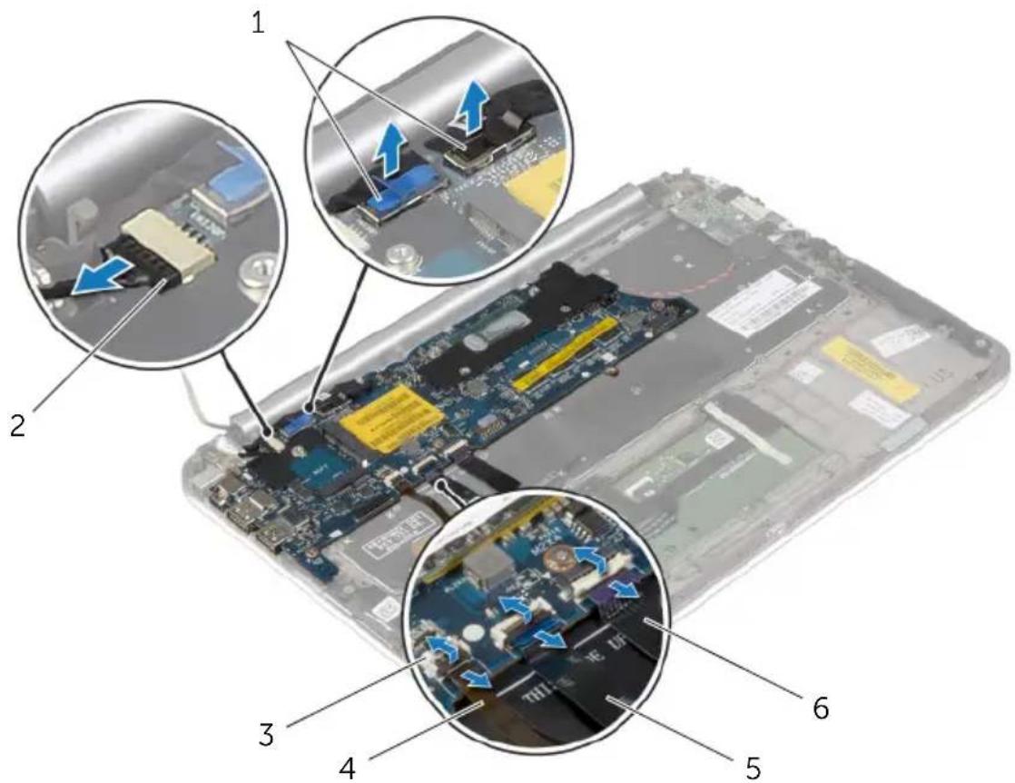
1 Disconnect the power-adapter port cable from the system board.
2 Using the pull tabs, disconnect the display cables from the system board.
3 Lift the connector latches, and using the pull tabs, disconnect the keyboard-backlight cable, the NFC cable, and the touchpad cable from the system board.
text_image
Labeled diagram of a computer motherboard showing six key components with arrows indicating assembly or movement.1 display cables (2) 2 power-adapter port cable
3 connector latches (3) 4 keyboard-backlight cable
5 NFC cable 6 touchpad cable
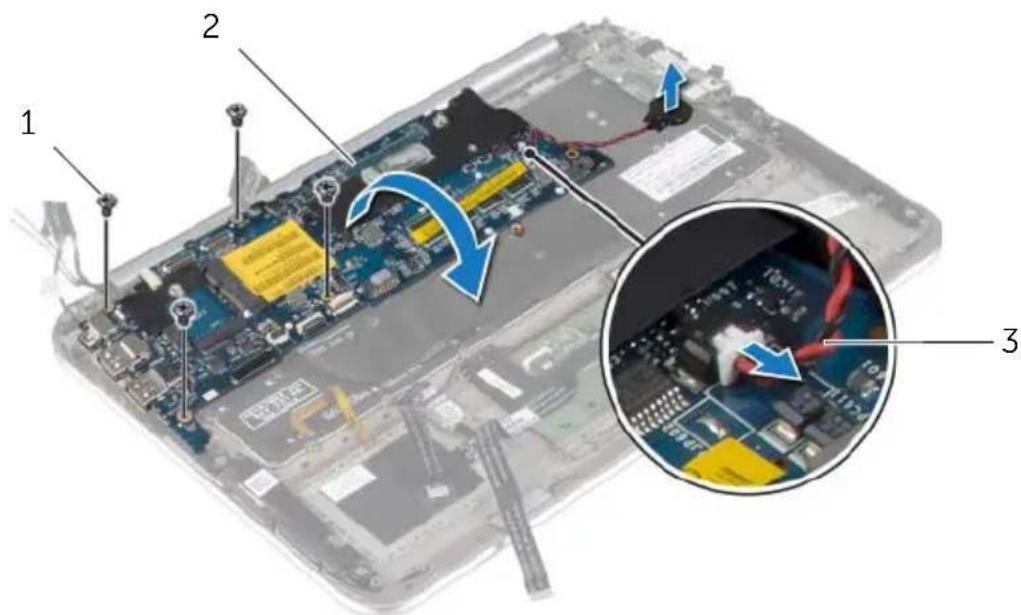
4 Disconnect the coin-cell battery cable from the system board.
5 Remove the screws that secure the system board to the palm-rest assembly.
6 Carefully lift the system board and turn it over.
text_image
Laptop interior with labeled components and a magnified inset showing internal circuit board connections1 screws (4) 2 system board
3 coin-cell battery cable
7 Lift the connector latch and disconnect the keyboard cable from the system board.
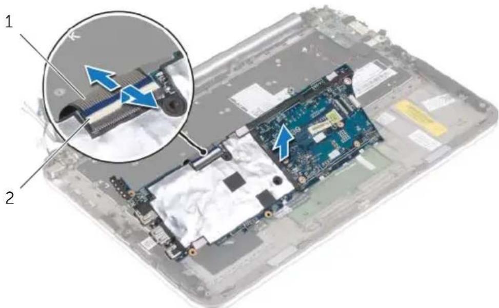
text_image
Laptop screen with close-up of internal components and blue arrows indicating disassembly or repair steps1 keyboard cable 2 connector latch
8 Lift the system board off the palm-rest assembly.

WARNING: Before working inside your computer, read the safety information that shipped with your computer and follow the steps in "Before Working Inside Your Computer" on page 7. After working inside your computer, follow the instructions in "After Working Inside Your Computer" on page 9.
For more safety best practices, see the Regulatory Compliance home page at dell.com/regulatory_compliance.
Procedure
1 Slide the keyboard cable into the keyboard-cable connector and press down on the connector latch to secure the cable.

CAUTION: Make sure that no cables are placed under the system board.
2 Turn the system board over and align the screw holes on the system board with the screw holes on the palm-rest assembly.
3 Replace the screws that secure the system board to the palm-rest assembly.
4 Connect the coin-cell battery cable to the system board.
5 Slide the keyboard-backlight cable, the NFC cable, and the touchpad cable in the respective connectors, and press down on the connector latches to secure the cables.
6 Connect the display cables to the system board.

NOTE: When connecting the display cables to the system board, match the labels (L and R) on the display cables to the labels on the system board.
7 Connect the power-adapter port cable to the system board.
Postrequisites
1 Replace the heat sink. See "Replacing the Heat Sink" on page 30.
2 Replace the fan. See "Replacing the Fan" on page 28.
3 Replace the mSATA card. See "Replacing the mSATA Card" on page 18.
4 Replace the wireless card. See "Replacing the Wireless Card" on page 16.
5 Replace the battery. See "Replacing the Battery" on page 14.
6 Replace the base cover. See "Replacing the Base Cover" on page 12.
Entering the Service Tag in the BIOS
1 Turn on the computer.
2 At the Dell logo, press
3 Navigate to the Main tab and type the Service Tag in the Service Tag field.
Removing the Display Assembly

WARNING: Before working inside your computer, read the safety information that shipped with your computer and follow the steps in "Before Working Inside Your Computer" on page 7. After working inside your computer, follow the instructions in "After Working Inside Your Computer" on page 9.
For more safety best practices, see the Regulatory Compliance home page at dell.com/regulatory_compliance.
Prerequisites
1 Remove the base cover. See "Removing the Base Cover" on page 10.
2 Remove the battery. See "Removing the Battery" on page 13.
3 Remove the heat sink. See "Removing the Heat Sink" on page 29.
Procedure
1 Disconnect the power-adapter port cable from the system board and remove the cable from the display hinge.
2 Peel off the Mylar and conductive tape that cover the antenna cables and disconnect the antenna cables from the wireless card.
3 Using the pull tabs, disconnect the display cables from the system board.
4 Note the routing of the display-cables and remove the cables from the routing guides.
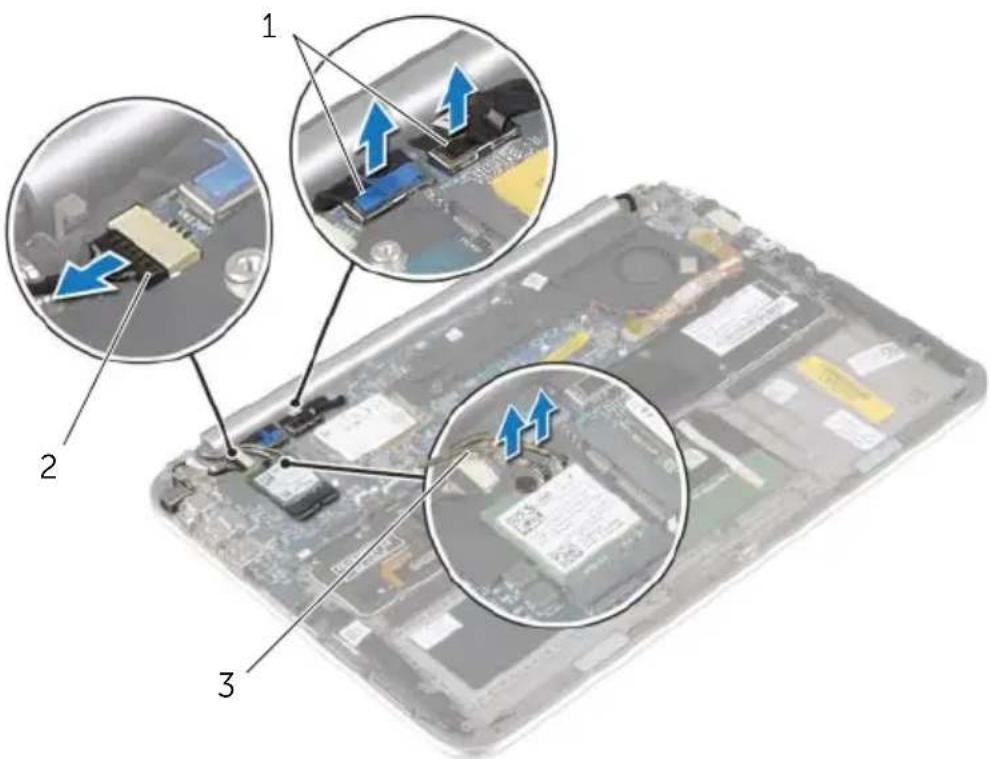
text_image
Laptop screen with three labeled close-up views showing internal components and blue arrows indicating motion or movement.1 display cables (2) 2 power-adapter port cable
3 antenna cables (2)
5 Remove the screws that secure the display assembly to the palm-rest assembly.
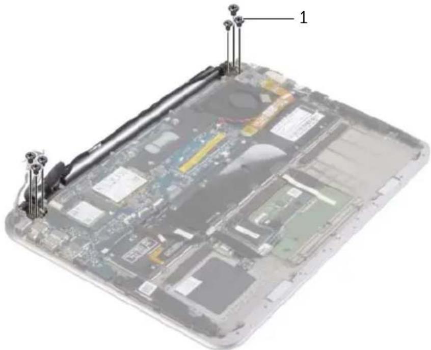
natural_image
Laptop screen with visible circuit board and labeled components (no text or symbols beyond labels)1 s c r e w s ( 6 )
6 Carefully rotate the palm-rest assembly up, and then slide the palm-rest assembly to release the tabs on the palm-rest assembly from the display hinges.
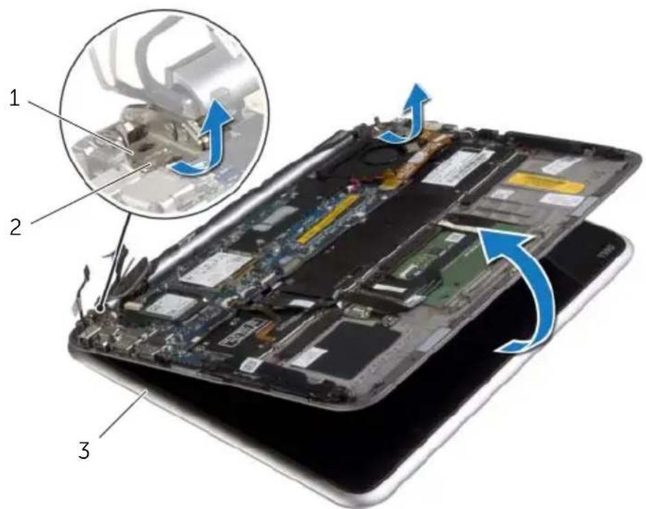
text_image
Laptop screen with open circuit board and mechanical components, showing disassembly steps labeled 1, 2, and 3.1 display hinges (2) 2 tabs
3 display assembly

WARNING: Before working inside your computer, read the safety information that shipped with your computer and follow the steps in "Before Working Inside Your Computer" on page 7. After working inside your computer, follow the instructions in "After Working Inside Your Computer" on page 9.
For more safety best practices, see the Regulatory Compliance home page at dell.com/regulatory_compliance.
Procedure
1 Slide the tab on the palm-rest assembly under the display hinges to align the palm-rest assembly and then place it on the display assembly.
2 Rotate the display hinges down to insert the tabs on the palm-rest assembly into the slots on the display hinges.
3 Replace the screws that secure the display assembly to the palm-rest assembly.
4 Connect the power-adapter port cable and display cables to the system board.

NOTE: When connecting the display cables to the system board, match the labels (L and R) on the display cables to the labels on the system board.
5 Connect the antenna cables to the wireless card, and then adhere the Mylar and conductive tape over the antenna cables.
Postrequisites
1 Replace the heat sink. See "Replacing the Heat Sink" on page 30.
2 Replace the battery. See "Replacing the Battery" on page 14.
3 Replace the base cover. See "Replacing the Base Cover" on page 12.

WARNING: Before working inside your computer, read the safety information that shipped with your computer and follow the steps in "Before Working Inside Your Computer" on page 7. After working inside your computer, follow the instructions in "After Working Inside Your Computer" on page 9.
For more safety best practices, see the Regulatory Compliance home page at dell.com/regulatory_compliance.
Prerequisites
1 Remove the base cover. See "Removing the Base Cover" on page 10.
2 Remove the battery. See "Removing the Battery" on page 13.
Procedure
1 Turn the computer over and open the display as far as possible.
2 Rotate the display panel and remove the screws that secure the display back-cover to the display panel.

text_image
Diagram of a laptop with labeled parts and directional arrows indicating movement or navigation1 display panel 2 screws (8)
3 Rotate the display and remove the screws that secure the display back-cover to the display panel.
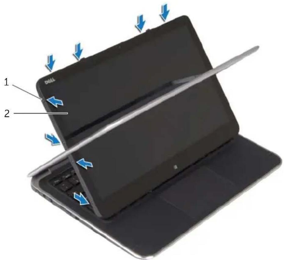
text_image
1 21 screws (8)
2 display panel
4 Starting from the corners, gently pry the display back-cover from the display panel.

WARNING: Before working inside your computer, read the safety information that shipped with your computer and follow the steps in "Before Working Inside Your Computer" on page 7. After working inside your computer, follow the instructions in "After Working Inside Your Computer" on page 9.
For more safety best practices, see the Regulatory Compliance home page at dell.com/regulatory_compliance.
Procedure
1 Place the display back-cover on the display panel and snap it in place.
2 Replace the screws that secure the display back-cover to the display panel.
Postrequisites
1 Replace the battery. See "Replacing the Battery" on page 14.
2 Replace the base cover. See "Replacing the Base Cover" on page 12.
Removing the Camera Module

WARNING: Before working inside your computer, read the safety information that shipped with your computer and follow the steps in "Before Working Inside Your Computer" on page 7. After working inside your computer, follow the instructions in "After Working Inside Your Computer" on page 9.
For more safety best practices, see the Regulatory Compliance home page at dell.com/regulatory_compliance.
Prerequisites
1 Remove the base cover. See "Removing the Base Cover" on page 10.
2 Remove the battery. See "Removing the Battery" on page 13.
3 Remove the display back-cover. See "Removing the Display Back-Cover" on page 40.
Procedure
1 Remove the screws that secure the camera module to the display panel.
2 Turn the camera module over and disconnect the camera cable from the camera module.
3 Lift the camera module off the display panel.
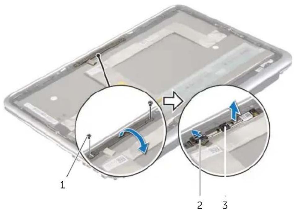
text_image
Diagram showing a device with labeled parts and directional arrows indicating motion or assembly steps1 screws (2) 2 camera cable
3 c a m e r a m o d u l e

WARNING: Before working inside your computer, read the safety information that shipped with your computer and follow the steps in "Before Working Inside Your Computer" on page 7. After working inside your computer, follow the instructions in "After Working Inside Your Computer" on page 9.
For more safety best practices, see the Regulatory Compliance home page at dell.com/regulatory_compliance.
Procedure
1 Connect the camera cable to the camera module.
2 Use the alignment posts on the display panel to place the camera module on the display panel.
3 Align the screw holes on the camera module with the screw holes on the display panel.
4 Replace the screws that secure the camera module to the display panel.
Postrequisites
1 Replace the display back-cover. See "Replacing the Display Back-Cover" on page 42.
2 Replace the battery. See "Replacing the Battery" on page 14.
3 Replace the base cover. See "Replacing the Base Cover" on page 12.
Removing the Windows-Button Board

WARNING: Before working inside your computer, read the safety information that shipped with your computer and follow the steps in "Before Working Inside Your Computer" on page 7. After working inside your computer, follow the instructions in "After Working Inside Your Computer" on page 9.
For more safety best practices, see the Regulatory Compliance home page at dell.com/regulatory_compliance.
Prerequisites
1 Remove the base cover. See "Removing the Base Cover" on page 10.
2 Remove the battery. See "Removing the Battery" on page 13.
3 Remove the display back-cover. See "Removing the Display Back-Cover" on page 40.
Procedure
1 Remove the screws that secure the Windows-button board to the display panel.
2 Turn the Windows-button board over and disconnect the Windows-button board cable from the board.
3 Lift the Windows-button board off the display panel.
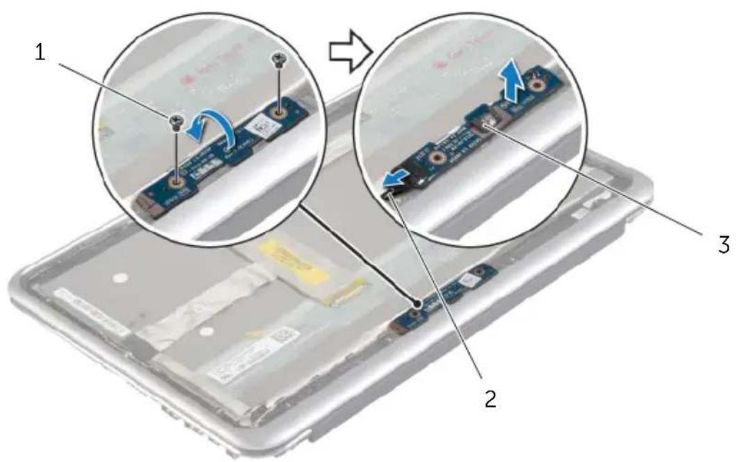
text_image
Diagram showing a device's internal components with numbered annotations and magnified views highlighting changes in the circuit board.1 screws (2) 2 Windows-button board cable
3 Windows-button board

WARNING: Before working inside your computer, read the safety information that shipped with your computer and follow the steps in "Before Working Inside Your Computer" on page 7. After working inside your computer, follow the instructions in "After Working Inside Your Computer" on page 9.
For more safety best practices, see the Regulatory Compliance home page at dell.com/regulatory_compliance.
Procedure
1 Connect the Windows-button board cable to the Windows-button board.
2 Use the alignment posts on the display panel to place the Windows-button board on the display panel.
3 Align the screw holes on the Windows-button board with the screw holes on the display panel.
4 Replace the screws that secure the Windows-button board to the display panel.
Postrequisites
1 Replace the display back-cover. See "Replacing the Display Back-Cover" on page 42.
2 Replace the battery. See "Replacing the Battery" on page 14.
3 Replace the base cover. See "Replacing the Base Cover" on page 12.
Removing the Display Panel

WARNING: Before working inside your computer, read the safety information that shipped with your computer and follow the steps in "Before Working Inside Your Computer" on page 7. After working inside your computer, follow the instructions in "After Working Inside Your Computer" on page 9.
For more safety best practices, see the Regulatory Compliance home page at dell.com/regulatory_compliance.
Prerequisites
1 Remove the base cover. See "Removing the Base Cover" on page 10.
2 Remove the battery. See "Removing the Battery" on page 13.
3 Remove the display back-cover. See "Removing the Display Back-Cover" on page 40.
4 Remove the camera module. See "Removing the Camera Module" on page 43.
5 Remove the Windows-button board. See "Removing the Windows-Button Board" on page 45.
Procedure
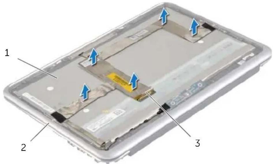
1 Peel off the tape and disconnect the display cable from the display panel.
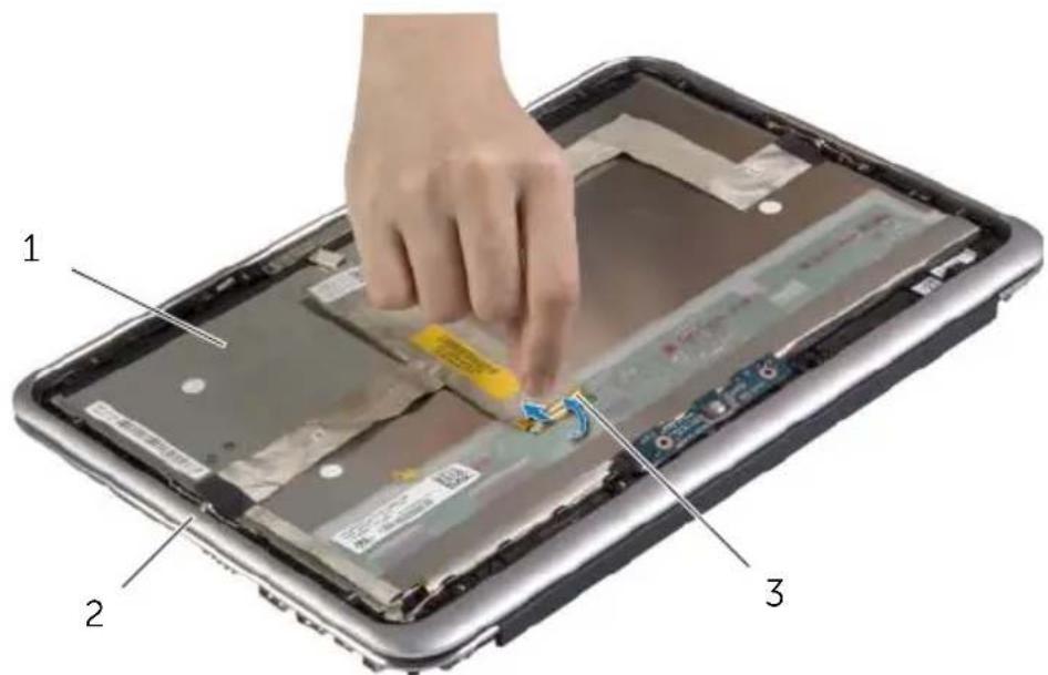
text_image
Labeled diagram of a device showing a hand pressing down on a circuit board with numbered parts 1, 2, and 3.1 display panel 2 display bezel
3 display cable

CAUTION: Do not remove the display cable from the display bezel.
2 Peel off the display cable from the display panel.
text_image
1 2 31 display panel 2 display bezel
3 display cable
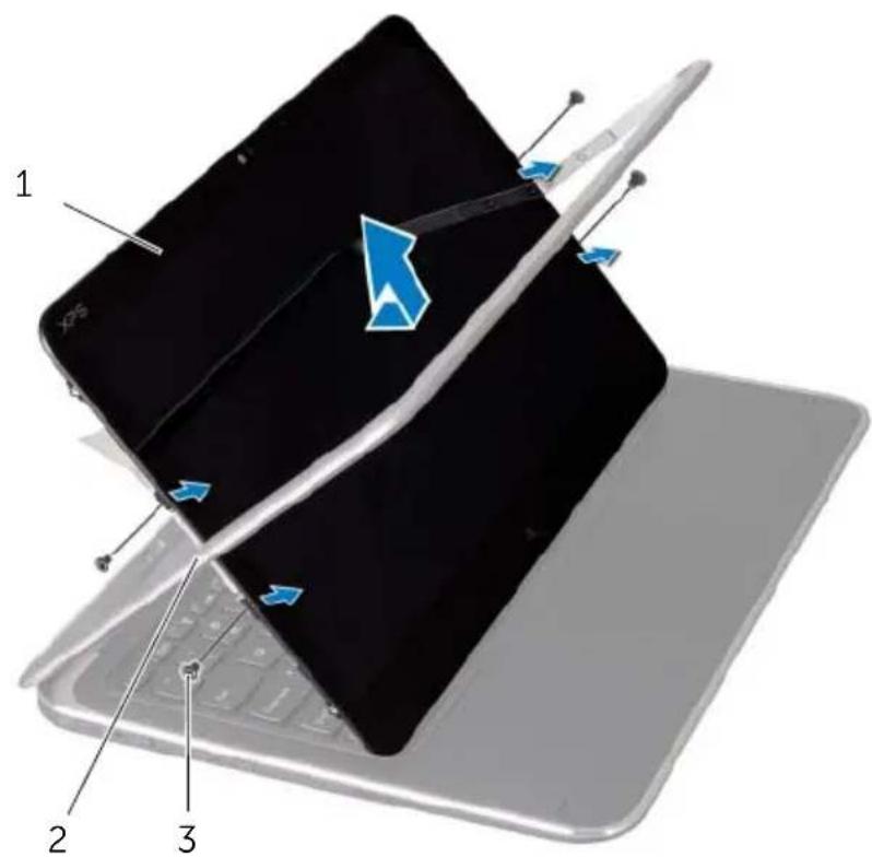
3 Remove the screws that secure the display panel to the display bezel.
4 Slide and lift the display panel off the display bezel.
text_image
Laptop screen with labeled parts showing a device and a blue arrow indicating motion or change.1 display panel 2 display bezel
3 s c r e w s ( 4 )

WARNING: Before working inside your computer, read the safety information that shipped with your computer and follow the steps in "Before Working Inside Your Computer" on page 7. After working inside your computer, follow the instructions in "After Working Inside Your Computer" on page 9.
For more safety best practices, see the Regulatory Compliance home page at dell.com/regulatory_compliance.
Procedure
1 Slide the display panel into the display bezel and align the screw holes on the display panel with the screw holes on the display bezel.
2 Replace the screws that secure the display panel to the display bezel.
3 Adhere the display cable to the display panel.
4 Connect the display cable to the display panel and adhere the tape.
Postrequisites
1 Replace the Windows-button board. See "Replacing the Windows-Button Board" on page 46.
2 Replace the camera module. See "Replacing the Camera Module" on page 44.
3 Replace the display back-cover. See "Replacing the Display Back-Cover" on page 42.
4 Replace the battery. See "Replacing the Battery" on page 14.
5 Replace the base cover. See "Replacing the Base Cover" on page 12.

WARNING: Before working inside your computer, read the safety information that shipped with your computer and follow the steps in "Before Working Inside Your Computer" on page 7. After working inside your computer, follow the instructions in "After Working Inside Your Computer" on page 9.
For more safety best practices, see the Regulatory Compliance home page at dell.com/regulatory_compliance.
Prerequisites
1 Remove the base cover. See "Removing the Base Cover" on page 10.
2 Remove the battery. See "Removing the Battery" on page 13.
3 Remove the I/O board. See "Removing the I/O Board" on page 24.
4 Remove the coin-cell battery. See "Removing the Coin-Cell Battery" on page 21.
5 Remove the fan. See "Removing the Fan" on page 26.
6 Remove the mSATA card. See "Removing the mSATA Card" on page 17.
Procedure
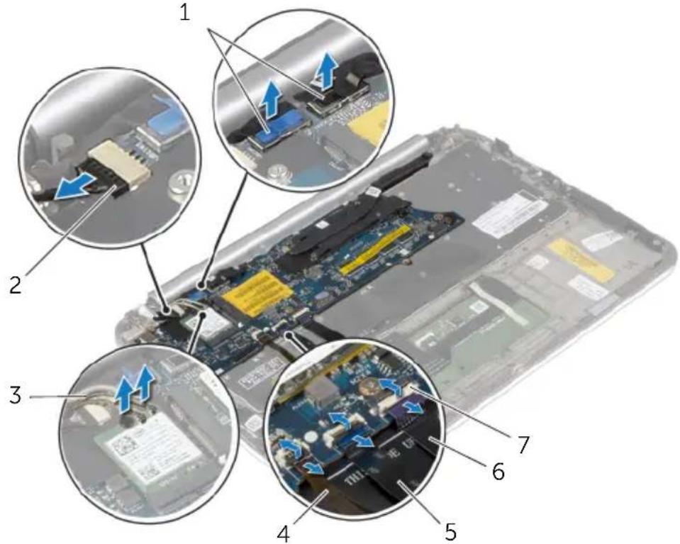
1 Disconnect the display cables and the power-adapter port cable from the system board.
2 Peel off the Mylar and conductive tape that cover the antenna cables and disconnect the antenna cables from the wireless card.
3 Lift the connector latches, and using the pull tabs, disconnect the keyboard-backlight cable, the NFC cable, and the touchpad cable from the system board.
text_image
Laptop interior with numbered annotations indicating component locations and directional arrows for assembly or repair.| 1 display cables (2) 2 power-adapter port cable |
| 3 antenna cables (2) 4 keyboard-backlight cable |
| 5 NFC cable 6 touchpad cable |
| 7 connector latches (3) |
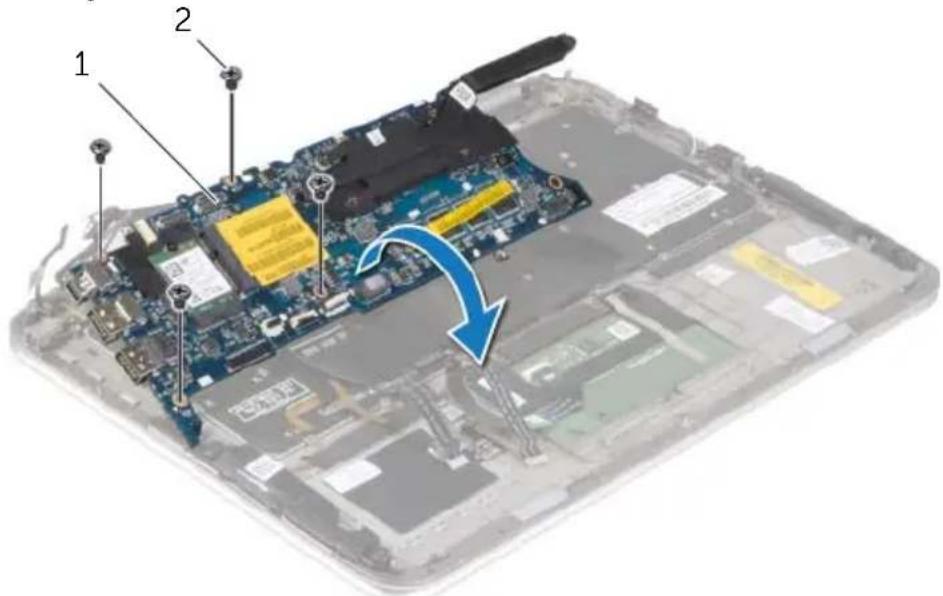
4 Remove the screws that secure the system board to the palm-rest assembly.
5 Carefully lift the system board and turn it over.
text_image
Laptop screen with labeled components and a blue arrow indicating a disassembly or repair process.1 system board 2 screws (4)
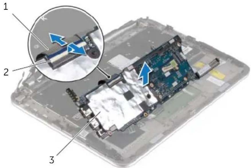
6 Lift the connector latch and disconnect the keyboard cable from the system board, and then lift the system board off the palm-rest assembly.
text_image
Labeled diagram of a computer motherboard showing internal components and a magnified view of the circuit board with blue arrows indicating flow or movement.1 keyboard cable 2 connector latch
3 k e y b o a r d
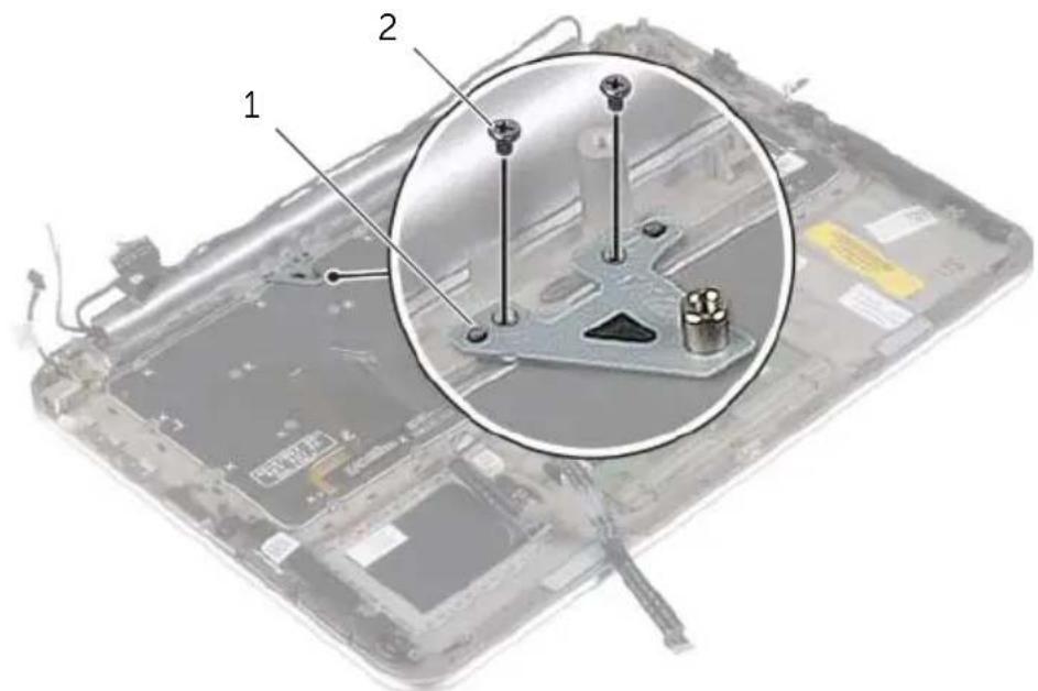
7 Remove the screws that secure the mSATA bracket to the palm-rest assembly and remove the bracket.
text_image
Labeled diagram of a computer motherboard showing parts 1 and 2 with screw holes and battery pack assembly1 mSATA bracket 2 screws (2)

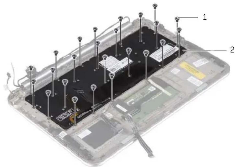
CAUTION: The keycaps on the keyboard are fragile, easily dislodged, and time-consuming to replace. Be careful when removing and handling the keyboard.
8 Remove the screws that secure the keyboard to the palm-rest assembly.
9 Lift the keyboard off the palm-rest assembly.
text_image
Technical diagram of a tablet module with labeled components and wiring, showing internal circuitry and battery pack layout.1 screws (24) 2 keyboard

WARNING: Before working inside your computer, read the safety information that shipped with your computer and follow the steps in "Before Working Inside Your Computer" on page 7. After working inside your computer, follow the instructions in "After Working Inside Your Computer" on page 9.
For more safety best practices, see the Regulatory Compliance home page at dell.com/regulatory_compliance.
Procedure

CAUTION: Make sure that no cables are placed under the keyboard.
1 Insert the key caps into the slots on the palm-rest assembly and align the screw holes on the keyboard with the screw holes on the palm-rest assembly.
2 Replace the screws that secure the keyboard to the palm-rest assembly.
3 Align the screw holes on the mSATA bracket with the screw holes on the palm-rest assembly.
4 Replace the screws that secure the mSATA bracket to the palm-rest assembly.
5 Slide the keyboard cable into the keyboard-cable connector and press down on the connector latch to secure the cable.

CAUTION: Make sure that no cables are placed under the system board.
6 Turn the system board over and align the screw holes on the system board with the screw holes on the palm-rest assembly.
7 Replace the screws that secure the system board to the palm-rest assembly.
8 Connect the display cables to the system board.

NOTE: When connecting the display cables to the system board, match the labels (L and R) on the display cables to the labels on the system board.
9 Connect the power-adapter port cable to the system board.
10 Connect the antenna cables to the wireless card, and adhere the Mylar and conductive tape over the antenna cables.
11 Slide the keyboard-backlight cable, the NFC cable, and the touchpad cable in the respective connectors, and press down on the connector latches to secure the cables.
Postrequisites
1 Replace the mSATA card. See "Replacing the mSATA Card" on page 18.
2 Replace the fan. See "Replacing the Fan" on page 28.
3 Replace the coin-cell battery. See "Replacing the Coin-Cell Battery" on page 23.
4 Replace the I/O board. See "Replacing the I/O Board" on page 25.
5 Replace the battery. See "Replacing the Battery" on page 14.
6 Replace the base cover. See "Replacing the Base Cover" on page 12.
You may need to flash (update) the BIOS when an update is available or when you replace the system board. To flash the BIOS:
1 Turn on the computer.
2 Go to dell.com/support.
3 If you have your computer's Service Tag, type your computer's Service Tag and click Submit.
If you do not have your computer's Service Tag, click Detect Service Tag to allow automatic detection of the Service Tag.

NOTE: If the Service Tag cannot be detected automatically, select your product under the product categories.
4 Click Drivers and Downloads.
5 In the Operating System drop-down, select the operating system installed on your computer.
6 Click BIOS.
7 Click Download File to download the latest version of the BIOS for your computer.
8 On the next page, select Single-file download and click Continue.
9 Save the file and once the download is complete, navigate to the folder where you saved the BIOS update file.
10 Double-click the BIOS update file icon and follow the instructions on the screen.