Sensor - Bike computer TREK - Free user manual and instructions
Find the device manual for free Sensor TREK in PDF.


| Product Type | Bike Computer |
| Brand | Trek |
| Model | Sensor |
| Dimensions (approx.) | 5.0 x 4.0 x 2.0 cm |
| Weight (approx.) | 50 g |
| Power Supply | 1x CR2032 battery (3V) |
| Display Type | LCD |
| Functions | Current speed, average speed, maximum speed, trip distance, odometer, ride time, clock |
| Speed Sensor | Wireless (cadence/speed sensor not included) |
| Mounting | Handlebar mount (included) |
| Water Resistance | IPX4 (splash-proof) |
| Battery Life | Approximately 12 months (based on 1 hour daily use) |
| Auto Start/Stop | Yes (based on wheel rotation) |
| Wheel Size Setting | Manual (wheel circumference input) |
| Maintenance | Clean with a soft dry cloth; avoid contact with solvents |
| Safety | Ensure secure mounting to prevent detachment while riding |
| Spare Parts | Battery (CR2032); replacement mount and zip ties available |
| Repairability | Battery user-replaceable; other repairs by authorized service |
| General Information | Compatible with standard bike computer mounts; 6-page user manual available for download |
Frequently Asked Questions - Sensor TREK
User questions about Sensor TREK
0 question about this device. Answer the ones you know or ask your own.
Ask a new question about this device
Download the instructions for your Bike computer in PDF format for free! Find your manual Sensor - TREK and take your electronic device back in hand. On this page are published all the documents necessary for the use of your device. Sensor by TREK.
USER MANUAL Sensor TREK
Your Trek Sensor Computer is guaranteed for 2 years against defects in workmanship or materials. If you experience problems refer to the suggestions in the troubleshooting guide in this manual. If this does not solve your problem, please return the computer to your authorized Trek
Dealer or send the computer postage paid to:
Trek Bicycle Corporation
Attn. Computer Warranty Dept.
801 W Madison Street
Waterloo, WI 53594 USA
TREK UK
Attn. Computer Warranty Dept.
15 Old Bridge Way
Bedfordshire, SG17 5H0 ENGLAND
Please include the following:
-
The complete computer (wiring, etc.)
-
A copy of your sales receipt
-
A brief explanation of the problem
-
Your return address
For 2 years from the date of purchase, a replacement computer of the same model will be sent to you postage paid by
Trek Bicycle Corporation.
Sensor Cycling Computer
Owners Manual
TREK OWNERS MAUAL
Congratulations and thank you for purchasing the Trek Sensor Bicycling Computer! The New Trek Sensor represents the latest in bicycle computer technology, concepts with features that can greatly enhance the riding experience of any cyclist, whether they are a recreational rider or a top notch racer. The Trek Sensor may actually change the way you ride your bicycle!
Please read this instruction manual carefully and save this manual for future reference.
Precautions
Remember to watch the road while riding. Watching your bicycle computer makes it difficult to see upcoming obstacles. Awareness of potential road, trial, or traffic problems should be your main concern.
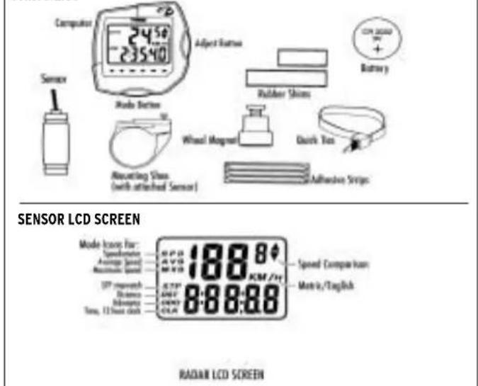
PARTS LIST
text_image
Computer 2450 23540 Adjust Camera Battery Sensor Mode Button Wheel Mirror Duck Top Mounting Shock (with attached Sensor) Adhesive Strips SENSOR LCD SCREEN Mode Icon For: Speedometer Average Speed Maximum Speed UP shipments Balance Continuous Time, 12 Hour clock 188 KM /Hz Speed Comparison Max/Min/English 888:88 RADIAN LCD SCREEN
Never place fingers near the spokes of a rotating wheel or other moving parts which could cause injury. Watch where you are going when riding your bicycle. Inattention may cause a loss of control resulting in personal injury.
COMPUTER FUNCTIONS
Speedometer Display (SPD)
Current riding speed is indicated on the top line of the display with the SPD icon. Instantaneous speed has a display range of 2.5 - 99.5 M/h (4 - 99.5 Km/h).
Automatic Timer Stopwatch (ATM)
The Automatic Timer Stopwatch is displayed on the lower line with the ATM icon. The ATM stopwatch is automatically activated by wheel movement. It cannot be manually turned on or off, and records only the time spend actually riding. To clear stored information and get ready for your next ride, enter SPD/ATM display mode and press both keys for over 2 seconds. This will clear all resetable functions (ATM, DST, AVS & MXS).
Speed Comparison Display
When riding, a + or - icon will appear to the right of the current Speed display. A + icon indicates that your current speed is faster than your recorded average speed. A - icon means you are traveling slower than your recorded average speed.
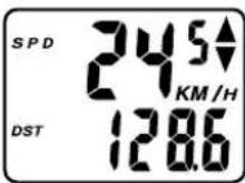
Trip Distance (DST)
Trip Distance is displayed on the lower line, indicated by the DST icon. Trip distance is tied to the ATM stopwatch, and records automatically when riding. Trip Distance records up to 999.9 miles (or Kilometers), with a resolution of 0.1 miles/kilometers.
Average Speed (AVS)
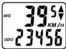
Average Speed is displayed in 0.1 mi/Km increments on the upper line, indicated by the AVS icon. AVS is calculated with the Auto Timer Stopwatch and is the average speed only for time spent actually riding.
Odometer (ODO)
The cumulative distance traveled for all rides is displayed on the lower line, indicated by the ODO icon. Total Odometer can be cleared to 0 by pressing the All Clear button on the bottom of the computer or by removing and re-installing the battery.
Maximum Speed (MXS)
The Maximum Speed reached during a ride is displayed in 0.1 mi/Km increments on the top line, with the MXS icon. Maximum Speed is stored in memory and is updated each time a new, higher speed is reached.
CLOCK (CLK)
The 12 hour clock is displayed on the lower line, indicated by the CLK icon.
ATM "Lap Timer" Display
A unique ATM "Lap Timer" display allows you to lock the display at the end of a ride segment and view the ATM, DST, AVS and MXS at a later time.
This is especially useful at the end of a race, allowing you time to cool down without adding time to your Stopwatch.
As you cross the finish line, press the left key for over 1 second to freeze information on the display. You may continue to ride, viewing the information locked on the flashing locked display. The computer will continue to record information and store it in memory. Press the left key to update the current display information.
RESETTING THE COMPUTER
In SPD/ATM mode, press both keys for over two seconds to clear ATM, DST, AVS and MXS display.
SLEEP MODE
To conserve battery power, the computer will enter the 'Sleep' mode after 5 minutes of no speed input, blanking the display. Press any key to enter normal operating modes.
(Note: Unit will not enter sleep mode in setting function mode.)
INSTALLATION
Sensor and Wheel Magnet
text_image
Sensor 1/16" (1-2mm)-
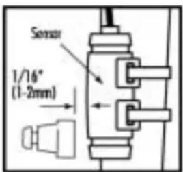
Position the sensor unit to the inside of either the right of left fork blade anywhere from 3-6 inches up from the fork blade tip. Attach the sensor to the fork blade with the quick ties but do not tighten the ties completely until final adjustment is complete.
-
Attach the wheel magnet to a spoke, aligning the magnet with the sensor so it faces and intersects the bottom polished line on the sensor. The magnet should have 1-2 mm clearance from the sensor. If the sensor and magnet are too close or touching, rotate the sensor unit toward the back of the fork blade until adequate clearance is achieved. Carefully tighten the quick ties making sure you maintain the proper space between the magnet and the sensor. Trim the excess quick tie strap using a scissors or fingernail clipper. Tighten the magnet screw, but be careful not to over tighten as this can damage the fitting.
Sensor Wiring and Bracket
natural_image
Technical line drawing of a bicycle suspension mechanism (no text or symbols)-
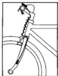
Route the sensor wire up the back of the fork blade or wind the wire around the blade, making sure that the wire is not loose and that you leave enough wire to reach the handlebar. Secure the wire to the fork blade immediately above the sensor and at the top of the fork blade, using the adhesive strips that are provided or electrical tape.
-
Wind the wire upward around the front brake cable until the wire is adjacent to the handlebar, allowing enough slack for free movement of the steering assembly cables.
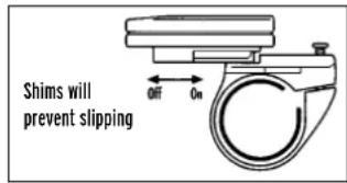
- Attach the bracket to the handlebar on either side of the stem. The bracket goes onto the handlebar with the wire toward the rider side of the bar. Use the appropriate rubber shim between the bracket and handlebar to provide a secure fit.
text_image
Shims will prevent slipping Off OnAttaching the Computer to the Bracket
The Trek Sensor Computer attaches to the mounting bracket by sliding the unit onto the bracket from the back until it snaps firmly into position. To remove the computer from the bracket, place your thumb against the back of the mounting bracket and pull the computer toward you with your index finger.
COMPUTER SET UP
Battery Installation
text_image
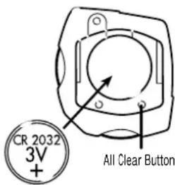
CR 2032 3V + All Clear Button- Remove the battery cover from the back side of the computer using a narrow flat blade screwdriver.
- Install the battery so that the positive "+" side of the battery is visible, and replace the battery cover.
CAUTION: On the bottom of the computer head next to the battery door is a small recessed button. This is the Auto Clear Button. Pressing this button will clear all memories and reset all functions to their default values.
BUTTON FUNCTIONS
text_image
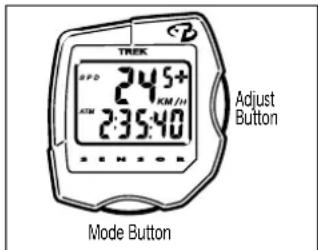
TREX 24.5+ 2:35:40 ADJUST Button Mode ButtonThe Sensor is equipped with 2 buttons that control the function of the unit.
1. MODE
Changes the Main Screens of the Sensor
2. ADJUST
Adjusts digits while programming and activates ATM lap timer.
PROGRAMMING YOUR TREK SENSOR CYCLE COMPUTER
Setting the Clock
- Press the mode key to advance to MXS/Clock display.
- Press and hold the mode key for over 2 seconds until hours setting begins to flash.
- Press the adjust key to adjust hours setting, press the mode key to confirm and advance to minutes setting.
- Press the adjust key (hold for fast advance) to adjust the minutes, and press the mode key to confirm setting and enter normal display mode.
Setting Miles/ Kilometers and Wheel Size
- Press mode computer key to enter AVS/ODO mode.
- Press and hold mode key for over 2 seconds until m/h begins to flash.
- Press adjust key to select miles (m/h) or kilometers (km/h) display.
- Press mode key to confirm choice and advance to wheel size setting.
- Adjust the flashing digit with the adjust button, confirm choice by pressing mode button, and advance to next flashing digit.
- Adjust and/or confirm all flashing digits.
Wheel Size Setting
The wheel size setting number is equal to the distance, in millimeters, that your front wheel travels during one complete revolution. Each time the wheel magnet passes the sensor unit on your fork, the sensor sends an impulse to the computer telling it that your wheel has completed one revolution. The computer calculates this distance vs. time to give you accurate readings for the various modes.
Determining Wheel Size Setting There are three methods for determining the wheel size setting. For the most accurate computer readings, it is best to measure the actual distance that your wheel travels in one complete revolution. This method is called a wheel roll out.
Method One: Wheel Roll Out
text_image
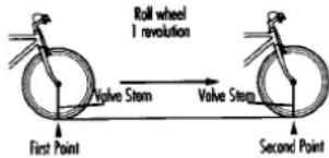
Roll wheel 1 revolution Valve Stem Valve Stem First Point Second Point- Perform the wheel roll out on a hard, flat, smooth surface such as a garage or basement floor.
-
Make sure your tires are properly inflated.
-
Position your bike so that the valve stem of the front wheel is at its bottom most position. Mark the spot on the floor directly under the center of the valve stem using a piece of tape or chalk.
-
Roll the bicycle forward in a straight line, while putting downward pressure on the handlebars to simulate rider weight. When the wheel has completed one revolution and the valve stem is at its bottom position, mark the floor directly under the center of the valve stem with tape or chalk. Measure the distance between the two marks in millimeters. (Note: Conversion of in. to mm. is 1 in.=25.4 mm.) This is your wheel setting number. You can repeat this procedure and average your results. We recommend that you record your wheel setting numbers here for future reference.
Method Two:
text_image
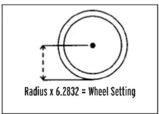
Radius x 6.2832 = Wheel SettingMeasure wheel radius (including tire) in mm and multiply by 6.2832=Wheel setting number.
Method Three:
Refer to the following chart and input the number that corresponds to your tire size. (Note: Actual size of two similarly marked tires from different manufactures can vary significantly, making this method the least accurate.)
WHEEL SIZE CHART
| Wheel/Tire Size in mm | Wheel Size Setting | |
| ATB | 26 x 1.0 ATB | .1913 |
| 26 x 1.25 | .1953 | |
| 26 x 1.5 | .1985 | |
| 26 x 1.9 | .2055 | |
| 26 x 2.0 | .2074 | |
| 26 x 2.1 | .2095 | |
| 26 x 2.2 | .2110 | |
| ROAD | 700 x 20c | .2074 |
| 700 x 23c | .2114 | |
| 700 x 25c | .2124 | |
| 700 x 28c | .2140 | |
| 700 x 32c | .2155 | |
| 700 x 35c | .2175 | |
| 700 x 38c | .2180 | |
| 700 x 40c | .2190 | |
| 650 x 20c | .1945 | |
| 650 x 23c | .1990 | |
| Wide 700c Tubular | .2117 | |
| Narrow 700c Tubular | .2105 | |
| 27 x 1" | .2145 | |
| 27 x 1-1/4 | .2160 | |
QUICK REFERENCE GUIDE
| Desired Function Which Key to Press Notes | ||
| Advance Digits While Programming Left Key Hold for Fast Advance | ||
| Set Digits While Programming Right Key | ||
| Set Clock Right for 2 Sec. In MXS/Clock Screen | ||
| Set Miles/Kilometers/Wheel Size Right for 2 Sec. In AVS/ODO Screen | ||
| Enter ATM “Lap Timer” Display Left for 2 Sec | In any Screen | |
| Reset ATM, DST, AVG and Max | Right for 2 Sec. | In SPD/ATM Screen |
TROUBLESHOOTING
- No Speed Reading Improper magnet to sensor alignment, computer improperly installed in bracket.
- Slow Display Response Temperature is outside operation limit (0°-55°C).
-
Display is Black Temperature is too hot. Remove from direct sunlight to return to proper operation.
-
Display Fades or Disappears Weak or dead battery, dirty battery contacts.
- Irregular Display Figures Check and record Total Odometer, then press Auto Clear button to initialize computer. Follow setup procedure and adjust Odometer setting.
RECORD DATA HERERECORD DATA HERE