
DH 40SR - Drill HITACHI - Free user manual and instructions
Find the device manual for free DH 40SR HITACHI in PDF.

| Type | Rotary Hammer Drill |
| Brand | Hitachi |
| Model | DH 40SR |
| Power Input | 950 W |
| Voltage | 110V-240V (depending on region) |
| No Load Speed | 510/min |
| Full-Load Impact Rate | 2800/min |
| Drill Bit Capacity | 40 mm |
| Core Bit Capacity | 120 mm |
| Weight (without cord) | 6.5 kg |
| Speed Control | Constant velocity regulator |
| Safety Clutch | Yes |
| Lubrication System | Grease lubrication (Hitachi Hammer Grease A) |
| Carbon Brushes | Auto-stop type, replaceable |
| Tool Retention | Hexagonal shank with push-button retainer |
| Side Handle | Included |
| Depth Stopper | Included |
| Standard Accessories | Case, side handle, stopper, hex wrenches, grease tube |
| Applications | Concrete drilling, anchor holes, chipping, crushing |
| Maintenance Interval | Grease replacement every 6 months |
| Safety Features | Earplug recommended, anti-kickback clutch |
Frequently Asked Questions - DH 40SR HITACHI
User questions about DH 40SR HITACHI
0 question about this device. Answer the ones you know or ask your own.
Ask a new question about this device
Download the instructions for your Drill in PDF format for free! Find your manual DH 40SR - HITACHI and take your electronic device back in hand. On this page are published all the documents necessary for the use of your device. DH 40SR by HITACHI.
USER MANUAL DH 40SR HITACHI
natural_image
Line drawing of a mechanical tool inside a circular frame (no text or symbols)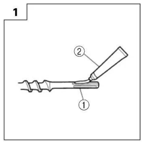
natural_image
Illustration of a hand using a tool to adjust or install a mechanical component (no text or symbols visible)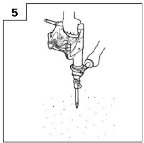
natural_image
Illustration of a hand using a power tool to apply material to a surface (no text or symbols)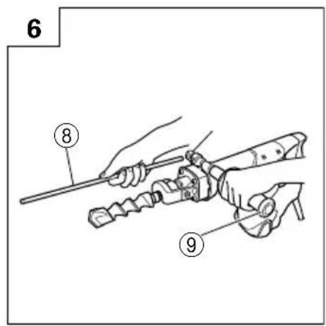
natural_image
Illustration of a hand using a tool to measure a mechanical component, with no visible text or symbols.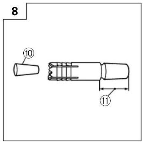
natural_image
Illustration of a hand using a tool to dig or press over soil (no text or symbols)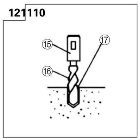
natural_image
Illustration of a hand holding a cylindrical tool and a clamp device (no text or symbols)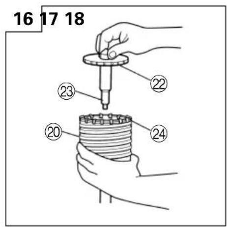
natural_image
Illustration of hands operating a mechanical tool with a threaded shaft (no text or symbols)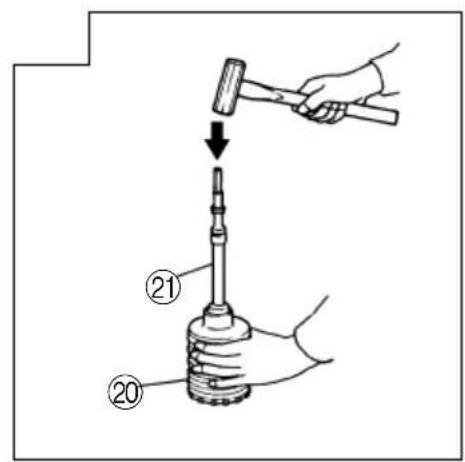
| 1 | 工具柄 | Tool shank |
| 2 | 润滑油 | Grease |
| 3 | 夹持器(钻具夹持器) | Retainer (tool holer) |
| 4 | 夹持器边缘 | Retainer edge |
| 5 | 按钮 | Push button |
| 6 | 前盖 | Front cover |
| 7 | 出口 | Outlet |
| 8 | 停止器 | Stopper |
| 9 | 侧柄 | Side handle |
| 10 | 塞子 | Plug |
| 11 | 打入自钻锚栓后,将此部分卸掉。 | Snap off this portion after driving in the self-drilling anchor. |
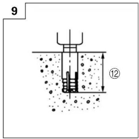
| 12 | 孔深 | Hole depth |
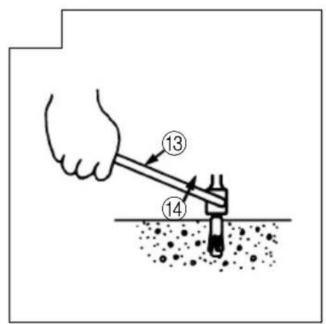
| 13 | 扳键 | Drift key |
| 14 | 扳出 | Wrench out |
| 15 | 锥柄附加器 | Taper shank adapter |
| 16 | 钻头(带锥柄) | Drill bit (taper shank) |
| 17 | 指示槽显示安装用于钻孔的描栓外径的标准深度。 | Indicating groove shows standard depth matching the outside diameter of the anchor for drilling. |
| 18 | 制销 | Cotter |
| 19 | 台座 | Rest |
| 20 | 取心钻具 | Core bit |
| 21 | 取心钻柄 | Core bit shank |
| 22 | 导板 | Guide plate |
| 23 | 中间销 | Center pin |
| 24 | 取心钻具尖端 | Core bit tip |
| 25 | 曲柄盖 | Crank cover |
| 26 | 磨损极限 | Wear limit |
| 27 | 碳刷号 | No. of Carbon Brush |
作业上的一般注意事项
W1/4 (No. 20), W5/16 (No. 25),
W3/8 (No. 30), W1/2 (No. 40),
W5/8 (No. 50)

(2) 扳键
○破碎(锤击)

(1) 尖凿
总长:280,450mm
○开槽和饰边(锤击)

(1) 冷钻
总长:280,450mm
○切柏油(锤击)
(1) 刀具
○喷射器(用于清除切层)
○电动锤润滑油 A
500g(在油罐内)
70g(在管内)
30g (在管内)
选购附件可能不预先通告而径予更改。
用途
○混凝土钻孔
○钻开锚栓孔
WARNING! When using electric tools, basic safety precautions should always be followed to reduce the risk of fire, electric shock and personal injury, including the following.
Read all these instructions before operating this product and save these instructions.
For safe operations:
- Keep work area clean. Cluttered areas and benches invite injuries.
- Consider work area environment. Do not expose power tools to rain. Do not use power tools in damp or wet locations. Keep work area well lit. Do not use power tools where there is risk to cause fire or explosion.
- Guard against electric shock. Avoid body contact with earthed or grounded surfaces (e.g. pipes, radiators, ranges, refrigerators).
- Keep children and infirm persons away. Do not let visitors touch the tool or extension cord. All visitors should be kept away from work area.
- Store idle tools. When not in use, tools should be stored in a dry, high or locked up place, out of reach of children and infirm persons.
- Do not force the tool. It will do the job better and safer at the rate for which it was intended.
- Use the right tool. Do not force small tools or attachments to do the job of a heavy duty tool. Do not use tools for purposes not intended; for example, do not use circular saw to cut tree limbs or logs.
- Dress properly. Do not wear loose clothing or jewelry, they can be caught in moving parts. Rubber gloves and non-skid footwear are recommended when working outdoors. Wear protecting hair covering to contain long hair.
- Use eye protection. Also use face or dust mask if the cutting operation is dusty.
- Connect dust extraction equipment. If devices are provided for the connection of dust extraction and collection facilities ensure these are connected and properly used.
- Do not abuse the cord. Never carry the tool by the cord or yank it to disconnect it from the receptacle. Keep the cord away from heat, oil and sharp edges.
- Secure work. Use clamps or a vise to hold the work. It is safer than using your hand and it frees both hands to operate tool.
- Do not overreach. Keep proper footing and balance at all times.
- Maintain tools with care. Keep cutting tools sharp and clean for better and safer performance. Follow instructions for lubrication and changing accessories. Inspect tool cords periodically and if damaged, have it repaired by authorized service center. Inspect extension cords periodically and replace, if damaged. Keep handles dry, clean, and free from oil and grease.
- Disconnect tools. When not in use, before servicing, and when changing accessories such as blades, bits and cutters.
-
Remove adjusting keys and wrenches. Form the habit of checking to see that keys and adjusting wrenches are removed from the tool before turning it on.
-
Avoid unintentional starting. Do not carry a plugged-in tool with a finger on the switch. Ensure switch is off when plugging in.
- Use outdoor extension leads. When tool is used outdoors, use only extension cords intended for outdoor use.
- Stay alert. Watch what you are doing. Use common sense. Do not operate tool when you are tired.
- Check damaged parts. Before further use of the tool, a guard or other part that is damaged should be carefully checked to determine that it will operate properly and perform its intended function. Check for alignment of moving parts, free running of moving parts, breakage of parts, mounting and any other conditions that may affect its operation. A guard or other part that is damaged should be properly repaired or replaced by an authorized service center unless otherwise indicated in this handling instructions. Have defective switches replaced by an authorized service center. Do not use the tool if the switch does not turn it on and off.
- Warning The use of any accessory or attachment, other than those recommended in this handling instructions, may present a risk of personal injury.
- Have your tool repaired by a qualified person. This electric tool is in accordance with the relevant safety requirements. Repairs should only be carried out by qualified persons using original spare parts. Otherwise this may result in considerable danger to the user.
PRECAUTIONS ON USING ROTARY HAMMER
○Wear earplugs to protect your ears during operation.
○Do not touch the bit during or immediately after operation. The bit becomes very hot during operation and could cause serious burns.
Before starting to break, chip or drill into a wall, floor or ceiling, thoroughly confirm that such items as electric cables or conduits are not buried inside.
○Always hold the body handle and side handle of the power tool firmly. Otherwise the counterforce produced may result in inaccurate and even dangerous operation.
SPECIFICATIONS
| Voltage (by areas)*1 | (110V, 115V, 120V, 127V, 220V, 230V, 240V) |
| Power input 950 W* | 1 |
| Capacity Drill bit: 40 mm | Core bit: 120 mm |
| No load speed*2 | 510/min |
| Full-load impact rate*2 | 2800/min |
| Weight (without cord, side handle) 6.5 kg |
*1 Be sure to check the nameplate on product as it is subject to change by areas.
*2 With constant velocity regulator.
STANDARD ACCESSORIES
(1) Case (Molded plastic) 1
(2) Side Handle 1
(3) Stopper 1
(4) Hexagon Bar Wrench (for 6 mm screw) .... 1
(5) Hexagon Bar Wrench (for 5 mm screw) .... 1
(6) Hexagon Bar Wrench (for 4 mm screw) ...... 1
(7) Hammer Grease A 1
Standard accessories are subject to change without notice.
OPTIONAL ACCESSORIES (sold separately)
○Through-hole drilling (Rotation + Hammering)

(1) Drill bit (hexagon shank) Overall length: 280, 400, 505 mm External dia.: 16, 19, 22, 25, 28, 32, 38 mm
○Anchor hole drilling (Rotation + Hammering)

(3) Cotter
natural_image
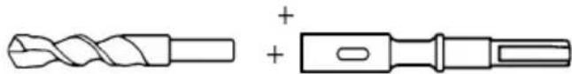
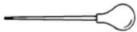
Technical line drawing of a twist drill bit and a rectangular tool (no text or symbols)(1) Drill bit (taper shank) External dia.: 11, 12, 14.3, 14.5, 17.5, 21.5 mm
(2) Taper shank adapter
| Taper shank adapter | Application drill bit |
| Morse taper (No. 1) | Drill bit (taper shank)11, 12, 14.3, 14.5, 17.5 mm |
| Morse taper (No. 2) | Drill bit (tape shank)21.5 mm |
| A-taper | Taper shank adapter formed A-taper or B-taper is provided as optional accessory, but drill bit for it is not provided. |
| B-taper |
○Large dia. hole boring (Rotation + Hammering)
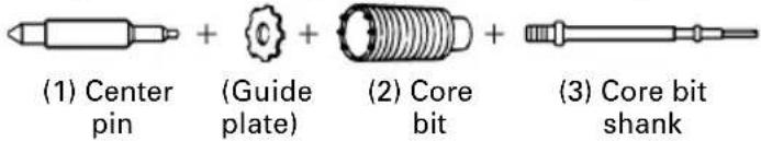
(1) Center pin
●Applied to core bits from 38 mm to 105 mm
●Applied to core bits 32 mm and 35 mm
NOTE:
Do not use core bits 25 mm or 29 mm.
(2) Core bit
●External dia. 25, 29, 32, 35, 38, 45, 54, 64, 79, 94, 105 mm
(with guide plate, not applicable to cores 25 mm or 29 mm)
(3) Core bit shank
●Applied to core bits above 38 mm
●Applied to core bits below 35 mm
●Anchor work (for self-anchors)
(1) Anchor adapter (for Rotation + Hammering) Anchor size: W1/4, W5/16, W3/8, W1/2, W5/8 (No. 20) (No. 25) (No. 30) (No. 40) (No. 50)
(2) Drift key
○Crusing (Hammering)

(1) Bull point Overall length: 280, 450 mm
○Groove digging and edging (Hammering)

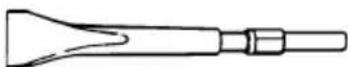
(1) Cold chisel Overall length: 280, 450 mm
○Asphalt cutting (Hammering)

(1) Cutter
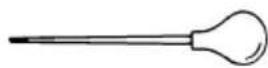
○Syringe (for chip removal)
○Hammer grease A
500 g (in a can)
70 g (in a green tube)
30 g (in a green tube)
Optional accessories are subject to change without notice.
APPLICATIONS
○Drilling holes in concrete
○Drilling anchor holes
○Crushing concrete, chipping, digging, and squaring (by applying optional accessories)
PRIOR TO OPERATION
1. Power source
Ensure that the power source to be utilized conforms to the power requirements specified on the product nameplate.
2. Power switch
Ensure that the power switch is in the OFF position. If the plug is connected to a power receptacle while the power switch is in the ON position, the power tool will start operating immediately, which could cause a serious accident.
3. Extension cord
When the work area is removed from the power source, use an extension cord of sufficient thickness and rated capacity. The extension cord should be kept as short as practicable.
4. How to install tool
NOTE:
For tools such as a bull point and a cold chisel, use only Hitachi genuine parts.
(1) Clean, then smear the tool shank with the grease provided in the green tube. (Fig. 1)
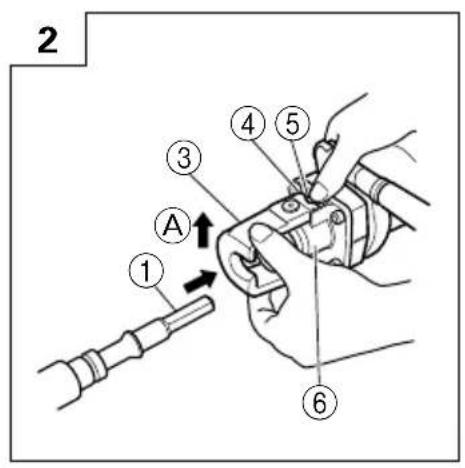
(2) Press the push button, slightly lift the tool retainer in the direction of arrow Ⓐ as shown in Fig. 2 to hook the tool retainer edge with the push button and engage the push button.
(3) Release your finger from the push button and further lift the tool retainer in the direction of arrow Ⓐ.
NOTE:
First time when the tool retainer is lifted, remove your finger from the push button. If the push button is kept pressed, the edge of the tool retainer comes in contact with your finger and the tool retainer cannot be lifted.
(4) Fully insert the tool shank into the hexagonal hole in the front cover.
(5) Return the tool retainer to secure the tool.
(6) Pull the tool to make sure it is locked completely.
NOTE:
Remove in the reverse order of installation.
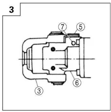
WHEN THE PUSH BUTTON DOES NOT OPERATE SMOOTHLY
When the push button does not operate smoothly, please remove dirt from the inside through the outlet using a
wire, etc. Then lubricate lubricating oil and push the push button several times to make it operate smoothly. (Fig. 3)
HOW TO USE THE ROTARY HAMMER
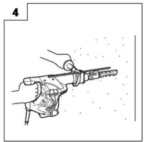
1. How to drill holes (Fig. 4)
(1) Pull the switch trigger after applying the drill bit tip to the drilling position.
(2) It is unnecessary to forcibly press the rotary hammer main body. It is sufficient to slightly press the rotary hammer to an extent that shavings are freely discharged.
CAUTION:
Although this machine is equipped with a safety clutch, if the drill bit becomes bound in concrete or other material, the resultant stoppage of the drill bit could cause the machine body to turn in reaction. Ensure that the main handle and side handle are gripped firmly during operation.
2. How to chisel or crush (Fig. 5)
By applying the drill bit tip to the chiseling or crushing position, operate the rotary hammer by utilizing its empty weight.
Forcible pressing or thrusting is unnecessary.
3. Install the stopper (Fig. 6)
(1) Loosen the side handle and insert the straight portion of the stopper into the handle bolt hole.
(2) Move the stopper to the specified position and rotate the grip of the side handle clockwise to fix the stopper.
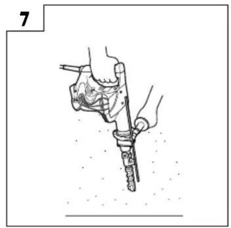
4. Warming up (Fig. 7)
The grease lubrication system in this unit may require warming up in cold regions.
Position the end of the bit so makes contact with the concrete, turn on the switch and perform the warming up operation. Make sure that a hitting sound is produced and then use the unit.
CAUTION:
When the warming up operation is performed, hold the side handle and the main body securely with both hands to maintain a secure grip and be careful not to twist your body by the jammed drill bit.
DRILLING AND DRIVING-IN OPERATIONS FOR ANCHORS
Use the optional accessories for anchors, such as anchor adapter and taper shank adapter.
1. When a rotation hammering anchor adapter is used.
(1) Install the self-drilling anchor in the anchor adapter. (Fig. 8)
(2) Turn ON the switch and drill a base hole with the self-drilling anchor. (Fig. 9)
At the start of the hole-drilling slightly tilt the rotary hammer to determine the hole position.
(3) After cleaning out dust with a syringe, attach the plug to the anchor tip and drive in the anchor with a manual hammer.
(4) After driving in the anchor, use the drift key to separate the anchor. (Fig. 10)
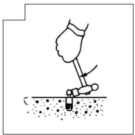
(5) By employing a manual hammer or pliers, snap off the tapered portion of the anchor. (Fig. 11)
CAUTION:
Since the snapped-off tapered portion will fly about, pay attention to the snapping direction.
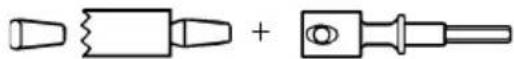
2. When a taper shank adapter is used (Fig. 12)
(1) Install drill bit with taper shank in the taper shank adapter.
(2) Turn the power on and drill a base hole to the depth sounded by indicating groove on the drill bit.
(3) After cleaning out dust with a syringe, attach the plug to the anchor tip and drive in the anchor with a manual hammer.
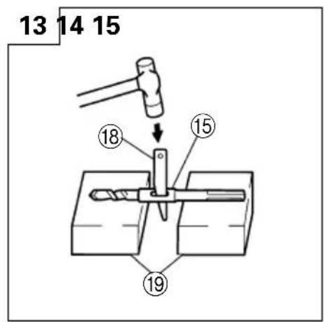
(4) To remove the drill bit (taper shank), insert the cotter into the slot of the taper shank adapter and strike the head of the cotter with a manual hammer supporting on a rest. (Fig. 13)
HOW TO HANDLE A CORE BIT
When a core bit is used, large diameter holes and blind holes can be drilled. In this case, use optional accessories for core bits (such as a center pin and core bit shank) for more efficient operation.
1. Mounting
CAUTION:
Prior to mounting a core bit, always disconnect the plug from the power supply receptacle.
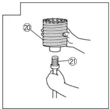
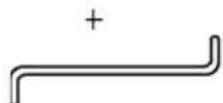
(1) Mount the core bit on the core bit shank. (Fig. 14) Before that, feed oil to the screw portion of core bit shank for easy dismounting.
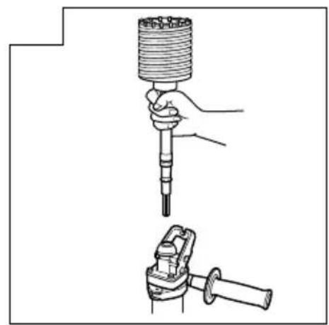
(2) Mount the core bit shank on the main body in the same manner as in mounting the drill bit and the bull point. (Fig. 15)
(3) Insert the center pin into the guide plate until it reaches the extremity.
(4) Fit in the guide plate by aligning its concaved portion with the core bit tip. When the position of the concave is shifted by turning the guide plate right or left, the guide plate never slips off even when the drill is used in a downward direction. (Fig. 16)
2. Drilling holes
(1) Insert the plug into a receptacle.
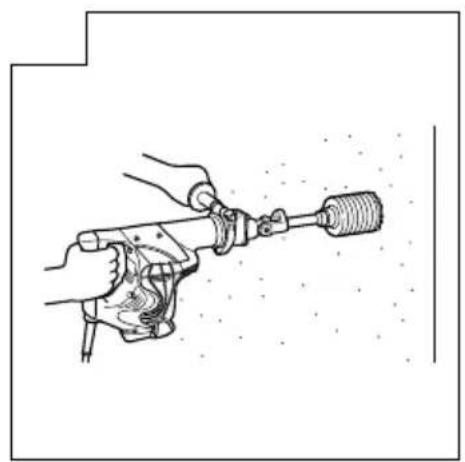
(2) A spring is built in the center pin. By straightly and gently pressing it to the wall or floor surface, the entire surface of the core bit tip attains contact to start the hole drilling job. (Fig. 17)
(3) When the hole depth reaches approximately 5 mm, the hole position can be determined. Then remove the center pin and guide plate from the core bit and continue the hole drilling job.
When removing the center pin and guide plate, always disconnect the plug from the receptacle.
CAUTION:
3. How to dismount the core bit
Remove the core bit shank from the rotary hammer, hold the core bit with one hand, and strongly strike the head of the hexagonal portion of the core bit shank with a manual hammer two or three times, whereby the round head screw is loosened and the rotary hammer is ready for disassembly. (Fig. 18)
HOW TO REPLACE GREASE
This machine is of full air-tight construction to protect against dust and to prevent lubricant leakage. Therefore, the machine can be used without lubrication for long periods. Replace the grease as described below.
1. Grease replacement period
After purchase, replace grease after every 6 months of usage. Ask for grease replacement at the nearest Hitachi authorized Service center. Proceed for replacement of grease.
2. Grease replenishment
CAUTION:
Before replenishing the grease, turn the power off and pull out the power plug.
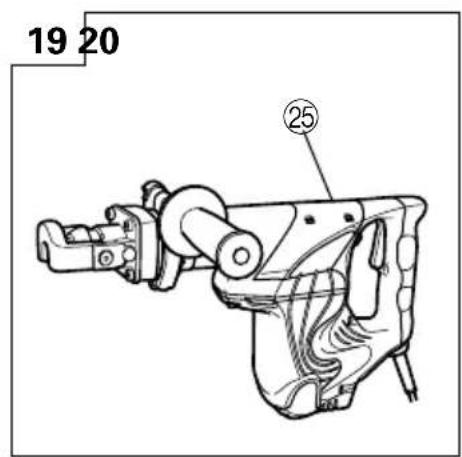
(1) Remove the crank cover and wipe off the grease inside. (Fig. 19)
(2) Supply 30g of Hitachi Electric Hammer Grease A (Standard accessory, contained in tube) to the crank case.
(3) After replenishing the grease, install the crank cover securely.
NOTE:
The Hitachi Electric Hammer Grease A is of the low viscosity type. If necessary purchase from an Hitachi authorized Service center.
MAINTENANCE AND INSPECTION
1. Inspecting the tool
Since use of a dull tool will degrade efficiency and cause possible motor malfunction, sharpen or replace the tool as soon as abrasion is noted.
2. Inspecting the mounting screws
Regularly inspect all mounting screws and ensure that they are properly tightened. Should any of the screws be loose, retighten them immediately. Failure to do so could result in serious hazard.
3. Maintenance of the motor
The motor unit winding is the very "heart" of the power tool. Exercise due care to ensure the winding does not become damaged and/or wet with oil or water.
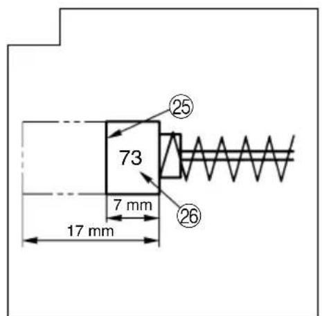
4. Inspecting the carbon brushes (Fig. 20)
The Motor employs carbon brushes which are consumable parts. When they become worn to or near the "wear limit", it could result in motor trouble. When an auto-stop carbon brush is equipped, the motor will stop automatically. At that time, replace both carbon brushes with new ones which have the same carbon brush Numbers shown in the figure. In addition, always keep carbon brushes clean and ensure that they slide freely within the brush holders.
5. Replacing carbon brushes
Loosen the two set screws and remove the tail cover. Remove the brush caps and carbon brushes. After replacing the carbon brushes, tighten the brush caps securely and install the tail cover with securely tightening two set screws.
6. Service parts list
A: Item No.
B: Code No.
C: No. Used
D: Remarks
CAUTION:
Repair, modification and inspection of Hitachi Power Tools must be carried out by an Hitachi Authorized Service Center.
This Parts List will be helpful if presented with the tool to the Hitachi Authorized Service Center when requesting repair or other maintenance.
In the operation and maintenance of power tools, the safety regulations and standards prescribed in each country must be observed.
MODIFICATIONS:
Hitachi Power Tools are constantly being improved and modified to incorporate the latest technological advancements.
Accordingly, some parts (i.e. code numbers and/or design) may be changed without prior notice.
NOTE:
Due HITACHI's continuing program of research and development, the specifications herein are subject to change without prior notice.
natural_image
Line drawing of a quill pen with inkwell, no text or symbols present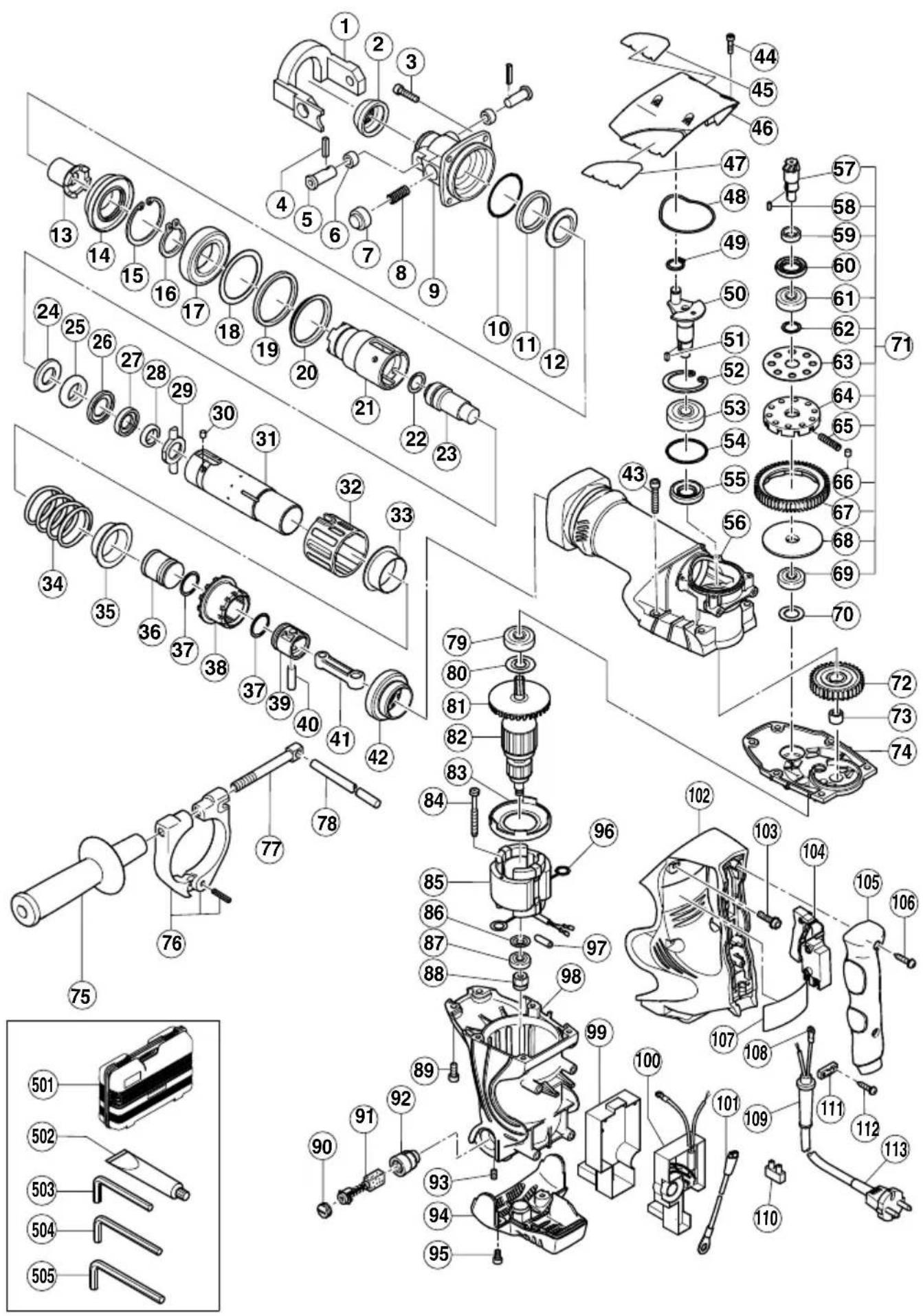
| A | B | C | D |
| 1 990-131 1 | |||
| 2 ———— 1 | |||
| 3 981-942 4 M6 × 25 | |||
| 4 991-697 2 | |||
| 5 990-135 2 | |||
| 6 990-134 2 | |||
| 7 990-133 1 | |||
| 8 990-132 1 | |||
| 9 321-844 1 | |||
| 10 956-996 1 1AS-60 | |||
| 11 321-843 1 | |||
| 12 321-842 1 | |||
| 13 321-841 1 | |||
| 14 321-840 1 | |||
| 15 321-839 1 | |||
| 16 948-131 1 | |||
| 17 600-7DD 1 6007DDUAV2S | |||
| 18 321-297 1 | |||
| 19 981-859 1 | |||
| 20 321-838 1 | |||
| 21 321-837 1 | |||
| 22 313-396 1 | |||
| 23 321-833 1 | |||
| 24 321-836 1 | |||
| 25 321-835 1 | |||
| 26 321-834 1 | |||
| 27 321-856 1 | |||
| 28 321-832 1 | |||
| 29 321-831 1 | |||
| 30 313-057 4 D6 × 6 | |||
| 31 321-827 1 | |||
| 32 321-830 1 | |||
| 33 321-829 1 | |||
| 34 321-828 1 | |||
| 35 321-977 1 | |||
| 36 321-976 1 | |||
| 37 986-104 2 | |||
| 38 321-975 1 | |||
| 39 321-284 1 | |||
| 40 980-708 1 | |||
| 41 321-285 1 | |||
| 42 321-296 1 | |||
| 43 986-940 4 M6 × 45 | |||
| 44 983-162 4 M4 × 12 | |||
| 45 ———— 1 | |||
| 46 321-315 1 | |||
| 47 ———— 1 | |||
| 48 321-314 1 | |||
| 49 939-540 1 | |||
| 50 321-275 1 | |||
| 51 ———— 1 | |||
| 52 948-391 1 | |||
| 53 620-3DD 1 6203DDCMPS2L | |||
| 54 996-363 1 S-40 | |||
| 55 321-274 1 | |||
| 56 321-826 1 | |||
| 57 321-278 1 | |||
| 58 ———— 1 | |||
| 59 321-279 1 | |||
| 60 313-050 1 | |||
| 61 600-2DD 1 6002DDCMPS2L | |||
| 62 313-058 1 | |||
| 63 313-053 1 | |||
| 64 321-281 1 |

Hitachi Koki Co., Ltd.
- 作业上的一般注意事项
- 用途
- PRECAUTIONS ON USING ROTARY HAMMER
- SPECIFICATIONS
- STANDARD ACCESSORIES
- OPTIONAL ACCESSORIES (sold separately)
- APPLICATIONS
- PRIOR TO OPERATION
- Power source
- Power switch
- Extension cord
- How to install tool
- NOTE:
- WHEN THE PUSH BUTTON DOES NOT OPERATE SMOOTHLY
- HOW TO USE THE ROTARY HAMMER
- How to drill holes (Fig. 4)
- CAUTION:
- How to chisel or crush (Fig. 5)
- Install the stopper (Fig. 6)
- Warming up (Fig. 7)
- DRILLING AND DRIVING-IN OPERATIONS FOR ANCHORS
- When a rotation hammering anchor adapter is used.
- When a taper shank adapter is used (Fig. 12)
- HOW TO HANDLE A CORE BIT
- Mounting
- Drilling holes
- How to dismount the core bit
- HOW TO REPLACE GREASE
- Grease replacement period
- Grease replenishment
- MAINTENANCE AND INSPECTION
- Inspecting the tool
- Inspecting the mounting screws
- Maintenance of the motor
- Inspecting the carbon brushes (Fig. 20)
- Replacing carbon brushes
- Service parts list
- MODIFICATIONS:
- Hitachi Koki Co., Ltd.
Brand : HITACHI
Model : DH 40SR
Category : Drill