EFG 425KS - Forklift Jungheinrich - Free user manual and instructions
Find the device manual for free EFG 425KS Jungheinrich in PDF.


User questions about EFG 425KS Jungheinrich
0 question about this device. Answer the ones you know or ask your own.
Ask a new question about this device
Download the instructions for your Forklift in PDF format for free! Find your manual EFG 425KS - Jungheinrich and take your electronic device back in hand. On this page are published all the documents necessary for the use of your device. EFG 425KS by Jungheinrich.
USER MANUAL EFG 425KS Jungheinrich
Operating Instructions
GB
52020422
07.08
natural_image
Line drawing of a forklift carrying a vehicle, showing front wheel, side lift, and gear (no text or symbols)Foreword
The present ORIGINAL OPERATING INSTRUCTIONS are designed to provide sufficient instruction for the safe operation of the industrial truck. The information is provided clearly and concisely. The chapters are arranged by letter. Each chapter starts with page 1. The page identification consists of a chapter letter and a page number.
For example: Page B 2 is the second page in chapter B.
The operating instructions detail different truck models. When operating and servicing the truck, make sure that the instructions apply to your truck model.
Safety instructions and important explanations are indicated by the following graphics:

Used before safety instructions which must be observed to avoid danger to personnel.

Used before notices which must be observed to avoid material damage.

Used before notices and explanations.
●Used to indicate standard equipment.
○Used to indicate optional equipment.
Our trucks are subject to ongoing development. Jungheinrich reserves the right to alter the design, equipment and technical features of the truck. No guarantee of particular features of the truck should therefore be inferred from the present operating instructions.
Copyright
Copyright of these operating instructions remains with JUNGHEINRICH AG.
1 Design and application ...... B 1
2 Description of assembly groups and functions ...... B 2
2.1 Truck B 3
3 Technical data - standard version ...... B 4
3.1 Performance data ...... B 7
3.2 Weight (all weights in kg) B 8
3.3 Tyres B 8
3.4 EN standards B 9
3.5 Conditions for application ...... B 9
4 Label positions and identification plates ...... B 10
4.1 Identification plate, truck B 12
4.2 Truck load diagram B 12
4.3 Fork arm load diagram (basic device) B 13
4.4 Attachment load diagram B 13
C T r a n s p o r t a t i o n a
1 Transportation by crane C 1
2 Securing the truck during transport C 2
3 Commissioning C 3
4 Moving the truck with the drive unit inoperative C 4
5 Steering the truck without its own drive system (o) ...... C 5
6 Towing the truck C 5
D B a t t e r y - S e r v i c
1 Safety regulations governing the handling of lead-acid batteries ..... D 1
2 Battery types ...... D 2
3 Opening the battery hood with support system (o) ...... D 3
4 Exposing the battery ....D 4
5 Charging the battery ....D 5
5.1 Charger socket (○) D 6
6 Removing and installing the battery ..... D 7
7 Closing battery cover D 8
8 Battery discharge indicator, exhaustive discharge protection device, operating hour meter ....D 8
E O p e r a t i o n
1 Safety Regulations for the Operation of Forklift Trucks ...... E 1
2 Controls and Displays E 2
2.1 Instrument panel switches ...... E 6
2.2 Control panel switches E 6
2.3 Multi-function display E7
2.4 Control panel (o) E 9
2.5 Setting the time E 14
2.6 Warning registration on driver's display E 15
3 Starting up the truck E 16
3.1 Checks and operations to be performed before starting daily work .... E 16
3.2 Trucks with reduced headroom X (o) E 16
3.3 Adjusting the driver's seat E 17
3.4 Safety restraint belt E 18
3.5 Safety Restraint System (o) E 20
3.6 Adjusting the steering column E 22
3.7 Preparing the truck for operation E 22
3.8 Trucks with Heating (o) E 23
4 Industrial Truck Operation E 24
4.1 Safety regulations for truck operation ...... E 24
4.2 Travel E 26
4.3 Steering E 29
4.4 Braking E 29
4.5 Operating the lift mechanism and attachments (MULTI-PILOT) ..... E 31
4.6 Operating the lift mechanism and attachments (SOLO-PILOT) ...... E 33
4.7 Operating the lift mechanism and attachments (multifunction steering wheel) E 35
4.8 Collecting, transporting and depositing loads E 36
4.9 Parking the truck securely E 39
4.10 Towing trailers E 40
4.11 Tow loads E 40
5 Troubleshooting E 41
F M a i n t e n a n c e o f
1 Operational safety and environmental protection ...... F 1
2 Safety regulations applicable to truck maintenance ...... F 1
3 Servicing and inspection ...... F 3
4 Maintenance checklist EFG ...... F 4
5 Lubrication Schedule ...... F 6
5.1 Fuels, coolants and lubricants ...... F 7
6 Description of servicing and maintenance operations ...... F 8
6.1 Prepare truck for the servicing and maintenance operations ...... F 8
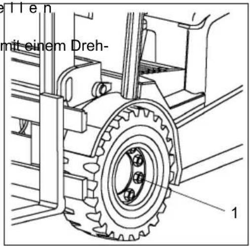
6.2 Check attachment of tyres ...... F 8
6.3 Tyre pressure ...... F 8
6.4 Check hydraulic oil level ...... F 9
6.5 Check transmission oil level F 10
6.6 Draining oil F 10
6.7 Refilling oil F 10
6.8 Changing the hydraulic filter ...... F 10
6.9 Changing the vacuum filter ...... F 11
6.10 Check oil level for brake system ...... F 11
6.11 Restrain safety belt service ...... F 12
6.12 Checking the electric fuses ...... F 13
6.13 Recommissioning after cleaning or maintenance operations ...... F 15
7 Decommissioning the fork lift truck ...... F 15
7.1 Operations to be performed prior to decommissioning ...... F 15
7.2 Measures to be taken during decommissioning ...... F 15
7.3 Recommissioning the truck ...... F 16
8 Safety tests to be performed at intervals and after unusual events .... F 16
9 Final de-commissioning, disposal ...... F 16
Appendix
JH Traction Battery Operating Instructions

These operating instructions apply only to Jungheinrich battery models. If using another brand, refer to the manufacturer's operating instructions.
A Correct use and

The „Guidelines for the Correct Use and Application of Industrial Trucks“ (VDMA) are included in the scope of delivery for this truck. The guidelines are part of these operating instructions and must always be heeded. National regulations are fully applicable.
The fork-lift truck described in these operating instructions is a truck that is suitable for lifting and transporting loads.
It must be used, operated and maintained according to the information in these operating instructions. Any other uses are outside the design envelope and can lead to injury to persons or damage to equipment and property. Above all, overloading caused by excessively heavy or unbalanced loads must be avoided. The max. admissible load to be picked up is indicated on the identification plate or load diagram label shown on the truck. The operator must ensure that damaged and/or poorly readable load diagrams are renewed. The fork-lift truck must not be operated in spaces subject to fire or explosion hazards, or in spaces where corrosive or very dusty atmospheres prevail.
Duties of the user: A „user“ within the meaning of these operating instructions is defined as any natural or legal person who either uses the fork-lift truck himself, or on whose behalf it is used. In special cases (e.g. leasing or renting), the user is considered the person, who, in accordance with existing contractual agreements between the owner and the user of the fork-lift truck, is charged with the observance of the operating duties.
The user must ensure that the truck is not abused and only used within its design limits and that all danger to life and limb of the operator, or third parties, is avoided. In addition to this, it must be ensured that the relevant accident prevention regulations and other safety-related provisions, as well as the operating, servicing and maintenance guidelines, are observed. The user must also ensure that all persons operating the truck have read and understood these operating instructions.

If these operating instructions are not observed the warranty becomes void. The same applies if improper works are carried out at the device by the customer and/or third parties without permission of our Customer Service.
Mounting of attachments: The mounting or installation of any attachments which will interfere with, or supplement, the functions of the truck is permitted only after written approval by the manufacturer has been obtained. If necessary, the approval of local authorities has to be obtained.
Any approval obtained from local authorities does not, however, make the approval by the manufacturer unnecessary.
Trailing and slipping loads: The truck may only be used for trailing or slipping loads for which the truck has been approved.
B Description of tr
1 D e s i g n a n d a p p
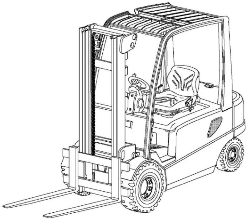
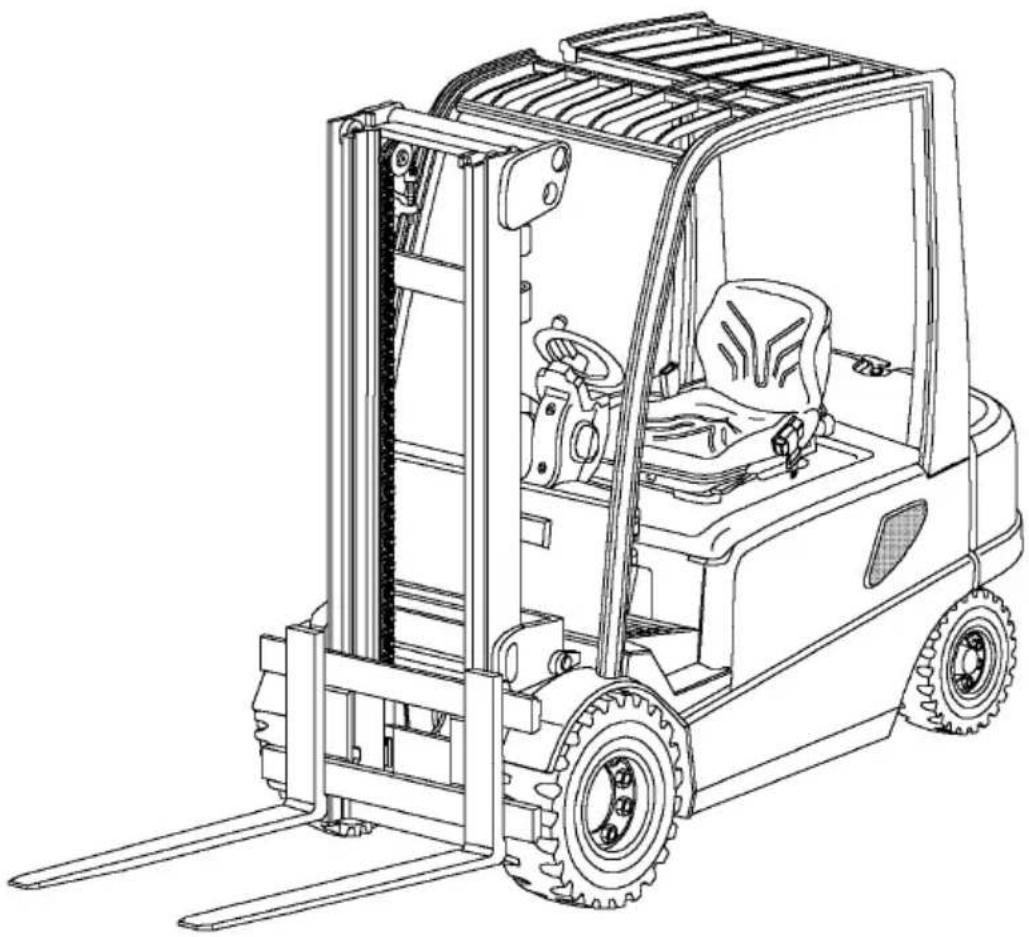
EFG 422-430 is an electric rider-controlled fork lift truck in four-wheel construction with front drive which picks up, transports, and lifts its load outside the wheelbase. It is a cantilevered counterbalance truck which can – due to its load lifting device being located in front of the lift truck – unload lorries and deliver the load on ramps or in racks unimpededly. It can be used to stack and transport DIN 15142 pallets, DIN 15144 lattice box pallet, and other palletised loads.
Truck types and maximum carrying capacity:
| Type max. carrying capacity *) Load centre | |
| EFG 422 2,200 kg 500 mm | |
| EFG 425 2,500 kg 500 mm | |
| EFG 430 3,000 kg 500 mm |
*) The load diagrams attached to the trucks are binding for the carrying capacity
natural_image
Line drawing of a forklift carrying a vehicle, showing front wheel, side lift, and gear (no text or symbols)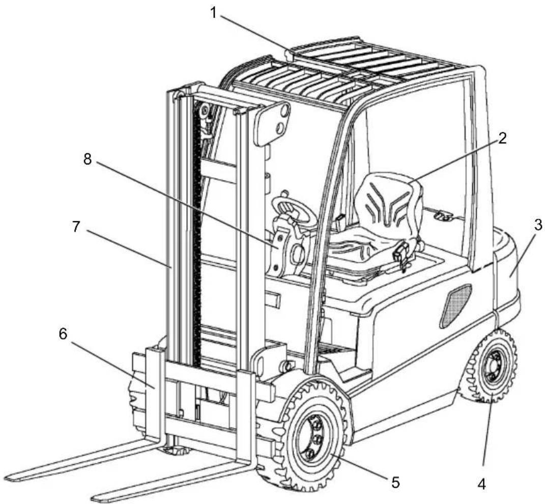
text_image
Technical diagram of a forklift with numbered parts labeled for identification| Item Designation | |
| 1 | Overhead guard |
| 2 | Driver seat |
| 3 | Counterweight |
| 4 | Steering axle |
| 5 | Drive axle |
| 6 | Fork arm carriage |
| 7 | Lifting mast |
| 8 | Steering |
2.1 Truck
Steering (8): When a load is applied to the driver seat the steering is switched to Standby. The steering unit runs at a preset idle speed. Depending on the steering request the steering pump is increased and the travel speed is reduced depending on the steering arc (“CurveControl”). The steering angle is indicated in the display.
Driver seat (2): The driver seat is a comfort seat and the steering column is adjustable. There are storage places for documents or personal belongings of the driver. The MULTI-PILOT combines all hydraulic functions and the travel direction switch in one single lever. The overhead guard (1) is prepared for a cabin installation and thus can be easily retrofitted.
Electric/electronic system: Sophisticated three-phase AC technology enables data transfers with few cables only (CAN bus). Thus we achieve decreased susceptibility to faults caused be broken cables as well as considerably faster fault isolation. The complex TC system (Total Control) is designed for simply, safe, and flexible usage. Depending on the load the driver can select from different operating programmes: from high-performance to energy-saving. Convenient and very fast fault analysis and programming can be performed via PC.
Drive and brake system: The front drive offers ideal traction to the drive wheels at all times.
The hydraulically actuated oil-bath multi-disk brake used a service brake is practically maintenance-free. The encapsulation in the transmission allows applications even in aggressive environments. In addition, the lift truck is generatively braked via the travel motor. Thus the energy consumption is minimised.
After approximately 15 sec standstill of the truck or 1 to 15 sec (adjustable) after the driver seat is relieved the spring-loaded brake engages.
When actuating the accelerator the spring-loaded brake is automatically disengaged.
Hydraulic system: All functions must be executed sensitively, proportionally, and simultaneously (only if this does not impair the safety). For higher efficiency a hydraulic unit and a steering booster motor function separately from each other. The micro pressure filter can be changed from the top (without spilling hydraulic oil).
Lifting mast (7): Our goal is optimising the view. The high-strength steel profiles are narrow, which is especially notable in the three-stage lifting mast with its good view to the fork arms. The same good results are achieved for the fork arm carriage.
The lifting mast as well as the fork arm carriage move on prelubricated and thus maintenance-free cocked support rollers.

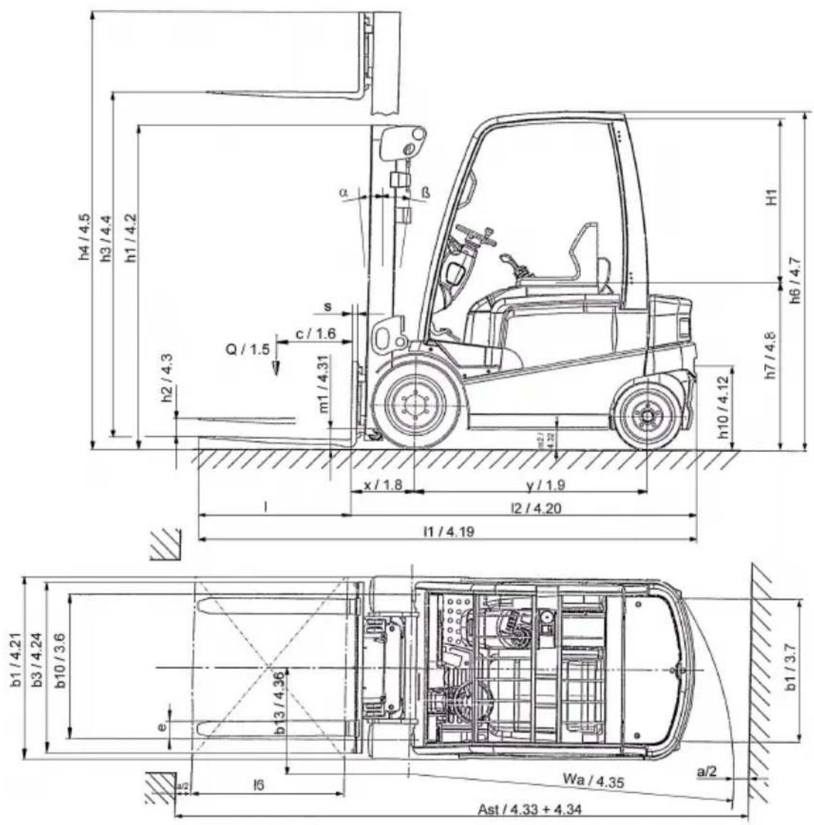
Technical specification details in accordance with VDI 2198. Technical modifications and additions reserved.
| Designation | EFG422 | EFG425k | EFG425 | ||
| h_1 | Height with mast retracted 2,200 2,200 2,200 mm | ||||
| h_2 | Free lift height 150 150 150 mm | ||||
| h_3 | Lift 3,100 3,100 3,100 mm | ||||
| h_4 | Height with mast extended 3,696 3,696 3,696 mm | ||||
| h_6 | Height above overhead guard 2,215 2,215 2215 mm | ||||
| h_7 | Seating height/standing height 1,060 1,060 1,060 mm | ||||
| Seating room H1 1,105 1,105 1,105 | |||||
| h_10 | Coupling height | 390/550 | 390/550 | 390/550 | mm |
| L_1 | Overall length including fork 3,428 3,428 3,572 mm | ||||
| L_2 | Length including fork back 2,278 2,278 2,422 mm | ||||
| b1 | Overall width | 1,196 | 1,196 | 1,196 mm | |
| b3 | Width of fork arm carriage | 1,120 | 1,120 | 1,120 | mm |
| m_1 | Ground clearance with load under lifting mast | 110 | 110 | 110 | mm |
| m_2 | Ground clearance at centre of wheelbase | 125 | 125 | mm | |
| Ast | Width of aislewith pallets 800 × 1,200 lengthwise | 3,875 | 3,875 | 4,025 mm | |
| Ast | Width of aislewith pallets 1,000 × 1,200 crossways | 3,675 | 3,675 | 3,825 mm | |
| W_a | Turning radius | 2,050 | 2,050 | 2,200 mm | |
| x | Load distance | 425 ^1) | 425 ^1) | 425 ^1) | mm |
| y | Wheel-base | 1,537 | 1,537 | 1,681 | mm |
1) = +25 mm DZ mast
| Designation | EFG425ks | EFG425s | EFG430 | ||
| h_1 | Height with mast retracted 2,200 2,200 2 | 200 mm | |||
| h_2 | Free lift height 150 150 150 mm | ||||
| h_3 | Lift 3,100 3,100 3,100 mm | ||||
| h_4 | Height with lifting mast extended 3,696 3 | 696 3,806 mm | |||
| h_6 | Height above overhead guard 2,215 2,215 | 2,215 mm | |||
| h_7 | Seating height/standing height 1,060 1,060 | 1,060 mm | |||
| Seat clearanceH1 1,105 1,105 1,105 | |||||
| h_10 | Coupling height 390/550 390/550 390/550 | mm | |||
| L_1 | Overall length including fork 3,428 3,572 | 3,577 mm | |||
| L_2 | Overall length including fork back 2,278 | 2,422 2,427 mm | |||
| b1 | Overall width | 1,196 1 | 1,196 1,196 mm | ||
| b3 | Width of fork arm carriage | 1,120 | 1,120 | 1,120 | mm |
| m_1 | Ground clearance under lifting mastwith load | 110 1 | 10 110 mm | ||
| m_2 | Ground clearance at centre of wheelbase | 125 | 125 | 125 | mm |
| Ast | Width of aislewith pallets 800 × 1,200 lengthwise | 3,875 4 | 4,025 4,030 mm | ||
| Ast | Width of aislewith pallets 1,000 × 1,200 crossways | 3,675 3 | 825 3,830 mm | ||
| W_a | Turning radius | 2,050 2 | 200 2,200 mm | ||
| x | Load distance | 425 ^1) | 425 ^1) | 430 ^1) | mm |
| y | Wheel-base | 1,537 | 1,681 | 1,681 | mm |
1) = +25 mm DZ mast
text_image
h4/4.5 h3/4.4 h1/4.2 h1 h6/4.7 h7/4.8 h10/4.12 h2/4.3 Q/1.5 c/1.6 s m1/4.31 x/1.8 y/1.9 l2/4.20 l1/4.19 b1/4.21 b3/4.24 b10/3.6 e b13/4.36 l6 Wa/4.35 a/2 Ast/4.33 + 4.343.1 Performance data
| Designation | EFG 422 EFG 425k EFG 425 | ||||
| Q | Carrying capaci | ty / load | 2.2 | 2.5 2.5 t | |
| c | Load centre 5 | 0 0 5 0 0 | 5 0 0 | m m | |
| Travel speed with/without load 17 | /18 17/18 17/17 km/h | ||||
| Lifting speedwith/without load | 0.46/0.54 0.44/0.54 0.44/0.54 m/s | ||||
| Lowering speedwith/without load | 0.58/0.56 0.58/0.56 0.58/0.56 m/s | ||||
| Negotiable gradientwith/without load S2 30 min. | 10/15 8.5/14 7.5/13 | % | |||
| Max. negotiable gradientwith/without load S2 5 min. | 20/31 18/29 17/27 | % | |||
| Acceleration timewith/without load for 10 m | 4.2/3.9 | 4.3/4,0 | 4.4/4.1 | s | |
| Designation | EFG 425ks | EFG 425s EFG 430 | ||
| Q | Carrying capaci | ty / load | 2.5 | 2.5 3.0 t |
| c | Load centre 5 | 0 0 5 0 0 | 5 0 0 mm | |
| Travel speed with/without load 20 | /20 20/20 20/20 km/h | |||
| Lifting speedwith/without load | 0.55/0.60 0.55/0.60 0.50/0.60 m/s | |||
| Lowering speedwith/without load | 0.58/0.56 0.58/0.56 0.58/0.56 m/s | |||
| Negotiable gradientwith/without load S2 30 min. | 12/19 11/17 10/17 | |||
| Max. negotiable gradientwith/without load S2 5 min. | 21/35 20/32 18/29 | |||
| Acceleration timewith/without load for 10 m | 4.1/3.7 | 4.1/3.7 | 4.2/3.8 s | |
3.2 Weight (all weights in kg)
| Designation | EFG 422 EFG 425k EFG 425 | |||
| Dead weight (incl. battery) 4,300 4,600 4,750 kg | ||||
| Battery weight 1,558 1,558 1,872 kg | ||||
| Load per axle with load front/rear | 5,800/700 | 6,300/800 | 6,400/850 | kg |
| Load per axle without load front/rear | 2,300/2,000 | 2,300/2,300 | 2,530/2,220 | kg |
| Designation | EFG 425ks | EFG 425s EFG | 430 | |
| Dead weight (incl. battery) 4,600 4,750 5,100 kg | ||||
| Battery weight 1,558 1,872 1,872 kg | ||||
| Load per axle with load front/rear | 6,300/800 | 6,400/850 | 7,250/850 | kg |
| Load per axle without load front/rear | 2,300/2,300 | 2,530/2,220 | 2,600/2,500 | kg |
3.3 Tyres
| Model EFG 422 EFG 425 | EFG 430 | |||
| Tyre size, front | SE | 23 x 9 10 | 23 x 10 - 12 | |
| Rubber | 22 x 8 x 16 | 22 x 9 x 16 | ||
| Pneumatic | 250 / 60 R12 ; 10 bar | |||
| Tyre size, rear | SE | 18 x 7 - 8 | ||
| Rubber | 18 x 6 12 1/8“ | |||
| Pneumatic | 180 / 70 R8; 7 bar | |||

Permissible tyres: See chapter F "Forklift Truck Maintenance". For any queries please contact your Jungheinrich customer adviser.
3.4 EN standards
Continuous sound pressure:
EFG 422/425k/425 = 70 dB(A)
EFG 425ks/425s/430 = 71 dB(A)
according to EN 12053 as stipulated in ISO 4871

The continuous sound level is a value averaged according to standard regulations, taking the sound pressure level into account when driving, lifting and idling. The sound pressure level is measured at the ear.
Vibration: EFG 422-430 = 0.45 m/s
2
According to EN 13059

The swinging acceleration acting on the body in its operating position is, according to standard regulations, the linear integrated, weighted acceleration in the vertical plane. It is determined by driving over bumps with a constant speed.
Electromagnetic compatibility (EMC)
The manufacturer confirms compliance with the limit values for electromagnetic emission and interference immunity as well as testing of static electricity discharge according to EN 12895 and the references to other standards contained therein.

Electrical or electronic components and their arrangement may only be modified after written approval by the manufacturer has been obtained.
3.5 Conditions for application
Ambient temperature during operation: -20 °C to 40 °C

Industrial trucks must be specially equipped and approved for continuous use in environments with temperatures below 5 °C or in cold stores respectively with extreme temperatures or humidity changes.

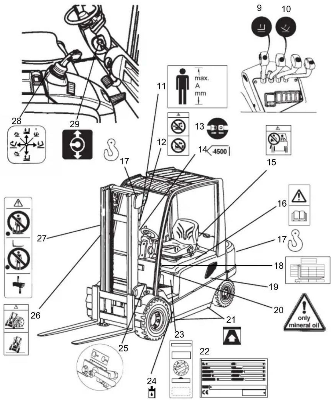
Warning and information labels such as load diagrams, sling points, and ID plates must be readable at all times and must be renewed, if necessary.
text_image
Technical diagram of a forklift with numbered parts and safety symbols, including warning signs, safety indicators, and industrial equipment.| Item Description | |
| 9 “Lift/lower” notice | |
| 10 “Forward/reverse tilt” notice | |
| 11 “Maximum body size” notice | |
| 12 | “Travel with raised load, mast forward tilt with raised load prohibited” notice |
| 13 "Attach safety restraint belt" notice | |
| 14 Lift limit | |
| 15 “Do not carry passengers” warning | |
| 16 Attention: Read operating instructions. | |
| 17 Strap points for lifting by crane | |
| 18 “Capacity” notice | |
| 19 Serial number, on chassis below side panel | |
| 20 “Mineral oil” notice | |
| 21 Jack contact points | |
| 22 Data plate | |
| 23 Test sticker (○) | |
| 24 “Add hydraulic oil” notice | |
| 25 “Spring-loaded brake” notice | |
| 26 “Procedure when truck in danger of tipover” notice | |
| 27 | "Do not stand under load handler” / “Do not stand under load handler” / “Risk of trapping when mast extended” combined notice |
| 28 “Hydraulic function (Multi-Pilot)” notice | |
| 29 “Steering column adjustment” notice | |
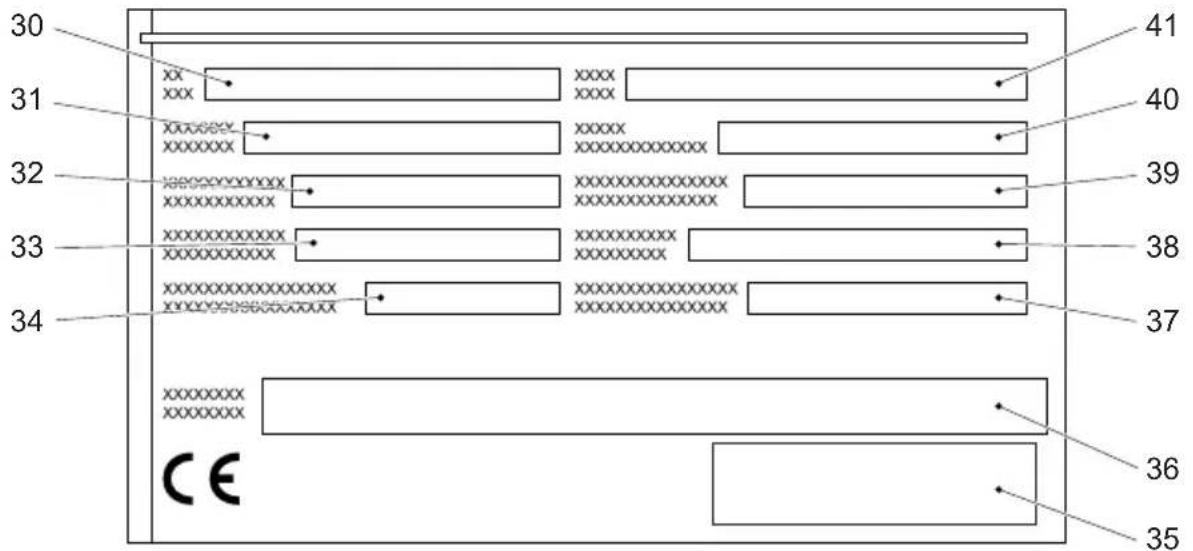
4.1 Identification plate, truck
text_image
30 31 32 33 34 41 40 39 38 37 36 35 CE| Item | Designation Item Designation | ||
| 30 | Type 36 Manufacturer | ||
| 31 | Serial No. 37 Min./max. battery weight in kg | ||
| 32 | Rated capacity in kg 38 Drive power in kW | ||
| 33 | Battery: Voltage V 39 Load centre distance in mm | ||
| 34 | Empty weight without battery in kg 40 | Year of manufacture | |
| 35 | Manufacturer logo 41 Option |

In the event of queries relating to the truck or spare part orders, please state the serial No. (31) of the truck.
4.2 Truck load diagram
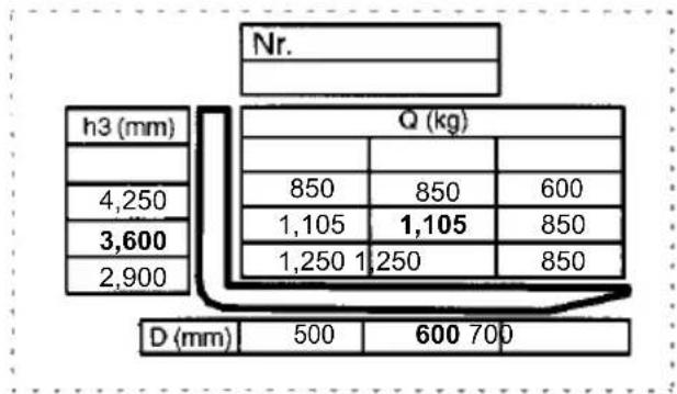
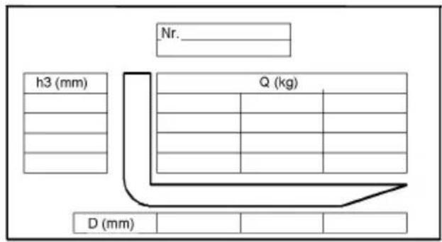
The truck load diagram indicates the carrying capacity Q kg of the truck with the lifting mast in vertical position. The table shows the maximum carrying capacity at a standard load centre distance D (in mm) and the desired lifting height H (in mm).
Example:
other
| Dimension | Value | |---|---| | h3 (mm) | 4,250 | | h3 (mm) | 3,600 | | h3 (mm) | 2,900 | | Q (kg) | 850 | | Q (kg) | 1,105 | | Q (kg) | 1,250 | | Q (kg) | 1,250 | | Q (kg) | 850 | | Q (kg) | 850 | | Q (kg) | 600 | | Q (kg) | 850 | | Q (kg) | 850 | | D (mm) | 500 | | D (mm) | 600 | | D (mm) | 700 | Nr. : | Position Label: Nr. : | Subtitle: Q (kg): | Horizontal Labels: d(mm): 500, 600, 700 | | Horizontal Labels: h3 (mm): 4,250, 3,600, 2,900 | | Horizontal Labels: D (mm): 850, 1,105, 1,250, 850 | | Horizontal Labels: Q (kg): 850, 1,105, 1,250, 850 | | Horizontal Labels: D (mm): 850, 1,250, 850 | | Horizontal Labels: Q (kg): 850, 1,105, 1,250, 850 | | Horizontal Labels: D (mm): 850, 1,250, 850 | The chart displays a single vertical line at position 4 for reference to the 'Q' axis.Example for determining the maximum carrying capacity:
At a load centre distance of D = 600 mm and maximum lifting height H = 3,600 mm the maximum carrying capacity Q = 1,105 kg.
4.3 Fork arm load diagram (basic device)
The fork arm load diagram indicates the carrying capacity Q of the truck in kg. In the diagram the maximum carrying capacity for different load centres D (in mm) is shown.
text_image
Nr. h3 (mm) Q (kg) D (mm)4.4 Attachment load diagram
The attachment load diagram indicates the carrying capacity Q of the truck in connection with the respective attachment in kg. The attachment serial number indicated in the load diagram must correspond to the ID plate of the attachment, since the manufacturer must state the carrying capacity specially for each attachment. It is indicated in the same way as the carrying capacity of the truck itself and must be determined accordingly.
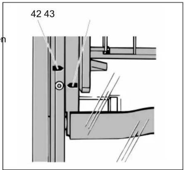
The arrow markings (42 and 43) at the inner respectively outer mast indicate to the driver that the lift limitations prescribed in the load diagram have been reached.
text_image
42 43C T r a n s p o r t a t i o n a n
1 T r a n s p

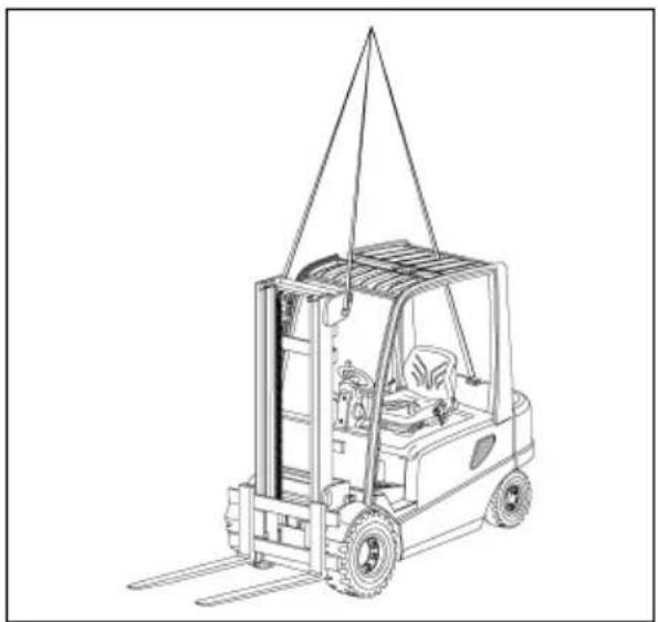
Only lifting gear of adequate capacity must be used
(loading weight = own weight + battery weight; see identification plate of the truck).
- Safe parking of the t (refer to chapter E)
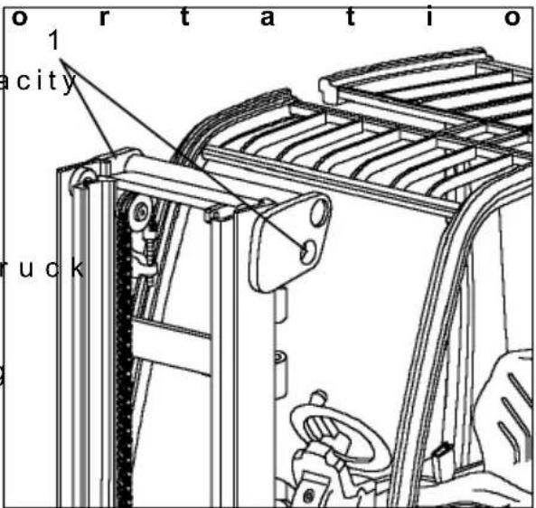
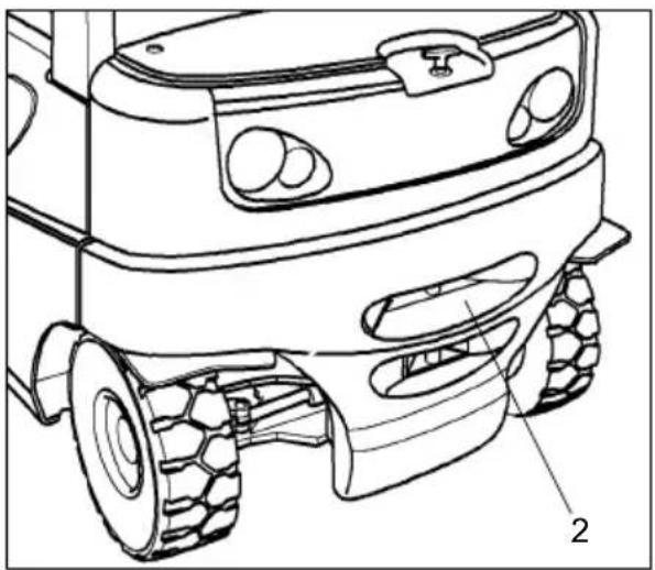
- Fasten hoisting gear at lifting mast crossbeam (1) and at trailer coupling (2).
text_image
orientation city truck
Transporting by crane is only provided for transport for first commissioning.
For application conditions that require frequent shipment (changing usage locations) it is required to consult the manufacturer.

Hoisting belts or chains may only be hooked into the top lug of the counterweight and the lugs of the end crosshead (lifting mast).
The lifting mast must be fully tilted back. The hoisting belt or chain at the mast must have a minimum free length of 2 m.
natural_image
Line drawing of a forklift lifting a load, no text or symbols present
The crane hoisting gear must be attached in such a way that it cannot touch any attached components or the overhead guard during lifting.
natural_image
Technical line drawing of a robotic vehicle showing front wheel, rear wheels, and gear (no text or symbols)2 S e c u r i n g t h e t

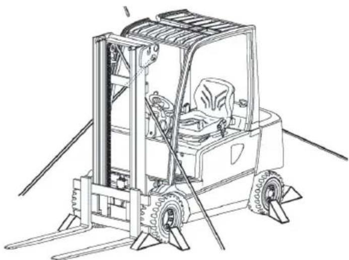
The fork lift truck must be properly secured with wedges and restraints during transport on a lorry or trailer. The lorry or trailer must be equipped with lashing rings and a wooden floor. Perform loading with suitably trained specialist staff according to the recommendations of VDI 2700 and VDI 2703 guidelines. Correct dimensioning and implementation of load securing measures is required for every separate case.

To lash down the fork lift truck with the lifting mast installed use the eyes on the top cross beam of the mast and the trailer coupling pin.
natural_image
Line drawing of a forklift carrying a truck, no text or symbols presentLashing and wedging with the lifting mast installed

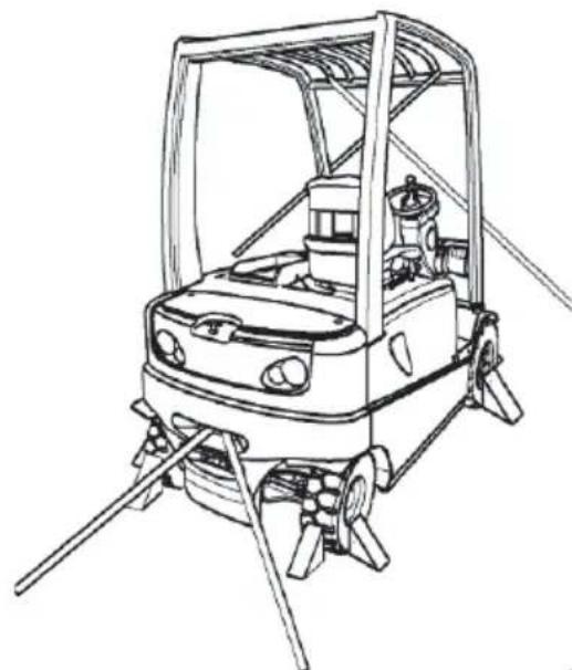
To transport the fork lift truck without lifting mast perform lashing across the overhead guard front.
natural_image
Line drawing of a forklift with no text or symbolsLashing and wedging without lifting mast

natural_image
Technical line drawing of a forklift with dimensional annotations (no text or symbols)Approximate centre of gravity
3 C o m m i s s i o n i n g

Commissioning and instructing drivers may only be performed by appropriately trained personnel.

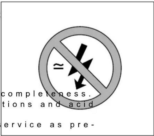
The truck must only be operated on battery current. Rectified alternate current will damage the electronics. Cables connected to the battery (trailing cables) must be less than 6 meters in length.
In order to prepare the truck for work following delivery or transportation, the following operations must be performed:
- Check equipment for
- Check battery connec level (refer to chapter D, section 6).
- Bring the truck into s
scribed
(refer to chapter E, section 3).
text_image
completeness. tions and acid ervice as pre-4 M o v i n g t h e t r u
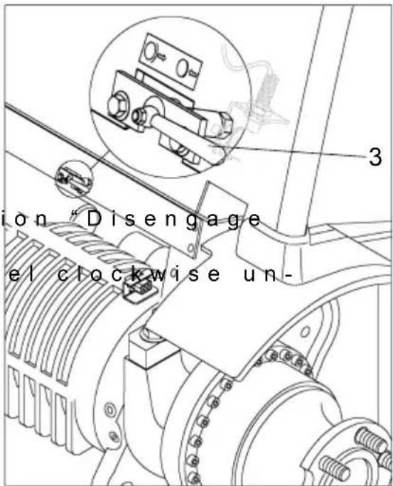
In order to move the truck without electricity supply, the spring-loaded brake must be disengages as follows:

Before the driver leaves the truck with the spring-loaded brake disengaged he must secure the truck against accidental rolling away.
- Set lever (1) to posit spring-loaded brake".
- Turn the steering wheel pressure builds up in the hydraulics circuit and the spring-loaded brake is disengaged. (This can be noticed by checking whether the brake pedal functions normally, if the brake is still engaged you feel an immediate resistance). The drive wheels are no longer blocked resp. decelerated by the spring-loaded brake. The foot
brake will still be fully operative. While turning the steering wheel the foot brake must not be actuated.
text_image
ion "Disengage el clockwise un-
Prior to recommissioning the truck by applying power again, lever (1) must be set to the right to "Travel position". The truck is now ready to operate in travel position.
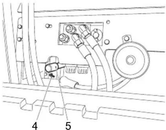
Trucks with Multifunction Steering Wheel (○)
- Set lever (4) to the left position "Release accumulator brake"
- Carry out a sufficient number of pump strokes with the lever (5) until pressure builds up in the hydraulic circuit and the spring-loaded accumulator brake is released. The drive wheels are no longer blocked / braked by the spring-loaded brake.

Before starting the truck again with power supply, the lever (4) must be reset to the right in the "travel" position. The truck can only operate in the travel position.
text_image
Technical diagram of an electrical panel with labeled components 4 and 5, showing wiring connections and a valve mechanism.5 Steering the truck without its own drive system (○)

The truck cannot be steered if the steering hydraulic system or the truck electronics are damaged.
To steer the truck without power, apply the steering as follows.
-Turn the EMERGENCY DISCONNECT and key switch off.
- Secure the truck to prevent it from rolling away
- Place a spanner on the hex. bolt (6) and turn the drive to the required steering position.
6 Towing the truck
- Connect a tow-rod/towing rope at the trailer coupling of the recovery vehicle and at the truck to be towed.
- Disconnect the battery plug (observe item D3!).
- Disengage the parking brake.

There must be a person for steering the truck on the driver seat of the truck to be towed. Tow the truck at walking speed!

As the steering booster is not switched on, the truck can only be steered with increased effort.

For trucks with a multifunctional steering wheel (○) only authorised persons may only tow the truck out of the hazard area for slow shunting. The truck can only be moved using a recovery truck and a tow bar. The emergency steering must be applied as described in “Steering the Truck without its own Drive System”
D Battery - Servici ment
1 S a f e t y r e g u l a t
The truck must be parked and rendered safe before any operations on batteries are undertaken (refer to chapter E).
Servicing staff: Recharging, servicing and replacing of batteries must only be performed by qualified personnel. The instructions contained in this operating manual, and the instructions of the manufacturer of the battery and of the battery recharging station, must be observed when performing the above operations.
Fire protection measures: Smoking and naked flames are not permitted when handling batteries. No inflammable substances or spark-generating materials must be present or stored within a distance of 2 meters of the truck parked for battery recharging. The location must be well ventilated and fire fighting equipment must be kept ready.
Servicing of batteries: The battery cell screw caps must be kept dry and clean. Terminals and cable shoes must be clean, lightly greased with pole grease and must be securely tightened. Batteries with bare terminal posts must be covered using a non-skid insulating mat.
Disposal of the battery: Batteries must only be disposed of as stipulated in the national environmental protection regulations or waste disposal provisions. The manufacturer's specifications for the disposal must be heeded.

Before closing the battery hood, make sure that the battery cable cannot be damaged.

Batteries contain dissolved acid which is toxic and caustic. For this reason, protective clothing and goggles must be worn whenever work is undertaken on batteries. Avoid physical contact with battery acid.
If clothing, skin or eyes accidentally come into contact with battery acid, liberally flush the affected parts with clean water. Consult a doctor when skin or eyes come into contact with battery acid. Spilled battery acid must be immediately neutralized.

Only batteries with closed tray may be used.
2 B a t t e r y t y p e s
In dependence on the application, the truck is equipped with different battery types. The following table shows which standard combinations are possible, similar to DIN 43535, with indication of the capacity.
| EFG 422 80 V - 4PzW - battery 480 Ah80 V - 4PzS - battery 560 Ah |
| EFG 425k 80 V - 4PzW - battery 480 Ah80 V - 4PzS - battery 560 Ah80 V - 4PzS - battery 600 Ah |
| EFG 425/430 80 V - 5PzW - battery 600 Ah80 V - 5PzS - battery 700 Ah80 V - 5 PzS - battery 750 Ah |
The battery weight is indicated on the rating plate of the battery.

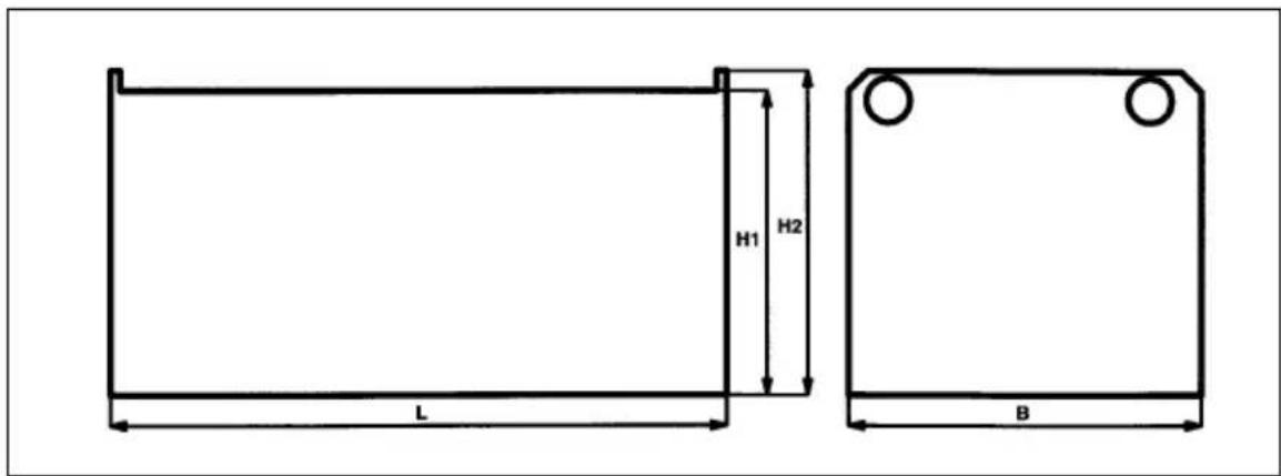
Battery weight and dimensions have a considerable influence on the stability of the truck. For this reason, the dimensions and weight of the batteries must correspond to the following table and drawing. Operation of the truck with non-conforming batteries is only allowed with prior approval by the manufacturer.
| Drive battery 80 V | similar to DIN 43535 | |||||
| Truck | Dimension (mm) Nom. weight | (-5/+8%)in kg | ||||
| L max. B | max. H1 +/- 2 mm | H2 +/- 2 mm | ||||
| EFG 422 10 | 28 711 769 | 784 1558 | 480 - 560 Ah | |||
| EFG 425k/425ks | 1028 711 | 769 784 1558 | 480 - 600 Ah | |||
| EFG 425/425s/430 | 1028 855 | 769 784 1863 | 600 - 750 Ah | |||
text_image
H1 H2 L B3 Opening the battery hood with support system (○)

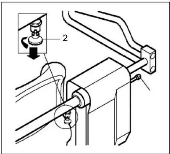
If the truck is equipped with a safety restraint system, the battery panel can only be opened if the safety gates are in the home position (horizontal), the gate on the driver's side folded inward and secured with the locking knob.
- For the automatic restraint system (ERS), engage the locking knob (2) and fold the gate in.
- With the ERS-AS automatic restraint system, the gate is automatically folded and maintained in the right position.
See Chapter E "Safety Restraint System".
text_image
Technical diagram showing mechanical assembly with labeled component '2' and directional arrow indicating rotation or movementMechanical restraint system with electronic control (HRS-E with folding gate)
To open the battery panel fold the left restraint gate down and in. After closing the battery panel fold the gate out and up.
Electronic Restraint System (ERS with folding gate)
To open the battery panel manually fold down the gate and lock it with the locking knob (2). Fold the gate in.
After closing the battery panel (charging completed) fold the gate out, unlock the locking knob (2) and manually fold the gate up.
Electronic safety restraint system with automatic closing (ERS-AS with gate)
When the battery panel is opened the gate automatically flips to the home position (horizontal position, see chapter E, "Safety Restraint System (Automatic) Operating Instructions" and automatically locks. Fold the gate in by hand.
When closing the battery panel fold the gate out, the gate automatically opens and unlocks.
4 E x p o s i n g t h e b
STOP
Park and lock the truck (see chapter E).
- Release steering col push steering column forward and se- cure in this position.
STOP
Pay special attention when unlatching and latching the control valve cover.
With MULTI PILOT or multifunction steering wheel:
- Pull control valve co til it engages.
- Carefully fold back b driver's seat (3).
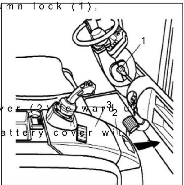
text_image
mn lock (1), ver (2) forward 2 un- battery cover withWith SOLOPILOT:
- Unlatch control valve pressing lever (4) and swivel forward.
- Carefully fold back b driver's seat.
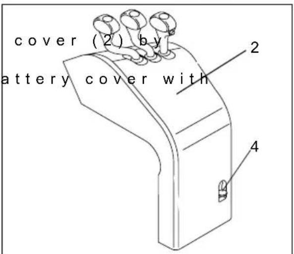
text_image
cover (2) by battery cover with 2 4STOP
Connecting and disconnecting the battery plug and socket is only permitted with the main switch and charger switched off.
- Unplug battery conne - If necessary, remove mats from the battery.
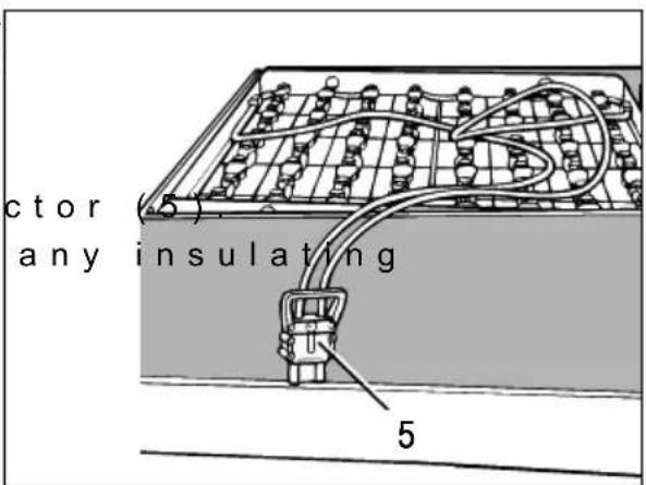
text_image
ctor any insulating 55 C h a r g i n g t h e b
- Expose the battery (refer to chapter D, section 3).

Connecting and disconnecting battery and charger is only permitted with the charger switched off.
The surface of the battery cells must be uncovered during charging operation, to guarantee sufficient aeration. Do not put any metal objects on the battery.

Check all cable and plug connections for visible damages prior to charging.
- Connect charging cable charging station to battery plug (5). - Charge the battery adstructions of the battery and charger manufacturer.
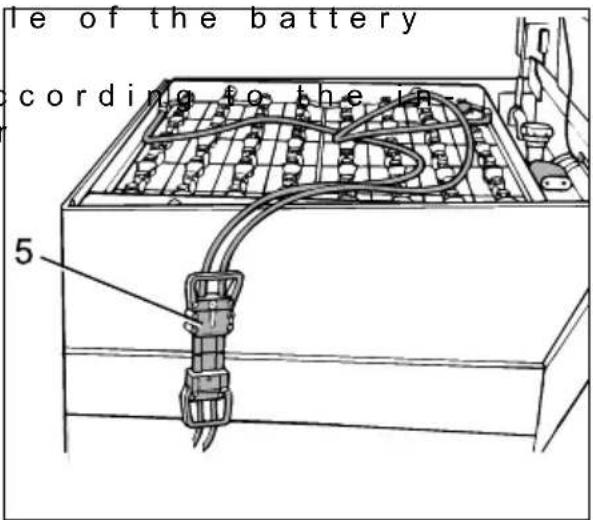
text_image
le of the battery cording to the r 5
All safety instructions as provided by the battery supplier and battery charger supplier must be strictly observed. During charging, the battery cover must remain open at all times, so that any gas generated by the charging process can volatile. No not use any open fire or light. Explosion hazard!
5.1 Charger socket (○)
- Park the truck securely (see chapter E)

Always connect and disconnect the battery and charger when the charger is switched off.
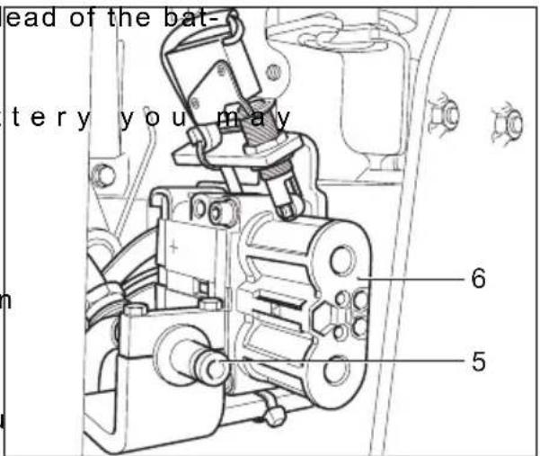
- Connect the charger tery charger station to the charger socket (6).
- Depending on the bat need to connect the water (5) to the battery charger station.
The charging process is monitored electrically. The truck is automatically prevented from being operated and a fan inside the truck is activated to ventilate the battery.
text_image
ead of the bat- tery you may 6 5
Always check the fans each time you charge.
- Switch on the battery charging station and charge the battery and charging station manufacturers' instructions.

Use only chargers with a max. 160 A charging current.

It is essential to follow the safety regulations of the battery and charging station manufacturers. The fan must be in permanent operation during charging to allow the charging gases to dissipate. Do not use fire or naked flames. Risk of explosion!
6 R e m o v i n g a n d i

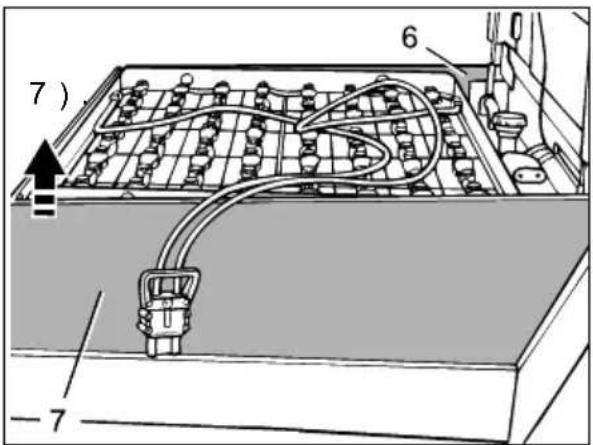
The battery must not be lifted above the collision guard at the rear wall, otherwise the ventilator or seat hood may be damaged.
- Exposing the battery (refer to chapter D, Section 3). - Pull out side wall (6,
text_image
7) 6 7
To prevent short-circuits, batteries with exposed poles or cell connectors must be covered using a rubber mat. When changing batteries with the aid of a crane, ensure that the crane is of adequate capacity (the battery weight is indicated on the battery identification plate at the battery trough). The crane hoisting gear is routed through the recess at the overhead guard and must exert vertical pulling action, so that the battery trough is not crushed. The hooks must be fastened in such a way that they cannot fall onto the battery cells when the crane hoisting gear is slackened.
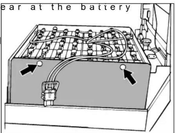
- Attach the hoisting trough. - Lift the battery by means of the hoisting gear to the right over the frame and then swivel it outwards to the side.
text_image
ear at the battery- Replacing the battery is done in reverse order.

When replacing the battery, make sure only to use the same type as replacement. After reinstallation of the battery, visually check all cables and connectors for damage. All covers and side doors must be securely closed.

During replacement/installation of the battery, pay attention that the battery is tight in the battery box of the truck.
7 C I o s i n g b a t t e r
With MULTI PILOT or multifunction steering wheel::
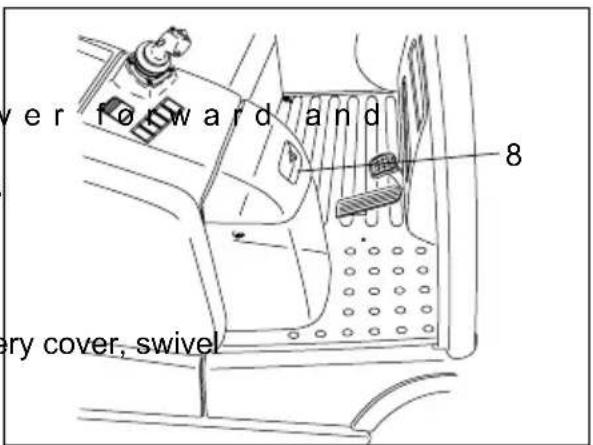
- Pull control valve cover simultaneously unlatch it by pressing lever (8). Control valve cover moves back by itself.
With SOLOPILOT:
- After closing the battery control valve cover to the back until it engages.
text_image
ver forward and 8 very cover, swivel8 B a t t e r y d i s c h a
hour meter
Battery discharge indicator: The charging condition of the battery is indicated on the information and service display.
!
The standard setting of the battery discharge indicator / discharge monitor is made using standard batteries.
When using maintenance-free batteries, the display must be readjusted. The setting must be performed by customer service engineers. If this setting is not performed, the battery might suffer damage caused by exhaustive discharge.
When reaching the last 10 % of the available capacity, the warning symbol flashes.
When a battery is discharged to the permissible discharge level, the battery symbol is displayed empty.
Battery discharge monitor: As soon as the capacity falls below the residual battery capacity, the lifting function will be switched off. This is indicated by a message displayed on the information and service display.
In order to complete the lifting process, the key switch must be switched off and on again, which enables lifting for another 30 to 40 seconds.
→
Lifting will only become possible again after the battery has been recharged to at least 40 %.
Operating hour meter: The operating hours are indicated next to the charging state of the battery. The service hours are counted when the truck is switched on and the seat switch is closed.
E O per a t i o n
1 S a f e t y R e g u l a t
Driver authorisation The forklift truck may only be used by suitably trained personnel, who have demonstrated to the proprietor or his representative that they can drive and handle loads and have been authorised to operate the truck by the proprietor or his representative.
Driver's rights, obligations and responsibilities: The driver must be: informed of his rights and duties; trained in the operation of the forklift truck; and familiar with the contents of these operating instructions. The driver shall be afforded all due rights. Safety shoes must be worn with pedestrian operated trucks.
Unauthorised use of truck: The driver is responsible for the truck during the time it is in use. He shall prevent unauthorised persons from driving or operating the truck. Do not carry passengers or lift other people.
Damage and faults: The supervisor must be immediately informed of any damage or faults to the forklift truck. Trucks which are unsafe for operation (e.g. wheel or brake problems) must not be used until they have been rectified.
Repairs: The driver must not carry out any repairs or alterations to the industrial truck without the necessary training and authorisation to do so. The driver must never disable or adjust safety mechanisms or switches.
Hazardous area: A hazardous area is defined as the area in which a person is at risk due to truck movement, lifting operations, the load handler (e.g. forks or attachments) or the load itself. This also includes areas which can be reached by falling loads or lowering operating equipment.
STOP
Unauthorised persons must be kept away from the hazardous area. Where there is danger to personnel, warning shall be sounded in good time. If unauthorised personnel are still within the hazardous area the truck shall be brought to a halt immediately.
Safety devices and warning signs: Safety devices, warning signs and warni instructions shall be strictly observed.
!
Trucks with reduced headroom are equipped with a warning sign within the driver's line of sight. The max. recommended body size indicated on this sign must be observed.
| Item | Control / Display | Function | |
| 1 | Steering wheel | ● | Steers the truck with 5 full turns from left to right. |
| 2 | Multi-function display | ● | Displays the main travel, lift parameters, warning displays, error messages and service displays, as well as battery discharge and elapsed hour display. |
| 3 | P a r k i n switch) | g | Only apply manually when operating brakes fail. g Normally the parking brake (spring-loaded accumulator brake) automatically applies when the truck is idle.Visual display:Red = Parking brake appliedGreen = Parking brake released |
| 4 | Steering column stop | ● | To adjust and fix the steering column to the required distance. |
| 5 | Key switch | ● | Switches current on and off. Removing the key prevents the truck from being switched on by unauthorised personnel. |
| 6 | Accelerator pedal | ● | The travel speed is infinitely controlled. |
| 7 | B r a k e | p | e d a l ● Brakes the truck. |
| 8 | T r a v e l MULTI PILOT HornAuxiliary hydraulics (ZH3) | ○○○○ | Sets the required travel direction. n s wControls the lifting mast functions.Triggers a warning signal.Toggles from ZH2 to ZH3 |
| 9 | O p t i o n switch | a | e.g. display for work lights op m e n t |
| 10 EMERGENCY DISCONNECT isolator | ● | Switches power supply on and off. | |
| 11 For dual pedal control: “Reverse” accelerator pedal | ○ | The truck travels in reverse direction when applied The travel speed is infinitely controlled. | |
| 12 For dual pedal control: Brake pedal | ○ | Brakes the truck. | |
| 13 For dual pedal control: “Forward” accelerator pedal | ○ | The truck travels forward when applied The travel speed is infinitely controlled. | |
| 14 | Travel direction switch | ● | Sets the required travel direction. |
| 15 | Horn | ● | Triggers a warning signal. |
| 16 SOLO-PILOT Lift - Lower | ● | Lifts / lowers the forks | |
| 17 SOLO-PILOT Mast - tilt | ● | Tilts the forks forward / backward. | |
| 18 SOLO-PILOT Auxiliary hydraulics (ZH1) Sideshift | ○ | Moves the forks to the right / left. | |
| 19 SOLO-PILOT Auxiliary hydraulics (ZH2) | ○ | Used for hydraulic attachments. | |
| 20 Toggle switchAuxiliary hydraulics (ZH3) | ○ | Toggles from ZH2 to ZH3 | |
| ● = Standard equipment ○ = Optional Equipment | |||
I e
i t c
Truck with MULTI PILOT
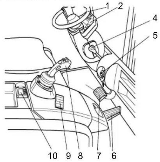
text_image
Technical diagram of a car interior with numbered components for identification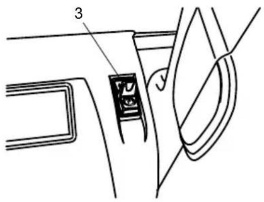
text_image
Technical diagram showing a mechanical component with labeled parts 3 and 4, likely illustrating a turning or assembly process.Twin pedal control

text_image
11 12 13Truck with SOLO PILOT
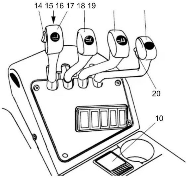
text_image
14 15 16 17 18 19 20 10Truck with MULTIPILOT / Fingertip multifunction armrest (○)
| Item | Control / Display | Function | |
| 21 | Control panel ○Displays the main travel, lift parameters, warning displays, error messages and service displays, as well as battery discharge and elapsed hour display. | ||
| 22 | EMERGENCY DISCONNECT | ○Switches power supply on and off. | |
| 23 | Key switch ISM | ○ | Switches current on and off. Removing the key prevents the truck from being switched on by unauthorised personnel. |
| 24 | Fingertip | ○ | Same operation as for Solopilot items 16; 17; 18; 19 |

text_image
21 22 23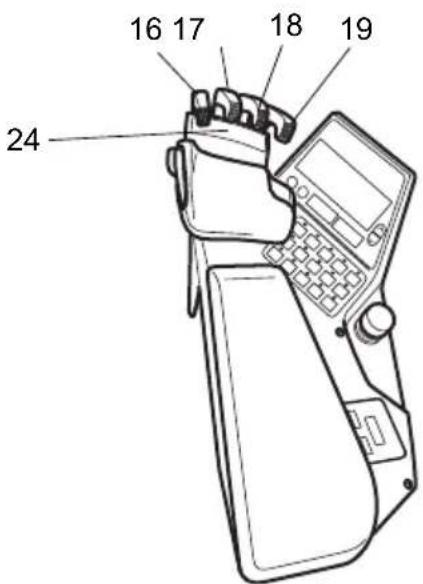
text_image
16 17 18 19 24Trucks with Multifunction Steering Wheel (○)
| Item | Control / Display | Function | |
| 21 | Control panel ○ Displays the main travel, lift parameters, warning displays, error messages and service displays, as well as battery discharge and elapsed hour display. | ||
| 22 | EMERGENCY DISCONNECT | ○ | Switches power supply on and off. |
| 23 | Key switch ISM | ○ | Switches current on and off. Removing the key prevents the truck from being switched on by unauthorised personnel. |
| 25 | Auxiliary hydraulics (ZH2) | ○ | Used for hydraulic attachments. |
| 26 | Mast - tilt | ● | Tilts the forks forward / backward. |
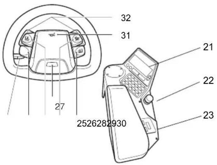
| 27 | Toggle switch Auxiliary hydraulics (ZH3) | ○ | Toggles from ZH1 to ZH3→ when changing from ZH1 to ZH3, the ZH3 function is operated with button 29. |
| 28 | Lift - Lower ● Lifts / lowers the forks | ||
| 29 | Auxiliary hydraulics (ZH1) Sideshift | ○ | Moves the forks to the right / left. |
| 30 | Height adjuster Adjusts and sets the steering column at the required height. | ||
| 31 | Horn ● Sends a warning signal. | ||
| 32 | Travel direction switch ● Sets the required travel direction. | ||
text_image
32 31 27 21 22 23 25262829302.1 Instrument panel switches
| Function | |
 | Hazard warning switch |
  | “Beacon / parking light” switch |
 | Windscreen wiper / washer system switchPosition 1 “Windscreen wiper on”Position 2 “Washing system on” |
2.2 Control panel switches
| Function | |
 | “Lift cutout” override switch |
 | “Inching” switch |
 | “Seat heater” switch |
 | “Truck lighting” switch (parking light / dimmed headlights) |
 | “Work lights” switch |
2.3 Multi-function display
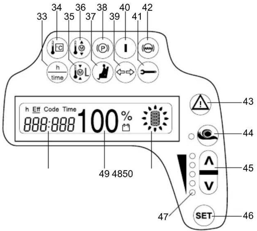
The multi-function display shows the operating data, the battery charge, the service hours and error details and information. Graphic illustrations on the multi-function display act as warning indicators.
text_image
33 34 35 36 37 38 39 40 41 42 h time h Eff Code Time 888:888 100 % 49 4850 43 44 45 47 SET 46| Item Display | |
| 33 Service hours / time toggle switch | |
| 34 Controller overtemperature | |
| 35 Pump motor overtemperature | |
| 36 Drive motor overtemperature | |
| 37 | Seat switch / belt lock control (○) |
| 38 Parking brake applied | |
| 39 Travel direction indicator (○) | |
| 40 Truck operational (key switch “ON”) | |
| 41 Service display / UVV display | |
| 42 Brake fluid level too low | |
| 43 | Lights up for errors or when battery capacity is less than 10% |
| 44 Crawl speed switch | |
| 45 Program selector | |
| 46 SET key | |
| 47 Operating program display (programs 1 to 5) | |
| 48 Travel direction and wheel position display | |
| 49 Battery capacity display | |
| 50 | Time and service hours or diagnostics and error display |
2.3.1 Warning displays, buttons and switches
The following conditions are displayed or switched on:
| Item Display / Function | |
| 33 Hourmeter - Time Toggle Switch- Service hours during which truck key switch is ON-EFF service hours can be switched ON or OFF via a code.- Time display | |
| 34 Controller overtemperature-Lights up to indicate controller overtemperature- Performance is continually reduced in relation to the temperature | |
| 35 Pump motor, steering booster overtemperature-Monitors the temperature of the pump motor and the steering booster- Performance is reduced if the temperature is excessive | |
| 36 Drive motor overtemperature-Monitors the temperature of the drive motor- Performance is reduced if the temperature is excessive | |
| 37 Seat switch / belt lock control (○)- Seat switch not closed-Truck operational, but driver's seat not occupied-Truck operational, belt lock not closed | |
| 38 Parking brake applied-Truck operational, parking brake applied | |
| 39 Travel direction indicator ○- For lighting with a flashing indicator system | |
| 40 Truck operational- Key switch ON | |
| 41 Service display / UVV display- Service interval exceeded (1000 service hours) or annual UVV test due (flashing indicator). | |
| 42 Insufficient brake fluid- The brake fluid level can be checked through sensors on the brake fluid reservoir. | |
| 43 WARNING-Lights up to indicate error- Flashes when battery capacity is less than 10% | |
| 44 Crawl speed switch- Travel speed max. 6 km/h (adjustable) | |
| 45 Program selector-Up and down keys | |
| 46 SET key- Selects special functions | |
| 47 Operating program display- Displays the selected travel program (1 to 5) |
2.3.2 Displays
| Item Function |
| 48 Travel direction and wheel position display– Indicates the pre-selected travel direction (forward or reverse) or the position of the steered wheels. |
| 49 Battery capacity display in %Indicates the available residual capacity.0% display = battery 80% discharged.For a 10% display the warning indicator flashes (42).At 0% capacity lifting is cut out after 30 to 40 seconds. |
| 50 Operating hours display / Error display– Operating hours display:– eff: shows the overall working timeError display:– if an error (Err) or a warning (Inf) occurs, the operating hour display disappears. The error code is displayed.– If several errors occur they are displayed alternately and a warning is sounded. |
2.4 Control panel (○)
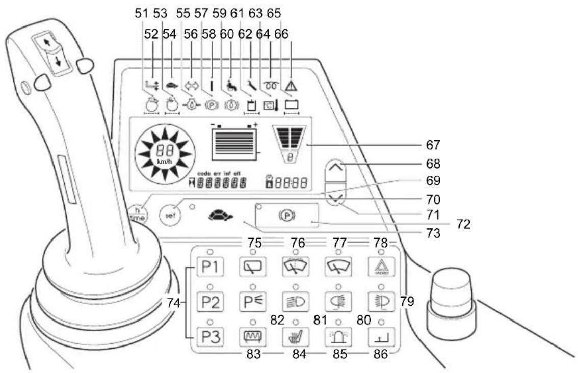
The control panel display shows the operating data, the battery charge, the service hours and error details and information. Graphic illustrations on the control panel act as warning indicators.
text_image
51 53 55 57 59 61 63 65 52 54 56 58 60 62 64 66 88 km/h code arr inf att P1 P2 P3 75 76 77 78 79 80 81 82 83 84 85 86 67 68 69 70 71 72 73 742.4.1 Control panel displays
| Item Display | ||
| 51 No function | ||
| 52 No function | ||
| 53 No function | ||
| 54 Cravlspeed control light | ||
| 55 No function | ||
| 56 | Travel direction indicator- For lighting with a flashing indicator system | |
| 57 | Parking brake applied-Truck operational, parking brake applied | |
| 58 | Truck operational-Key switch ON | |
| 59 No function | ||
| 60 | Seat switch / belt lock control ○)- Seat switch not closed-Truck operational, but driver's seat not occupied-Truck operational, belt lock not closed | |
| 61 No function | ||
| 62 | Service Display- Service interval exceeded (1000 service hours) or annual UVV test due (flashing indicator). | |
| 63 | Controller overtemperature-Lights up to indicate controller overtemperature- Performance continually reduces with respect to the temperature | |
| 64 No function | ||
| 65 No function | ||
| 66 | WARNING-Lights up to indicate error- Flashes when battery capacity is less than | |
| 67 Driver's display | ||
2.4.2 Control panel buttons
text_image
51 53 55 57 59 61 63 65 52 54 56 58 60 62 64 66 88 km/h code arr inf sit 67 68 69 70 71 72 73 74 75 76 77 78 P1 P2 P≤ P3 808182 86858483| Item Function | ||
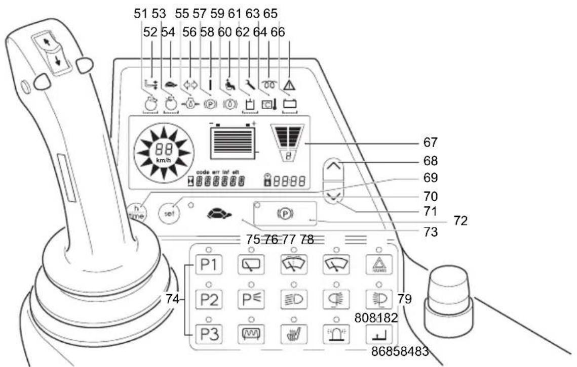
| 68 Se |  travel program (go up to other modes) travel program (go up to other modes) | |
| 69 Hc |  ter / time toggle switch ter / time toggle switch | |
| 70 |  | SET button- Selects special functions |
| 71 Se |  travel program (go down to other modes) travel program (go down to other modes) | |
| 72 |  | Parking brakeApplies / releases parking brake |
| 73 |  | Crawl speed switch- Travel speed max. 6 km/h (adjustable). |
| 74 Or |  not used not used | |
| 75 Sv |  s roof window wipers on and off, interval setting s roof window wipers on and off, interval setting | |
| 76 Sv |  s windscreen washing system on and off. s windscreen washing system on and off. | |
| 77 Switches | window wipers on and off, interval setting | |
| 78 Switches | warning indicator system on and off. | |
| 79 Switches | front headlights on and off. | |
| 80 Switches | rear headlights on and off. | |
| 81 Switches | dipped lights on and off. | |
| 82 Switches | parking light on and off. | |
| 83 Switches | rear window heating on and off. | |
| 84 Switches | seat heating on and off. | |
| 85 Switches | the beacon on and off. | |
| 86 “Lift cutout” | override button | |
2.4.3Displays

text_image
87 km/h code err inf eff 88 899091| Item Function |
| 87 Battery capacity display– Battery discharge status |
| 88 Profile number (travel / lift profile 1, 2, 3, 4 and 5) |
| 89 Hourmeter display– Time display– Residual time display with on-board battery(hours : minutes) |
| 90 Error display:– if an error (Err) or a warning (Inf) occurs, the operating hour display disappears.– If several errors occur they are displayed alternately. A warning is sounded.– eft: shows the overall working time |
| 91 Travel direction, speed and wheel position display– Indicates the pre-selected travel direction (forward or reverse) or the position of the steered wheels. |
2.5 Setting the time
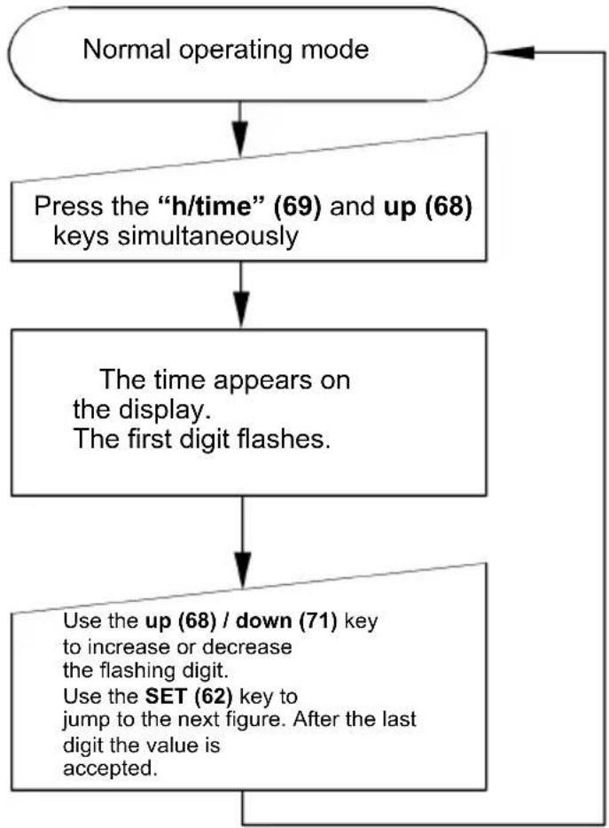
flowchart
graph TD
    A["Normal operating mode"] --> B["Press the "h/time" (69) and up (68) keys simultaneously"]
    B --> C["The time appears on the display.<br>The first digit flashes."]
    C --> D["Use the up (68) / down (71) key to increase or decrease the flashing digit.<br>Use the SET (62) key to jump to the next figure. After the last digit the value is accepted."]
    D --> E["End"]
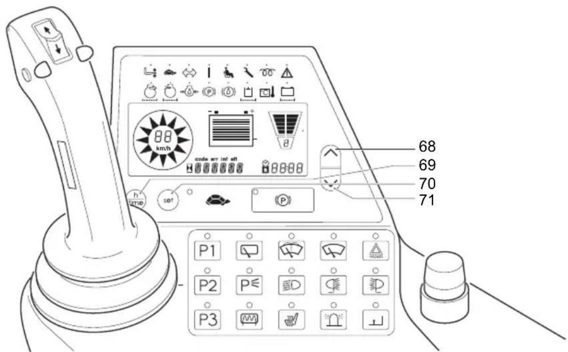
text_image
68 69 70 71 P1 P2 P32.6 Warning registration on driver's display
| Display Meaning | |
| INFO 02 - No | direction selected when truck powered up, no wheel position displayed-Travel direction changed to neutral setting during operation, wheel position display alternates between forward and reverse. |
| INFO 05 (Optional setting for travel cutout input)Lift cutout active / independent of other conditions | |
| INFO 16 (Optional setting for travel cutout input)Travel cutout active / independent of other conditions | |
| INFO 35 Accelerator pedal zero position-Message can be adjusted to suit preference – either the zero position is only checked after power up or after every transition of the seat switch from the open to closed position. | |
| INFO 36 Hydraulics zero position-Message can be adjusted to suit preference - message displayed or not. | |
| INFO 40 OvertemperatureTraction or lift controller above 83°C.Traction or lift controller above 145 °C. | |
| INFO 90 Travel with handbrake on-Accelerator pedal applied while the handbrake switch is set to parking position. | |
| INFO 96 Hydraulics zero position on power up-a hydraulic function applied during power up-the hydraulic function applied will not be performed. | |
3 S t a r t i n g u p t h

Before commissioning or operating the truck, and before raising a load, the driver must ensure that there is nobody in the hazardous area and that the truck is safe to operate.
3.1 Checks and operations to be performed before starting daily work
Before starting the truck the driver must ensure it is safe to operate. Before starting work, check for example that
– the operating and parking brakes or the automatic brake (Emergency Stop) are working
-the fork tine retainer preventing the tines from moving is not defective
– the load handler does not show visible signs of damage (bent, cracks or heavy wear)
-the warning device is working
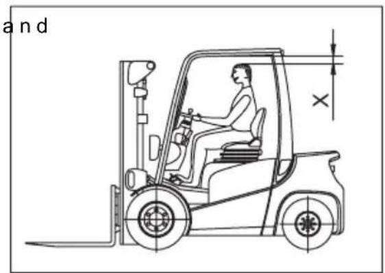
3.2 Trucks with reduced headroom X (○)

Failure to comply with the recommended body size may result in overload constitute a danger to the driver, possibly resulting in permanent damage caused by an unhealthy posture and excessive physical exertions on the part of the driver.
The owner must ensure that the truck operator does not exceed the maximum body size indicated.
The owner must also check that the drivers can sit normally, in an upright position without having to exert himself.
text_image
and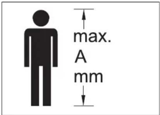
text_image
max. A mm3.3 Adjusting the driver's seat

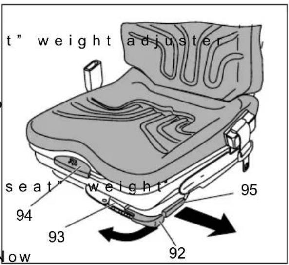
To achieve optimal seat cushioning, the driver's seat must be adapted to the driver's weight.
The driver's seat must be adapted to the driver's weight.
Adjusting the driver's weight:
- Pull the "driver's sea (92) in the direction of the arrow as far as the stop and then return it.

The previous weight setting is reset to the minimum value. The seat suspension can be set from 50 kg to 130kg
- Move the "driver's adjuster (92) again in the direction of the arrow until the corresponding weight marking on the "driver's seat" weight display (93) is reached. N return the "driver's seat" weight adjuster.
-Sit on the driver's seat.
text_image
t" weight adjuster seat" weight 94 93 92 lowAdjusting the backrest:
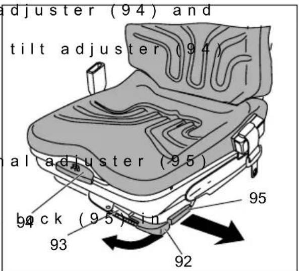
- Lift up the backrest a adjust the backrest tilt.
- Release the backrest to lock the backrest in position.
Adjusting the seat position:
- Pull up the longitudin and push the driver's seat forwards or backwards to the desired position.
- Engage driver's seat position again.
一
text_image
adjuster (94) and tilt adjuster (94) al adjuster (95) back (95) in 93 92 95
The driver's seat must be securely locked in the desired position. The driver's seat setting must not be changed during travel.

The procedure for adjusting the driver's seat applies to standard models. For other models, follow the manufacturer's setting instructions. When adjusting the seat make sure that all controls are within easy reaching distance.
3.4 Safety restraint belt

Put on the safety restraint belt each time before starting the industrial truck. The belt protects against serious injury.
Protect the belt from contamination (e.g. cover it when the truck is idle) and clean it regularly. Frozen belt locks or pulleys must be thawed out and dried to prevent them from freezing up again.

The dry temperature of the warm air should not exceed +60 °C.

Do not alter the belt setting. This will increase the risk of malfunctioning.
- Always replace the safety restraint belt after an accident. - Only original spare parts must be used for retrofits or repairs.

Damaged or non-operational belts must only be replaced by contractual dealers or branches.
Procedure in unusual situations

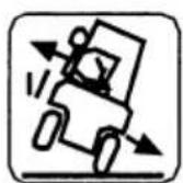
If the truck is about to tip over, under no circumstances should you the restraint belt and try to jump out. Jumping increases the risk of injury.
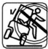
Correct procedure:
- Lean your upper body over the steering wheel.

- Grip the steering wheel with both hands and brace feet.
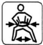
- Lean your body against the opposite direction of fall
Restraint belt operating instructions
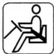
Before starting the truck carefully pull the belt out of the pulley, pull it tightly across your body and over your thigh, and engage it in the lock.

The belt must not be twisted when fastened.
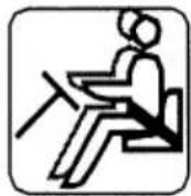
When operating the truck (e.g. travelling, lifting, lowering, etc.), sit as far back as possible so that your back is against the backrest.
The automatic locking retractor allows sufficient freedom of movement on the seat.

Sitting at the front edge of the seat affords less protection, as the belt is too long.

The belt is only to be used to secure one person.
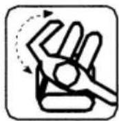
- After using the belt, push the red button and manually guide the tongue back to the retractor.

The automatic blocking system can be triggered if the seat belt tongue strikes the housing. This will prevent the belt from being extracted.
Deactivating the blocking system:
- Apply force to pull the belt 10mm – 15mm out of its housing. - Feed the belt back in to undo the automatic blocking system
The belt can now be extracted again.
Starting the industrial truck on steep slopes
The automatic blocking system locks the belt in the retractor when the truck is positioned on a steep slope. This prevents the belt from being pulled out of the retractor.

Carefully drive the truck off the slope and then put on the belt.

3.5 Safety Restraint System (○)

Never use the truck with a non-functional restraint system.
The restraint system must be checked by authorised specialist personnel after an accident.

Do not alter the restraint system.
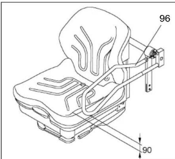
When the driver's seat is occupied, maintain a 90 mm gap between the gate (96) and the seat to ensure safety.
text_image
96 90Procedure in unusual situations

If the truck is in danger of tipping over, do not try to jump out. This will only increase the risk of injury.
Correct procedure
- Lean your upper body over the steering wheel.
– Grip the steering wheel with both hands and brace feet. - Tilt your body in the opposite direction of fall.
3.5.1 Safety restraint system (automatic) operating instructions (○)

Test the restraint system before starting the truck.
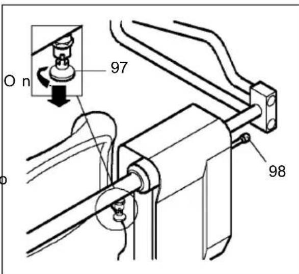
The stop knob (97) must not be engaged.
-Sit down on the seat -Turn the key switch "
After releasing the parking brake the two safety gates (LH and RH) close and lock automatically.
Make sure the safety gates are free to move.
After parking the truck and applying the handbrake, the safety gates open automatically.
text_image
O n 97 98The key switch should only be turned to "0" and removed when the safety gates have been opened.
If the event of a power failure, the restraint system can be unlocked by pulling the knob (98). The safety gates can be moved back manually.
Electronic Safety Restraint Sysetm (ERS with folding gate)
Electronic Safety Restraint System with automatic closing (ERS-AS with folding gate)
When the truck is switched off and the handbrake applied the safety gates are folded up. After powering up the truck (Emergency Disconnect, key switch) and releasing the handbrake, the safety gates automatically close (horizontal position). When the parking brake is applied the safety gates open automatically.
3.5.2 Safety restraint system (mechanical) operating instructions (○)

Test the restraint system before starting the truck.
To open, push the left hand restraint gate in and at the same time lift it up, when the gate is released it automatically drops down and locks.
Mechanical restraint system with electronic control (HRS-E with folding gate)
To open, push the left safety gate in. The gate opens automatically through spring pressure. To close, push the safety gate down. The closed gate is monitored by switches.

The truck will not travel with an open safety gate.
3.6 Adjusting the steering column
- Loosen the steering and push the steering column forward or back into the desired position.
- Retighten the steerin
Height adjuster (○)
Pull the lever (30) up and set the steering wheel to the required height.
3.7 Preparing the truck for operation
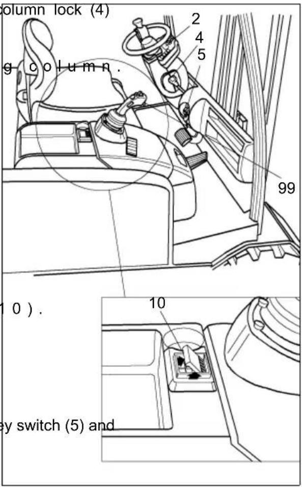
- Unlock the isolator (10).
- Push in the rocker (↓) and pull it up (↑) until you feel the isolator engaging (○) on trucks with multifunction armrest unlock the EMERGENCY DISCONNECT (22).
- Insert the key in the key turn it clockwise as far as it will go to the "I" position.
- Test the horn (99)..

Test the electric, hydraulic and parking brakes.
text_image
g column. column lock (4) g column. 99 10). 10 ey switch (5) and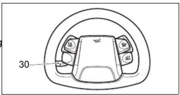
text_image
30
- The truck is now open information and service display (2) / control panel (21) shows the available battery capacity.
When you have applied the EMERGENCY DISCONNECT and turned the key switch to the right, the truck carries out a self test for approx. 3-4 seconds (tests the controllers and motors). During this time the truck cannot move. If the accelerator pedal is applied during this time, the display will show "Zero drive sens".
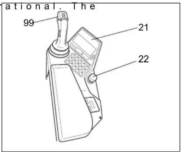
text_image
ational. The 99 21 223.8 Trucks with Heating (○)

Covering the heater is prohibited due to severe risk of burning.
- Set switch (100) to level or ll to switch on the heating column.

If the switch (100) is set to the middle position, the heating is off.
- Set switch 101 to level or ll to switch the fan on.

The fan must be on in heating mode.
- Set the desired temperature on the rotary button (102).
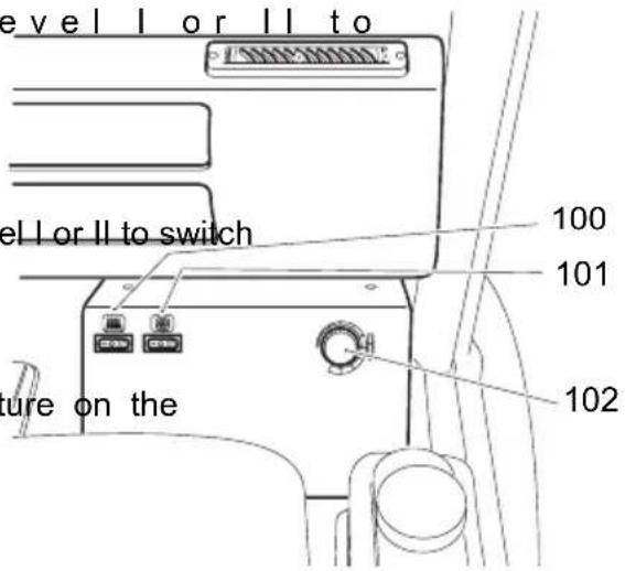
text_image
Level I or II to Level I or II to switch 100 101 102 Figure on the4.1 Safety regulations for truck operation
Travel routes and work areas: Only use lanes and routes specifically designated for truck traffic. Unauthorised third parties must stay away from work areas. Loads must only be stored in places specially designated for this purpose.
Driving conduct: The driver must adapt the travel speed to local conditions. The truck must be driven at slow speed when negotiating bends or narrow passageways, when passing through swing doors and at blind spots. The driver must always observe an adequate braking distance between the forklift truck and the vehicle in front and must be in control of the truck at all times. Abrupt stopping (except in emergencies), rapid U turns and overtaking at dangerous or blind spots are not permitted. It is forbidden to lean out of or reach beyond the working and operating area.
Travel visibility: The driver must look in the direction of travel and must always have a clear view of the route ahead. When carrying loads which affect visibility, these must be stored at the rear of the truck. If this is not possible, a second person must walk in front of the truck as a lookout.
Negotiating slopes and inclines: Negotiating slopes or inclines is only permitted if such roads are clean and have a non-slip surface and providing such journeys are safely undertaken in accordance with the technical specifications for the truck in question. The truck must always be driven with the load unit facing uphill. The industrial truck must not be turned, operated at an angle or parked on inclines or slopes. Inclines must only be negotiated at slow speed, with the driver ready to brake at any moment.
Negotiating lifts and docks: Lifts and docks must only be used if they have sufficient capacity, are suitable for driving on and authorised for truck traffic by the owner. The driver must satisfy himself of the above before entering these areas. The truck must enter lifts with the load in front and must take up a position which does not allow it to come into contact with the walls of the lift shaft. People travelling in the lift with the forklift truck must only enter the lift after the truck has come to a halt and must exit the lift before the truck.
Type of loads to be carried: The operator must make sure that the load is in a satisfactory condition. Do not carry loads unless they are positioned safely and carefully. Use suitable precautions, e.g. a load guard, to prevent parts of the load from tipping or falling down.
Towing trailers or the truck itself being towed are only permitted occasionally, on secure, level routes, with a maximum deviation of +/- 1% and at a max. speed of 5 km/h. Do not permanently operate the truck with trailers.
When the truck is pulling there must be no load on the forks.
Do not exceed the maximum trailer load specified for the forklift truck for trailers with or without brakes. The specified trailer load only applies for the auxiliary coupling in the counterbalance of the forklift. If a different trailer coupling is used on the truck, the instructions of the coupling manufacturer must be observed..
After coupling and before starting the driver must ensure that the trailer coupling cannot become detached.
Trucks pulling a load must be operated in such a manner that the trailing vehicle is driven safely and can be stopped at all times.
4.2 Travel

Travelling in electromagnetic fields beyond the permitted limits can result in random truck motion.
Immediately apply the EMERGENCY DISCONNECT, brake with the service brake and apply the parking brake.
Determine the cause of the fault and if necessary inform the manufacturer's service department.
Safety functions

If the driver's seat is not occupied (safety belt ○) not closed) or if the driver's weight is set too high, travel is interrupted by the safety switch (see Section 3 "Setting the Driver's Weight"). Occupying the driver's seat and applying the accelerator pedal releases the spring-loaded brake.
The travel speed reduces as a function of the steering angle. However, the driver is still responsible for adapting the travel speed to the conditions of the travel route, the work area and the load.

Do not drive the truck unless the panels are closed and properly locked.
Travel routes must be free of obstacles.
- Raise the fork carriag 200 mm so that the fork tines are clear of the ground.
-Tilt the mast fully ba
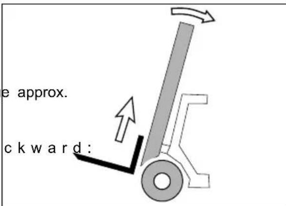
text_image
e approx. ckward:
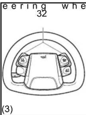
Depending on the truck model, the travel direction switch (103/14/32) can be fitted to the
-MULTI-PILOT Fig. (1)
-the SOLO-PILOT Fig.
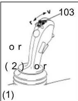
text_image
103 or (2) or (1)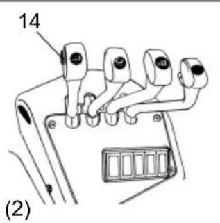
text_image
14 (2)- the multifunction st Fig. (3) or
-the fingertip Fig. (4)
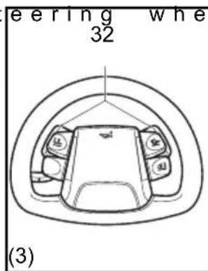
text_image
eering whe 32 (3)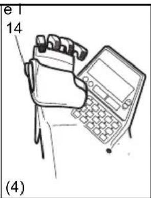
text_image
e1 14 (4)
There is no travel direction switch on trucks with a twin pedal.
Forward travel (single pedal)

Make sure that the travel area is clear.
- Release the parking
- Push the travel direct 14 / 32) on the MULTI-PILOT / SOLO-PILOT /multifunction steering wheel forward
-Slowly apply the acce
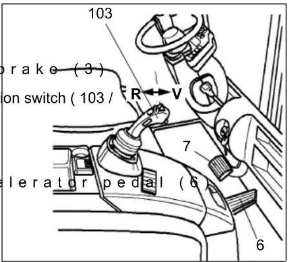
text_image
103 brake (3) on switch (103 / R V 7 elerator pedal (6) 6Forward travel (twin pedal)

Make sure that the travel area is clear
- Release the parking
- Slowly apply the acce (13)

Do not move the MULTI-PILOT to travel.
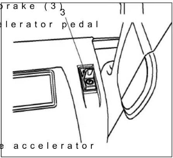
text_image
brake (3) 3 elerator pedal acceleratorChanging direction (single pedal)

Before setting off in the opposite direction, make sure that the reverse travel area is clear.
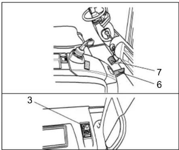
- Take your foot off the pedal (6).
- Applying the brake pedal (7), bring the truck to a halt.
- Push/pull the travel direction switch (103 / 14 / 32) back.
- Slowly apply the accelerator pedal until you reach the required travel speed.
Changing direction (twin pedal)

Before setting off in the opposite direction, make sure that the reverse travel area is clear.
- Take your foot off the pedal (13).
- Applying the brake pe the truck to a halt.
- Slowly apply the acce (11) until you reach the required travel speed.
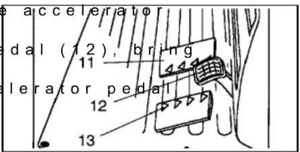
text_image
accelerator edal (12), bring elerator pedal 11 12 13Accelerating (single pedal)
- Slowly apply the accelerator pedal (6) until the truck starts to move. 103
- Continue to depress (6).
The motor speed and travel speed increase the more you apply the accelerator.
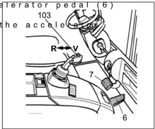
text_image
elerator pedal (6) 103 the accelerator R←V 7 6Accelerating (twin pedal)
- Slowly press the acce or 13) depending on the direction selected, until the truck starts to move.
- Continue to depress the accelerator pedal (11/13). The motor speed and travel speed increase the more you apply the accelerator.
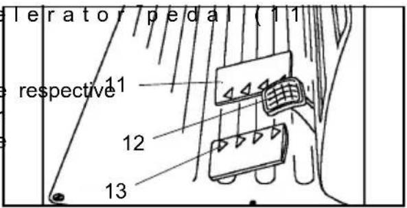
text_image
levator pedal (11 respective 11 12 13Braking

The braking pattern depends largely on the ground conditions. The driver must take this into consideration when handling the truck. Brake with care to prevent the load from slipping.
If you are travelling with an attached load you must increase the braking distance.
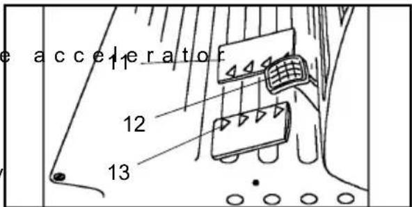
- Take your foot off the accelerator pedal (6) (11/13) and if necessary gently apply the brake pedal (7/12) (see also Section 4.4).
4.3 Steering

Very minimal steering effort is required for the electric steering, therefore turn the steering wheel sensitively.
Negotiating right hand bends
- Turn the steering wheel clockwise to match the desired steering radius.
Negotiating left hand bends
- Turn the steering wheel anti-clockwise to match the desired steering radius.
4.4 Braking
There are four ways of braking:
- Service brake
- Coasting brake
- Reversing brake
- Parking brake
- Spring-loaded brake
Service brake:
- Depress the brake pedal (7/12) until you feel the brake pressure.

The service brake acts on the drive wheels via the multi-plates.
text_image
Technical diagram showing car interior components with numbered labels pointing to different parts of the dashboard.Coasting brake:
- Take your foot off the pedal (6) (11/13). The truck brakes regeneratively via the traction controller.

This operating method reduces energy consumption.
text_image
accelerator 12 13Reversing brake (single pedal)
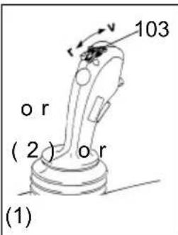
- Set the travel direction switch (103/14/32) to the opposite direction while travelling. The truck brakes regeneratively via the traction controller until it starts to travel in the opposite direction.

Depending on the truck model, the travel direction switch (103/14/32) can be fitted to the
-MULTI-PILOT Fig. (1)
-the SOLO-PILOT Fig.
text_image
103 or (2) or (1)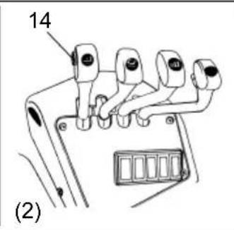
text_image
14 (2)- the multifunction st Fig. (3) or
-the fingertip Fig. (4)

There is no travel direction switch on trucks with a twin pedal.
text_image
eering whe 32 (3)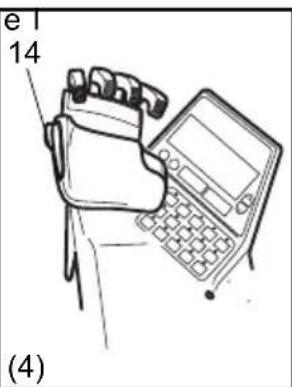
text_image
e 14 (4)Reversing brake (twin pedal)
During travel, depress the accelerator pedal (11/13) for the opposite direction. The truck brakes regeneratively via the traction controller until it starts to travel in the opposite direction.
Parking brake:
- Apply the parking brake

The parking brake actuates a black and white valve, braking cannot be performed with any degree of sensitivity.

The parking brake acts mechanically on the drive wheels via the multi-plates.

The parking brake will keep the truck with the maximum permissible load, on a clean ground surface, on a 15 % incline.
Spring-loaded brake
The spring-loaded brake applies approx. 30 seconds (adjustable) after the truck comes to a halt, and approx. 1 to 5 seconds (adjustable) after the driver's seat has been vacated.
When you stop on the ramp the truck is held electrically until the spring-loaded brake applies.
When you set off, before the spring-loaded brake is released, a torque builds up on the drive motor to prevent the truck from rolling back.
4.5 Operating the lift mechanism and attachments (MULTI-PILOT)

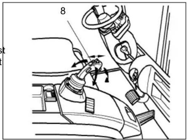
The Multipilot must only be operated from the driver's seat. The driver must be instructed in how to handle the lift mechanism and the attachments.
Push the Multipilot in the desired direction, depending on the hydraulic function.
text_image
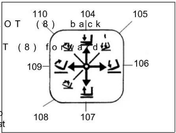
8Lifting/ lowering the fork carriage
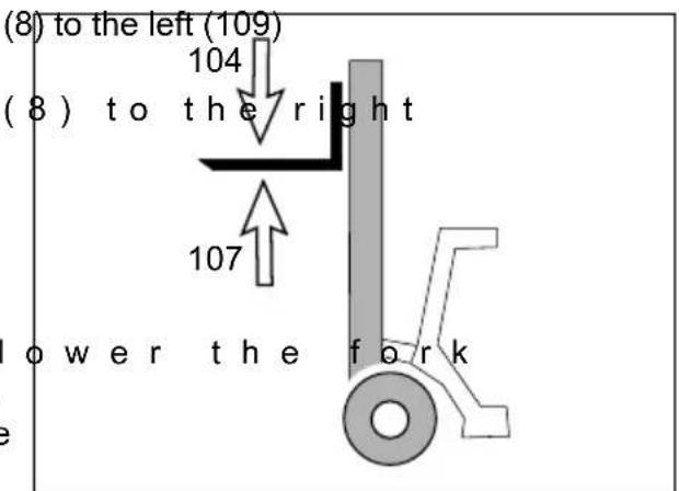
- Move the MULTI-PIL (107) to raise the fork carriage.
- Move the MULTI-PILO (104) to lower the fork carriage.
Tilting the mast forward / backward

When tilting the mast back, ensure no part of your body is between the mast and the front panel.
text_image
110 OT (8) 104 back 105 T (8) for w a d 109 106 108 107- Move the Multipilot to tilt the fork carriage back.
- Move the Multipilot (106) to tilt the fork carriage forward.
Twin operation
- To simultaneously I carriage and tilt the mast forward, move the Multipilot forward and to the right (105).
- To simultaneously raise the fork carriage and tilt the mast back, move the MULTI-PILOT back and to the left (108).
- To simultaneously raise the fork carriage and tilt the mast back, move the MULTI-PILOT forward and to the left (110).
text_image
(8) to the left (109) 104 (8) to the right 107 lower the fork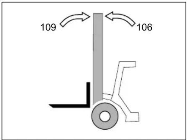
text_image
109 1064.5.1 Controlling Attachments (Multipilot) (○)

Note the manufacturer's operating instructions and the capacity of the attachment. Do not lift other people with the lifting device.
Auxiliary Controller I (Integrated Sideshift)
- Press the button (1110) on the Multipilot to push the fork carriage to the left.
- Press the button (1) Multipilot to push the fork carriage to the right.
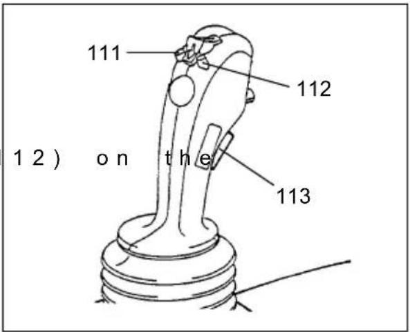
text_image
111 112 12) on the 113Auxiliary Controller II

The MULTI-PILOT can be turned to activate a hydraulic attachment. Read the manufacturer's operating instructions when operating attachments.
Auxiliary Controller III
For auxiliary controller III press the key (113) on the MULTI-PILOT (e.g. locking).
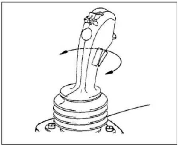
natural_image
Line drawing of a mechanical lever mechanism with rotational arrows indicating motion (no text or symbols)Controlling the speed of the lifting device
You control the hydraulic cylinder speed by moving the MULTI-PILOT.
When the MULTI-PILOT is released it automatically reverts to neutral and the lifting device remains in the position it has reached.

Always apply the MULTI-PILOT sensitively, never with a sudden jerk. Release the Multipilot as soon as the lifting device reaches its limit position.
4.6 Operating the lift mechanism and attachments (SOLO-PILOT)

The SOLO-PILOT must only be operated from the driver's seat. The driver must be instructed in how to operate the lifting unit and the attachments.
Lifting/ lowering the fork carriage
- Pull the SOLO-PILOT raise the fork carriage.
- Press the SOLO PILO front to lower the fork carriage.
Titing the mast forward / backward

When tilting the mast back, ensure no part of your body is between the mast and the front panel.
- Pull the SOLO-PILOT the mast back.
- Push the SOL-PILOT (17) forward to tilt the mast forward.
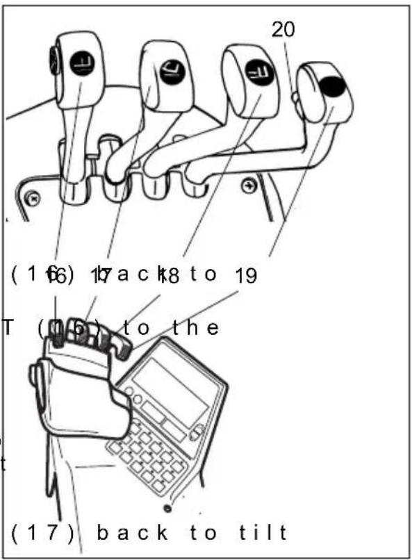
text_image
(1 66) 17 ack to 19 T (105) to the (17) back to tilt4.6.1 Controlling Attachments (SOLO-PILOT) (○)

Note the manufacturer's operating instructions and the capacity of the attachment. Do not lift other people with the lifting device.
- Pull the auxiliary hydraulics control lever ZH1 (18) backwards or push it forward to control the attachment (e.g. sideshift).
- Pull the auxiliary hydraulics control lever ZH2 (19) backwards or push it forward to control the attachment (e.g. fork positioner).
- You can use button (20) to toggle the ZH2 control lever (19) to auxiliary hydraulics ZH3.
The auxiliary hydraulics ZH3 can only be activated when the button (20) is pressed and the control lever is in the neutral position. To control the attachment, pull the SOLO-PILOT ZH2 lever (19) back or push it forward. The auxiliary hydraulics ZH3 are deactivated when the button (20) is released and the control lever has returned to the neutral position.
Moving the lever controls the lift speed of the hydraulic cylinder.
When the lever is released it automatically reverts to neutral and the lifting device remains in the position it has reached.

Always apply the control lever sensitively, never with a sudden jerk. Release the control lever as soon as the lifting device reaches the limit position.
Integrated Sideshift (○)
The fork carriage can be moved sideways using the integrated sideshift.
- Pull the auxiliary hydraulics control lever ZH1 (18) back = sideshift right.
- Push the auxiliary hydraulics control lever ZH1 (18) forward = sideshift left.
Integrated fork positioner (○)
The integrated fork positioner allows the distance between the forks to be set.
- Pull the auxiliary hydraulics control lever ZH2 (19) back = forks together.
- Push the auxiliary hydraulics control lever ZH2 (19) forward = forks apart.

The fork positioner can be synchronised to ensure the forks are even. The forks must be spread apart as far as the stop and then brought back together.
Other Attachments
Additional equipment can only be attached with written permission from the manufacturer, see chapter A “Attaching Accessories”. Always follow the manufacturer’s operating instructions when using other attachments.
The control levers of the attachments must be indicated by symbols to illustrate the function of the attachment.

Only use attachments that have CE approval. The reduced residual capacity must be re-calculated and indicated by a separate capacity plate.
4.7 Operating the lift mechanism and attachments (multifunction steering wheel)

The multifunction steering wheel must only be operated from the driver's seat. The driver must be instructed in how to operate the lifting unit and the attachments.
Lifting/ lowering the fork carriage
- Pull the button (28) to carriage.
- Push the button (28) to carriage.
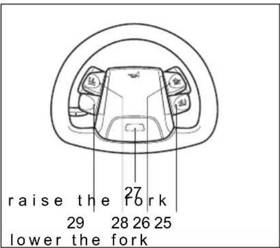
text_image
raise the fork 29 28 26 25 lower the forkTilting the mast forward / backward

When tilting the mast back, ensure no part of your body is between the mast and the front panel.
- Pull the button (26) to tilt the mast back. - Push the button (26) to tilt the mast forward.
Controlling attachments

Note the manufacturer's operating instructions and the capacity of the attachment. Do not lift other people with the lifting device.
- Pull or push the auxiliary hydraulics button ZH1 (29) to control the attachment (e.g. sideshift).
- Pull or push the auxiliary hydraulics button ZH2 (25) to control the attachment (e.g. fork positioner).
- You can use the toggle switch (27) to toggle from auxiliary hydraulics ZH1 (29) to the auxiliary hydraulics ZH3. When the auxiliary hydraulics ZH3 are activated, an LED on the toggle switch (27) lights up. Pull or push the auxiliary hydraulics button (29) to control the attachment. When the toggle switch (27) is pressed again the auxiliary hydraulics ZH3 are deactivated.
The distance moved by the button controls the lift speed of the hydraulic cylinder. When the button is released it automatically reverts to neutral and the lifting mechanism remains in the position it has reached.

Apply the buttons sensitively and avoid sudden movements. Release the button as soon as the lifting mechanism reaches the limit position.
4.8 Collecting, transporting and depositing loads

Before lifting a load, the driver must ensure that it is correctly palletised and that the capacity of the truck is not exceeded.
Note the load chart.
Adjusting the forks

Adjust the forks in such a way that both are equally distanced from the outer edge of the fork carriage and the load centre of gravity lies in the middle of the forks.
-Raise the locking lev
- Push the forks (114) position on the fork carriage (116).
- Turn the locking leve the fork time until it engages in a slot.
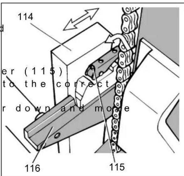
text_image
114 er (1 15) to the correct r down and move 116 115Lifting a load
- Carefully approach the load to be lifted.
- Apply the parking brake (3).
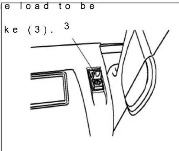
text_image
e load to be ke (3). 3- Set the mast vertical - Raise the forks to the the load.
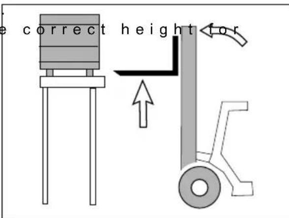
text_image
e correct height for
- Drive the truck with forks spread as far apart as possible underneath the load.
At least two thirds of their length must extend into the load.
- Apply the parking bra fork carriage until the load rests freely on the forks.
- Set the travel directi reverse and release the parking brake.
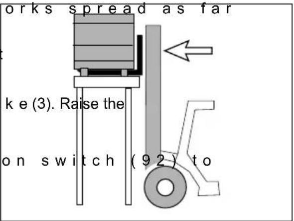
text_image
orks spread as far ke (3). Raise the on switch (92) to
Make sure you have enough space to reverse into.
- Reverse carefully and load is outside the storage area.

xDo not stand underneath a raised load. Do not reach through the mast.
- Tilt the mast fully ba - Lower the load as far necessary for transport (ground clearance approx. 150...200mm).
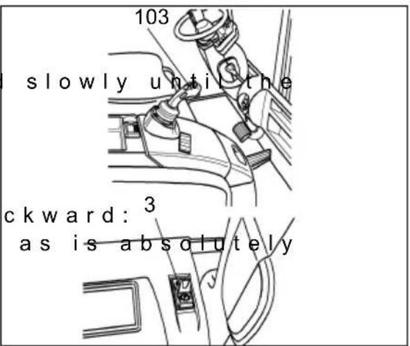
text_image
103 slowly until the ckward: ³ as is absolutely
When transporting loads, the mast must be tilted back and the forks lowered as far as possible.
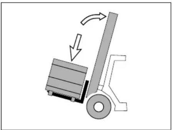
natural_image
Diagram of a forklift lifting a truck, showing motion direction (no text or symbols)Transporting a load
STOP
If the load is stacked so high that it affects forward visibility, then reverse.
- Gently accelerate with pedal (6) and slowly brake with the brake pedal (7). Be ready to brake at all times.
- Adapt your travel conditions of the route and the load you are transporting.
- Watch out for other tr and passageways.
- Always travel with blindspots.
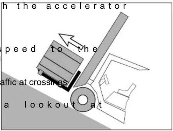
text_image
h the accelerator speed to the affic at crossings a lookout atSTOP
On slopes and inclines always carry the load facing uphill, never approach at an angle or turn.
Depositing a load
- Drive the truck carefully up to the load handler.
- Apply the parking bra
- Set the mast vertical
- Raise the forks to the load handler.
- Release the parking brake.
- Carefully enter the load handler.
- Slowly lower the load are free.
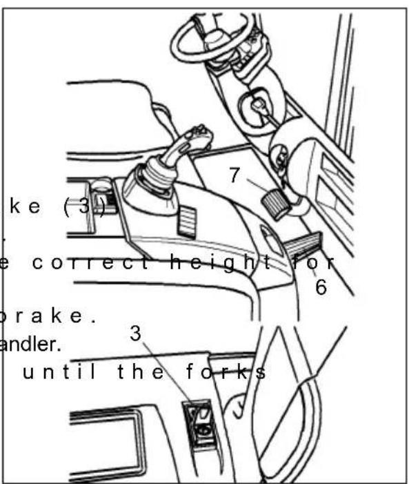
text_image
ake (3) e correct height for brake. andler. until the forks!
Avoid depositing the load suddenly to avoid damaging the load and the load handler.
STOP
You can only tilt forward when the load handler is raised in front of or above the stack.
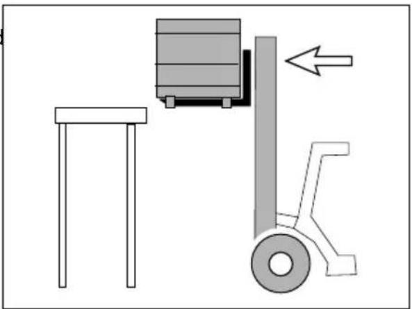
natural_image
Diagram showing a forklift lifting a table and a load, with no text or symbols present.4.9 Parking the truck securely

When you leave the truck it must be securely parked even if you only intend to leave it for a short time.
-Drive the truck onto a level surface.
- Apply the parking brake (3).
-Fully lower the load forks and tilt the mast forward.

Never park and abandon a truck with a raised load.
- Press the isolator (10)
- Turn the key in the key switch (5) to "0".
- Remove the key from the key switch (5).
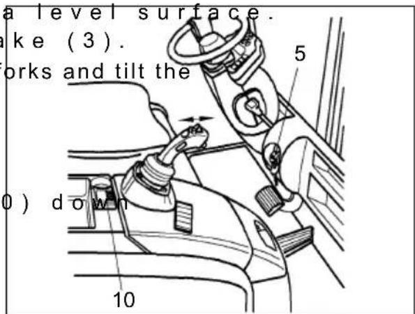
text_image
a level surface. ake (3). orks and tilt the 0) down 10 5
Avoid parking the truck in areas below 15^ C, as this will render the hydraulic fluids extremely viscous and consequently the hydraulic functions harder to operate.
Never operate a cold pump at full speed. Heat up the oil by repeatedly tilting and/or lifting slowly.
The LCD display may fail temporarily. As the temperature rises the display will appear again.
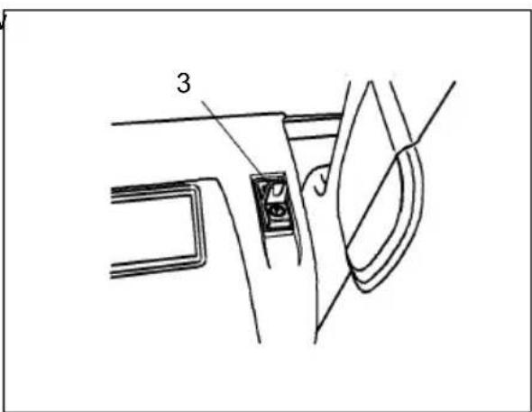
text_image
34.10 Towing trailers
The truck can occasionally be used to tow a light trailer on a dry, level and well maintained surface.

The max. tow load is the capacity indicated on the capacity data plate (see decals diagram in chapter B).
The tow load consists of the weight of the trailer and the stated capacity.
If a load is transported on the forks, the tow load must be reduced by the same amount.

Important notes for safe towing
– A truck must not be continually operated with trailers.
- No supporting loads are permitted.
– The maximum speed is 5 km/h.
- Towing must only be performed on level, secure travel routes.
- Follow the instructions of the coupling manufacturer if using special trailer couplings.
- The owner must test trailer operation with the permissible tow load by means of a trial run under the applicable operating conditions in the field.
Attaching the trailer
- Push the tow pin (117 it 90 degrees.
- Pull the tow pin up of the trailer vehicle into the opening.
- Insert the tow pin, push it down, turn it 90 degrees and engage it.
4.11 Tow loads

Before coupling, the driver must ensure the maximum trailer load is not exceeded.
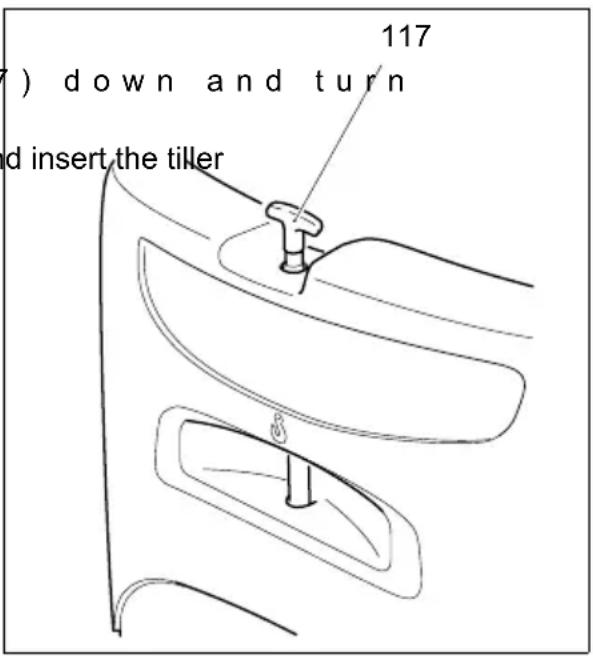
text_image
7) down and turn d insert the tiller 117This chapter is designed to help the user identify and rectify basic faults or the results of incorrect operation. When locating a fault, proceed in the order shown in the table.
| Fault Probable Cause Action | ||
| Truck does not travel. | - Battery conot plugged in- Main switch pressed.- Key switch in “0” position-Battery charge too low-Faulty fuse | - Check the battery connec necessary.- Release isolator- Set key switch to “l”- Check battery charge, charge necessary- Check fuses |
| Load cannot be lifted | - Truck not operational- Hydraulic too low-Faulty fuse-Battery ch low | - Carry out all measures listed does not travel"- Check the hydraulic oil level- Check fuses- Check battery charge, charge necessary |
| Error message displayed | - Truck not operational- Software fa | - Press EMERGENCY DISCON isolator or turn key switch to 0, after approx. 31 seconds try to perform the desired operation again |

If the fault cannot be rectified after carrying out the remedial procedure, notify the manufacturer's service department, as any further troubleshooting can only be performed by specially trained and qualified service personnel.
F Maintenance of
The checks and servicing operations contained in this chapter must be performed in accordance with the intervals as indicated in the servicing checklists.

Modifications of fork lift truck assemblies, especially of the safety installations, are not permitted. On no account must the operational speeds of the truck be changed.

Only original spare parts have been certified by our quality assurance service. To ensure safe and reliable operation of the fork lift truck, only spare parts of the manufacturer must be used. Used parts, oils and fuels must be disposed of in accordance with the applicable environmental protection regulations. For oil changes, the oil service of the manufacturer is available to you.
Upon completion of any checking and servicing activities, the operations contained in the section “Recommissioning” must be performed (refer to chapter F).
2 S a f e t y r e g u l a t
Servicing and maintenance personnel: The fork lift truck must only be serviced and maintained by trained personnel of the manufacturer. The service organization of the manufacturer has external technicians trained especially for these assignments. We thus recommend signing a maintenance contract with the relevant service location of the manufacturer.
Lifting and jacking up: When a fork lift truck is to be lifted, the lifting gear must only be secured to the points specially provided for this purpose. When the truck is to be jacked up, suitable measures must be taken to prevent the truck from slipping or tipping over (use of wedges, wooden blocks). Work underneath the raised load lifting device must only be carried out when the fork is immobilised and supported by a chain of adequate strength.

Jacking point see chapter B.
When work has to be performed under the raised fork or under the jacked up truck, suitable measures must be taken to prevent any dropping, tilting or slipping of the fork or truck. When lifting the truck, the instructions contained in chapter “Transportation and commissioning” have to be observed.
When performing work on the parking brake, the truck must be secured against moving.
Cleaning operations: No inflammable liquids must be used when cleaning the fork lift truck. Prior to commencing cleaning operations, all safety measures that are required to prevent sparking (e.g. by short-circuits) have to be taken. For battery-operated fork lift trucks, the battery plug must be removed. Only weak indraft, weak compressed air and non-conducting, antistatic brushes must be used for the cleaning of electric or electronic assemblies.

If the fork lift truck is to be cleaned using a water jet or a high-pressure cleaner, all electric and electronic components must be carefully covered beforehand because moisture can lead to incorrect functioning.
Cleaning by means of a steam jet is not permitted.
Upon completion of cleaning work, the operations detailed in the section "Recommissioning" must be performed.
Work on the electric system: Work on the electric system of the truck must only be performed by personnel specially trained for such operations. Before commencing any work on the electric system, all measures required to prevent electric shocks have to be taken. For battery-operated fork lift trucks, the truck must also be depowered by removing the battery plug.
Welding operations: To prevent any damage to electric or electronic components, these have to be removed from the fork lift truck before any welding operations are undertaken.
Settings: When repairing or replacing hydraulic, electric or electronic components or assemblies, all truck-specific settings have to be retained.
Wheels: The quality of wheels affects the stability and performance of the truck. When replacing wheels fitted at the factory, only use manufacturer's original spare parts. Otherwise the truck's rated performance cannot be ensured.
When replacing wheels, ensure that the truck does not slew (e.g. always replace wheels in pairs, i.e. left and right wheels at the same time).
Lift chains: The lift chains wear rapidly if not lubricated. The intervals in the service checklist apply to normal duty. If requirements are higher (dust, temperature), lubrication is required more often. The specified chain spray must be used as specified. The external application of grease does not provide sufficient lubrication.
The chain tensioners must be adjusted in such a manner that they can adapt themselves to the pulling direction of the chain. Pretensioning the tensioner head against the mounting is not allowed. A minimum distance of 20 mm must be kept.
Hydraulic hoses: The hoses must be renewed every six years. When replacing hydraulic components, also renew the hoses in this hydraulic system.
3 Servicing and inspection
Thorough and expert servicing is one of the most important preconditions for safe operation of the forklift truck. Failure to perform regular servicing can lead to truck failure and poses a potential hazard to personnel and equipment.

The application conditions of an industrial truck have a considerable impact on the wear of the service components.
We recommend that a Jungheinrich customer service adviser carries out an application analysis on site to work out specific service intervals to prevent damage due to wear.
The service intervals listed are based on single shift operation under normal operating conditions. They must be reduced accordingly if the truck is to be used in conditions where there is heavy dust, temperature fluctuations or multiple shifts.
The following maintenance check list gives the tasks and times at which they should be carried out. Maintenance intervals are defined as:
W = Every 50 service hours or at least weekly
A = E v e r y 5 0 0 s e r v i c e h o u
B = Every 1000 service hours, or at least six months
C = Every 2000 service hours, or at least annually

W service intervals are to be performed by the customer.
In the run-in period - after approx. 100 service hours - or after repair work, the owner must check the wheel nuts/bolts and re-tighten if necessary.
| Maintenance intervals | ||||||
| Standard = ●W A | B | C | ||||
| Chassis/ Superstructure | 1.1 Check all load bearing components for damage ● | |||||
| 1.2 Check screw connections ● | ||||||
| 1.3 Check trailer coupling ● | ||||||
| 1.4 Check overhead guard for damage and make sure it is secure | ||||||
| 1.5 Test seat belt operation and check for damage ● | ||||||
| 1.6 Test restraint system (option) operation and check for damage | ||||||
| 1.7 Check overhead guard for damage and make sure it is secure | ||||||
| Drive: | 2.1 Check transmission for noise and leakage | ● | ||||
| 2.2 Check transmission oil level | ● | |||||
| 2.3 Check pedal mechanism, adjust and lubricate if necessary | ● | |||||
| 2.4 Change transmission oil | ● | |||||
| Wheels: | 3.1 Check wheels for wear and damage | |||||
| 3.2 Check air pressure | ||||||
| 3.3 Check suspension and attachment | ● | |||||
| 3.4 Replace wheel bearing grease fillings for front and rear wheels and re-adjust the wheel bearings. | ● | |||||
| Steering: | 4.1 Test operation of hydraulic components and check for leaks | ● | ||||
| 4.2 At the latest after 500 hours lubricate all bearings points on the steering axle (wheel bearings, steering knuckle pins, steering lever) in accordance with the lubrication schedule using a trade standard grease gun. | ||||||
| 4.3 Check steering axle, axle knuckle and stops for wear and deformation | ||||||
| 4.4 Clean the steering angle sensor with compressed air | ● | |||||
| Brake system: | 5.1 Test operation and settings | ● | ||||
| 5.2 Check brake mechanism, adjust and lubricate if necessary | ● | |||||
| 5.3 Check brake lines, connections and oil level for the brake system | ● | |||||
| 5.4 Replace brake system mineral oil | ● | |||||
| 5.5 Measure the holding force of the spring-loaded brake | ● | |||||
| 5.6 Check the brake oil level (mineral oil) | ||||||
| Hydr. system: | 6.1 Check connections for leaks and damage | ● | ||||
| 6.2 Check ventilation and aeration filter at hydraulics tank | ● | |||||
| 6.3 Check oil level | ● | |||||
| 6.4 Check hydraulic cylinders for leaks, damage, and secure attachment | ● | |||||
| 6.5 Check hose line for correct function and damage | ● | |||||
| 6.6 Change filter cartridge (hydraulic oil and aeration filter) | ● | |||||
| 6.7 Change hydraulic oil | ||||||
| 6.8 Check pressure relief valves for correct function | ||||||
| 6.9 Change vacuum filter (steering) | ● | |||||
| Electr. system: | 7.1 Check function of instruments and indicators ● | |||||
| 7.2 Check cables for secure connection and damage ● | ||||||
| 7.3 Check cable guides for function and damage ● | ||||||
| 7.4 Check the warning devices and safety circuits for correct function | ● | |||||
| 7.5 Check contactor ● | ||||||
| 7.6 Check fuses for correct amperage ● | ||||||
| 7.7 Clean installation space of electronics and cooling fins | ● | |||||
| 7.8 Read out and clear error memory ● | ||||||
| Electric motors: | 8.1 Check the motor for secure attachment ● | |||||
| 8.2 Check fan for correct function ● | ||||||
| 8.3 Clean motor cooling fins | ● | |||||
| Battery: | 9.1 Check battery cables for damage and replace, if necessary | ● | ||||
| 9.2 Check acid density, acid level, and cell voltage | ● | |||||
| 9.3 Check terminals for secure attachment and apply grease | ● | |||||
| 9.4 Clean battery plug connections, check for tight seat | ● | |||||
| Mast: | 10.1 Apply grease to the tracks and the side contact surface of the guide rollers in the mast sections. | ● | ||||
| 10.2 Check lift chains for wear and adjust. | ● | |||||
| 10.3 Lubricate lift chains and check tension. | ● | |||||
| 10.4 Check mast attachment | ● | |||||
| 10.5 Check tilt cylinder suspension and attachment | ● | |||||
| 10.6 Check forks and fork carriage for wear and damage | ● | |||||
| 10.7 Visually inspect rollers, slide pieces and stops | ● | |||||
| 10.8 Test mast tilt angle.Make sure both tilt cylinders extend evenly. | ● | |||||
| 10.9 Check mast play and if necessary adjust lateral play using spacers. | ● | |||||
| General Measurements: | 11.1 Test electrical system for frame leakage in accordance with VDI 2511 | ● | ||||
| 11.2 Test travel speed and braking distance | ● | |||||
| 11.3 Test lift and lowering speeds | ● | |||||
| Demonstration | 12.1 Test run with rated load | ● | ||||
| 12.2 After carrying out maintenance, present the truck to the supervisor. | ● | |||||
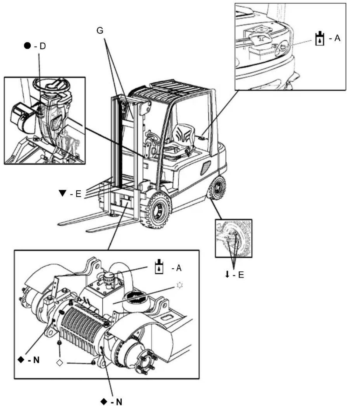
text_image
Technical diagram of a forklift assembly with labeled components and directional indicators (A, E, D)▼ Glide surfaces
◆ Transmission oil filler pipe
↓Lubricator nipple ◇Transmission oil drain plug

Hydraulic oil filler pipe ●
Filler pipe for brake system mineral oil
Hydraulic oil drain plug
5.1 Fuels, coolants and lubricants
Handling consumption type material: Consumption type material must always be handled properly. Manufacturer's instructions to be observed.

Improper handling is injurious to health, life, and environment. Consumption type materials must be stored in adequate containers. They might be inflammable and, therefore, must not come into contact with hot components or open fire.
When filling in consumption type materials use clean containers only. It is prohibited to mix consumption type materials of different grades or qualities resp., except if mixing is expressively prescribed in these operating instructions.
Avoid spilling. Spilt liquid must be removed immediately using a suitable binding agent, and the mixture of consumption type material and binding agent is to be disposed of according to the regulations.
| Code | Order-no. | Quantity Designation | tion Used for | |
| A | 50426072 | HV 6834.5 I | Renolin 32^1) HLPD | Hydraulic system50429647 Renolin |
| ^2) HLPD | ||||
| 50124051 H | ^3) | |||
| 51082888 R | Plantosyn 46 H | VI(BIO hydraulic oil) | ||
| D | 50429647 | 0.25 l | Renolin 22 | Hydraulic brake system |
| E | 50055726 | Lubricating grease KP 2 K^3) | Front and rear wheel -wheel bearing | |
| G | 29201280 | Chain spray | Chains | |
| N | 50137755 | 2x approx. 3 l | Shell Donax TC 50 Universal | Transmission |

The trucks are filled at the factory with H-LPD 32 hydraulic oil or Plantosyn 46 HVI BIO hydraulic oil.
You cannot change from “Plantosyn 46 HVI” BIO hydraulic oil to H-LPD 32. The same applies to changing from H-LPD 32 hydraulic oil to Plantosyn 46 HVI BIO hydraulic oil. Furthermore you cannot mix H-LPD 32 hydraulic oil with Plantosyn 46 HVI BIO hydraulic oil.
Grease data
| Code | Saponification | Drop point °C | Worked penetraton at 25 °C | NLG1 class | Usage temperature °C |
| E | Lithium | 185 | 265-295 | 2 | -35/+120 |
1) valid for temperature -5/+30 °C
2) valid for temperature -20/-5 °C
3) valid for temperature +30/+50 °C
6.1 Prepare truck for the servicing and maintenance operations
All required safety measures must be taken to prevent any accidents in the course of the servicing and maintenance operations. The following preparatory operations must be performed:
- Expose the batteries (refer to chapter D).
6.2 Check attachment of tyres
- Park and lock the truther E).
- Crosswise tighten the with a torque wrench.
Torque
Wheels/Drive axle 6-hole Wheel rim M_A = 330 Nm
Wheels/Drive axle 10-hole Wheel rim M_A = 220 Nm
Wheels/Steering axle M_A = 170 Nm
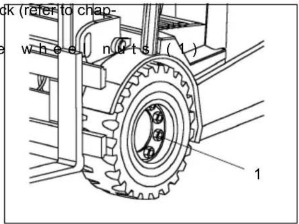
text_image
ck (refer to chap- wheel nuts (1) 16.3 Tyre pressure
Wheels/Drive axle 10 bar
Wheels/Steering axle 7 - 8 bar
6.4 Check hydraulic oil level

The load lifting device must be completely lowered.
- Prepare truck for the maintenance operations (refer to section 6.1).
- Unscrew air filter with
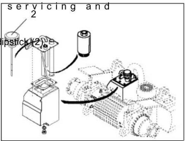
text_image
servicing and 2 lipstick (2)- Visually check hydra dipstick (3).

If the tank is sufficiently filled the hydraulic level must be readable at the upper marking (4).
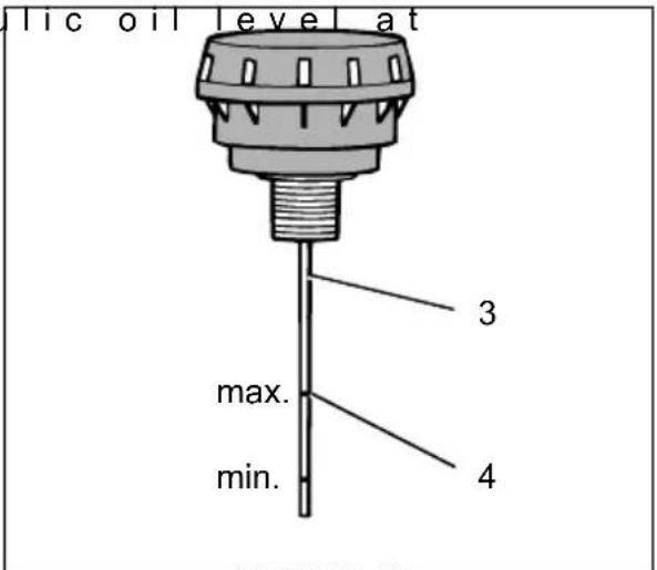
text_image
lic oil level at 3 max. min. 4- If required, refill hydraulic oil up to the required level (10 mm at dipstick (3) correspond to approximately 1 l hydraulic oil).

Do not overfill hydraulic tank above the upper marking, as this may result in malfunctions and damages of the system.
Used consumption-type materials must be disposed of in accordance with the applicable environmental protection regulations.

Trucks with bio hydraulic oil have a warning notice on the hydraulic reservoir: "Fill only with hydraulic oil". Use only bio hydraulic oil, see "Lubricants" section.
text_image
BIO6.5 Check transmission oil level

Transmission oil must not be spilt into the soil; therefore, place an oil pan under the transmission.
- Park and lock the truder E).
- Unscrew oil drain plu
- Check transmission o quired, refill transmission oil.

The filling level must reach to the lower edge of oil check hole (5a).

Do not refill transmission oil up to oil check hole (5).

Used consumption-type materials must be disposed of in accordance with the applicable environmental protection regulations.
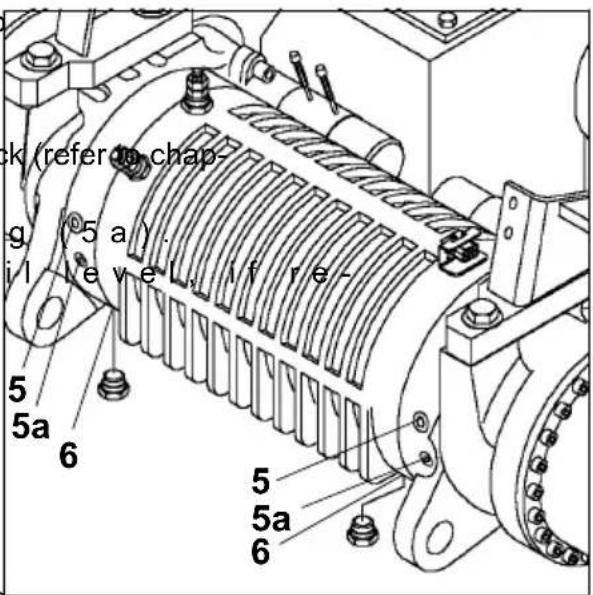
text_image
ck (refer chap- g (5 a) - i/1 level, if re- 5 5a 6 5 5a 66.6 Draining oil
- Drain the oil when the oil is at operating temperature.
- Place an oil pan under the unit.
- Unscrew oil drain plug (6) and drain transmission oil.
6.7 Refilling oil
- Renew sealing washer and screw in oil drain plug.
- Unscrew oil check screw.
- Refill new transmission oil with oil filling plug (5) removed up to the lower edge of oil check hole (5a).
6.8 Changing the hydraulic filter
The hydraulic filter is located to the left of the tilting cylinder and can be accessed after removing the bottom plate.
- Unscrew hydraulic fil
- Replace the filter cartr O-ring is damaged, the O-ring must also be replaced. Lightly oil the O-ring before installation.
-Screw in the cap agai
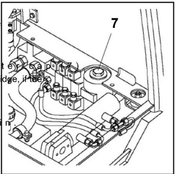
text_image
7 ter cap idge, if tbe in.6.9 Changing the vacuum filter
The vacuum filter (10) for the steering system is located in the hydraulic tank. Remove hydraulic tank cover and screw off vacuum filter.

text_image
Technical diagram showing a mechanical assembly with labeled components and a numbered component '10'6.10 Check oil level for brake system
The brake fluid tank can be seen from the right side when the steering column is tilted back.
To refill or change the mineral oil the cover (8) must be removed.
Do not use conventional brake fluid, refill only with prescribed mineral oil!
- Remove cover (8) after screws.
- Visually check the oil pansion tank (9) and refill transmission oil, if required (refer to section 5.1).
- Park and lock the truck (refer to chapter E).
The oil level must be visible between markings "Min" and "Max".
Used consumption-type materials must be disposed of in accordance with the applicable environmental protection regulations.
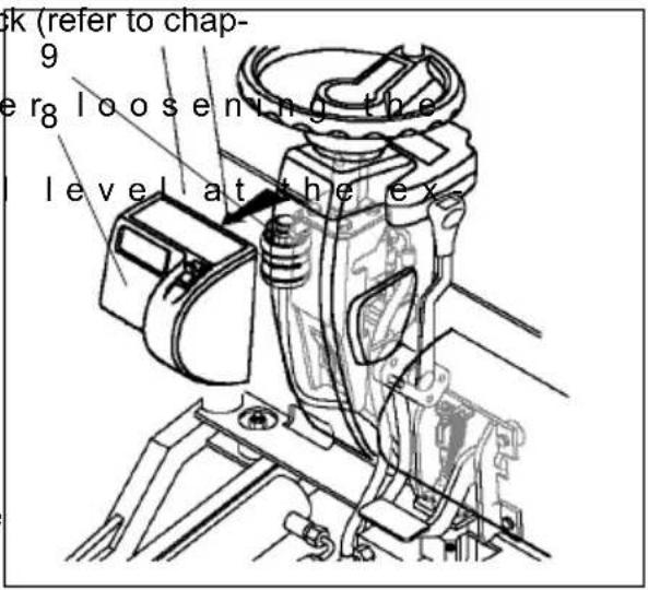
text_image
ck (refer to chap- 9 er8 loosening the level at the ex6.11 Restrain safety belt service
The driver must check condition and correct operation of the safety restraint belt on daily basis before using the industrial truck. Early detection of malfunctions is only possible through regular checks.
- Pull out belt completely and check for unravelling.
- Check the function of the belt buckle for correct retraction of the belt into the retractor
– Check cover for damage
Testing the automatic blocking retractor:
- Park the industrial truck on a horizontal surface
- Pull out the belt with a jerk

The automatic blocking system must lock the belt in the retractor.
- Open motor hood approximately 30 degrees

The automatic blocking system must lock the belt in the retractor

Do not operate the industrial truck when the safety restraint belt is defective; have the belt exchanged immediately!
6.12 Checking the electric fuses
- Prepare the truck for the servicing and maintenance operations (refer to section 6.1).
- Open the battery cover or unscrew the electronics cover.
- Unscrew the cap.
- Check the fuses according to the table for correct amperage and condition.

To avoid damages at the electrical system, only fuses with the appropriate ratings must be used.
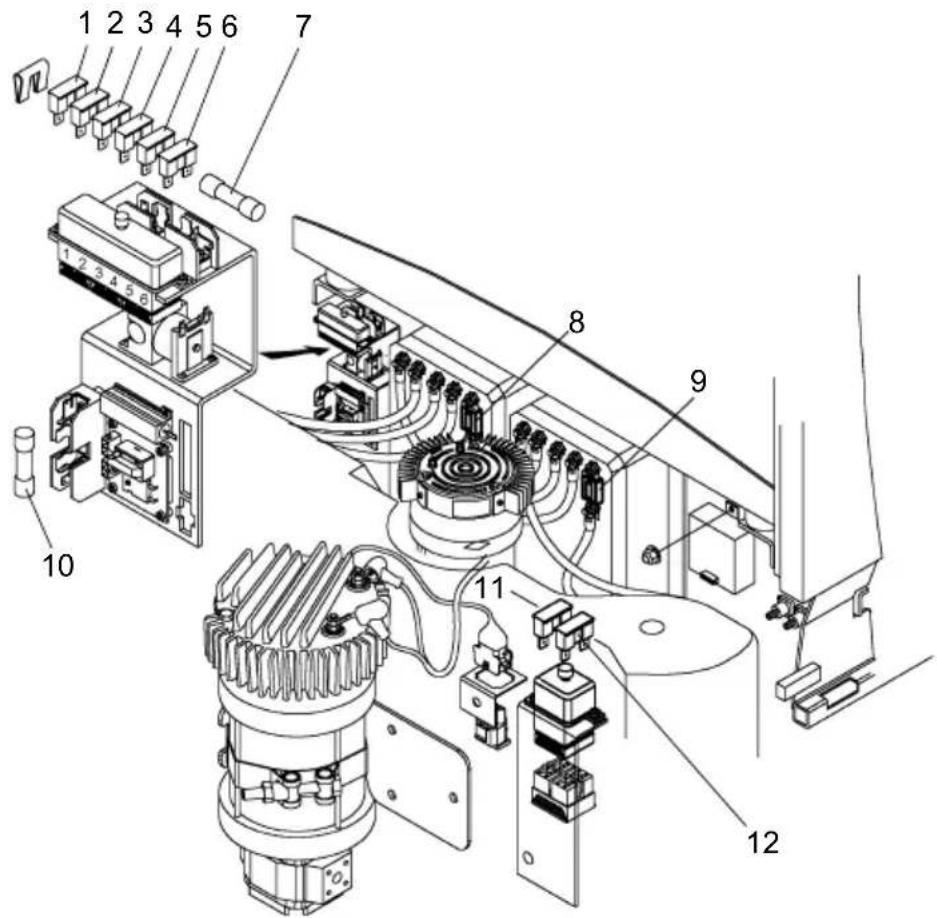
text_image
Technical diagram of an industrial electrical control unit with numbered components for identification| Item | Designation Electric circuit Rating / type | ||||
| 1 | O | p | t | ||
| 2 | F | 3 | . | 1 C | o n |
| 3 | 6 | F | 5 | C o | n t |
| 4 | F | 1 | . | 2 C | o n |
| 5 | F | 2 | . | 1 C | o n |
| 6 | 1 | F | 9 | C o | n t |
| 7 | 3 | F | 1 | S t | e e |
| 8 | 2 | F | 1 | C o | n t |
| 9 | 1F | Control-circuit fuse, travelling | 250 A/355 A | ||
| 10 | F1 Overall | control circuit fuse | 30 A | ||
| 11 | 5F2 | Control circuit fuse, DC/DC converter (option) | 24 V 10 A | ||
| 12 | 5F2 | Control circuit fuse, DC/DC converter (option) | 24 V 15 A | ||
electric fuses
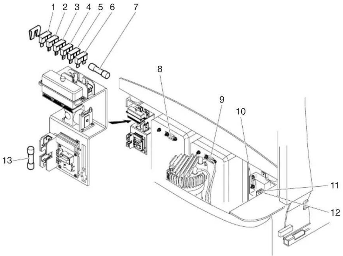
text_image
Technical diagram of an electronic device with numbered components for identification| Item | Designation Electric circuit Rating / type | ||||||
| 1 | O | p | t | ||||
| 2 | F | 3 | . | 1 | C | o | n |
| 3 | F | 4 | C | o | n | t | |
| 4 | F | 1 | . | 2 | C | o | n |
| 5 | F | 2 | . | 1 | C | o | n |
| 6 | 1 | F | 9 | C | o | n | t |
| 7 | F | 1 | O | v | e | r | |
| 8 | 2 | F | 1 | 0 | C | o | n |
| 9 | 1F | Control-circuit fuse, travelling | 250 A / 355 A | ||||
| 10 | F8 | Main fuse | 425 A | ||||
| 11 | 5F2 | Control circuit fuse, DC/DC converter (option) | 24 V 10 A | ||||
| 12 | 5F2 | Control circuit fuse, DC/DC converter (option) | 24 V 15 A | ||||
| 13 | 3F1 | Steering booster motor | 30 A | ||||
i t r t t r a t
6.13 Recommissioning after cleaning or maintenance operations
Recommissioning of the truck following the performance of cleaning or maintenance work is permitted only after the following operations have been performed:
- Check the horn for proper functioning.
- Check the master switch for correct functioning.
- Check the brake for correct functioning.
- Lubricate truck according to lubrication schedule.
7 D e c o m m i s s i o n i n
If the fork lift truck is to be decommissioned for more than two months, it must be parked in a frost-free and dry location and all measures to be taken before, during and following decommissioning must be performed as detailed below.
During decommissioning, the fork lift truck must be jacked up, ensuring that the wheels are clear of the ground. Only this measure will ensure that wheels and wheel bearings do not suffer damage.
If the fork lift truck is to be decommissioned for more than 6 months, additional measures must be discussed with the Service Department of the manufacturer.
7.1 Operations to be performed prior to decommissioning
- Thoroughly clean the fork lift truck.
- Check the brakes for correct function.
- Check the hydraulic oil level and top up if required (refer to chapter F).
- Apply a thin film of oil or grease to all parts not protected by a paint coating.
- Grease the fork lift truck as detailed in the lubrication chart (refer to chapter F).
– Recharge the battery (refer to chapter D). - Disconnect and clean the battery. Apply pole grease to the battery poles.
In addition to this, all instructions given by the battery supplier must be observed.
- Spray all exposed electrical contacts with a suitable contact spray.
7.2 Measures to be taken during decommissioning
Every 2 months:
– Recharge the battery (refer to chapter D).
⚠️ Battery-operated fork lift trucks: Regular recharging of the battery is very important; otherwise, exhaustive depletion of the battery caused by self-discharging would occur. Owing to sulfatisation, this will result in the destruction of the battery.
7.3 Recommissioning the truck
- Thoroughly clean the fork lift truck.
- Lubricate the fork lift truck according to the lubrication chart (refer to chapter F).
- Clean the battery. Grease the pole screws using pole grease and reconnect the battery.
– Recharge the battery (refer to chapter D). - Check if the gear oil contains condensed water and change if required.
- Check if the hydraulic oil contains condensed water and change if required.
- Start up the fork lift truck (refer to chapter E).

Battery-operated fork lift trucks:
If switching troubles are experienced in the electric system, spray the exposed contacts with contact spray and remove any oxide layer on the contacts of the operating controls by repeated operation.

Perform several brake tests immediately after recommissioning the truck.
8 S a f e t y t e s t s t c

Perform a safety check in accordance with national regulations. Jungheinrich recommends the truck be checked to FEM guideline 4.004. Jungheinrich has a safety department with trained personnel, able to carry out inspections.
The truck must be inspected at least annually or after any unusual event by a qualified inspector (be sure to comply with national regulations). The inspector shall assess the condition of the truck from purely a safety viewpoint, without regard to operational or economic circumstances. The inspector shall be sufficiently instructed and experienced to be able to assess the condition of the truck and the effectiveness of the safety mechanisms based on the technical regulations and principles governing the inspection of forklift trucks.
A thorough test of the truck must be undertaken with regard to its technical condition from a safety aspect. The truck must also be examined for damage caused by possible improper use. A test report shall be provided. The test results must be kept for at least the next 2 inspections.
The owner is responsible for ensuring that faults are immediately rectified.

A test plate is attached to the truck as proof that it has passed the safety inspection. This plate indicates the due date for the next inspection.
9 F i n a l d e - c o m m i

Final, correct de-commissioning or disposal of the truck must be performed in accordance with the regulations of the country of use. In particular, regulations governing the disposal of batteries, fuels and electronic and electrical systems must be observed.
Instructions for use
Jungheinrich traction battery
Table of contents
1 J u n g h e i n r i c h t r
with positive tubular plates type EPzS and EPzB....2-6
Type plate Jungheinrich traction battery....7
Instruction for use
Aquamatic/BFS III water refilling system....8-12
2 J u n g h e i n r i c h t r
Maintenance free traction batteries with positive tubular plates type EPzV
and EPzV-BS 13-17
Type plate Jungheinrich traction battery....17
1 J u n g h e i n r i c h t
with positive tubular plates type EPzS and EPzB
Rating Data
- Nominal capacity C5: See type plate
- Nominal voltage: 2,0 V x No of cells
- Discharge current:: C5/5h
- Nominal S.G. of electrolyte*
Type EPzS: 1,29 kg/l
Type EPzB: 1,29 kg/l -
Rated temperature: 30^ C
-
Nominal electrolyte level: up to electrolyte level mark „max.“
* Will be reached within the first 10 cycles.


- Pay attention to the operation instruction and fix them close to the battery!
•Work on batteries to be carried out by skilled personnel only!

- Use protective glasses and clothes when working on batteries!
- Pay attention to the accident prevention rules as well as DIN EN 50272-3, DIN 50110-1!

- No smoking!
- Do not expose batteries to naked flames, glowing embers or sparks, as it may cause the battery to explode!
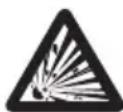
- Acid splashes in the eyes or on the skin must be washed with water. In case of accident consult a doctor immediately!
- Clothing contaminated by acid should be washed in water.
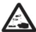
- Risk of explosion and fire, avoid short circuits!
•Electrolyte is highly corrosive!

•Batteries and cells are heavy!
- Ensure secure installation! Use only suitable handling equipment e.g. lifting gear in accordance with VDI 3616.
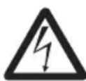
•Dangerous electrical voltage!
- Caution! Metal parts of the battery are always live. Do not place tools or other metal objects on the battery!
Ignoring the operation instructions, repair with non-original parts or using additives for the electrolyte will render the warranty void.
For batteries in classes ☒ I and ☒ II the instructions for maintaining the appropriate protection class during operation must be complied with (see relevant certificate).
1. Commissioning filled and charged batteries. For commissioning of unfilled batteries see separate instructions!
The battery should be inspected to ensure it is in perfect physical condition.
The charger cables must be connected to ensure a good contact, taking care that the polarity is correct. Otherwise battery, vehicle or charger could be damaged.
The specified torque loading for the polscrews of the charger cables and connectors are:
| steel | |
| M 10 23 | ± 1 Nm |
The level of the electrolyte must be checked. If it is below the antisurge baffle or the top of the separator it must first be topped up to this height with purified water.
The battery is then charged as in item 2.2.
The electrolyte should be topped up to the specified level with purified water.
2. Operation
DIN EN 50272-3 «Traction batteries for industrial trucks» is the standard which applies to the operation traction batteries in industrial trucks.
2.1 Discharging
Be sure that all breather holes are not sealed or covered.
Electrical connections (e.g. plugs) must only be made or broken in the open circuit condition.
To achieve the optimum life for the battery, operating discharges of more than 80% of the rated capacity should be avoided (deep discharge).
This corresponds to an electrolyte specific gravity of 1.13 kg/l at the end of the discharge. Discharged batteries must be recharged immediately and must not be left discharged. This also applies to partially discharged batteries.
2.2 Charging
Only direct current must be used for charging. All charging procedures in accordance with DIN 41773 and DIN 41774 are permitted. Only connect the battery assigned to a charger, suitable for the size of battery, in order to avoid overloading of the electric cables and contacts, unacceptable gassing and the escape of electrolyte from the cells.
In the gassing stage the current limits given in DIN EN 50272-3 must not be exceeded. If the charger was not purchased together with the battery it is best to have its suitability checked by the manufacturers service department. When charging, proper provision must be made for venting of the charging gases.
Battery container lids and the covers of battery compartments must be opened or removed. The vent plugs should stay on the cells and remain closed.
With the charger switched off connect up the battery, ensuring that the polarity is correct. (positive to positive, negative to negative). Now switch on the charger. When charging the temperature of the electrolyte rises by about 10^ C, so charging should only begin if the electrolyte temperature is below 45^ C. The electrolyte temperature of batteries should be at least +10^ C before charging otherwise a full charge will not be achieved.
A charge is finished when the specific gravity of the electrolyte and the battery voltage have remained constant for two hours. Special instructions for the operation of batteries in hazardous areas. This concerns batteries which are used in accordance with EN 50014, DIN VDE 0170/0171 Ex (in areas with a firedamp hazard) or Ex II (in potentially explosive areas). During charging and subsequent gassing the container lids must be removed or opened so that the explosive mixture of gases loses its flammability due to adequate ventilation. The containers for batteries with plate protection packs must not be closed until at least half an hour after charging has past.
2.3 Equalising charge
Equalising charges are used to safeguard the life of the battery and to maintain its capacity. They are necessary after deep discharges, repeated incomplete recharges and charges to an IU characteristic curve. Equalising charges are carried out following normal charging. The charging current must not exceed 5 A/100 Ah of rated capacity (end of charge - see point 2.2).
Watch the temperature!
2.4 Temperature
An electrolyte temperature of 30^ C is specified as the rated temperature. Higher temperatures shorten the life of the battery, lower temperatures reduce the capacity available. 55^ C is the upper temperature limit and is not acceptable as an operating temperature.
2.5 Electrolyte
The rated specific gravity (S. G.) of the electrolyte is related to a temperature of 30^ C and the nominal electrolyte level in the cell in fully charged condition. Higher temperatures reduce the specified gravity of the electrolyte, lower temperatures increase it. The temperature correction factor is -0.0007 kg/l per ^ C, e.g. an electrolyte specific gravity of 1.28 kg/l at 45^ C corresponds to an S.G. of 1.29 kg/l at 30^ C.
The electrolyte must conform to the purity regulations in DIN 43530 part 2.
3. Maintenance
3.1 Daily
Charge the battery after every discharge. Towards the end of charge the electrolyte level should be checked and if necessary topped up to the specified level with purified water. The electrolyte level must not fall below the anti-surge baffle or the top of the separator or the electrolyte „min“ level mark.
3.2 Weekly
Visual inspection after recharging for signs of dirt and mechanical damage. If the battery is charged regularly with a IU characteristic curve an equalising charge must be carried out (see point 2.3).
3.3 Monthly
At the end of the charge the voltages of all cells or bloc batteries should be measured with the charger switched on, and recorded. After charging has ended the specific gravity and the temperature of the electrolyte in all cells should be measured and recorded.
If significant changes from earlier measurements or differences between the cells or bloc batteries are found further testing and maintenance by the service department should be requested.
3.4 Annually
In accordance with DIN VDE 0117 at least once per year, the insulation resistance of the truck and the battery must be checked by an electrical specialist.
The tests on the insulation resistance of the battery must be conducted in accordance with DIN EN 60254-1.
The insulation resistance of the battery thus determined must not be below a value of 50 per Volt of nominal voltage, in compliance with DIN EN 50272-3.
For batteries up to 20 V nominal voltage the minimum value is 1000 Ω.
4. Care of the battery
The battery should always be kept clean and dry to prevent tracking currents. Cleaning must be done in accordance with the ZVEI code of practice «The Cleaning of Vehicle Traction batteries».
Any liquid in the battery tray must be extracted and disposed of in the prescribed manner. Damage to the insulation of the tray should be repaired after cleaning, to ensure that the insulation value complies DIN EN 50272-3 and to prevent tray corrosion. If it is necessary to remove cells it is best to call in our service department for this.
5. Storage
If batteries are taken out of service for a lengthy period they should be stored in the fully charged condition in a dry, frost-free room. To ensure the battery is always ready for use a choice of charging methods can be made:
- a monthly equalising charge as in point 2.3
- float charging at a charging voltage of 2.23 V x the number of cells. The storage time should be taken into account when considering the life of the battery.
6. Malfunctions
If malfunctions are found on the battery or the charger our service department should be called in without delay. The measurements taken in point 3.3 will facilitate fault finding and their elimination.
A service contract with us will make it easier to detect and correct faults in good time.
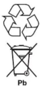
chemical
Chemical symbols for a recycling and discharge mechanism, including a trigonal cycle and a Pb (potassium) symbolBack to the manufacturer!
Batteries with this sign must be recycled.
Batteries which are not returned for the recycling process must be disposed of as hazardous waste!
We reserve the right make technical modification.
- Type plate, Jungheinrich traction battery
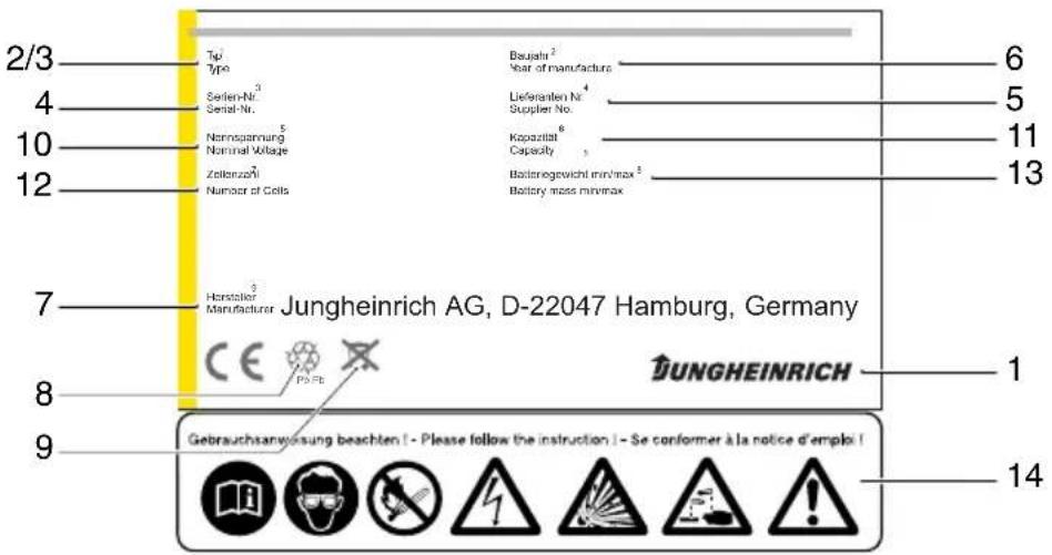
* CE mark is only for batteries with a nominal voltage greater than 75 volt.
Aquamatic/BFS III water refilling system for Jungheinrich traction battery with EPzS and EPzB cells with tubular positive plates
Aquamatic plug arrangement for the Operating Instructions
| Cell series* Aquamatic plug type (length) | |||
| EPzS | EPzB | Frötek (yellow) | BFS (black) |
| 2/120 – 10/ 600 | 2/ 42 – 12/ 252 | 50,5 mm | 51,0 mm |
| 2/160 – 10/ 800 2/ 64 – 12/ 384 50,5 mm 51,0 mm | |||
| – 2/ 84 – 12/ 504 50,5 mm 51,0 mm | |||
| – | 2 / | 1 1 | 0 |
| – | 2/130 – 12/ 780 | 50,5 mm | 51,0 mm |
| – | 2 / | 1 5 | 0 |
| – | 2/172 – 12/1032 | 50,5 mm | 51,0 mm |
| – | 2/200 – 12/1200 | 56,0 mm | 56,0 mm |
| – | 2/216 – 12/1296 | 56,0 mm | 56,0 mm |
| 2/180 – 10/900 – 61,0 mm 61,0 mm | |||
| 2/210 – 10/1050 | – | 61,0 mm | 61,0 mm |
| 2/230 – 10/1150 | – | 61,0 mm 61,0 mm | |
| 2/250 – 10/1250 | – | 61,0 mm | 61,0 mm |
| 2/280 – 10/1400 | – | 72,0 mm 66,0 mm | |
| 2/310 – 10/1550 | – | 72,0 mm | 66,0 mm |
* The cell series comprise cells with two to ten (twelve) positive plates, e.g. column EPzS. 2/120 - 10/600.
These are cells with the positive plate 60Ah. The type designation of a cell is e.g. 2 EPzS 120.
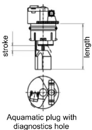
text_image
stroke length Aquamatic plug with diagnostics hole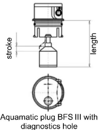
text_image
stroke length Aquamatic plug BFS III with diagnostics holeNon-adherence to the operating instructions, repairs carried out with non-original spare parts, unauthorised interference, and the use of additives for the electrolytes (alleged improvement agents) will invalidate any claim for warranty.
When using batteries which comply with ExI and ExII, it is important to follow the instructions on maintaining the respective protection class during operation (see associated certification).
Diagrammatic view
Equipment for the water refilling system
- Water tank
- Level switch
- Discharge point with ball valve
- Discharge point with sole-noid valve
- Charger
- Sealing coupler
- Closing nipple
- Ion exchange cartridge with conductance meter and solenoid valve
- Connection for untreated water
- Charging lead
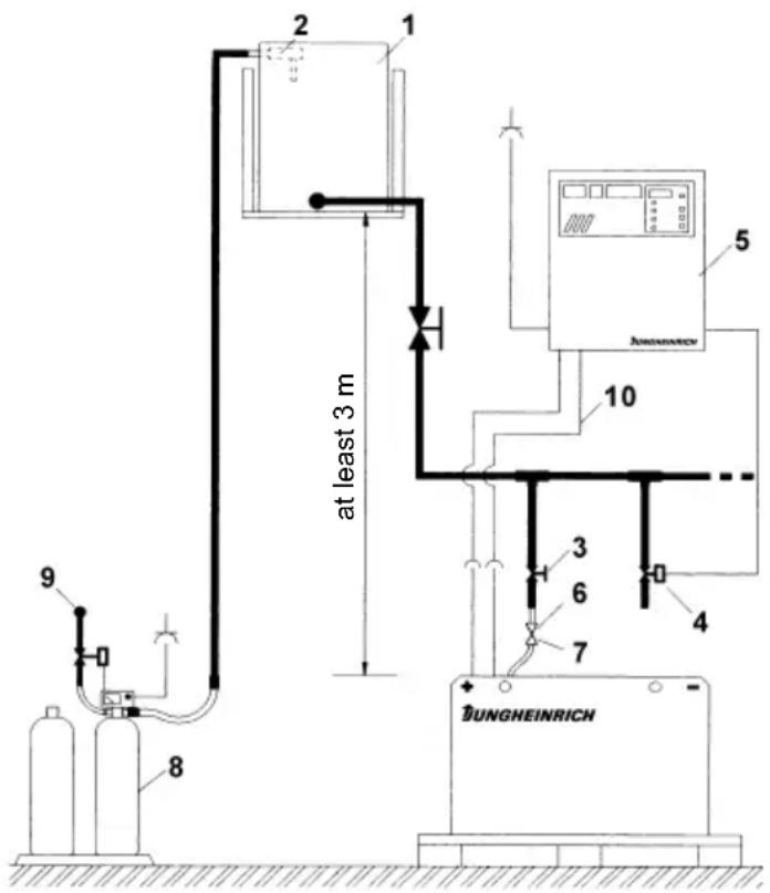
text_image
at least 3 m 8 9 1 2 1 5 AUXONANCE 10 3 6 4 7 BUNGHEINRICH1. Design
The Aquamatic/BFS battery water refilling systems are used for automatically adjusting the nominal electrolyte level. Venting holes are provided for letting off the gases which arise during charging. In addition to the optical level indicator, the plug systems also have a diagnostics hole for measuring the temperature and the electrolyte density. All battery cells of the design series EPzS; EPzB can be equipped with the Aquamatic/BFS filling systems. The water can be refilled by means of a central sealing coupler through the hose connections in the individual Aquamatic/BFS plugs.
2. Application
The Aquamatic/BFS battery water refilling system is used in traction batteries for forklift trucks. The water refilling system is provided with a central water connection for the water supply. Soft PVC hose is used for this connection and for the hose connections for the individual plugs. The hose ends are put onto the hose connection sleeves located on the T or < pieces.
3. Function
The quantity of water required in the refilling process is controlled by the valve located in the plug in combination with the float and the float rods. In the Aquamatic System the existing water pressure at the valve turns off the water supply and ensures that the valve closes securely. When the maximum filling level is reached in the BFS system, the float and the float rods through a lever system close the valve with five times the buoyant force and consequently interrupt the water supply reliably.
4. Filling (manual/automatic)
The batteries should be filled with battery water as soon as possible before the battery charging comes to an end; this ensures that the refilled water quantity is mixed with the electrolyte. In normal operation it is usually sufficient to fill once a week.
5. Connection pressure
The water refilling unit is to be operated in such a way that the water pressure in the water pipe is between 0.3 bars and 1.8 bars. The Aquamatic System has an operating pressure range of between 0.2 bars and 0.6 bars. The BFS system has an operating pressure range of 0.3 bars to 1.8 bars. Deviations from the pressure ranges impair the system's functional reliability. This wide pressure range permits three types of filling.
5.1 Falling water
The height of the tank is chosen to suit whichever water refilling system is used. For the Aquamatic System the installation height is 2 m to 6 m and for the BFS system the installation height is 3 m to 18 m over the battery surface.
5.2 Pressurised water
The pressure-reducing valve in the Aquamatic System is set from 0.2 bars to 0.6 bars and from 0.3 bars to 1.8 bars in the BFS system.
5.3 Water Refill Trolley (serviceMobil)
The submergible pump located in the ServiceMobil's tank generates the necessary filling pressure. No difference in height is permitted between the standing level of the ServiceMobil and the standing level of the battery.
6. Filling duration
The length of time needed to fill the batteries depends on the conditions under which the battery is used, the ambient temperatures and the type of filling and/or the filling pressure. The filling time is approx. 0.5 to 4 minutes. Where filling is manual, the water feed pipe must be separated from the battery after filling.
7. Water quality
Only refilling water which conforms in quality to DIN 43530 part 4 may be used to fill the batteries. The refilling unit (tank, pipelines, valves etc.) may not contain any kind of dirt which could impair the functional reliability of the Aquamatic/BFS plug. For safety reasons it is recommendable to insert a filter element (optional) with a max. passage opening of 100 to 300 m into the battery's main supply pipe.
8. Battery hose connections
Hose connections for the individual plugs are laid along the existing electric circuit. No changes may be made.
9. Operating temperature
The temperature limit for battery operation is set at 55^ C. Exceeding this temperature damages the batteries. The battery filling systems may be operated within a temperature range of >0^ C to a maximum of 55^ C.
CAUTION:
Batteries with automatic water refilling systems may only be operated in rooms with temperatures >0^ C (as there is otherwise a danger that the systems may freeze).
9.1 Diagnostics hole
To be able to measure the acid density and temperature easily, the water refilling systems must have a diagnostics hole with a 6.5 mm-diameter (Aquamatic plugs) or a 7.5 mm-diameter (BFS plugs).
9.2 Float
Different floats are used depending on the cell design and type.
9.3 Cleaning
The plug systems may only be cleaned with water. No parts of the plugs may come in contact with soap or fabrics which contain solvents.
10. Accessories
10.1 Flow indicator
To monitor the filling process, a flow indicator can be inserted into the water feed pipe on the battery side. During the filling process, the paddlewheel is turned by the flowing water. When the filling process ends, the wheel stops and this indicates the end of the filling process. (ident no.: 50219542).
10.2 Plug lifter
Only the appertaining special-purpose tool may be used to disassemble the plug systems (plug lifter). The greatest of care must be employed when prising out the plug to prevent any damage to the plug systems.
10.2.1 Clamping ring tool
The clamping ring tool is used to push on a clamping ring to increase the contact pressure of the hose connection on the plugs' hose couplings and to loosen it again.
10.3 Filter element
For safety reasons a filter element (ident no.: 50307282) can be fitted into the battery's main supply pipe for supplying battery water. This filter element has a maximum passage cross-section of 100 to 300 m and is designed as a bag filter.
10.4 Sealing coupler
The water is supplied to the water refilling systems (Aquamatic/BFS) through a central supply pipe. This is connected to the water supply system at the battery charging station by means of a sealing coupler system. On the battery side a closing nipple (ident no.: 50219538) is mounted and the customer must place a sealing coupler construction on the water supply side (obtainable under ident. no.: 50219537).
11. Functional data
PS - self-sealing pressure: Aquamatic > 1.2 bars
BFS system none
D - rate of flow in the opened valve when the pressure is 0.1 bars: 350 ml/min
D1 - maximum permissible leakage rate in the closed valve when the pressure is at 0.1 bars: 2 ml/min
T - p e r m i s s i b l e t e m p e r a t u r e
Pa - operating pressure range: 0.2 to 0.6 bars in the Aquamatic system and operating pressure range: 0.3 to 1.8 bars in the BFS system.
Betriebsanleitung
D
52020418
04.10
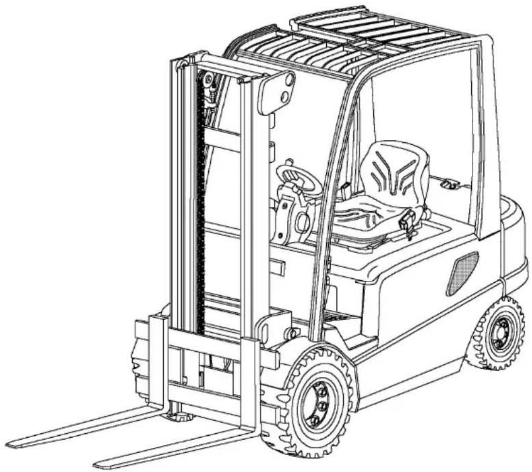
natural_image
Line drawing of a forklift carrying a vehicle, showing front wheel, side lock, and gear mechanism (no text or symbols)Vorwort
natural_image
Line drawing of a forklift carrying a vehicle, showing front wheel, side lock, and gear mechanism (no text or symbols)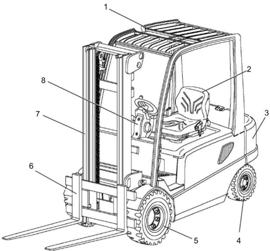
text_image
Technical diagram of a forklift with numbered parts labeled for identification1) = + 25 mm DZ-Mast
1) = + 25 mm DZ-Mast
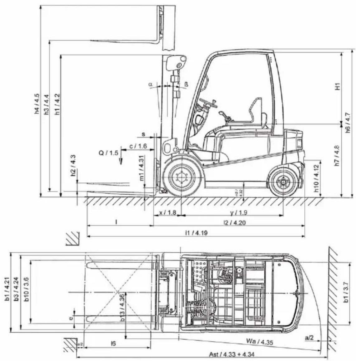
text_image
h4/4.5 h3/4.4 h1/4.2 h2/4.3 Q/1.5 c/1.6 m1/4.31 s x/1.8 y/1.9 l2/4.20 l1/4.19 H1 h7/4.8 h6/4.7 a b b3/4.24 b10/3.6 e b3/4.36 b1/3.7 b1/4.21 l6 Wa/4.35 a/2 Ast/4.33 + 4.343.1 Leistungsdaten
EFG 425ks/425s/430 = 71 dB(A)
text_image
Technical diagram of a forklift with numbered parts and safety symbols, including warning signs, vehicle diagrams, and safety warnings.other
| Dimension | Value | |---|---| | h3 (mm) | 4250 | | h3 (mm) | 3600 | | h3 (mm) | 2900 | | Q (kg) | 850 | | Q (kg) | 1105 | | Q (kg) | 1250 | | Q (kg) | 850 | | D (mm) | 500 | | D (mm) | 600 | | D (mm) | 700 | Nr. : | Position Label: Nr. : | Subtitle: Q (kg): | Horizontal Labels: d(mm): 4250, 3600, 2900 | | Horizontal Labels: d(mm): 850, 1105, 1250 | | Horizontal Labels: d(mm): 850, 600, 850, 850 | The chart is a schematic representation of a mechanical part with labeled dimensions.natural_image
Line drawing of a forklift lifting a load, no text or symbols present
natural_image
Technical line drawing of a robotic vehicle showing front wheel, side wheels, and dashboard (no text or symbols)2 S i c h e r u n g d e s

natural_image
Line drawing of a forklift carrying a vehicle, no text or symbols presentnatural_image
Line drawing of a forklift with visible frame and wheels (no text or symbols)natural_image
Technical line drawing of a forklift with dimensional annotations (no text or symbols)text_image
Technical diagram showing mechanical assembly with labeled component '2' and directional arrow indicating rotation or adjustment.text_image
Technical diagram of a car interior with numbered components for identification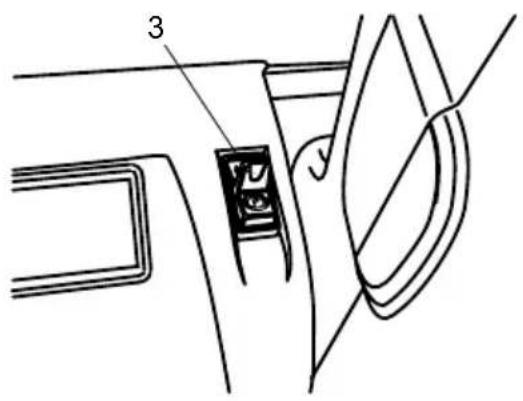
text_image
Technical diagram showing a mechanical component with labeled parts 3 and 4, likely illustrating a turning or assembly process.natural_image
Line drawing of a forklift operator in a truck, showing no text or symbols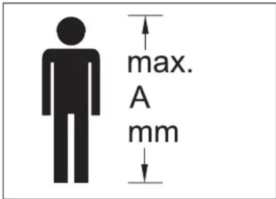
text_image
max. A mmnatural_image
Diagram of a forklift lifting a truck, showing motion direction (no text or symbols)Last transportieren

natural_image
Diagram showing a forklift lifting a table and a load, with no text or symbols present.text_image
Technical diagram showing a mechanical component with labeled parts 3 and 4, likely from an engineering or manufacturing context.text_image
Technical diagram of a forklift system with labeled components and directional indicators (A, E, D)$$ M _ {A} = 3 3 0 N m $$
$$ M _ {A} = 2 2 0 N m $$
Räder / Lenkachse
$$ M _ {A} = 1 7 0 \mathrm{Nm} $$