EFG D30 - Forklift Jungheinrich - Free user manual and instructions
Find the device manual for free EFG D30 Jungheinrich in PDF.


User questions about EFG D30 Jungheinrich
0 question about this device. Answer the ones you know or ask your own.
Ask a new question about this device
Download the instructions for your Forklift in PDF format for free! Find your manual EFG D30 - Jungheinrich and take your electronic device back in hand. On this page are published all the documents necessary for the use of your device. EFG D30 by Jungheinrich.
USER MANUAL EFG D30 Jungheinrich
Operating Instructions
GB
52039353
07.08
natural_image
Technical line drawing of a forklift carrying a large cylindrical component (no text or symbols)Foreword
The present ORIGINAL OPERATING INSTRUCTIONS are designed to provide sufficient instruction for the safe operation of the industrial truck. The information is provided clearly and concisely. The chapters are arranged by letter. Each chapter starts with page 1. The page identification consists of a chapter letter and a page number.
For example: Page B 2 is the second page in chapter B.
The operating instructions detail different truck models. When operating and servicing the truck, make sure that the instructions apply to your truck model.
Safety instructions and important explanations are indicated by the following graphics:

Used before safety instructions which must be observed to avoid danger to personnel.

Used before notices which must be observed to avoid material damage.

Used before notices and explanations.
●Used to indicate standard equipment.
○Used to indicate optional equipment.
Our trucks are subject to ongoing development. Jungheinrich reserves the right to alter the design, equipment and technical features of the truck. No guarantee of particular features of the truck should therefore be inferred from the present operating instructions.
Copyright
Copyright of these operating instructions remains with JUNGHEINRICH AG.
2 Assemblies and Functional Description ...... B 2
2.1 Truck B 3
3 Standard Version Specifications ...... B 4
3.1 Performance data ...... B 6
3.2 Weights (all measurements in kg) ...... B 6
3.3 Tyres B 6
3.4 EN norms ...... B 7
3.5 Conditions of use B 7
4 Identification points and data plates ...... B 8
4.1 Truck data plate B 10
4.2 Truck load diagram B 10
4.3 Fork load diagram (basic model) ...... B 11
4.4 Attachment load diagram B 11
C T r a n s p o r t a n d C o
1 Lifting by crane C 1
2 Securing the truck during transport C 2
3 Using the truck for the first time C 3
4 Operating the truck without its own drive system ...... C 4
5 Steering the truck without its own drive system ...... C 5
6 Towing and lifting the truck C 5
D B a t t e r y M a i n t e n a
1 Safety regulations for handling acid batteries ...... D 1
2 Battery types ......D 2
3 Exposing the battery D 3
4 Charging the battery ....D 3
5 Battery removal and installation ...... D 4
5.1 Removal / assembly with a battery trolley ...... D 5
5.2 Removal / assembly with a battery trolley using a discharge device .. D 6
6 B a t t e r y D i s c h a r
E O p e r a t i o n
1 Safety Regulations for the Operation of Forklift Trucks ...... E 1
2 Controls and Displays E 2
3 Control panel E 4
3.1 Control panel displays E 4
3.2 Control panel buttons E 6
3.3 Driver's Display Warning Messages E 10
4 Starting up the truck E 11
4.1 Checks and operations to be performed before starting daily work .... E 11
4.2 Entering the truck E 12
4.3 Adjusting the driver's seat E 13
4.4 Safety restraint belt E 15
4.5 To prepare the truck for operation E 17
5 Industrial truck operation E 18
5.1 Safety regulations for truck operation E 18
5.2 Travel E 20
5.3 Steering E 22
5.4 Braking E 22
5.5 Operating the lift mechanism and attachments (Multipilot) ...... E 24
5.6 Collecting, transporting and depositing loads E 27
5.7 Park the truck securely E 30
5.8 Leaving the truck E 31
5.9 Towing trailers E 32
5.10 Tow loads E 32
6 Troubleshooting E 33
6.1 Additional Functions ...... E 34
F T r u c k M a i n t e n a n
1 Operational Safety and Environmental Protection ......F 1
2 Maintenance Safety Regulations ......F 1
3 Servicing and Inspection ......F 3
4 EFG Maintenance Checklist ......F 4
5 EFG Maintenance Schedule ......F 7
5.1 Consumables ......F 8
6 Maintenance and Repairs ......F 9
6.1 Prepare the truck for maintenance and repairs ......F 9
6.2 Checking the wheel attachments. ......F 9
6.3 Tyre pressure ......F 9
6.4 Checking the hydraulic oil level F 9
6.5 Check transmission oil level ......F 10
6.6 Draining the oil F 10
6.7 Adding oil ......F 11
6.8 Replacing the hydraulic oil filter ......F 11
6.9 Seat Belt Maintenance ......F 11
6.10 Checking electrical fuses ......F 12
6.11 Returning the truck to service after cleaning or repairs ......F 14
7 Decommissioning the industrial truck ......F 14
7.1 Prior to decommissioning: ......F 14
7.2 During decommissioning: F 14
7.3 Restoring the truck to operation after decommissioning ......F 15
8 S a f e t y c h e c k s t
any unusual incidents ......F 16
9 Final de-commissioning, disposal ......F 16
Appendix
JH Traction Battery Operating Instructions

These operating instructions apply only to Jungheinrich battery models. If using another brand, refer to the manufacturer's operating instructions.
A Correct use and

The “Guidelines for the Correct Use and Application of Industrial Trucks” (VDMA) are supplied with the truck. The guidelines form part of these operating instructions and must be observed. National regulations apply in full.
The truck described in the present operator manual is an industrial truck designed for lifting and transporting load units.
It must be used, operated and serviced in accordance with the present instructions. Any other type of use is beyond the scope of application and can result in damage to personnel, the truck or property. In particular, avoid overloading the truck with loads which are too heavy or placed on one side. The data plate attached to the truck and the load diagram are binding with regard to the maximum load capacity. The owner must ensure that any damaged and/or illegible load diagrams are replaced. The industrial truck must not be used in fire or explosion endangered areas, or areas threatened by corrosion or excessive dust.
Proprietor responsibilities: For the purposes of the present operator manual the “proprietor” is defined as any natural or legal person who either uses the industrial truck himself, or on whose behalf it is used. In special cases (e.g. leasing or renting) the proprietor is considered the person who, in accordance with existing contractual agreements between the owner and user of the industrial truck, is charged with operational duties.
The proprietor must ensure that the industrial truck is used only for the purpose it is intended for and that danger to life and limb of the user and third parties are excluded. Furthermore, accident prevention regulations, safety regulations and operating, servicing and repair guidelines must be followed. The proprietor must ensure that all truck users have read and understood this operator manual.

Failure to comply with the operator manual shall invalidate the warranty. The same applies if improper work is carried out on the truck by the customer or third parties without the permission of the manufacturer's customer service department.
Attaching accessories: The attachment or installation of additional equipment which affects or enhances the performance of the industrial truck requires the written permission of the manufacturer. In some cases, local authority approval shall be required.
Approval of the local authorities however does not constitute the manufacturer's approval.
Trailing and towed loads: The truck may only be used for trailing or towed loads for which the truck has been approved.
B Truck Descriptio
1 A p p l i c a t i o n
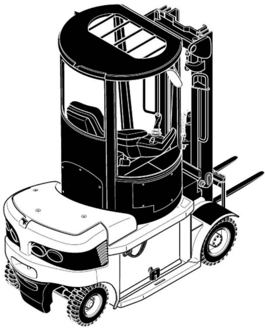
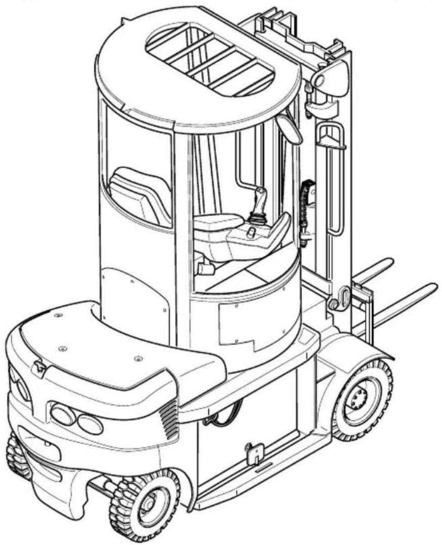
The EFG-D30 is a 4-wheel electric sit-down truck with front wheel drive which collects, transports and lifts its load outside the wheelbase. It is a cantilevered counterbalanced truck, which with the load handler mounted on the front of the truck can unload lorries without hindrance and deposit the load on ramps or in aisles. It can stack and transport DIN 15142 pallets, DIN 15144 wire box pallets and other palletised loads.
Truck types and maximum capacity:
| Type Max. capacity *) Load centre of gravity | |
| EFG-D30 3,000 kg 500 mm |
*) The load diagrams attached to the truck are binding in terms of capacity
natural_image
Technical line drawing of a forklift carrying a truck, showing internal components and mounting brackets (no text or symbols)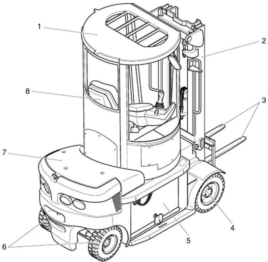
text_image
Technical diagram of a forklift with numbered parts labeled 1 through 8| Item Description |
| 1 ●Rotating cab |
| 2 ●Mast |
| 3 ●Forks |
| 4 ●Drive axle |
| 5 ●Battery |
| 6 ●Steering axle |
| 7 ●Cover |
| 8 ●Driver's seat |
2.1 Truck
Steering (6): The travel speed reduces as a function of the steering angle ("CurveControl"). The steering angle is shown in the display.
Driver's seat (8): The driver's seat is comfortably designed. There are storage facilities for paper and the driver's personal items. The Multi Pilot combines all the hydraulic functions and the travel direction switch in one lever. The armrests are adjustable and cushioned.
Electrical/electronic system: State-of-the-art electronics provide data transmission (CAN Bus) with a minimum of cable leads. The driver can choose from a range of operating programs, from maximum performance to economy, depending on the load and the environment.
Drive system and brakes: The front drive provides maximum traction to the drive wheels at all times.
The hydraulic oil bath multi-plate brake acts as a practically maintenance-free parking brake. The truck also brakes to a halt regeneratively via the traction motor. This minimises energy consumption.
The spring-loaded accumulator brake applies approx. 5 seconds after the truck comes to a halt or 1 to 15 seconds (adjustable) after the driver's seat has been vacated.
The spring-loaded accumulator brake is automatically released again when the accelerator is pressed.
Hydraulic System: All operations can be performed sensitively, proportionally and simultaneously (insofar as they do not affect safety). To ensure greater efficiency, a hydraulic unit and steering booster motor operate independently of each other. The micro pressure filter can be replaced from the top (without spilling hydraulic oil).
Mast: The maximum strength steel sections are narrow, allowing for good fork visibility in particular with the three-stage mast.
The mast and the fork carriage run on permanently-lubricated and hence maintenance-free angled casters.
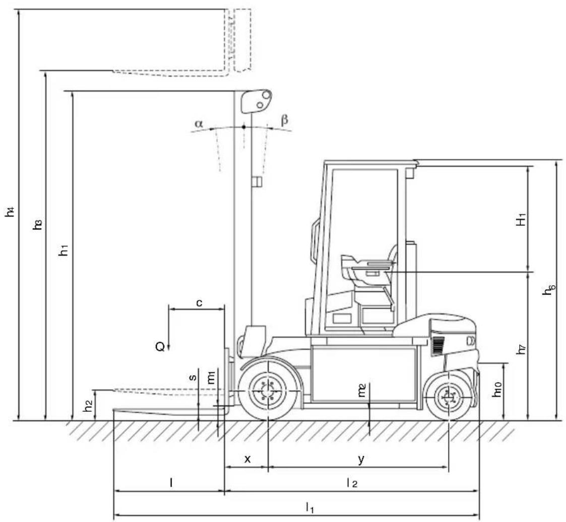
| Description EFG-D30 | |||
| h_1 | Mast height (retracted) 2200 mm | ||
| h_2 | Free lift 150 mm | ||
| h_3 | Lift 3100 mm | ||
| h_4 | Mast height (extended) 3806 mm | ||
| αMast/fork carriage tilt, fwd. 6 ° | |||
| βMast/fork carriage tilt, rev. 5 ° | |||
| h_6 | Overhead guard head 2560 mm | ||
| h_7 | Seat height / standing height | 1512 mm | |
| H_1 | Seat freedom H1 | 1100 mm | |
| h_10 | Coupling height | 390/550 | mm |
| l_1 | Overall length including forks | 3621 mm | |
| l_2 | Headlength | 2521 mm | |
| b1 | Overall width | 1276 mm | |
| b3 | Fork carriage width | 1120 mm | |
| m_1 | Ground clearance with load below mast | 110 mm | |
| m_2 | Centre wheelbase ground clearance | 125 mm | |
| Ast | Aisle width800 x 1200 longitudinal pallets | 4080 mm | |
| Ast | Aisle width1200 x 800 traverse pallets | 4280 mm | |
| W_a | Turning radius | 2450 mm | |
| x | Load distance | 430 ^1 | mm |
| y | Wheelbase | 1775 | mm |
1) = + 31 mm DZ mast
text_image
h4 h3 h1 α β c Q s m1 h2 x y l2 l1 h6 h7 h10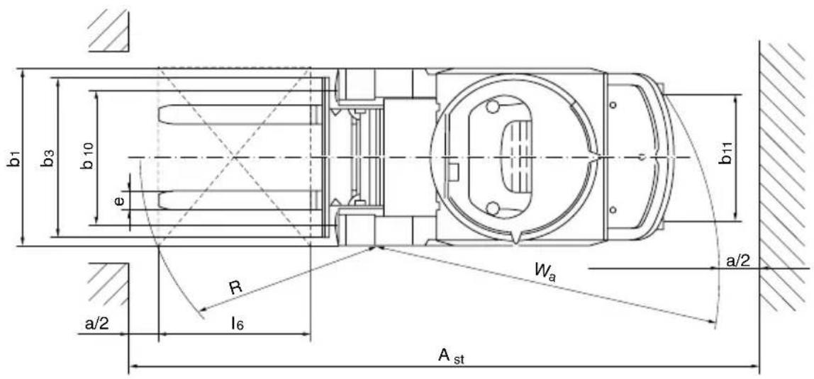
text_image
b1 b3 b 10 φ b11 a/2 R l6 Wₐ Aₛₜ3.1 Performance data
| Description EFG-D30 | |||
| Q | Capacity / Load | 3.0 t | |
| c | Load centre of | gravity | |
| Travel speed w / w.o. load 19/19.9 km/h | |||
| Lift speedw / w.o. load | 0.50/0.67 m/s | ||
| Lowering speedw / w.o. load | 0.57/0.56 m/s | ||
| Gradeabilityw / w.o. load S2 30 min. | 10/17 % | ||
| Max. gradeabilityw / w.o. load S2 5 min. | 18/29 % | ||
| Acceleration timew / w.o. load to 10m | 4.32/3.83 s |
5 0
3.2 Weights (all measurements in kg)
| Description | EFG-D30 | |
| Net weight (including battery) 5074 kg | ||
| Battery weight | 1445 | kg |
| Axle load with load front/rear | 7241/858 | kg |
| Axle load w.o. load front/rear | 2462/2612 | kg |
3.3 Tyres
| Model | EFG D30 | |
| Tyre size, front | SE | 23 x 10 - 12 |
| Rubber | 22 x 9 x 16 | |
| Pneumatic | 250 / 60 R12 ; 10 bar | |
| Tyre size, rear | SE | 18 x 7 - 8 |
| Rubber | 18 x 6 x 12 1/8“ | |
| Pneumatic | 180 / 70 R8 ; 7 bar |

Permissible tyres: See chapter F "Forklift Truck Maintenance". For any queries please contact your Jungheinrich customer adviser.
3.4 EN norms
Noise emission: 67 dB(A)
in accordance with EN 12053 as harmonised with ISO 4871.
The noise emission level is calculated in accordance with standard procedures and takes into account the noise level when travelling, lifting and when idle. The noise level is measured at the driver's ear.
Vibration : aw,zS = 0.48 m/s
2
in accordance with EN 13059
The vibration acceleration acting on the body in the operating position is, in accordance with standard procedures, the linearly integrated, weighted acceleration in the vertical direction. It is calculated when travelling over bumps at constant speed.
Electromagnetic compatibility (EMC)
The manufacturer confirms that equipment complies with tolerance levels for electromagnetic emissions and resistance as well as static electricity discharge testing in accordance with EN 12895 including the normative procedures contained therein.
No changes to electric or electronic components or their arrangement may be made without the written agreement of the manufacturer.
3.5 Conditions of use
Ambient temperature
- operating at -20 °C to 40 °C
→ Special equipment and authorisation are required if the truck is to be constantly used in conditions of extreme temperature or air humidity fluctuations.

Warnings and notices such as load diagrams, strap points and data plates must at all times be legible. Replace if necessary.
text_image
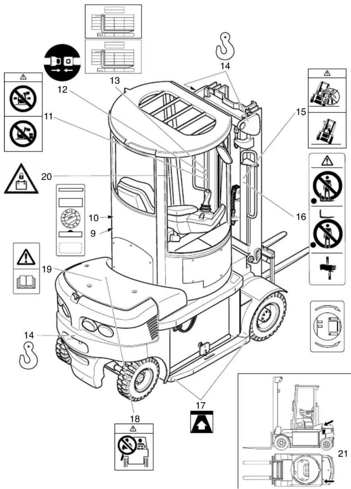
Technical diagram of a forklift with numbered parts and safety symbols, including no/no restrictions, switches, and safety indicators.| Item Description | |
| 9 | D a t a p l a t e |
| 10 Test sticker (○) | |
| 11 | “Travel with raised load prohibited” / “Mast forward tilt with raised load prohibited” warning |
| 12 Safety belt notice | |
| 13 Capacity plate | |
| 14 Jacking point notice | |
| 15 Driver response to “tipover” notice | |
| 16 | Decal: Do not step onto or beneath the load, trap point |
| 17 Strap points | |
| 18 “No passengers” notice | |
| 19 Read operating instructions notice | |
| 20 Notice: check battery latch before driving | |
| 21 Serial no. | |
4.1 Truck data plate
text_image
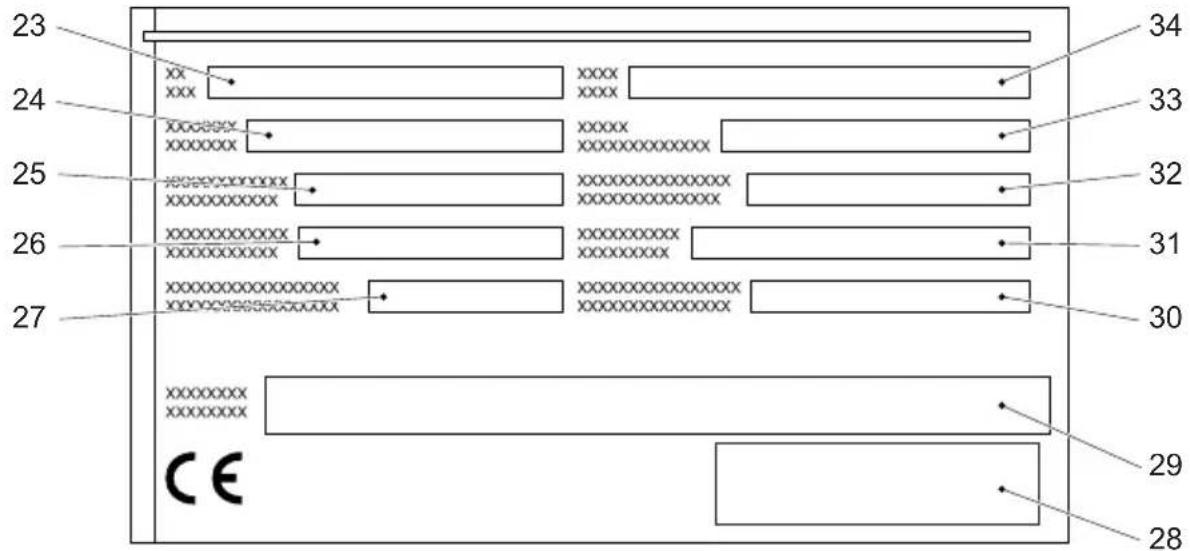
23 24 25 26 27 30 31 32 33 34 CE 29 28| Item | Description Item Description | ||
| 23 | Type 29 Manufacturer | ||
| 24 | Serial no. 30 Min./max. battery weight (kg) | ||
| 25 | Rated capacity (kg) 31 Output (kW) | ||
| 26 | Battery: Voltage V 32 Load centre of gravity (mm) | ||
| 27 | Net weight w.o. battery (kg) 33 Year of manufacture | ||
| 28 | Manufacturer's logo 34 Option |

For queries regarding the truck or ordering spare parts always quote the truck serial number (24).
4.2 Truck load diagram
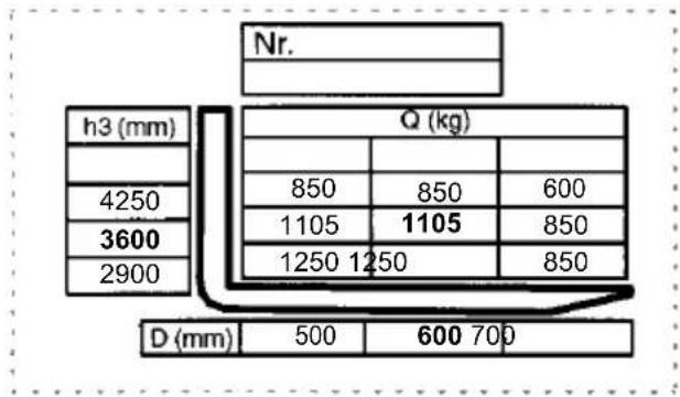
The truck load diagram gives the capacity (Q) of the truck in kg with an upright mast. The maximum capacity is shown as a table with a given load centre of gravity D (in mm) and the required lift height H (in mm).
Example:
other
| h3 (mm) | Q (kg) | |---|---| | 4250 | 850 | | 3600 | 1105 | | 2900 | 1250 | | 500 | 600 | | 700 | 700 |Example of how to calculate the maximum capacity:
With a load centre of gravity D of 600 mm and a maximum lift height H of 3600 mm. the max. capacity Q is 1105 kg.
4.3 Fork load diagram (basic model)
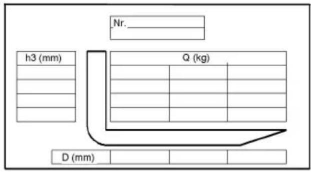
The fork load diagram give the truck's capacity Q in kg. The maximum capacity for the various load centres of gravity (D in mm) is shown in diagram form.
text_image
Nr. h3 (mm) Q (kg) D (mm)4.4 Attachment load diagram
The attachment load diagram gives the truck's capacity Q in combination with the respective attachment in kg. The serial number specified in the load diagram must match the data plate of the attachment, as the capacity for each truck is specifically indicated by the manufacturer. It is shown in the same way as the truck's capacity and can be determined accordingly.
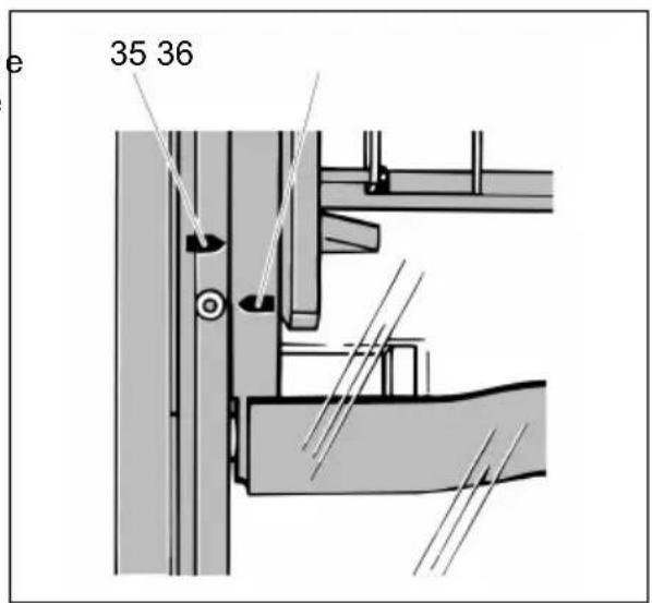
The arrow shape markings (35 and 36) on the inner and outer masts show the driver when the prescribed lift limits have been reached.
text_image
e 35 36C T r a n s p o r t and C o l
1 L i f t i n g b y c r a r

Only use lifting gear with sufficient capacity
(transport weight = net. weight + battery weight, see truck data plate).
- Park the truck securely (see Chapter E).
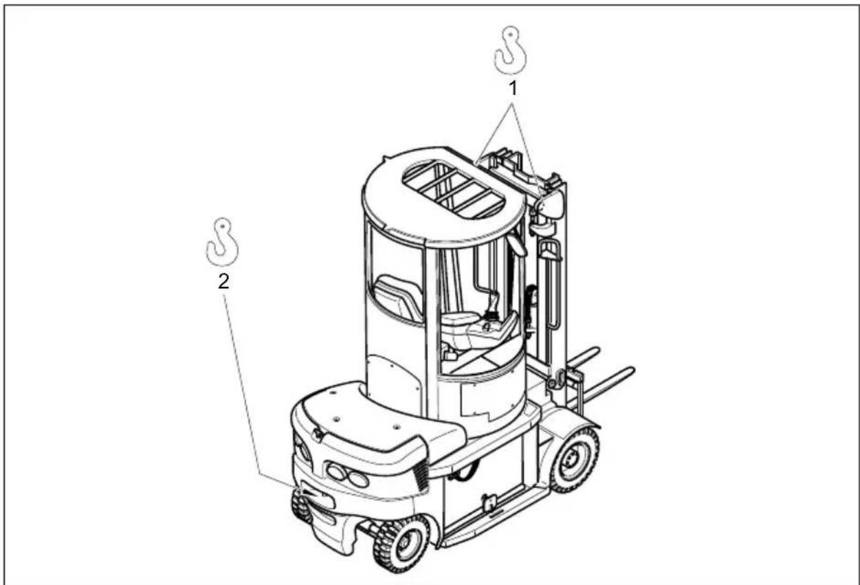
- Attach the crane slings to the cross member of the mast (1) and the trailer coupling (2).
text_image
Technical diagram of a forklift with labeled parts 1 and 2, showing internal components and assembly lines.
Loading by crane is only intended for when the truck is being transported for the first time.
If the truck is being used in different locations, requiring constant loading, please consult with the manufacturer.

Only suspend crane belts/chains to the top eye of the counterbalance weight and the eyes of the upper cross member (mast).
The mast must be tilted back fully.
The crane belt or the chain on the mast must be at least 2m long.

Lifting slings should be fastened to the harness in such a way that they do not come into contact with any attachments or the overhead guard when it is being raised.
2 S e c u r i n g t h e t

The truck must be securely fastened when being transported on a lorry or a trailer. The lorry / trailer must have fastening rings and a wooden floor. Loading must be carried out by specially trained staff in accordance with recommendations contained in Guidelines VDI 2700 and VDI 2703. In each case correct measurements shall be determined and appropriate safety measures adopted.

To secure the truck with the mast assembled, use the eyes on the upper cross member of the mast and the trailer pins.
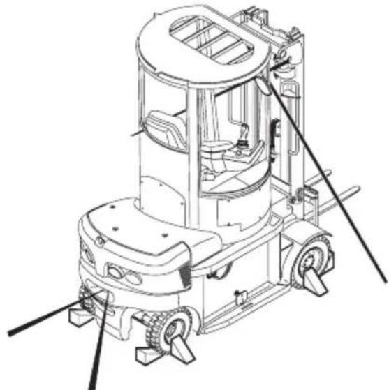
natural_image
Technical line drawing of a forklift with visible gears and mounting brackets (no text or symbols)Securing and fastening the truck with mast assembled

If the truck is to be transported without a mast, it must be fastened at the front via the front wheels.
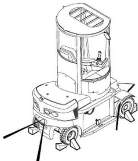
natural_image
Technical line drawing of a robotic vacuum cleaner with wheels and control panel (no text or symbols)Securing and fastening the truck without a mast
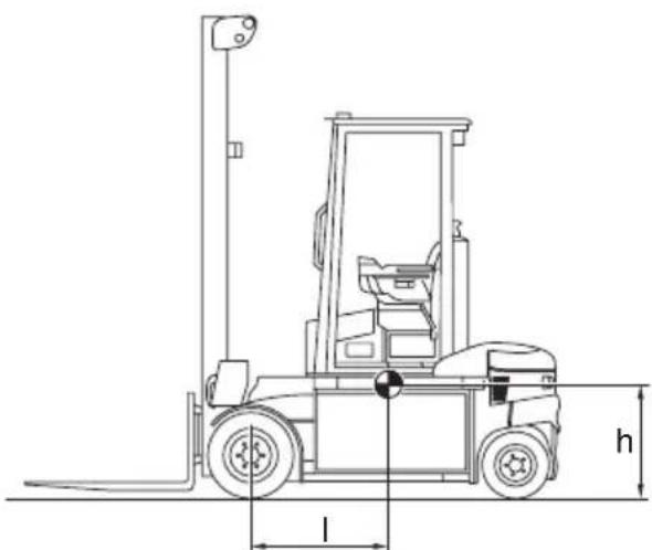
natural_image
Technical line drawing of a forklift with height dimension labeled 'h' and base length 'l' (no text or symbols beyond basic geometry)Approximate centre of gravity position
3 Using the truck for the first time

Commissioning and driver instruction must be performed by trained personnel. If several trucks have been delivered, make sure that always the serial numbers of the load lifting devices, masts and basic trucks match each other.

Only operate the truck with battery current. Rectified AC current will damage the electronic components. The battery leads (tow cables) must be less than 6m long.
To prepare the truck after delivery or after transport, proceed as follows:
- Check all the equipm
- Check the battery co acid level (see Chapter D).
- Start up the truck as (see Chapter E).
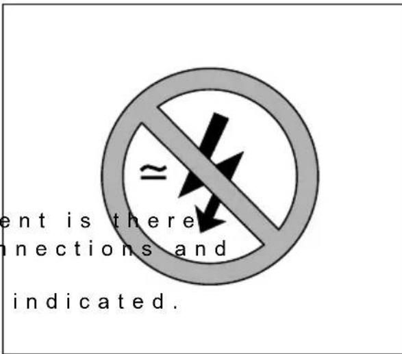
text_image
ent is there connections and indicated.4 O p e r a t i n g t h e
To move the truck without a power supply, the spring-loaded accumulator brake must be released as follows:

Before releasing the brake, take appropriate measures to prevent the truck from rolling away.
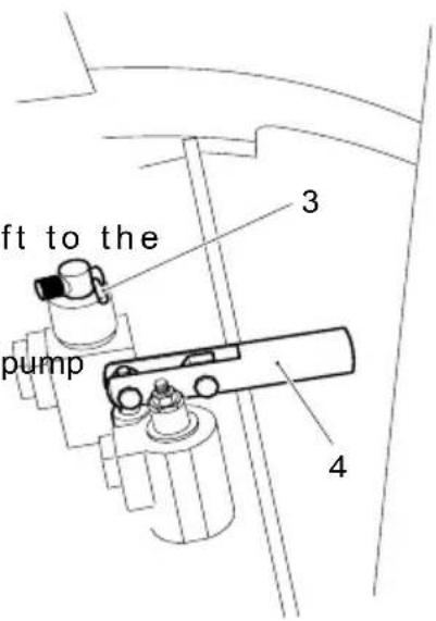
- Move the lever (3) to the left to the "release spring-loaded accumulator brake" position.
- Carry out a sufficient number of pump strokes with the lever (4) until pressure builds up in the hydraulic circuit and the spring-loaded accumulator brake is released. The drive wheels are no longer blocked / braked by the spring-loaded brake. The foot brake does not work without energy or if the truck is switched off.

Before starting the truck again with power supply, the lever (3) must be reset to the right in the "travel" position. The truck can only operate in the travel position.
text_image
ft to the pump 3 45 S t e e r i n g t h e t l

The truck cannot be steered if the hydraulic system is damaged.

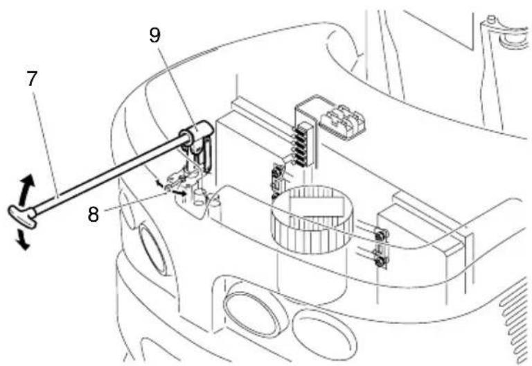
To steer the truck without power supply, manually apply the emergency steering pump.
- Unscrew the 3 screws (5) screws from the side of the rotating cab. Now remove the panel (6).

text_image
5 6 and 2 7) from the- Remove the tow mandrel (7) from the truck receptacle.
text_image
Technical diagram of a mechanical assembly with numbered components and directional arrows indicating motion or assembly.- Fit the tow mandrel (7) in the emergency steering pump receptacle (9).
- Move the lever (8) in the appropriate direction.
- Move the tow mandrel (7) up and down to obtain the required steering angle.

On reaching the truck's limit position, the lever (8) must be reset to its centre position.
6 T o w i n g a n d l i f
- Attach the tow bar / rope to the trailer coupling of the recovery vehicle and the truck to be recovered.
- Remove the battery connector (note item D3).
- Release the parking brake (as described in item 4):
- Steer (as described in item 5):
D Battery Maintenance
1 S a f e t y r e g u l a t
Park the truck securely before carrying out any work on the batteries (see Chapter E).
Maintenance personnel: Batteries may only be charged, serviced or replaced by trained personnel. The present operating instructions and the manufacturer's regulations concerning batteries and charging stations must be observed when carrying out the work.
Fire protection: Smoking and naked flames must be avoided when working with batteries Wherever a truck is parked for charging there shall be no inflammable material or operating fluids capable of creating sparks within 2 metres around the truck. The area must be well ventilated. Fire protection equipment must be provided.
Battery maintenance: The battery cell covers must be kept dry and clean. The terminals and cable shoes must be clean, secure and have a light coating of dielectric grease. Batteries with non insulated terminals must be covered with a non slip insulation mat.
Battery Disposal: Batteries may only be disposed of in accordance with national environmental protection regulations or disposal laws. The manufacturer's disposal instructions must be followed.

Before closing the battery cover make sure that the battery lead cannot be damaged.
Batteries contain an acid solution which is poisonous and corrosive. Therefore, always wear protective clothing and eye protection when carrying out work on batteries. Above all avoid any contact with battery acid.
Nevertheless, should clothing, skin or eyes come in contact with acid the affected parts should be rinsed with plenty of clean water - where the skin or eyes are affected call a doctor immediately. Immediately neutralise any spilled battery acid.

Only batteries with a sealed battery container may be used.
The weight and dimensions of the battery have considerable affect on the operational safety of the truck. Battery equipment may only be replaced with the agreement of the manufacturer.
2 B a t t e r y t y p e s
The truck will be equipped with different battery types, depending on the application. The following table shows which combinations are included as standard:
| EFG-D30 | 80 V - 5PzW - 540 Ah |
| 80 V - 6PzS - 540 L |
The battery weight is indicated on the battery data plate.

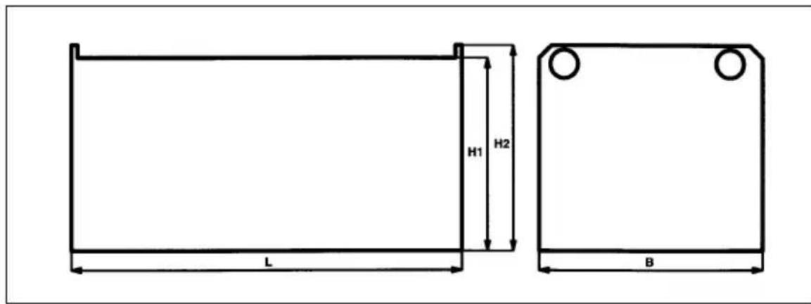
The weight and dimensions of the battery have a considerable affect on the operational safety of the truck. The size and weight of the batteries must therefore comply with the following table and diagram. The truck can only be operated with different batteries with the manufacturer's authorisation.
| Drive battery 80 volts | Similar to DIN 43536 | |||||
| Truck | Dimension (mm) Rated weight | (-5/+8%) in kg | ||||
| L max. W | max. H1 +/- | 2 mm H2 +/- | 2 mm | |||
| EFG-D30 10 | 28 998 517 | 537 1445 | 540 -590 Ah | |||
text_image
H1 H2 L B3 E x p o s i n g t h e b

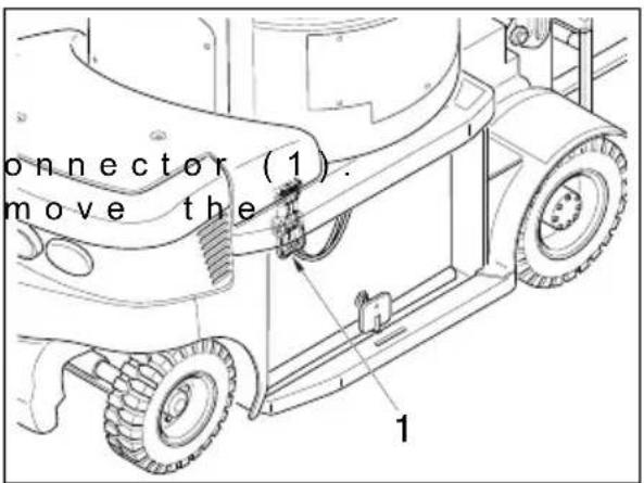
Always connect and disconnect the battery connector and the socket when the mains and charger are switched off.
- Remove the battery c - Where necessary re insulating mat from the battery.
text_image
connector (1). move the 14 C h a r g i n g t h e b
-Expose the battery (see Chapter D).

Always connect and disconnect the battery and the charger when the charger and truck are switched off.
When charging, the tops of the battery cells must be exposed to provide sufficient ventilation. Do not place any metal objects on the battery.

Before charging, check all cables and plug connections for visible signs of damage.
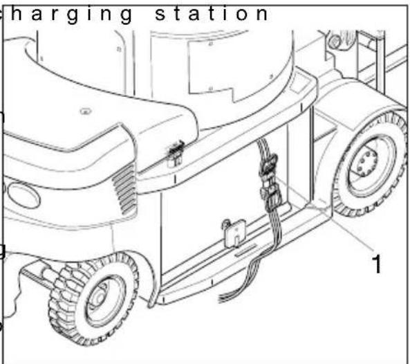
- Connect the battery cable to the battery connector (1). - Switch on the battery charging station and charge the battery in accordance with the battery and charging station manufacturers' instructions.

It is essential to follow the safety regulations of the battery and charging station manufacturers. The side openings must never be sealed as they allow gas produced during charging to escape. Do not use fire or naked flames. Explosion hazard!
text_image
harging station 1
To prevent short circuits, batteries with exposed terminals or connectors must be covered with a rubber mat. When replacing a battery with a crane, make sure the crane has sufficient capacity (see battery weight on the battery data plate on the container). The lifting gear must exert a vertical pull so that the battery container is not compressed. Hooks must be fitted in such a way that when the crane lifting harness is slackened, they do not fall onto the battery cells.
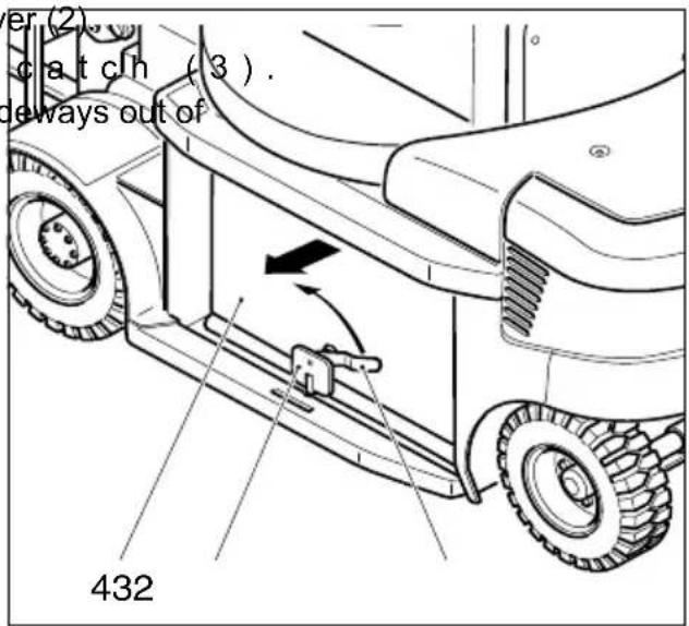
- Loosen the locking lever (2). - Remove the battery catch (3). - Pull the battery (4) sideways out of the truck.
text_image
er (2). catch (3). deways out of 432Assembly is the reverse order.

When replacing a battery always use the same battery type. After installing the battery again, check all cables and plug connections for visible signs of damage.
Insert the battery catch (3) in the bushing and jam the locking lever (2). If this does not jam the battery (4), the block on the opposite side must be adjusted.

When replacing/installing the battery make sure the battery is securely located in the battery compartment of the truck.
5.1 Removal / assembly with a battery trolley

Always replace / assemble batteries when the truck is horizontal.
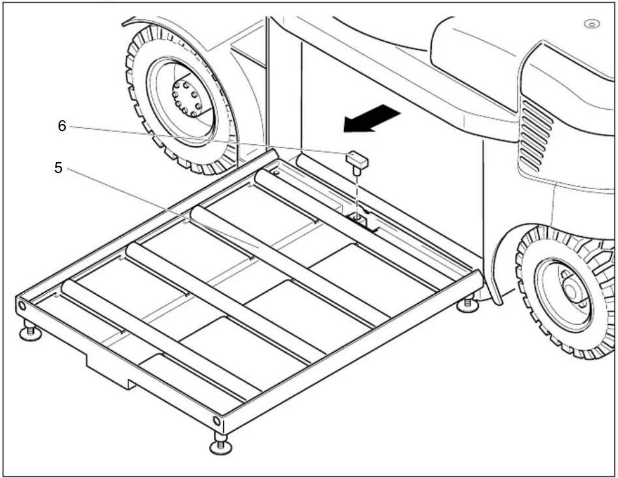
- Attach the battery trolley (5) to the side of the truck.
- Undo the locking lever (2).
- Remove the battery catch (3).
-Pull the battery (4) onto the side of the prepared battery trolley

Secure the battery with retaining bolts (6).
Assembly is the reverse order.
text_image
Technical diagram of a tractor's wheel assembly with numbered parts and an arrow indicating motion direction5.2 Removal / assembly with a battery trolley using a discharge device
STOP
Always replace / assemble batteries when the truck is horizontal.
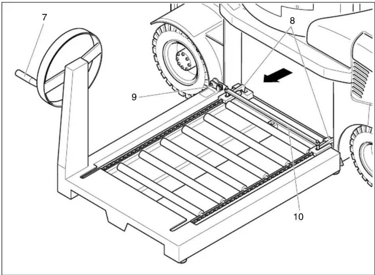
- Bring the battery trolley to the side of the truck.
- Undo the locking lever (2).
- Remove the battery catch (3).
- Move the removal hooks (8) up to the battery by turning the engage them in the corresponding receptacles.
- Pull the battery off the truck onto the trolley by turning opposite direction.
-Turn the battery retainer (9) over and secure the battery
STOP
Move the battery trolley away once the battery has been secured.
Assembly is the reverse order. The removal hooks (8) can be un-hooked by pulling back the rod (10).
text_image
Technical diagram of a mechanical device with numbered components and directional arrow indicating motion or assembly.6 B a t t e r y D i s c h a
Battery Discharge Indicator: The battery charge status is shown in the Information and Service Display.

The standard setting for the battery discharge indicator / discharge monitor is based on standard batteries.
If using maintenance-free batteries, the display must be re-set. This setting must be carried out by the service department. If this adjustment is not made the battery may become damaged through excessive depletion.
When you reach the last remaining 10% capacity, the warning symbol starts to flash.
When a battery is discharged to the permissible discharge level, the battery symbol is displayed empty.
Battery Discharge Monitor: If the residual capacity falls below the required level, lifting is inhibited. A message is shown on the Information and Service Display.
To complete the lifting operation, turn the key switch off and on again. You can then continue to raise for another 30 - 40 seconds.

Lifting is only released when the battery connected is at least 40% charged.
Hourmeter: The service hours are displayed next to the battery charge status. The hourmeter shows the overall travel and lifting time.
E O per a t i o n
1 S a f e t y R e g u l a t
Driver authorisation The forklift truck may only be used by suitably trained personnel, who have demonstrated to the proprietor or his representative that they can drive and handle loads and have been authorised to operate the truck by the proprietor or his representative.
Driver's rights, obligations and responsibilities: The driver must be informed of his duties and responsibilities and be instructed in the operation of the truck and shall be familiar with the operator manual. The driver shall be afforded all due rights. Safety shoes must be worn with pedestrian operated trucks.
Unauthorised Use of Truck: The driver is responsible for the truck during the time it is in use. The drive must prevent unauthorised persons from driving or operating the truck. It is forbidden to carry passengers or lift other people.
Damage and Faults: The supervisor must be immediately informed of any damage or faults to the forklift truck. Trucks which are unsafe for operation (e.g. wheel or brake problems) must not be used until they have been rectified.
Repairs: The driver must not carry out any repairs or alterations to the industrial truck without the necessary training and authorisation to do so. The driver must never disable or adjust safety mechanisms or switches.
Hazardous area: A hazardous area is defined as the area in which a person is at risk due to truck movement, lifting operations, the load handler (e.g. forks or attachments) or the load itself. This also includes areas which can be reached by falling loads or lowering operating equipment.

Unauthorised persons must be kept away from the hazardous area. Where there is danger to personnel, a warning must be sounded with sufficient notice. If unauthorised personnel are still within the hazardous area the truck shall be brought to a halt immediately.
Safety Devices and Warning Signs: Safety devices, warning signs and warning instructions shall be strictly observed.
Make sure there are no objects near the driver's feet that could affect the pedal operation. The ground / floorboard must be cleaned at regular intervals to prevent dirt building up underneath the pedals.
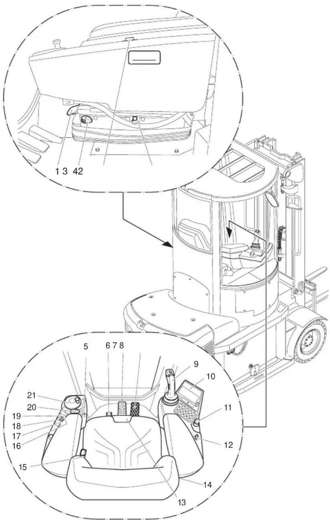
| Item | Control / Display | Function | |
| 1 | H e i g h t | s e t t i n g ● The height can be infini | |
| 2 | L o n g i t cushioning stop | u● | Activates the longitudinal horizontal cushioning. |
| 3 | Left armrest stop | ● | Adjusts the left hand armrest tilt. |
| 4 | L a t e r a cushioning stop | l● | Activates the lateral horizontal cushioning.l |
| 5 | L e f t a adjustment | r | Adjusts the height of the left handiarmresth t |
| 6 | C a b i n | r | o t a t e b u t t o n |
| 7 | B r a k e | p | e d a l ● Applies the load wheel brake |
| 8 Accelerator pedal ● Infinite travel speed control | |||
| 9 | MULTIPILOT | ● | Selects the travel or rotary direction, controls the lift mast functions, issues a warning signal. |
| 10 | Control panel ● Displays the main travel, lift parameters, warning displays, error messages and service displays, as well as battery discharge and elapsed hour display. | ||
| 11 EMERGENCY DISCONNECT | ● | Switches power supply on and off. | |
| 12 | Key switch | ● | Switches control current on and off. Removing the key prevents the truck from being switched on by unauthorised personnel. |
| 13 | Seat tilt / Seat depth adjustor | ● | Adjusts the seat depth setting and the longitudinal tilt |
| 14 | Right armrest stop | Adjusts the right hand armrest tilt. | |
| 15 | Backrestadjustment | ● | Adjusts the backrest. |
| 16 | Programming button cabin position M1 | ● | Press the button for 3 seconds to store the cabin position. |
| 17 | Start button cabin position L1 | ● | The cabin moves to the programmed position M1 |
| 18 | Start button cabin position L2 | ● | The cabin moves to the programmed position M2 |
| 19 | Programming button cabin position M2 | ● | Press the button for 3 seconds to store the cabin position. |
| 20 | Travel direction display switch | ● | Switches on LH/RH indicator |
| 21 | Steering wheel | ● | Steers the truck in the required direction. |
| ● = Standard equipment ○ = Optional Equipment | |||
text_image
Technical diagram of a vehicle interior with numbered components and zoomed-in views for identification.3 C o n t r o l p a n e l
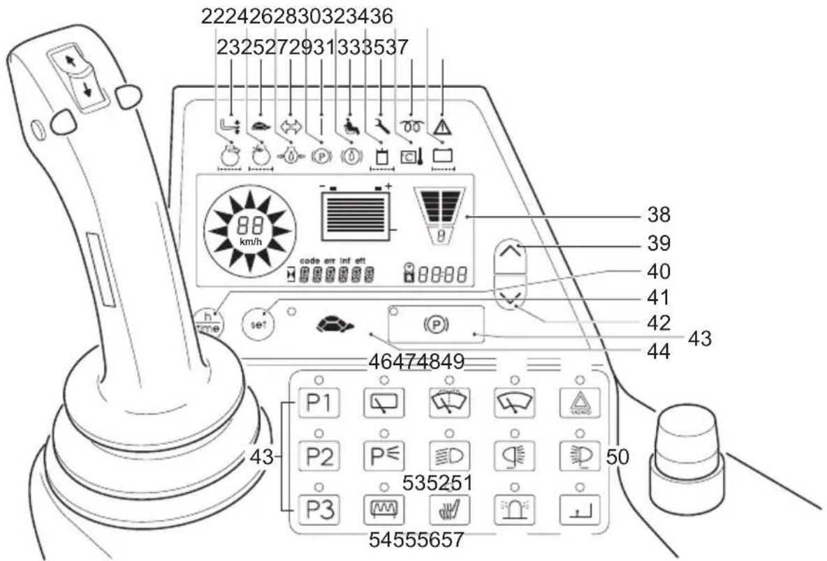
The control panel display shows the operating data, the battery charge, the service hours and error details and information. Graphic illustrations on the control panel act as warning indicators.
text_image
2224262830323436 2325272931333537 88 km/h code err inf ett h* se* 38 39 40 41 42 43 44 46474849 P1 P2 P3 535251 54555657 503.1 Control panel displays
| Item Display | |
| 22 No function | |
| 23 No function | |
| 24 No function | |
| 25 Cravel speed control light | |
| 26 No function | |
| 27 | Travel direction indicator- For lighting with a flashing indicator system |
| 28 | Parking brake applied-Truck operational, parking brake applied |
| 29 | Truck operational- Keys switch ON |
| Item Display | ||
| 30 No function | ||
| 31 | [04C] | Seat switch- Seat switch not closed- Truck operational, but driver's seat not occupied |
| 32 No function | ||
| 33 |  | Service Display- Service interval exceeded (1000 service hours) or annual UVV test due (flashing indicator). |
| 34 | [2D7T] | Controller overtemperature-Lights up for controller overtemperature- Performance continually reduces with respect to the temperature |
| 35 No function | ||
36 No  | ||
| 37 |  | WARNING-Lights up for errors- Flashes when battery capacity is less than |
| 38 Driver's display | ||
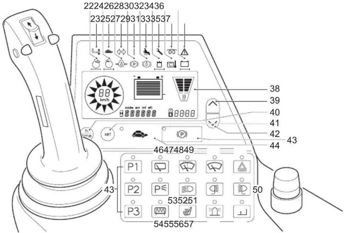
3.2 Control panel buttons
text_image
2224262830323436 2325272931333537 88 km/h code url int eff h time set P1 P2 P3 535251 54555657 38 39 40 41 42 43 44 46474849 50| Item Function | ||
| 39 Se |  | travel program (go up to other modes) |
| 40 Hc |  | ter / time toggle switch |
| 41 |  | SET button- Selects special functions |
| 42 Se |  | travel program (go down to other modes) |
| 43 |  | Parking brakeApplies / releases parking brake |
| 44 |  | Crawl speed switch- Travel speed max. 6 km/h (adjustabl |
| 45 OI |  | oid |
| 46 S |  | roof window wipers on and off, interval setting |
| 47 S |  | windscreen wiper system on and off. |
| 48 S |  | window wipers on and off, interval setting |
| 49 | Switches | warning indicator system on and off. |
| 50 | Switches | front headlights on and off. |
| 51 | Switches | rear headlights on and off. |
| 52 | Switches | dipped lights on and off. |
| 53 | Switches | parking light on and off. |
| 54 | Switches | rear window heating on and off. |
| 55 | Switches | seat heating on and off. |
| 56 | Switches | the beacon on and off. |
| 57 | “Lift cutout” | override button |
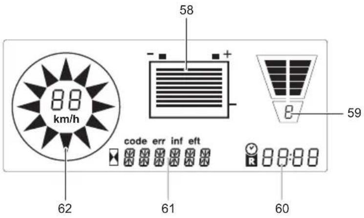
Displays
text_image
88 km/h 62 58 - + code err inf eft 61 59 R 88:88 60| Item Function |
| 58 Battery capacity display– Battery discharge status |
| 59 Profile number (travel / lift profile 1, 2, 3, 4 and 5) |
| 60 Hourmeter display– Time display– Displays the residual time with the onboard battery (hours : minutes). |
| 61 Error display:– if an error (Err) or a warning (Inf) occurs, the operating hour display disappears.– If several errors occur they are displayed alternately at 1.5 seconds. A warning signal sounds.– eft: shows the overall working time |
| 62 Travel direction, speed and wheel position display– Indicates the pre-selected travel direction (forward or reverse) or the position of the steered wheels. |
Setting the time
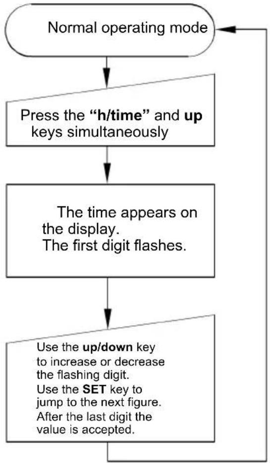
flowchart
graph TD
    A["Normal operating mode"] --> B["Press the "h/time" and up keys simultaneously"]
    B --> C["The time appears on the display.<br>The first digit flashes."]
    C --> D["Use the up/down key to increase or decrease the flashing digit.<br>Use the SET key to jump to the next figure.<br>After the last digit the value is accepted."]
    D --> E
3.3 Driver's Display Warning Messages
| Display Meaning | |
| INFO 02 - No | direction selected when truck powered up, no wheel position displayed-Travel direction changed to neutral setting during operation, wheel position display alternates between forward and reverse. |
| INFO 05 (Opt | onal setting for travel cutout input)Lift cutout active / independent of other conditions |
| INFO 16 (Opt | onal setting for travel cutout input)Travel cutout active / independent of other conditions |
| INFO 18 Safety | ty height exceeded-Load handler above 300mm and cabin between 90° and 180° position, travel disabled.Rotate cabin to 90°, lower load handler. Travel enabled in 180° position. |
| INFO 22 Inf 22 | (no steering) appears and the seat switch LED flashes when the seat is occupied and the armrest tilted. Travel disabled. |
| INFO 35 Accelerator pedal zero position | -Message can be adjusted to suit preference – either the zero position is only checked after power up or after every transition of the seat switch from the open to closed position.-Message appears if the cabin is to be rotated from 90° to 180° (or vice versa) and the accelerator pedal is not in the zero position. |
| INFO 36 Hydr | aulics zero position-Message can be adjusted to suit preference - message displayed or not. |
| INFO 40 Over | temperatureTraction or lift controller above 83°C.Traction or lift controller above 145 °C. |
| INFO 96 Hydr | aulics zero position on power up-a hydraulic function applied during power up-the hydraulic function applied will not be performed. |
4 S t a r t i n g u p t h

Before commissioning or operating the truck, and before raising a load, the driver must ensure that there is nobody in the hazardous area and that the truck is safe to operate.

Before the cabin can be moved, the driver must ensure that nobody is within range and that nobody has their hands in or on the cabin when the cabin is rotated. Access forbidden between the mast and overhead guard/cabin!
4.1 Checks and operations to be performed before starting daily work
Before starting the truck the driver must ensure it is safe to operate. Before starting work, check that
– the operating and parking brakes or the automatic brake (Emergency Stop) are working
- the fork tine retainer preventing the tines from moving is not defective
- the load handler does not show visible signs of damage (bent, cracks or heavy wear)
-the warning device is working
- Notice: check battery latch before driving
4.2 Entering the truck

You can enter the truck from either side via the front cover and the stepboards on the mudguards.
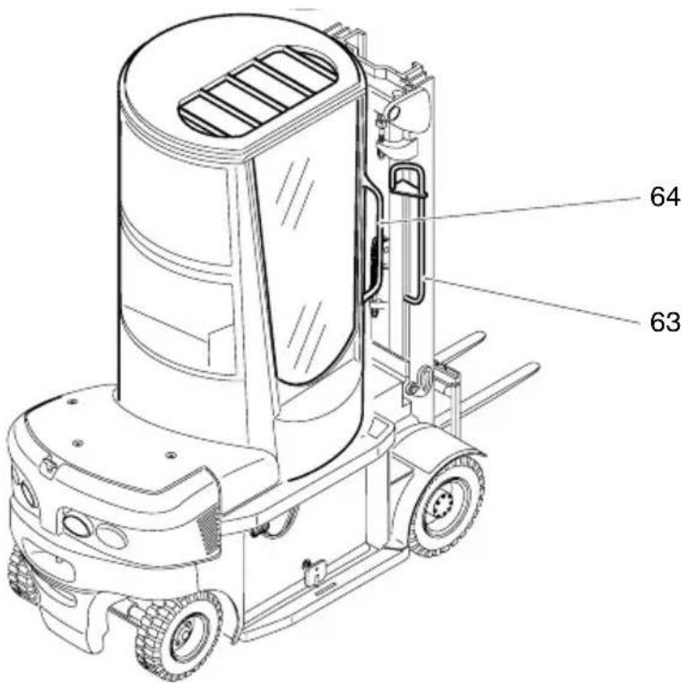
text_image
64 63- Use the handles or and on the A column (63).
- Close the sliding necessary undo the door lock.

If the door is open or if there is an open gap, the door must always be locked. This is the purpose of the locking lever at the top of the door.
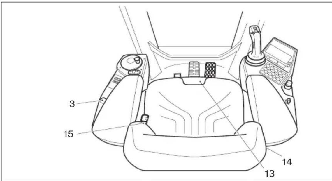
- Press the button (3) to move the left armrest in the required position, otherwise the steering wheel cannot be operated.
- Travelling is inh armrest is moved all the way down.
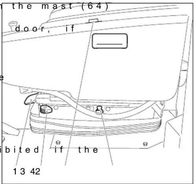
text_image
the mast (64) door, if bited if the 1 3 424.3 Adjusting the driver's seat

To achieve optimal seat cushioning the driver's seat must be adjusted to suit the driver's weight before starting the truck.
The driver must sit on the seat to adjust it.
Adjusting the driver's weight:
- Pull the actuation briefly in the direction of the arrow.
Height adjustment
- Pull / push the ac (1) in/out fully until you reach the desired height.
Longitudinal horizontal cushioning
- Push lever (2) on the seat backwards. Longitudinal horizontal cushioning is active.
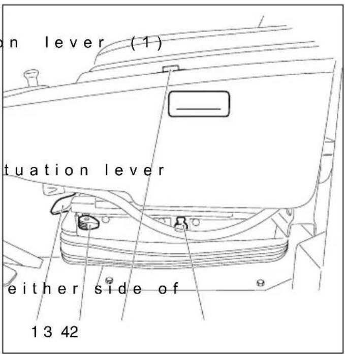
text_image
on lever (1) tuation lever either side of 13 42Lateral horizontal cushioning
– Pull lever (4) forward. Lateral horizontal cushioning is active.
Seat tilt adjustment
– Pull the actuation lever (13) on the left and sit on or off the seat. The seat will now be inclined to the desired position.
Seat depth adjustment
– Pull the actuation lever (13) on the right and push the seat forward or backwards until the seat reaches the desired position.

The driver's seat must be securely engaged in the set position. The driver's seat setting must not be changed during travel.
LH armrest tilt
- Press button (3) to move the armrest in the desired position.
RH armrest tilt
Turn the knob (14) until you reach the desired position.
Backrest tilt
- Apply the lever (15) to set the backrest to the desired position.

The procedure for adjusting the driver's seat applies to standard models. For other models, follow the manufacturer's setting instructions. When adjusting, ensure that all controls are within easy reach.
text_image
3 15 14 134.4 Safety restraint belt

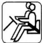
Put on the safety restraint belt each time before starting the industrial truck. The belt protects against serious injury.
Protect the belt from contamination (e.g. cover it when the truck is idle) and clean it regularly. Frozen belt locks or pulleys must be thawed out and dried to prevent them from freezing up again.

The dry temperature of the warm air should not exceed +60°C.

Do not alter the belt setting. This will increase the risk of malfunctioning.
- Always replace the safety restraint belt after an accident. - Only original spare parts must be used for retrofits or repairs.

Damaged or non-operational belts must be replaced by the local Jungheinrich branch.
Procedure in unusual situations

If the truck is about to tip over, never undo the restraint belt and try to jump out.
This will only increase the risk of injury.
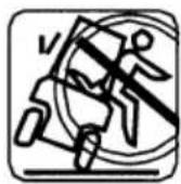
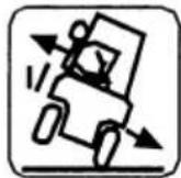
Correct procedure:
- Tilt your upper body forward. - Hold on to the controls (Multipilot and on the armrest) with both hands and brace your feet.
- Lean your body in the opposite direction of fall

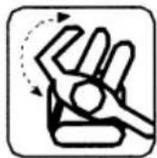
Restraint belt instructions
Before starting the truck pull the belt out of the pulley, pull it tightly across your body and engage it in the lock.

The belt must not be twisted when fastened.
When operating the truck (e.g. travelling, lifting, lowering, etc.), sit as far back as possible so that your back is against the backrest.
The automatic locking retractor allows sufficient freedom of movement on the seat.

If you sit on the front edge of the seat there is less protection afforded as the belt is too long.

The belt is only to be used to secure one person..
- After using the belt, push the red button and manually guide the tongue back to the retractor.

The automatic blocking system can be triggered if the seat belt tongue strikes the housing. This will prevent the belt from being extracted.
Deactivating the blocking system:
- Apply force to pull the belt 10mm - 15mm out of its housing.
- Feed the belt back in to undo the automatic blocking system.
The belt can now be extracted again.
Starting the industrial truck on steep slopes
The automatic blocking system locks the belt in the retractor when the truck is positioned on a steep slope. This prevents the belt from being pulled out of the retractor.

Carefully drive the truck off the slope and then put on the belt.


4.5 To prepare the truck for operation
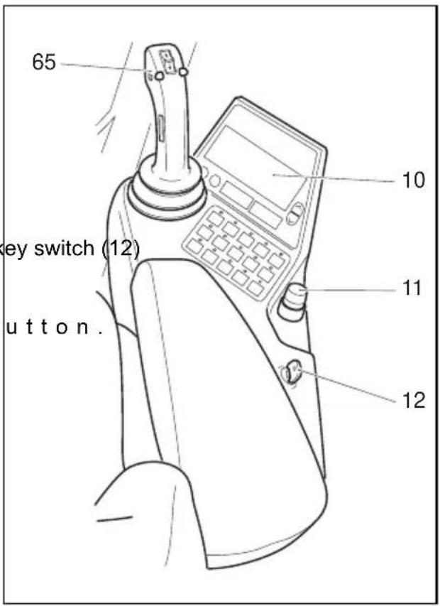
- Unlock the EMERGENCY DISCONNECT switch (11). To do this: Turn and pull the switch up (↑) until you can feel the EMERGENCY DISCONNECT switch (11) engaging.
- Insert the key in the and turn it clockwise as far as it will go to the "I" position.
- Test the horn (65) b

Test the electric parking brake.
The truck is now operational.

The control panel (10) indicates the available battery capacity.
text_image
65 key switch (12) utton. 10 11 12
When you have pulled the EMERGENCY DISCONNECT and turned the key switch to the right, the truck carries out a self test for approx. 3-4 seconds (tests the electronic system). During this time the truck cannot move. If the accelerator pedal is applied during this time, the display will show "Zero drive sens".
5.1 Safety regulations for truck operation
Travel routes and work areas: Only use lanes and routes specifically designated for truck traffic. Unauthorised third parties must stay away from work areas. Loads must only be stored in places specially designated for this purpose.
Driving conduct: The driver must adapt the travel speed to local conditions. The truck must be driven at slow speed when negotiating bends or narrow passageways, when passing through swing doors and at blind spots. The driver must always observe an adequate braking distance between the forklift truck and the vehicle in front and must be in control of the truck at all times. Abrupt stopping (except in emergencies), rapid U turns and overtaking at dangerous or blind spots are not permitted. It is forbidden to lean out of or reach beyond the working and operating area.
Travel visibility: The driver must look in the direction of travel and must always have a clear view of the route ahead. Loads that affect visibility must be positioned at the rear of the truck. If this is not possible, a second person must walk in front of the truck as a lookout.
Negotiating slopes and inclines: Negotiating slopes or inclines is only permitted if such roads are clean and have a non-slip surface and providing such journeys are safely undertaken in accordance with the technical specifications for the truck in question. The truck must always be driven with the load unit facing uphill. The industrial truck must not be turned, operated at an angle or parked on inclines or slopes. Inclines must only be negotiated at slow speed, with the driver ready to brake at any moment.
Negotiating lifts and docks: Lifts and docks must only be used if they have sufficient capacity, are suitable for driving on and authorised for truck traffic by the owner. The driver must satisfy himself of the above before entering these areas. The truck must enter lifts with the load in front and must take up a position which does not allow it to come into contact with the walls of the lift shaft. People travelling in the lift with the forklift truck must only enter the lift after the truck has come to a halt and must exit the lift before the truck.
Type of loads to be carried: The driver must ensure that the load unit is in a suitable condition. Only carry properly secured loads. Never transport loads stacked higher than the top of the fork carriage or the load guard.
Towing trailers or the truck itself being towed are only permitted occasionally, on secure, level routes, with a maximum deviation of +/- 1% and at a max. speed of 5 km/h. The truck shall not be permanently used with trailers.
There must be no load on the forks when the truck is being pulled.
Do not exceed the maximum towed load specified for the truck for trailers with or without brakes (see Chapter B). The specified trailer load only applies for the auxiliary coupling in the counterbalance of the forklift. If a different trailer coupling is used on the truck, the instructions of the coupling manufacturer must be observed.
After coupling and before starting the driver shall ensure that the trailer couplir cannot become detached.
Trucks pulling a load must be operated in such a manner that the trailing vehicle is driven safely and can be stopped at all times.
5.2 Travel

Travelling in electromagnetic fields beyond the permitted limits can result in random truck movement.
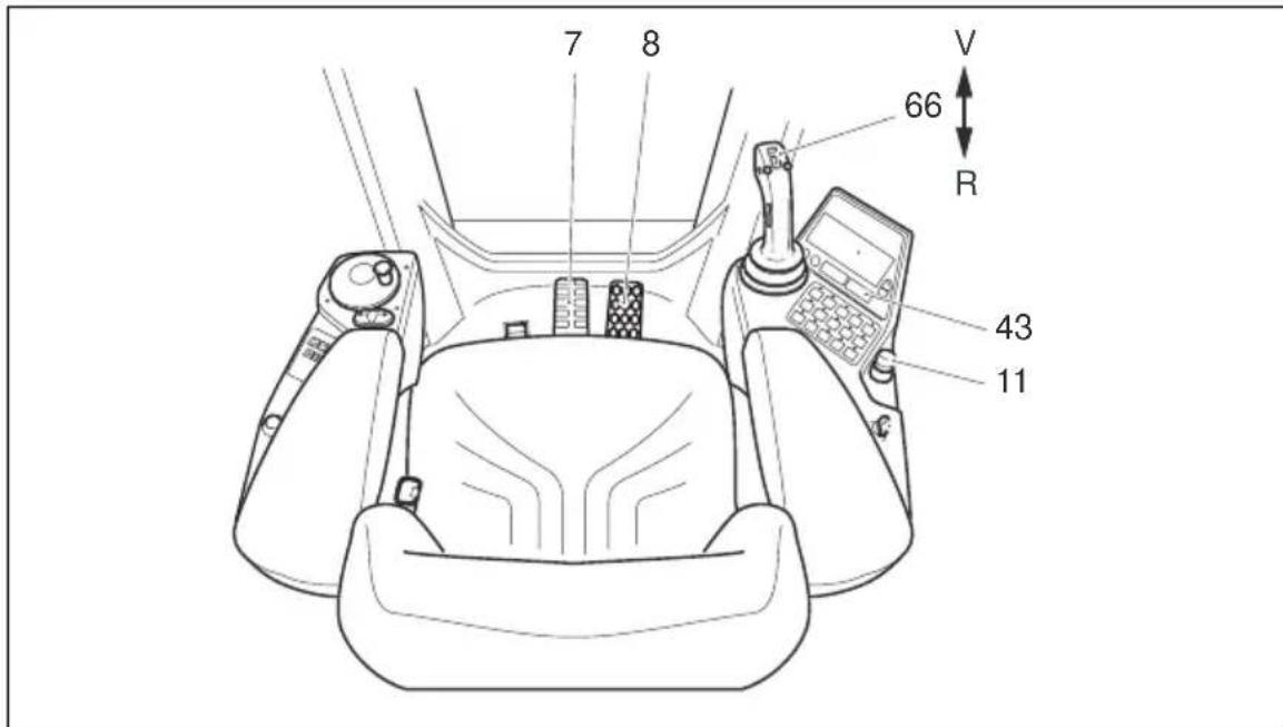
Immediately press the EMERGENCY DISCONNECT (11), apply the service brake and press the brake button (43).
Determine the cause of the fault and if necessary inform the manufacturer's service department.
text_image
7 8 66 R 43 11Safety functions

Travelling is interrupted by the safety switch when the driver's seat is vacant. Occupying the driver's seat and applying the accelerator pedal releases the spring-loaded brake.
The travel speed is reduced as a function of the steering angle. However, the driver is still responsible for adapting the travel speed to the conditions of the travel route, the work area and the load.

Do not drive the truck unless the panels are closed and properly locked.
Travel routes must be free of obstacles.
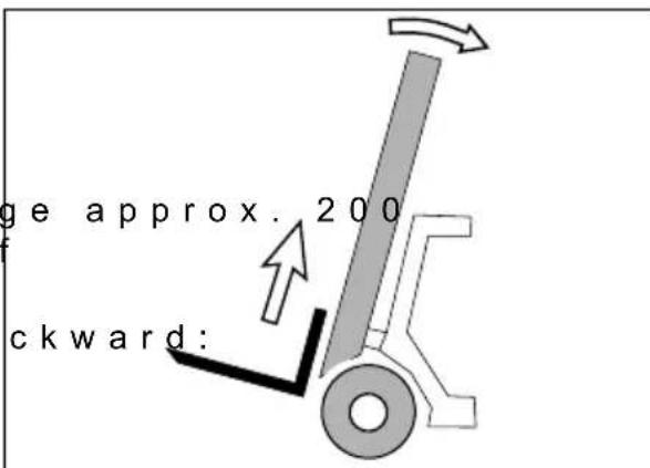
- Raise the fork carriag mm so that the fork tines are clear of the ground.
-Tilt the mast fully ba

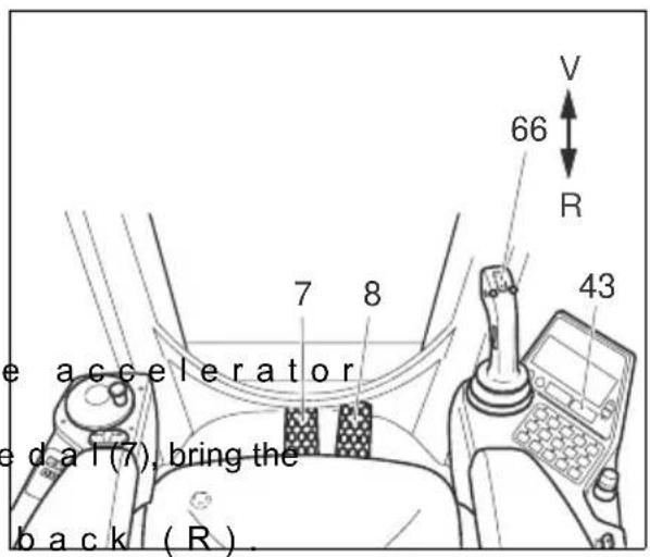
The travel direction can be set using the button (66) on the Multipilot.
text_image
ge approx. 200 ckward:Forward travel

Make sure that the travel area is clear.
- Release the brake button (43).
- Push the button (66) on the Multipilot forward.
-Slowly apply the accelerator pedal (8).

Do not move the Multipilot to travel.

Changing direction
Before setting off in the opposite direction, make sure that the reverse travel area is clear.
- Take your foot off the pedal (8).
- Applying the brake p truck to a halt.
-Push the button (66)
- Slowly apply the accelerator pedal (8) until you reach the required travel speed.
text_image
e accelerator ed at (7), bring the back (R).Accelerating
- Slowly apply the accelerator pedal (8) until the truck starts to move.
- Continue to depress the accelerator (8).
The motor speed and travel speed increase the more you apply the accelerator.

Braking
The braking behaviour depends largely on the ground conditions. The driver must take this into consideration when handling the truck. Brake with care to prevent the load from slipping.
If you are travelling with an attached load you must increase the braking distance.
- Take your foot off the accelerator pedal (8) and if necessary gently apply the brake pedal (7) (see also Section 5.4).

Make sure there are no objects near the driver's feet that could affect the pedal operation. The ground / floorboard must be cleaned at regular intervals to prevent dirt building up underneath the pedals.
5.3 Steering

Very minimal steering effort is required for the electric steering, therefore turn the steering wheel sensitively.
Negotiating right hand bends
- Turn the steering wheel clockwise to match the desired steering radius.
Negotiating left hand bends
- Turn the steering wheel anti-clockwise to match the desired steering radius.
5.4 Braking
There are five ways of braking:
- Service brake
- Coasting brake
- Reversing brake
- Parking brake
- Spring-loaded brake
text_image
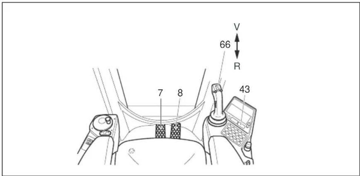
V 66 R 7 8 43Service brake:
-Depress the brake pedal (7).

The service brake acts on the drive wheels regeneratively or hydraulically.
Coasting brake:
- Take your foot off the accelerator pedal (8). The truck brakes regener traction controller.

This operating method reduces energy consumption.
Reversing brake:
- Set the button (66) to the opposite direction while travelling. The truck brakes regeneratively via the traction controller until it starts to travel in the opposite direction.
text_image
V 66 R 7 8 43Parking brake:
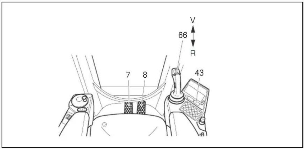
- Apply the brake button (43).

The parking brake acts mechanically on the drive wheels via the multi-plates. There is no sensitive braking.

The parking brake will keep the truck with the maximum permissible load, on a clean ground surface, on a 15% incline.
Spring-loaded brake
The spring-loaded accumulator brake applies approx. 5 seconds (adjustable) after the truck comes to a halt or 1 to 15 seconds (adjustable) after the driver's seat has been vacated.
When you stop on the ramp the truck is held electrically until the spring-loaded brake applies.
When you set off, before the spring-loaded brake is released, a torque builds up on the drive motor to prevent the truck from rolling back.
5.5 Operating the lift mechanism and attachments (Multipilot)

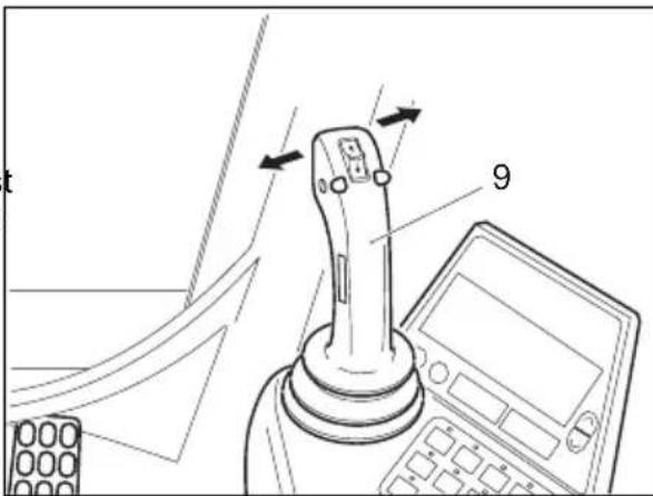
The Multipilot (9) must only be operated from the driver's seat. The driver must be instructed in how to handle the lift mechanism and the attachments.
Push the Multipilot in the desired direction, depending on the hydraulic function.
text_image
Technical diagram showing a mechanical device with labeled parts and directional arrows indicating motion or assembly.Lifting/ lowering the fork carriage
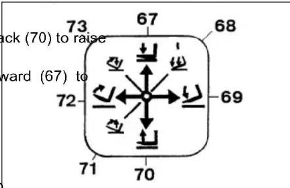
- Move the Multipilot back (70) to raise the fork carriage.
- Move the Multipilot forward (67) to lower the fork carriage.
Tilting the mast forward / backward

When tilting the mast back, ensure no ____ part of your body is between the mast and the front panel.
text_image
ack (70) to raise ward (67) to- Move the Multipilot to the left (72) to tilt the fork carriage back.
- Move the Multipilot to the right (69) to tilt the fork carriage forward.
Twin operation
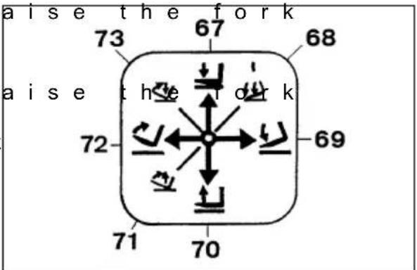
- To simultaneously I carriage and tilt the mast forward, move the Multipilot forward and to the right (68).

text_image
the left (72) to tilt 67 the right (69) to 70 power the fork 72 69- To simultaneously carry and tilt the mast back, move the Multipilot back and to the left (71). - To simultaneously carry and tilt the mast back, move the Multipilot forward and to the left (73).
text_image
aise the fork 73 67 68 aise the fork 72 69 71 70Additional Control (Integrated Sideshift)
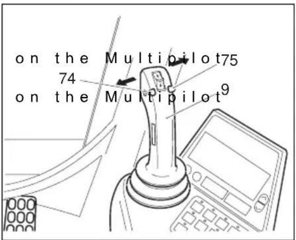
- Press the button (74) to push the fork carriage to the left. - Press the button (75) to push the fork carriage to the right.
text_image
on the Multipilot75 74 on the Multipilot9Rotating the cab
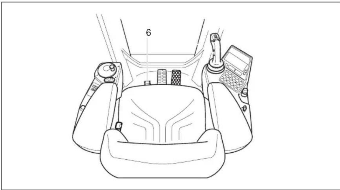
To rotate the cab, move the Multipilot to the right/left while depressing the "cabin rotate" button (6).
natural_image
Line drawing of a car interior with steering wheel, dashboard, and control panel (no text or symbols)Controlling the speed of the lifting device
You control the hydraulic cylinder speed by moving the Multipilot.
When the Multipilot is released it automatically reverts to neutral and the lifting device remains in the position it has reached.

Always apply the Multipilot sensitively, never with a sudden jerk. Release the Multipilot as soon as the lifting device reaches its limit position.

Do not lift other people with the lifting device.
text_image
Prohibition sign with pictogram of a person without a circle and a small dot, indicating no smoking or anti-smoking.5.6 Collecting, transporting and depositing loads

Before picking up a load, the driver must ensure that it is correctly palletised and that the capacity of the truck is not exceeded.
Note the load diagram

Lifting and lowering are inhibited when the cabin is in the 180^ position.
Adjusting the forks

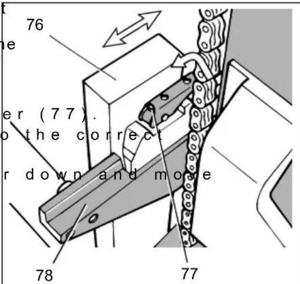
Adjust the fork tines in such a way that both are equally distanced from the outer edge of the fork carriage and the load centre of gravity lies in the middle of the fork tines.
-Raise the locking lev
- Push the forks (76) to position on the fork carriage (78).
- Turn the locking leve the fork time until it engages in a slot.
Raising a load
- Carefully approach th raised.
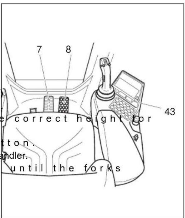
- Apply the brake button (43)
text_image
76 e er (77). to the correct r down and move 78 77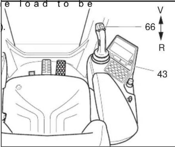
text_image
e load to be 66 R 43 V- Set the mast vertical
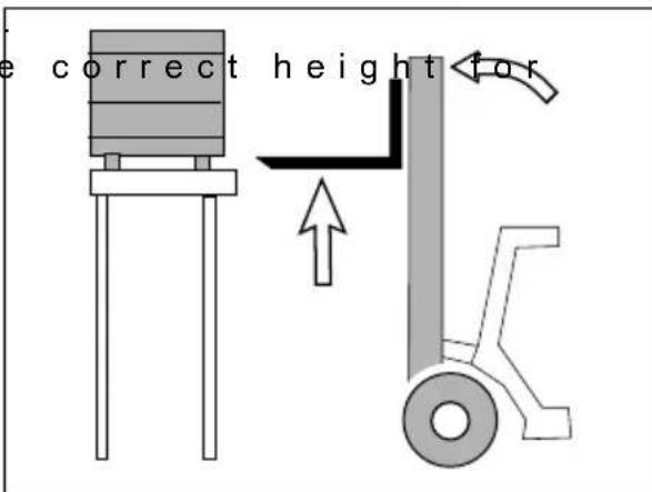
- Raise the forks to the load.
text_image
e correct height for
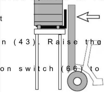
- Drive the truck with forks spread as far apart as possible underneath the load.
At least two thirds of their length must extend into the load. - Apply the brake butto fork carriage until the load rests freely on the forks.
- Set the travel directi reverse and release the parking brake.
orks spread as far
text_image
t n (43). Raise the on switch (66) to
Make sure you have enough space to reverse into.
- Reverse carefully and slowly until the load is outside the storage area.

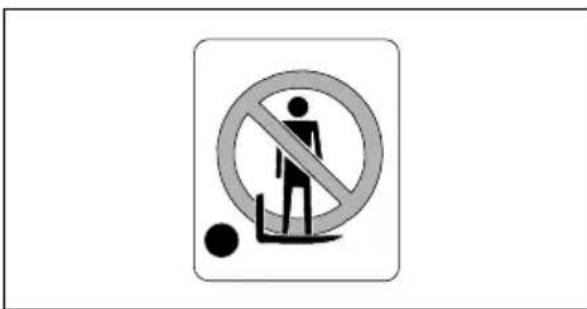
Do not stand underneath a raised load. Never reach through the mast!
- Tilt the mast fully ba - Lower the load as far necessary for transport (ground clearance approx. 150...200 mm).

When transporting loads, the mast must be tilted back and the forks lowered as far as possible.
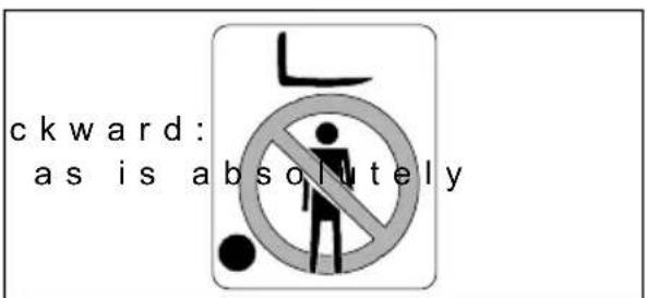
text_image
ckward: as is absolutely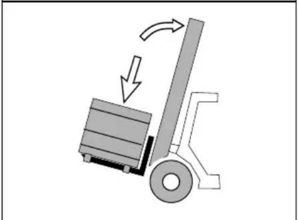
natural_image
Diagram of a forklift lifting a truck, showing motion direction (no text or symbols)Transporting a load

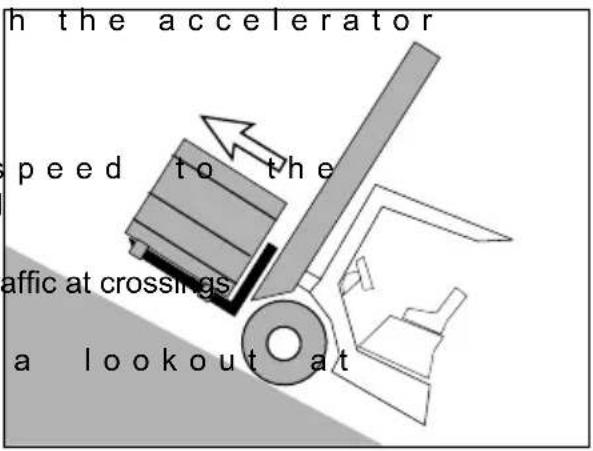
If the load is stacked so high that it affects forward visibility, then reverse.
- Gently accelerate with pedal (8) and slowly brake with the brake pedal (7). Be ready to brake at all times.
- Adapt your travel conditions of the route and the load you are transporting.
- Watch out for other tr and passageways.
- Always travel with blindspots.
text_image
h the accelerator speed to the affic at crossings a lookout at
On slopes and inclines always carry the load facing uphill, never approach at an angle or turn.
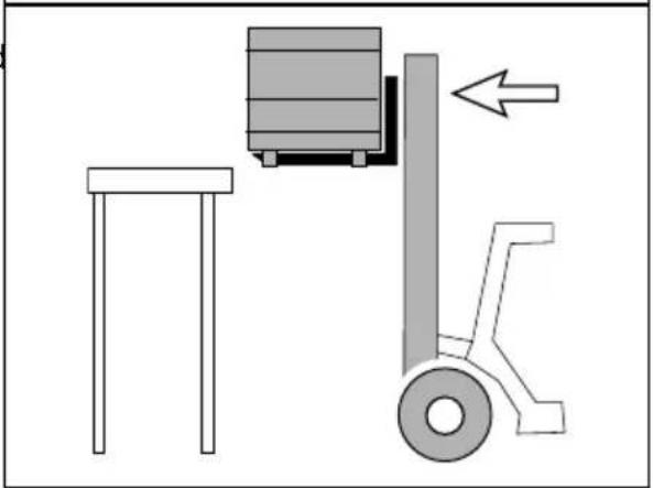
Depositing a load
- Drive the truck carefully up to the load handler.
- Apply the brake button (43)
- Set the mast vertical
- Raise the forks to the the load handler.
- Release the brake button
- Carefully enter the load handler.
- Slowly lower the load are free.
text_image
7 8 e correct height for ton. andler. until the forks 43
Avoid depositing the load suddenly to avoid damaging the load and the load handler.

You can only tilt forward when the load handler is raised in front of or above the stack.
natural_image
Diagram of a mechanical lifting device with a side table and load, showing no text or symbols5.7 Park the truck securely

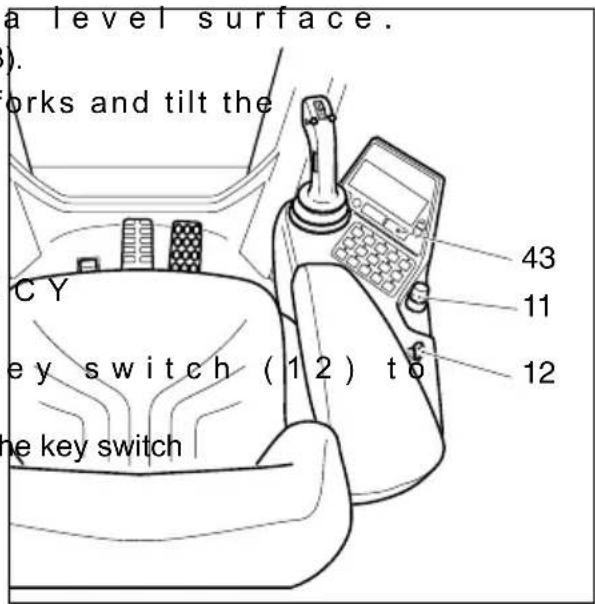
When you leave the truck it must be securely parked even if you only intend to leave it for a short time.
-Drive the truck onto a level surface.
- Apply the brake button (43).
-Fully lower the load forks and tilt the mast forward.

Never park and abandon a truck with a raised load.
- Press the EMERGEN DISCONNECT switch (11) down.
-Turn the key in the k "0".
- Remove the key from th (12).

Avoid parking the truck for long periods of time in areas below 15 °C, as this will render the hydraulic fluids extremely
viscous and consequently the hydraulic functions harder to operate.
Never operate a cold pump at full speed. Heat up the oil by repeatedly tilting and/or lifting slowly.
The LCD display may fail temporarily. As the temperature rises the display will appear again.
text_image
a level surface. works and tilt the CY ey switch (12) to the key switch 43 11 125.8 Leaving the truck
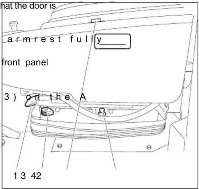
- Rotate the cab so facing forward (towards the mast).
- Push the left hand down using the button (3).
- Exit the cab via the and the stepboard on the mudguard.
- Use the handles (6 column and the mast (64).
text_image
at the door is arm rest fully_ front panel 3) on the A 1 3 42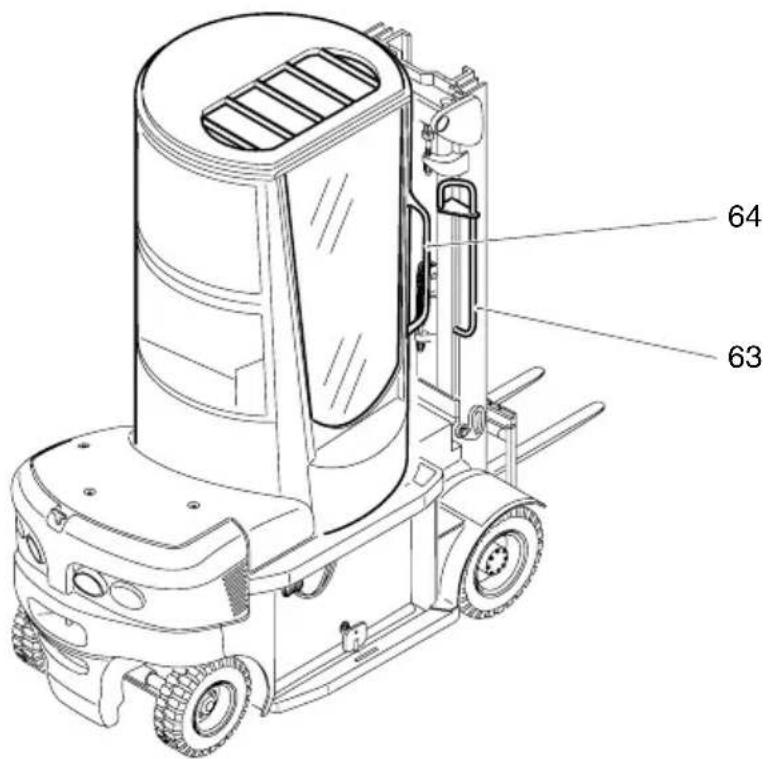
text_image
64 635.9 Towing trailers
The truck can occasionally be used to tow a light trailer on a dry, level and well maintained surface.

The max. tow load is the capacity indicated on the capacity data plate (see decals diagram in chapter B).
The tow load consists of the weight of the trailer and the stated capacity.
If a load is transported on the forks, the tow load must be reduced by the same amount.

Important notes for safe towing
– A truck must not be continually operated with trailers.
- No supporting loads are permitted.
- The maximum speed is 5 km/h.
- Towing must only be performed on level, secure travel routes.
– Follow the instructions of the coupling manufacturer if using special trailer couplings.
- The owner must test trailer operation with the permissible tow load by means of a trial run under the applicable operating conditions in the field.
Attaching the trailer
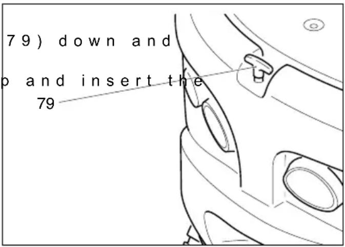
- Push the tow pin (turn it 90 degrees.
- Pull the tow pin u tiller of the trailer vehicle into the opening.
– Insert the tow pin, push it down, turn it 90 degrees and engage it.
text_image
79) down and o and insert the 795.10 Tow loads

Before coupling, the driver must ensure the maximum trailer load is not exceeded.
This chapter is designed to help the user identify and rectify basic faults or the results of incorrect operation. When locating a fault, proceed in the order shown in the table.
| Fault Possible cause Action | |
| Truck does not move | - Battery con not connected- EMERGEN DISCONNECT switch pressed- Key switch in "0" position- Left hand tilt- Battery lock nob not in battery locking bushing- Seat swit unoccupied- Battery ch too low- Faulty fuse - Check fuses |
| Load cannot be lifted | - Truck not operational- Hydraulic too low- Faulty fuse - Check fuses- Battery ch low- Press EMERGENCY DISC or turn key switch to 0, power up the truck andrafter approx. 3 seconds try to perform the desired operation again |
| Error message displayed | - Truck not operational- Software er |

If the fault cannot be rectified after carrying out the remedial procedure, notify the manufacturer's service department, as any further troubleshooting can only be performed by specially trained and qualified service personnel.
6.1 Additional Functions
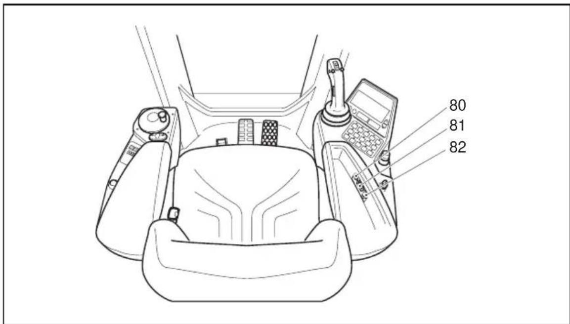
The right hand armrest storage compartment contains a socket for the service connector (81), a socket for the mobile phone charger (82) and the corresponding fuse (80).
text_image
80 81 82F Truck Maintenan
The servicing and inspection duties contained in this chapter must be performed in accordance with the intervals indicated in the maintenance checklists.

Any modification to the forklift truck assemblies, in particular the safety mechanisms, is prohibited. The operational speeds of the truck must not be changed under any circumstances.

Only original spare parts have been certified by our quality assurance department. To ensure safe and reliable operation of the forklift truck, use only the manufacturer's spare parts. Used parts, oils and fuels must be disposed of in accordance with the relevant environmental protection regulations. For oil changes, contact the manufacturer's specialist department.
Upon completion of inspection and servicing, carry out the activities listed in the "Recommissioning" section (see chapter F).
2 M a i n t e n a n c e S a
Maintenance personnel: Industrial trucks must only be serviced and maintained by the manufacturer's trained personnel. The manufacturer's service department has field technicians specially trained for these tasks. We therefore recommend a maintenance contract with the manufacturer's local service centre.
Lifting and jacking up: When an industrial truck is to be lifted, the lifting gear must only be secured to the points specially provided for this purpose. When jacking up the truck, take appropriate measures to prevent the truck from slipping or tipping over (e.g. wedges, wooden blocks). You may only work underneath a raised load handler if it is supported by a sufficiently strong chain.

Jacking point see chapter B.

When working under a raised load fork or a raised truck, secure them to prevent them from lowering, tipping or sliding away. When raising the truck also refer to the instructions in the “Transport and Commissioning” section.
When working on the parking brake, prevent the truck from rolling away.
Cleaning: Do not use flammable liquids to clean the industrial truck. Prior to cleaning, implement all necessary safety measures to prevent sparking (e.g. through short circuits). For battery-operated trucks, the battery connector must be removed. Only weak suction or compressed air and non-conductive antistatic brushes may be used for cleaning electric or electronic assemblies.

If the truck is to be cleaned with a water jet or a high-pressure cleaner, all electrical and electronic components must be carefully covered beforehand as moisture can cause malfunctions.
Do not clean with pressurised water.
After cleaning the truck, carry out the activities detailed in the “Recommissioning” section.
Electrical System: Only suitably trained personnel may operate on the truck's electrical system. Before working on the electrical system, take all precautionary measures to avoid electric shocks.
For battery operated trucks, also de-energise the truck by disconnecting the battery.
Welding: To avoid damaging electric or electronic components, remove these from the truck before performing welding operations.
Settings: When repairing or replacing hydraulic, electric or electronic components or assemblies, always note the truck-specific settings.
Wheels: The quality of wheels affects the stability and performance of the truck. When replacing wheels fitted at the factory, only use manufacturer's original spare parts. Otherwise the truck's rated performance cannot be ensured. When replacing wheels, ensure that the truck does not slew (e.g. always replace wheels in pairs, i.e. left and right wheels at the same time).
Lift chains: Lift chains wear rapidly if not lubricated. The intervals stated in the service checklist apply to normal duty use. More demanding conditions (dust, temperature) require more regular lubrication. The prescribed chain spray must be used in accordance with the instructions. The external application of grease and heavy build-up of dirt on the outside with prevent the lubricant from reaching the links.
The chain tensioners must be adjusted to match the chain's direction of pull. Do not tension the chain tensioner head against the receptacle. A minimum gap of 20mm must be provided.
Hydraulic hoses: The hoses must be replaced every six years. When replacing hydraulic components, also replace the hoses in the hydraulic system.
3 Servicing and Inspection
Thorough and expert servicing is one of the most important requirements for the safe operation of the industrial truck. Failure to perform regular servicing can lead to truck failure and poses a potential hazard to personnel and equipment.

The service intervals stated are based on single shift operation under normal operating conditions. They must be reduced accordingly if the truck is to be used in conditions of extreme dust, temperature fluctuations or multiple shifts.
The following maintenance checklist states the tasks and intervals after which they should be carried out. Maintenance intervals are defined as:
W = Every 50 service hours, at least weekly
$$ \begin{array}{l} \begin{array}{c c c c c c c c c c c c c c c c c c c c} A & = & E & v & e & r & y & 5 & 0 & 0 & o & p & e & r & a & t & i & n & g \ B & = & E & v & e & r & y & 1 & 0 & 0 & 0 & o & p & e & r & a & t & i & n & g \end{array} \ C = \text { Every 2000 operating hours, or at least annually } \ \end{array} $$

W service intervals are to be performed by the customer.
In the run-in period - after approx. 100 service hours - or after repair work, the owner must check the wheel nuts/bolts and re-tighten if necessary.

Maintenance intervals apply to normal operating conditions. In more arduous conditions, reduce accordingly.
| Maintenance intervals | ||||||
| Standard = ●W A | B | C | ||||
| Chassis/Superstructure: | 1.1 Check all load bearing components for damage ● | |||||
| 1.2 Check screw connections ● | ||||||
| 1.3 Check trailer coupling ● | ||||||
| 1.4 Check overhead guard for damage and make sure it is secure | ● | |||||
| 1.5 Test seat belt operation and check for damage ● | ||||||
| 1.6 Test restraint system (option) operation and check for damage | ● | |||||
| 1.7 Make sure decals are present, legible and valid ● | ||||||
| 1.8 Check overhead guard suspension pre-tension, replace if necessary | ● | |||||
| Drive: 2.1 Check transmission for noise and leakage ● | ||||||
| ● | ||||||
| ● | ||||||
| ● | ||||||
| Wheels: | 3.1 Check wheels for wear and damage | ● | ||||
| 3.2 Check air pressure ● | ||||||
| 3.3 Check suspension and attachment | ● | |||||
| 3.4 Replace wheel bearing grease fillings on rear wheels and re-adjust the wheel bearings. | ● | |||||
| Steering: | 4.1 Test operation of hydraulic components and check for leaks | ● | ||||
| 4.2 At the latest after 500 hours lubricate all bearings points on the steering axle (wheel bearings, steering knuckle pins, steering lever) in accordance with the lubrication schedule using a trade standard grease gun. | ● | |||||
| 4.3 Check steering axle, axle knuckle and stops for wear and deformation | ● | |||||
| 4.4 Check oil level | ● | |||||
| 4.5 Replace oil filter | ● | |||||
| Brakesystem: | 5.1 Test operation and settings | ● | ||||
| 5.2 Check brake pedal, replace if necessary | ● | |||||
| 5.3 Measure the holding force of the spring-loaded brake | ● | |||||
| Cab: | 6.1 Lubricate the live ring bearing | ● | ||||
| 6.2 Tension the toothed belt | ● | |||||
| 6.3 Check non-slip lining, replace if necessary | ● | |||||
| 6.4 Check stepboard, replace if necessary | ● | |||||
| Hydraulic System | 7.1 Check connections and ports for leaks and damage ● | |||||
| 7.2 Check ventilation and discharge filter on hydraulic reservoir | ● | |||||
| 7.3 Check oil level ● | ||||||
| 7.4 Check hydraulic cylinder for leaks and damage and make sure it is secure | ● | |||||
| 7.5 Test hose guide and check for damage ● | ||||||
| 7.6 Replace filter cartridge (hydraulic oil and discharge filter) | ● | |||||
| 7.7 Replace hydraulic oil ● | ||||||
| 7.8 Test pressure relief valves ● | ||||||
| Electrical System: | 8.1 Test operation of instruments and displays ● | |||||
| 8.2 Make sure wire connections are secure and check for damage | ● | |||||
| 8.3 Test the operation of the cable guides and check for damage | ● | |||||
| 8.4 Test operation of warning devices and safety switches. ● | ||||||
| 8.5 Test contactor ● | ||||||
| 8.6 Check fuse ratings ● | ||||||
| 8.7 Clean electronics and radiator fin area | ● | |||||
| 8.8 Check and delete error log | ● | |||||
| Electric motors: | 9.1 Check motor attachment | ● | ||||
| 9.2 Test fan operation | ● | |||||
| 9.3 Clean motor radiator fins and clean controller radiator fins | ● | |||||
| Battery: | 10.1 Check battery cables for damage, replace if necessary. | ● | ||||
| 10.2 Check acid density, acid level and cell voltage | ● | |||||
| 10.3 Check terminals are securely attached, and apply terminal screw grease | ● | |||||
| 10.4 Clean battery connections, make sure they are tight | ● | |||||
| Maintenance intervals | |||||||
| Standard = ●W A | B | C | |||||
| Mast: | 11.1 | Apply grease to the tracks and the side contact surface of the guide rollers in the mast sections. | ● | ||||
| 11.2 | Check lift chains for wear and adjust. ● | ||||||
| 11.3 | Lubricate lift chains and check tension. ● | ||||||
| 11.4 | Check mast attachment ● | ||||||
| 11.5 | Check tilt cylinder suspension and attachment ● | ||||||
| 11.6 | Check forks and fork carriage for wear and damage ● | ||||||
| 11.7 | Visually inspect rollers, slide pieces and stops ● | ||||||
| 11.8 | Check mast tilt angle.Make sure both tilt cylinders extend evenly. | ● | |||||
| 11.9 | Check mast play and if necessary adjust lateral play using spacers. | ● | |||||
| General Measurements: | 12.1 | Test electrical system for frame leakage in accordance with VDI 2511 | ● | ||||
| 12.2 | Test travel speed and braking distance ● | ||||||
| 12.3 | Test lift and lowering speeds ● | ||||||
| Demonstration: | 13.1 | Test run with rated load | ● | ||||
| 13.2 | After carrying out maintenance, present the truck to the supervisor. | ● | |||||
text_image
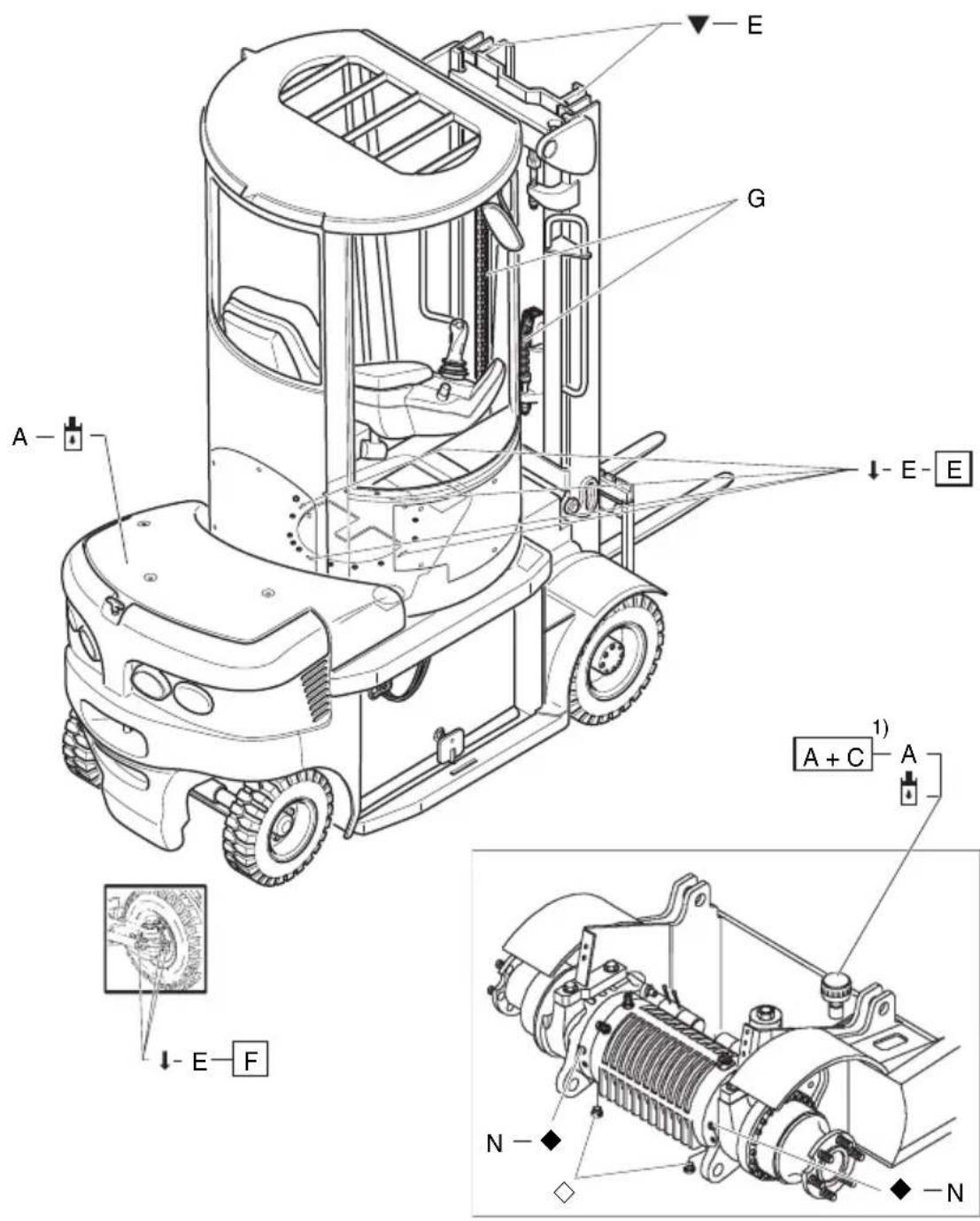
A E G E-E A + C 1) A E-F N- -N▼ Contact surfaces
◆ Transmission oil filler neck
↓Grease nipples ◇Transmission oil drain plug

Hydraulic oil filler neck ●Steering filler neck
Hydraulic oil drain plug
5.1 Consumables
Handling consumables: Consumables must always be handled correctly. Follow the manufacturer's instructions.

Improper handling is hazardous to health, life and the environment. Consumables must only be stored in appropriate containers. They may be flammable and must therefore not come into contact with hot components or naked flames.
Only use clean containers when filling up with consumables. Do not mix consumables of different grades. The only exception to this is when mixing is expressly stipulated in the Operating Instructions.
Avoid spillage. Spilled liquids must be removed immediately with suitable bonding agents and the bonding agent / consumable mixture must be disposed of in accordance with regulations.
| Code | Order no. | Quantity Description | on Used for | |
| A | 50426072 | Renolin 22HV 6834.5 I | Renolin 32^1) HLPD | Hydraulic System, Steering |
| 50429647 | ^2) HLPD | |||
| 50124051 | ^3) | |||
| 51082888 | Plantosyn 46 HVI(BIO hydraulic oil) | |||
| E | 50055726 | Lubrication grease KP 2 K ^3) | Front and rear wheel bearings, live ring | |
| G | 29201280 | Chain spray | Chains | |
| N | 50137755 | 2x approx. 3 litres | Shell Donax TC 50 Universal | Transmission |
| 50426072 | 0.5 I | Renolin 32^1) | Steering | |
| 50100504 | 0.5 I | 10-32^2) | ||
| 50124051 | 0.5 I | HV 68^3) |

The trucks are filled at the factory with H-LPD 22 hydraulic oil or Plantosyn 46 HVI BIO hydraulic oil. You cannot change from “Plantosyn 46 HVI” BIO hydraulic oil to H-LPD 22. The same applies to changing from H-LPD 22 hydraulic oil to Plantosyn 46 HVI BIO hydraulic oil. Furthermore you cannot mix H-LPD 22 hydraulic oil with Plantosyn 46 HVI BIO hydraulic oil.
Grease guidelines
| Code | Saponification | Dew point °C | Worked penetration at 25°C | NLG1 class | Application-temperature °C |
| E | Lithium | 185 | 265-295 | 2 | -35/+120 |
1) applicable for temperatures -5/+30 °C
2) applicable for temperatures -20/-5 °C
3) applicable for temperatures +30/+50 °C
6.1 Prepare the truck for maintenance and repairs
All necessary safety measures must be taken to avoid accidents when carrying out maintenance and repairs. The following preparations must be made:
- Expose the battery (see Chapter D).
6.2 Checking the wheel attachments.
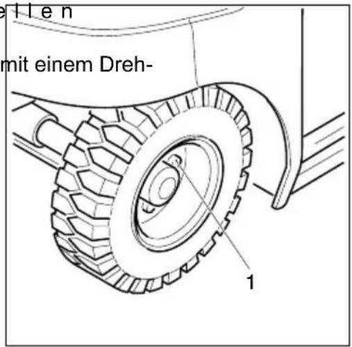
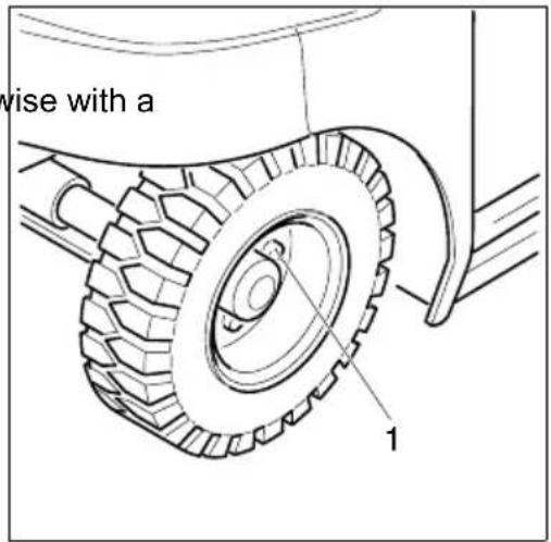
- Park the truck securely (see Chapter E). - Tighten the wheel nuts (1) crosswise with a torque wrench.
Torque
Wheels/drive axle 10 hole wheel rim
$$ M _ {A} = 2 2 0 N m $$
Wheels / steering axle
$$ \mathrm{M} _ {\mathrm{A}} = 1 7 0 \mathrm{Nm} $$
text_image
wise with a 16.3 Tyre pressure
Wheels/Drive axle 10 bar
Wheels/steering axle 7 - 8 bar
6.4 Checking the hydraulic oil level

The load handler must be fully lowered.
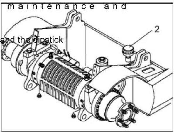
- Prepare the truck for repairs (see Section 6.1). - Unscrew the air filter (2).
text_image
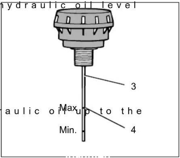
maintenance and and the dipstick 2- Visually inspect the hydraulic oil level on the dipstick (3).

If the reservoir is sufficiently full, the hydraulic oil level will be at the top mark (4).
- If necessary add hyd level indicated (10 mm on the dipstick (3) corresponds to approx. 0.85 litres of hydraulic oil.
text_image
hydraulic oil level 3 Max up to the Min. 4 aulic oil
Do not fill the hydraulic reservoir above the top mark as this can result in malfunctions and system damage.
Used consumables must be disposed of in accordance with the relevant environmental protection regulations.

Trucks with bio hydraulic oil have a warning notice on the hydraulic reservoir: "Fill only with hydraulic oil". Use only bio hydraulic oil, see "Lubricants" section.
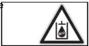
text_image
BIO6.5 Check transmission oil level

Transmission oil must never enter the ground; therefore, place a collection tray underneath the transmission.
- Park the truck secure E).
- Unscrew the oil dipst
- Check transmission o necessary

The oil level should reach the bottom mark of the oil check hole (5a).

Do not fill as far as the oil check hole (6).

Used consumables must be disposed of in accordance with the relevant environmental protection regulations.
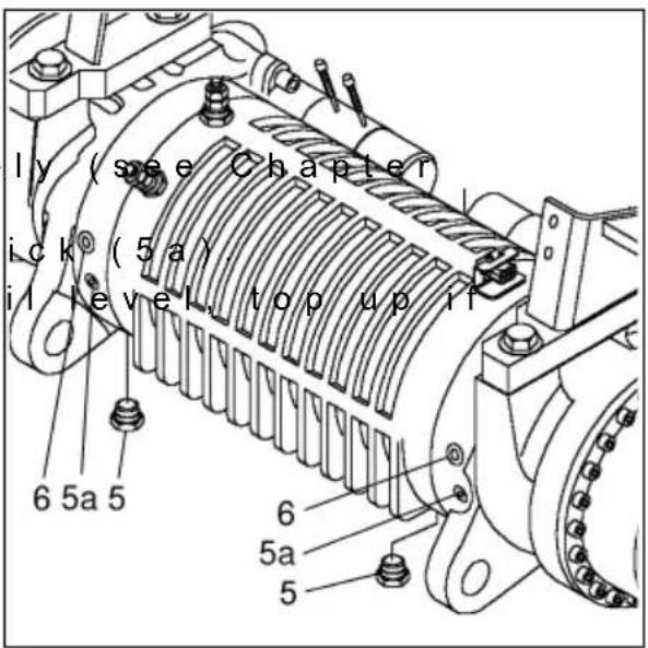
text_image
ly (see Chapter ick (5a) i level, top up if 6 5a 5 6 5a 56.6 Draining the oil
-Drain oil at operating temperature.
- Prepare an oil collection tray underneath.
- Unscrew the oil drain plug (5) and drain the transmission oil.
6.7 Adding oil
- Screw in the oil drain plug, first replacing the seal.
- Unscrew the oil check plug.
- With the oil filler plug (6) unscrewed, add new transmission oil up to the bottom mark of the oil check hole (5a).
- Close the oil filler plug (6) and the oil check plug (5a).
6.8 Replacing the hydraulic oil filter
The hydraulic oil filter is located to the left of the tilt cylinder and can be accessed after removing the front panel.
- Unscrew the hydraulic cap (7).
- Replace the filter ins O ring is also damaged it will also need to be replaced. Apply a thin layer of oil to the O ring on assembly.
-Screw the sealing cap back on.
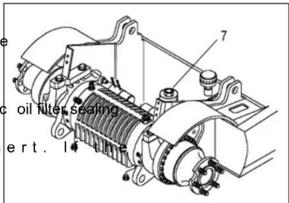
text_image
oil filter sealing ert. 14 the6.9 Seat Belt Maintenance
The driver must check the operation and condition of the seat belt every day before using the industrial truck. Faulty operation can only be detected in good time through regular inspection.
- With draw the belt completely and check the belt for possible fr
- Check the belt lock and make sure that the belt enters the retractor correctly.
- Check the cover for damage
Testing the automatic blocking system:
- Park the truck in a horizontal position.
- Forcibly extract the belt.

The interlock must prevent the belt from coming out.
Do not operate the truck with a faulty seat belt. Replace it immediately.
6.10 Checking electrical fuses
- Prepare the truck for maintenance and repairs (see Section 6.1).
- Open the rear panel or unscrew the electronic cover.
- Unscrew the cover.
- Check condition and rating of the fuses in accordance with

To avoid damaging the electrical system, only use fuses with the correct ratings.
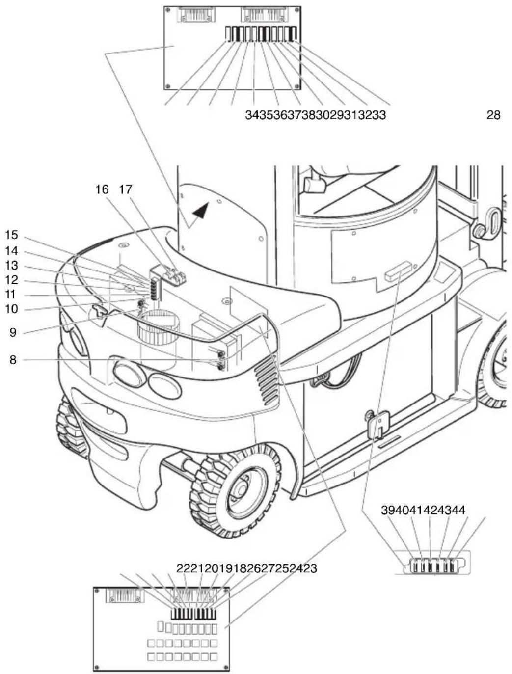
text_image
34353637383029313233 28 16 17 15 14 13 12 11 10 9 8 394041424344 22212019182627252423| Item | Description Current | circuit Rating / type | |
| 8 | 1 | F 1 D r | i v |
| 9 | 2 | F 1 P u | m p |
| 10 1 | F9 Electronic system control fuse 80 volts 5 amps | ||
| 11 Void | |||
| 12 F | 1.2 Control fuse 80 volts 10 | amps | |
| 13 4 | F1 Horn control fuse 5 A | ||
| 14 F | 3.2 Fuse | 24 volts 5 amps | |
| 15 F | 3.1 Control fuse | 24 volts 5 amps | |
| 16 3 | F1 Steering booster motor | 30 A | |
| 17 | F1 | Overall control circuit fuse | 30 A |
| 18 | 5F4.2 | Front tail light control fuse | 5A |
| 19 | 4F5.2 | RH indicator control fuse | 5A |
| 20 | 4F5.1 | LH indicator control fuse | 5A |
| 21 5 | F1 Searchlight control fuse | 7.5A | |
| 22 4 | F6 Brake light control fuse | 5A | |
| 23 | 5F5.3 | RH lights control fuse | 5A |
| 24 | 5F5.1 | LH lights control fuse | 5A |
| 25 | 5F4.1 | Tail lights control fuse | 5A |
| 26 5 | F4 Tail lights control fuse | 5A | |
| 27 5 | F3 Reversing light control fuse | 7,5A | |
| 28 9 | F15 Roof window control fuse | 5A | |
| 29 Void | |||
| 30 9 | F5 Window heating control fuse | 7,5A | |
| 31 | 9F1.1 | Windscreen wiper control fuse | 5A |
| 32 9 | F1 Windscreen wiper control fuse | 5A | |
| 33 Void | |||
| 34 Void | |||
| 35 | 5F1.2 | Search lights aux. 2 control fuse | 5A |
| 36 | 5F1.1 | Search lights aux. 1 control fuse | 5A |
| 37 4 | F4 Beacon control fuse | 5A | |
| 38 | 3F13 | Cabin traverse motor | 80 volt / 15 amp |
| 39 7 | F3 DC/DC converter | 80 volt / 10 amp | |
| 40 F | 13 Solenoid / magnetic brake | 24 volt / 5 amp | |
| 41 4 | F8 Display unit | 24 volt / 5 amp | |
| 42 9 | F2 Seat heating 24 volt / 10 amp | ||
6.11 Returning the truck to service after cleaning or repairs
The truck may only be restored to service after cleaning or repair work, once the following operations have been performed.
- Test horn.
- Test EMERGENCY DISCONNECT switch.
- Test brakes.
– Lubricate the truck in accordance with the maintenance schedule.
7 D e c o m m i s s i o n i n
If the truck is to be decommissioned for more than two months, e.g. for operational reasons, it must be parked in a frost-free and dry location and all necessary measures must be taken before, during and after decommissioning as described.

On decommissioning the truck must be jacked up so that all the wheels are clear of the ground. This is the only way of ensuring that the wheels and wheel bearings are not damaged.
If the truck is to be out of service for more than 6 months, further measures must be taken in consultation with the manufacturer.
7.1 Prior to decommissioning:
-Thoroughly clean the truck.
- Check the brakes.
- Check the hydraulic oil level and replenish as necessary (see Chapter F
- Apply a thin layer of oil or grease to any non-painted mechanical comp
-Lubricate the truck in accordance with the maintenance sc
- Charge the battery (see Chapter D).
- Disconnect the battery, clean it and grease the terminals.

In addition, follow the battery manufacturer's instructions.
- S pay all exposed electrical contacts with a suitable contact spr
7.2 During decommissioning:
Every 2 months: Charge the battery (see Chapter D).

Battery powered trucks
The battery must be charged at regular intervals to avoid depletion of the battery through self-discharge. The sulfatisation would destroy the battery.
7.3 Restoring the truck to operation after decommissioning
-Thoroughly clean the truck.
-Lubricate the truck in accordance with the maintenance sc
- Clean the battery, grease the terminals and connect the battery.
- Charge the battery (see Chapter D).
- Check transmission oil for condensed water and replace if no
- Check hydraulic oil for condensed water and replace if necessary
- Check belt tension on traverse drive.
- Start up the truck (see Chapter E).

Battery powered trucks:
If there are switching problems in the electrical system, spray the exposed contacts with contact spray and remove any oxide layers on the contacts of the operating controls by applying them repeatedly.

Perform several brake tests immediately after re-commissioning the truck.
8 S a f e t y c h e c k s incidents
→ Carry out a safety check in accordance with national regulations. Junheinrich recommends checks in accordance with FEM Guideline 4.004. Jungheinrich has a special safety department with trained personnel to carry out such checks.
The truck must be inspected at least annually (refer to national regulations) or after any unusual event by a qualified inspector. The inspector shall assess the condition of the truck from purely a safety viewpoint, without regard to operational or economic circumstances. The inspector shall be sufficiently instructed and experienced to be able to assess the condition of the truck and the effectiveness of the safety mechanisms based on the technical regulations and principles governing the inspection of forklift trucks.
A thorough test of the truck must be undertaken with regard to its technical condition from a safety aspect. The truck must also be examined for damage caused possible improper use. A test report shall be provided. The test results must be kept for at least the next 2 inspections.
The owner is responsible for ensuring that faults are immediately rectified.
A test plate is attached to the truck as proof that it has passed the safety inspection. This plate indicates the due date for the next inspection.
9 F i n a l d e - c o m m i
Final, proper decommissioning or disposal of the truck must be performed in accordance with the regulations of the country of application. In particular, regulations governing the disposal of batteries, fuels and electronic and electrical systems must be observed.
Instructions for use
Jungheinrich traction battery
Table of contents
1 J u n g h e i n r i c h t r
with positive tubular plates type EPzS and EPzB....2-6
Type plate Jungheinrich traction battery....7
Instruction for use
Aquamatic/BFS III water refilling system....8-12
2 J u n g h e i n r i c h t r
Maintenance free traction batteries with positive tubular plates type EPzV
and EPzV-BS 13-17
Type plate Jungheinrich traction battery....17
1 J u n g h e i n r i c h t
with positive tubular plates type EPzS and EPzB
Rating Data
- Nominal capacity C5: See type plate
- Nominal voltage: 2,0 V x No of cells
- Discharge current:: C5/5h
- Nominal S.G. of electrolyte*
Type EPzS: 1,29 kg/l
Type EPzB: 1,29 kg/l -
Rated temperature: 30^ C
-
Nominal electrolyte level: up to electrolyte level mark „max.“
* Will be reached within the first 10 cycles.


- Pay attention to the operation instruction and fix them close to the battery!
•Work on batteries to be carried out by skilled personnel only!

- Use protective glasses and clothes when working on batteries!
- Pay attention to the accident prevention rules as well as DIN EN 50272-3, DIN 50110-1!

- No smoking!
- Do not expose batteries to naked flames, glowing embers or sparks, as it may cause the battery to explode!
- Acid splashes in the eyes or on the skin must be washed with water. In case of accident consult a doctor immediately!
- Clothing contaminated by acid should be washed in water.
- Risk of explosion and fire, avoid short circuits!
•Electrolyte is highly corrosive!

•Batteries and cells are heavy!
- Ensure secure installation! Use only suitable handling equipment e.g. lifting gear in accordance with VDI 3616.

•Dangerous electrical voltage!
- Caution! Metal parts of the battery are always live. Do not place tools or other metal objects on the battery!
Ignoring the operation instructions, repair with non-original parts or using additives for the electrolyte will render the warranty void.
For batteries in classes ☒ I and ☒ II the instructions for maintaining the appropriate protection class during operation must be complied with (see relevant certificate).
1. Commissioning filled and charged batteries. For commissioning of unfilled batteries see separate instructions!
The battery should be inspected to ensure it is in perfect physical condition.
The charger cables must be connected to ensure a good contact, taking care that the polarity is correct. Otherwise battery, vehicle or charger could be damaged.
The specified torque loading for the polscrews of the charger cables and connectors are:
| steel | |
| M 10 23 | ± 1 Nm |
The level of the electrolyte must be checked. If it is below the antisurge baffle or the top of the separator it must first be topped up to this height with purified water.
The battery is then charged as in item 2.2.
The electrolyte should be topped up to the specified level with purified water.
2. Operation
DIN EN 50272-3 «Traction batteries for industrial trucks» is the standard which applies to the operation traction batteries in industrial trucks.
2.1 Discharging
Be sure that all breather holes are not sealed or covered.
Electrical connections (e.g. plugs) must only be made or broken in the open circuit condition.
To achieve the optimum life for the battery, operating discharges of more than 80% of the rated capacity should be avoided (deep discharge).
This corresponds to an electrolyte specific gravity of 1.13 kg/l at the end of the discharge. Discharged batteries must be recharged immediately and must not be left discharged. This also applies to partially discharged batteries.
2.2 Charging
Only direct current must be used for charging. All charging procedures in accordance with DIN 41773 and DIN 41774 are permitted. Only connect the battery assigned to a charger, suitable for the size of battery, in order to avoid overloading of the electric cables and contacts, unacceptable gassing and the escape of electrolyte from the cells.
In the gassing stage the current limits given in DIN EN 50272-3 must not be exceeded. If the charger was not purchased together with the battery it is best to have its suitability checked by the manufacturers service department. When charging, proper provision must be made for venting of the charging gases.
Battery container lids and the covers of battery compartments must be opened or removed. The vent plugs should stay on the cells and remain closed.
With the charger switched off connect up the battery, ensuring that the polarity is correct. (positive to positive, negative to negative). Now switch on the charger. When charging the temperature of the electrolyte rises by about 10^ C, so charging should only begin if the electrolyte temperature is below 45^ C. The electrolyte temperature of batteries should be at least +10^ C before charging otherwise a full charge will not be achieved.
A charge is finished when the specific gravity of the electrolyte and the battery voltage have remained constant for two hours. Special instructions for the operation of batteries in hazardous areas. This concerns batteries which are used in accordance with EN 50014, DIN VDE 0170/0171 Ex (in areas with a firedamp hazard) or Ex II (in potentially explosive areas). During charging and subsequent gassing the container lids must be removed or opened so that the explosive mixture of gases loses its flammability due to adequate ventilation. The containers for batteries with plate protection packs must not be closed until at least half an hour after charging has past.
2.3 Equalising charge
Equalising charges are used to safeguard the life of the battery and to maintain its capacity. They are necessary after deep discharges, repeated incomplete recharges and charges to an IU characteristic curve. Equalising charges are carried out following normal charging. The charging current must not exceed 5 A/100 Ah of rated capacity (end of charge - see point 2.2).
Watch the temperature!
2.4 Temperature
An electrolyte temperature of 30^ C is specified as the rated temperature. Higher temperatures shorten the life of the battery, lower temperatures reduce the capacity available. 55^ C is the upper temperature limit and is not acceptable as an operating temperature.
2.5 Electrolyte
The rated specific gravity (S. G.) of the electrolyte is related to a temperature of 30^ C and the nominal electrolyte level in the cell in fully charged condition. Higher temperatures reduce the specified gravity of the electrolyte, lower temperatures increase it. The temperature correction factor is -0.0007 kg/l per ^ C, e.g. an electrolyte specific gravity of 1.28 kg/l at 45^ C corresponds to an S.G. of 1.29 kg/l at 30^ C.
The electrolyte must conform to the purity regulations in DIN 43530 part 2.
3. Maintenance
3.1 Daily
Charge the battery after every discharge. Towards the end of charge the electrolyte level should be checked and if necessary topped up to the specified level with purified water. The electrolyte level must not fall below the anti-surge baffle or the top of the separator or the electrolyte „min“ level mark.
3.2 Weekly
Visual inspection after recharging for signs of dirt and mechanical damage. If the battery is charged regularly with a IU characteristic curve an equalising charge must be carried out (see point 2.3).
3.3 Monthly
At the end of the charge the voltages of all cells or bloc batteries should be measured with the charger switched on, and recorded. After charging has ended the specific gravity and the temperature of the electrolyte in all cells should be measured and recorded.
If significant changes from earlier measurements or differences between the cells or bloc batteries are found further testing and maintenance by the service department should be requested.
3.4 Annually
In accordance with DIN VDE 0117 at least once per year, the insulation resistance of the truck and the battery must be checked by an electrical specialist.
The tests on the insulation resistance of the battery must be conducted in accordance with DIN EN 60254-1.
The insulation resistance of the battery thus determined must not be below a value of 50 per Volt of nominal voltage, in compliance with DIN EN 50272-3.
For batteries up to 20 V nominal voltage the minimum value is 1000 Ω.
4. Care of the battery
The battery should always be kept clean and dry to prevent tracking currents. Cleaning must be done in accordance with the ZVEI code of practice «The Cleaning of Vehicle Traction batteries».
Any liquid in the battery tray must be extracted and disposed of in the prescribed manner. Damage to the insulation of the tray should be repaired after cleaning, to ensure that the insulation value complies DIN EN 50272-3 and to prevent tray corrosion. If it is necessary to remove cells it is best to call in our service department for this.
5. Storage
If batteries are taken out of service for a lengthy period they should be stored in the fully charged condition in a dry, frost-free room. To ensure the battery is always ready for use a choice of charging methods can be made:
- a monthly equalising charge as in point 2.3
- float charging at a charging voltage of 2.23 V x the number of cells. The storage time should be taken into account when considering the life of the battery.
6. Malfunctions
If malfunctions are found on the battery or the charger our service department should be called in without delay. The measurements taken in point 3.3 will facilitate fault finding and their elimination.
A service contract with us will make it easier to detect and correct faults in good time.
chemical
Chemical symbols for a recycling and discharge mechanism, including a trigonal cycle and a Pb (potassium) symbolBack to the manufacturer!
Batteries with this sign must be recycled.
Batteries which are not returned for the recycling process must be disposed of as hazardous waste!
We reserve the right make technical modification.
- Type plate, Jungheinrich traction battery
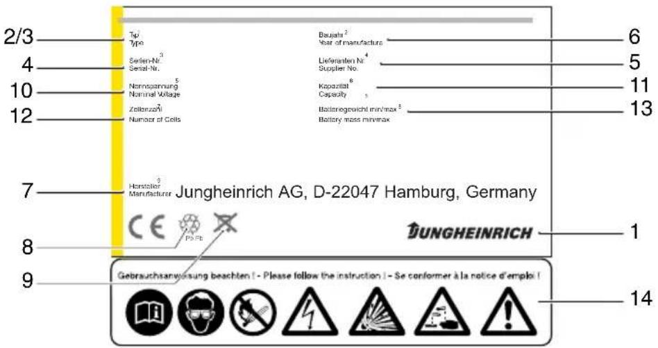
* CE mark is only for batteries with a nominal voltage greater than 75 volt.
Aquamatic/BFS III water refilling system for Jungheinrich traction battery with EPzS and EPzB cells with tubular positive plates
Aquamatic plug arrangement for the Operating Instructions
| Cell series* Aquamatic plug type (length) | |||
| EPzS | EPzB | Frötek (yellow) | BFS (black) |
| 2/120 – 10/ 600 | 2/ 42 – 12/ 252 | 50,5 mm | 51,0 mm |
| 2/160 – 10/ 800 2/ 64 – 12/ 384 50,5 mm 51,0 mm | |||
| – 2/ 84 – 12/ 504 50,5 mm 51,0 mm | |||
| – | 2 / | 1 1 | 0 |
| – | 2/130 – 12/ 780 | 50,5 mm | 51,0 mm |
| – | 2 / | 1 5 | 0 |
| – | 2/172 – 12/1032 | 50,5 mm | 51,0 mm |
| – | 2/200 – 12/1200 | 56,0 mm | 56,0 mm |
| – | 2/216 – 12/1296 | 56,0 mm | 56,0 mm |
| 2/180 – 10/900 – 61,0 mm 61,0 mm | |||
| 2/210 – 10/1050 | – | 61,0 mm | 61,0 mm |
| 2/230 – 10/1150 | – | 61,0 mm 61,0 mm | |
| 2/250 – 10/1250 | – | 61,0 mm | 61,0 mm |
| 2/280 – 10/1400 | – | 72,0 mm 66,0 mm | |
| 2/310 – 10/1550 | – | 72,0 mm | 66,0 mm |
* The cell series comprise cells with two to ten (twelve) positive plates, e.g. column EPzS. 2/120 - 10/600.
These are cells with the positive plate 60Ah. The type designation of a cell is e.g. 2 EPzS 120.
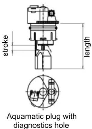
text_image
stroke length Aquamatic plug with diagnostics hole
text_image
stroke length Aquamatic plug BFS III with diagnostics holeNon-adherence to the operating instructions, repairs carried out with non-original spare parts, unauthorised interference, and the use of additives for the electrolytes (alleged improvement agents) will invalidate any claim for warranty.
When using batteries which comply with ExI and ExII, it is important to follow the instructions on maintaining the respective protection class during operation (see associated certification).
Diagrammatic view
Equipment for the water refilling system
- Water tank
- Level switch
- Discharge point with ball valve
- Discharge point with sole-noid valve
- Charger
- Sealing coupler
- Closing nipple
- Ion exchange cartridge with conductance meter and solenoid valve
- Connection for untreated water
- Charging lead
text_image
at least 3 m BUNGHEINRICH1. Design
The Aquamatic/BFS battery water refilling systems are used for automatically adjusting the nominal electrolyte level. Venting holes are provided for letting off the gases which arise during charging. In addition to the optical level indicator, the plug systems also have a diagnostics hole for measuring the temperature and the electrolyte density. All battery cells of the design series EPzS; EPzB can be equipped with the Aquamatic/BFS filling systems. The water can be refilled by means of a central sealing coupler through the hose connections in the individual Aquamatic/BFS plugs.
2. Application
The Aquamatic/BFS battery water refilling system is used in traction batteries for forklift trucks. The water refilling system is provided with a central water connection for the water supply. Soft PVC hose is used for this connection and for the hose connections for the individual plugs. The hose ends are put onto the hose connection sleeves located on the T or < pieces.
3. Function
The quantity of water required in the refilling process is controlled by the valve located in the plug in combination with the float and the float rods. In the Aquamatic System the existing water pressure at the valve turns off the water supply and ensures that the valve closes securely. When the maximum filling level is reached in the BFS system, the float and the float rods through a lever system close the valve with five times the buoyant force and consequently interrupt the water supply reliably.
4. Filling (manual/automatic)
The batteries should be filled with battery water as soon as possible before the battery charging comes to an end; this ensures that the refilled water quantity is mixed with the electrolyte. In normal operation it is usually sufficient to fill once a week.
5. Connection pressure
The water refilling unit is to be operated in such a way that the water pressure in the water pipe is between 0.3 bars and 1.8 bars. The Aquamatic System has an operating pressure range of between 0.2 bars and 0.6 bars. The BFS system has an operating pressure range of 0.3 bars to 1.8 bars. Deviations from the pressure ranges impair the system's functional reliability. This wide pressure range permits three types of filling.
5.1 Falling water
The height of the tank is chosen to suit whichever water refilling system is used. For the Aquamatic System the installation height is 2 m to 6 m and for the BFS system the installation height is 3 m to 18 m over the battery surface.
5.2 Pressurised water
The pressure-reducing valve in the Aquamatic System is set from 0.2 bars to 0.6 bars and from 0.3 bars to 1.8 bars in the BFS system.
5.3 Water Refill Trolley (serviceMobil)
The submergible pump located in the ServiceMobil's tank generates the necessary filling pressure. No difference in height is permitted between the standing level of the ServiceMobil and the standing level of the battery.
6. Filling duration
The length of time needed to fill the batteries depends on the conditions under which the battery is used, the ambient temperatures and the type of filling and/or the filling pressure. The filling time is approx. 0.5 to 4 minutes. Where filling is manual, the water feed pipe must be separated from the battery after filling.
7. Water quality
Only refilling water which conforms in quality to DIN 43530 part 4 may be used to fill the batteries. The refilling unit (tank, pipelines, valves etc.) may not contain any kind of dirt which could impair the functional reliability of the Aquamatic/BFS plug. For safety reasons it is recommendable to insert a filter element (optional) with a max. passage opening of 100 to 300 m into the battery's main supply pipe.
8. Battery hose connections
Hose connections for the individual plugs are laid along the existing electric circuit. No changes may be made.
9. Operating temperature
The temperature limit for battery operation is set at 55^ C. Exceeding this temperature damages the batteries. The battery filling systems may be operated within a temperature range of >0^ C to a maximum of 55^ C.
CAUTION:
Batteries with automatic water refilling systems may only be operated in rooms with temperatures >0^ C (as there is otherwise a danger that the systems may freeze).
9.1 Diagnostics hole
To be able to measure the acid density and temperature easily, the water refilling systems must have a diagnostics hole with a 6.5 mm-diameter (Aquamatic plugs) or a 7.5 mm-diameter (BFS plugs).
9.2 Float
Different floats are used depending on the cell design and type.
9.3 Cleaning
The plug systems may only be cleaned with water. No parts of the plugs may come in contact with soap or fabrics which contain solvents.
10. Accessories
10.1 Flow indicator
To monitor the filling process, a flow indicator can be inserted into the water feed pipe on the battery side. During the filling process, the paddlewheel is turned by the flowing water. When the filling process ends, the wheel stops and this indicates the end of the filling process. (ident no.: 50219542).
10.2 Plug lifter
Only the appertaining special-purpose tool may be used to disassemble the plug systems (plug lifter). The greatest of care must be employed when prising out the plug to prevent any damage to the plug systems.
10.2.1 Clamping ring tool
The clamping ring tool is used to push on a clamping ring to increase the contact pressure of the hose connection on the plugs' hose couplings and to loosen it again.
10.3 Filter element
For safety reasons a filter element (ident no.: 50307282) can be fitted into the battery's main supply pipe for supplying battery water. This filter element has a maximum passage cross-section of 100 to 300 m and is designed as a bag filter.
10.4 Sealing coupler
The water is supplied to the water refilling systems (Aquamatic/BFS) through a central supply pipe. This is connected to the water supply system at the battery charging station by means of a sealing coupler system. On the battery side a closing nipple (ident no.: 50219538) is mounted and the customer must place a sealing coupler construction on the water supply side (obtainable under ident. no.: 50219537).
11. Functional data
PS - self-sealing pressure: Aquamatic > 1.2 bars
BFS system none
D - rate of flow in the opened valve when the pressure is 0.1 bars: 350 ml/min
D1 - maximum permissible leakage rate in the closed valve when the pressure is at 0.1 bars: 2 ml/min
T - p e r m i s s i b l e t e m p e r a t u r e
Pa - operating pressure range: 0.2 to 0.6 bars in the Aquamatic system and operating pressure range: 0.3 to 1.8 bars in the BFS system.
Betriebsanleitung
D
52036693
07.08
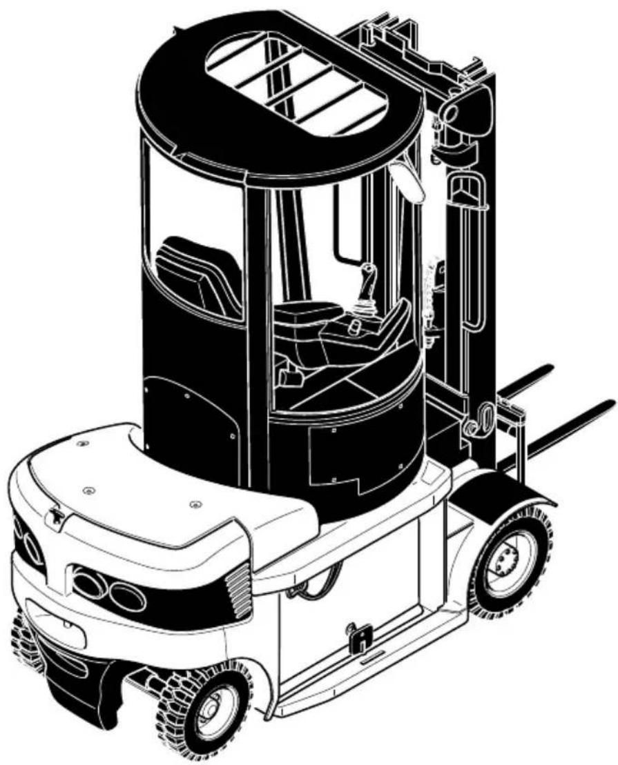
natural_image
Technical line drawing of a forklift carrying a large cylindrical component (no text or symbols)Vorwort
natural_image
Technical line drawing of a forklift carrying a truck, showing internal components and mounting brackets (no text or labels)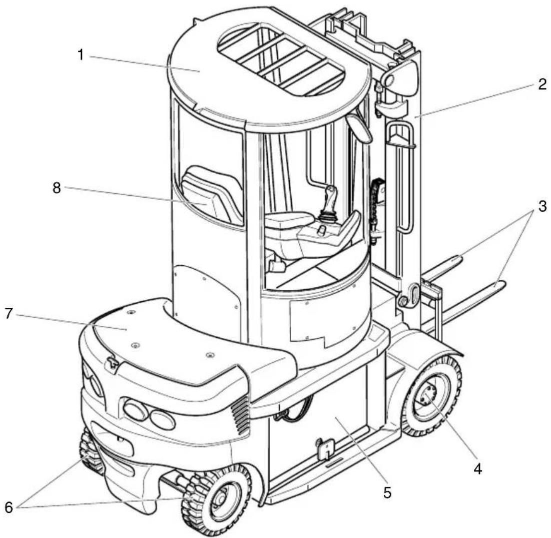
text_image
Technical diagram of a forklift with numbered parts labeled 1 through 81) = + 31 mm DZ-Mast
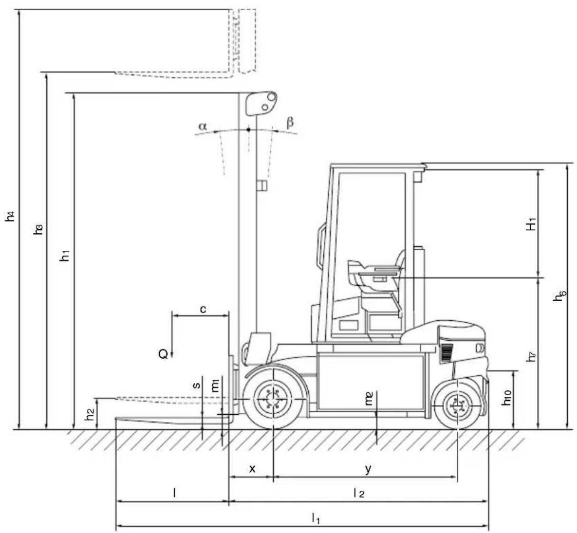
text_image
h4 h3 h1 α β c Q s m1 m2 x y l l2 l1 h10 h6 h7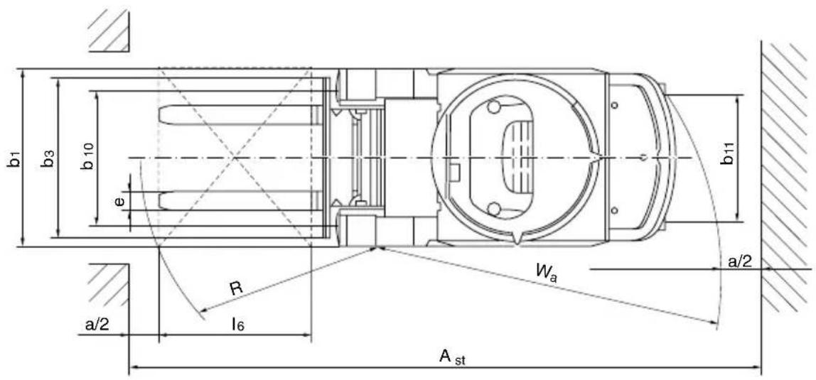
text_image
b1 b3 b 10 φ b11 a/2 R l6 Wₐ Aₛₜ3.1 Leistungsdaten
text_image
Technical diagram of a forklift with numbered parts and safety symbols, including warning signs and safety indicators.other
| Dimension | Value | |---|---| | h3 (mm) | 4250 | | h3 (mm) | 3600 | | h3 (mm) | 2900 | | Q (kg) | 850 | | Q (kg) | 1105 | | Q (kg) | 1250 | | Q (kg) | 850 | | D (mm) | 500 | | D (mm) | 600 | | D (mm) | 700 | Nr. : | Position Label: Nr. : | Subtitle: Q (kg): | Horizontal Labels: d(mm): 4250, 3600, 2900 | | Horizontal Labels: d(mm): 850, 1105, 1250 | | Horizontal Labels: d(mm): 850, 600, 850, 850 | The chart is a schematic representation of a mechanical part with labeled dimensions.text_image
Technical diagram of a forklift with labeled parts 1 and 2, showing internal components and assembly lines.natural_image
Technical line drawing of a forklift with visible gears and levers (no text or symbols)natural_image
Technical line drawing of a mechanical device with wheels and a central housing (no text or symbols)natural_image
Technical line drawing of a forklift with height dimension labeled 'h' and base length 'l' (no text or symbols beyond basic geometry)text_image
Position 4) quench 3 4
text_image
Technical diagram of a mechanical assembly with numbered components and directional arrows indicating motion or assembly.text_image
Technical diagram of a vehicle chassis with labeled parts and an arrow indicating motion directiontext_image
Technical diagram of a mechanical assembly with numbered components and directional arrow indicating motion or force6 B a t t e r i e e n t l a d
text_image
Technical diagram showing a mechanical device with labeled parts and directional arrows indicating motion or assembly.natural_image
Line drawing of a car interior with steering wheel, dashboard, and control panel (no text or symbols)text_image
Prohibition sign with pictogram of a person without a weight, indicating no intervention or absence of weight lossnatural_image
Diagram of a forklift lifting a truck, showing motion direction (no text or symbols)Last transportieren

natural_image
Diagram showing a forklift lifting a table and a load, with no text or symbols present.$$ M _ {A} = 2 2 0 N m $$
Räder / Lenkachse
$$ M _ {A} = 1 7 0 \mathrm{Nm} $$