
MG96MF/CIS - Cooker LOFRA - Free user manual and instructions
Find the device manual for free MG96MF/CIS LOFRA in PDF.


User questions about MG96MF/CIS LOFRA
0 question about this device. Answer the ones you know or ask your own.
Ask a new question about this device
Download the instructions for your Cooker in PDF format for free! Find your manual MG96MF/CIS - LOFRA and take your electronic device back in hand. On this page are published all the documents necessary for the use of your device. MG96MF/CIS by LOFRA.
USER MANUAL MG96MF/CIS LOFRA
natural_image
Abstract white angular shape on a solid green background (no text or symbols)LOFRA®
MADE IN ITALY

Gentile Cliente,
natural_image
Pure architectural line drawing of a building facade with windows and doorways (no text or symbols)natural_image
Symbol of a person falling off a slope with a diagonal line, no text or numbers present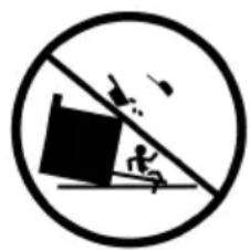
natural_image
Symbolic illustration of a person falling off a slope with a diagonal line and birds flying above (no text or numbers present)text_image
Technical diagram showing a rotary dial with multiple rotary gauges and labeled measurement points, alongside a separate panel labeled 'Made'.Piastra Vetroceramica
Forno MF 70 I
Forno MF 95 I
Bruciatore Dual
text_image
Diagram showing various kitchen control knobs and temperature readings, including alarm clock, timer, and door.text_image
12.30 LOFRA Made in ItalyForno MF 60 I (Superiore Dx)
text_image
12.30 LOFRA Made in Italynatural_image
Person in white shirt handling a large cylindrical object in front of a stainless steel kitchen appliance (no visible text or symbols)Fig. 1
natural_image
Person in white coat operating a stainless steel gas stove with control knobs (no visible text or symbols)Fig. 2
natural_image
Person cooking on a stainless steel stove with red prohibition symbol (no text or symbols on the stove itself)Fig. 3
natural_image
Person in white coat standing near a kitchen counter with red X marks (no visible text or symbols)Fig. 4

text_image
Technical diagram showing mechanical assembly with dimension annotations including 31, 16, and slcFig. 7 Fig. 8
text_image
MIN. 66 cm MIN. 5 cm MIN. 2 cmFig. 6

Fig. 9
text_image
3 CM MIN 12 CM MIN 12 CM3.5 MONTAGGIO PIEDINI
natural_image
Close-up of a black cylindrical object with reflective surface, possibly a pipe or tube (no visible text or symbols)
natural_image
Close-up of a hand holding a black cylindrical object with a circular opening, next to a metallic door (no visible text or symbols)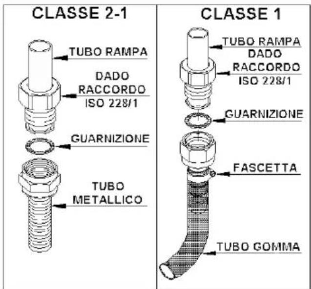
text_image
CLASSE 2-1 TUBO RAMPA DADO RACCORDO ISO 228/1 GUARNIZIONE TUBO METALLICO CLASSE 1 TUBO RAMPA DADO RACCORDO ISO 228/1 GUARNIZIONE FASCETTA TUBO GOMMA
SOLO PER I MODELLI: MR96GV/C, MR96MF/C
(OMOLOGATI PORTA BOMBOLA)
natural_image
Two mechanical diagrams labeled A and B showing different types of tool assemblies with rotating components (no text or symbols present)3.10 TRASFORMAZIONE DEL GAS SUI BRUCIATORI FORNO E GRILL GAS
Fig. 10
text_image
Technical diagram showing mechanical components with labeled parts A, B, and C, likely illustrating a gear or mechanism assembly.Bruciatore forno.
natural_image
Simple line drawing of a vertical pole with a base and a circular symbol labeled B (no text or symbols present)4.3 SMONTAGGIO E MONTAGGIO DELLA PORTA DEL FORNO
natural_image
Technical line drawing of a mechanical assembly with labeled component A (no text or symbols beyond label)natural_image
Close-up of mechanical components with no visible text or symbolsnatural_image
Close-up of a white industrial machine with visible internal components and ventilation slots (no text or symbols)ABC
natural_image
Close-up of a mechanical device with metal components and wiring (no visible text or symbols)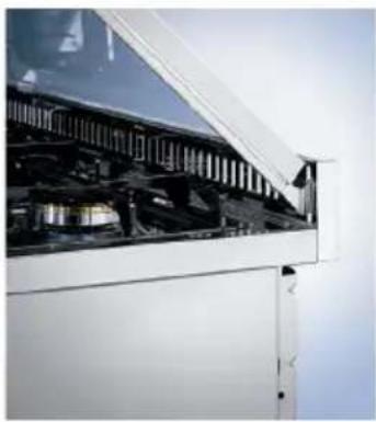
natural_image
Exterior view of a modern office building (no signage)5. USO DELLA CUCINA
AVVERTENZE:
natural_image
Line drawing of an oven with control panel and door (no text or symbols)
FORNO ELETTRICO
Forni statici
natural_image
Technical line drawing of a mechanical assembly with layered components (no text or symbols)
natural_image
Technical line drawing of a mechanical assembly with no visible text or symbols
5.13 GUIDE TELESCOPICHE (SOLO PER I MODELLI PREVISTI)
natural_image
Technical line drawing of a rack frame structure with an arrow indicating direction (no text or symbols)5.14 GRIGLIE CON DISPOSITIVO ANTI-CADUTA
natural_image
Symbol of a trash bin with crossed lines and a horizontal bar below (no text or labels)We thank you and congratulate you on granting us your preference, by purchasing one of our products. We are sure that this new appliance, manufactured with quality materials, will meet your requirements in the best possible way.
The use of this new equipment is easy. However, we invite you to read this booklet carefully, before installing and using the appliance.
This booklet gives the right information on the installation, use and maintenance, as well as useful advice.
THE MANUFACTURER
LOFRA S.R.L.
SUMMARY
- SAFETY INSTRUCTIONS 59 1.1 - Preliminary instruction
60 1.2 - Safety during the use
63 1.3 - Electrical safety
64 1.4 - Children's safety
65 1.5 - Safety during cleaning
65
66 1.7 - Producer responsibility
1.6 - Disposing of the packaging materials
-
FEATURES 67
-
INSTALLATION OF THE
COOKER 73
74 3.1 - Lifting instructions
74 3.2 - Ventilation
75 3.3 - Discharge of fuel gas
75 3.4 - Positioning the cooker
77 3.5 - Leg fitting instructions
78 3.6 - Connection to the gas supply
79 3.7 - Connection to the electricity supply
80 3.8 - Converting gas-supply to the hob burners
80 3.9 - Regulating the minimum output of burners
80 3.10- Converting gas-supply to the oven burner
and gas grill
- MAINTENANCE 81 4.1 - Gas supply rubber pipe
81 4.2 - Electricity supply cable
81
4.3 - Removing and fitting the oven door
82 4.4 - Replacing the light bulb
82 4.5 - Glass cover
5. USING THE COOKER 83
83 5.1 - Using the cooking hob
84 5.2 - Oven performance
86 5.3 - Rotisserie
87 5.4 - Minute timer
87 5.5 - Multiple-function cookers
87 5.6 - Electronic programmer
91 5.7 - List of functions MF and MFR
92 5.8 - Up&Down cooker
94 5.9 - Timer touch control
96 5.10 - Vitroceramic cooking hob
101 5.11 - Telescopic guides
101 5.12 - Tray with anti-fall device
101 5.13 - Gas burner series III fitting instructions
- CLEANING 102
- WARRANTY 102
- BURNER SPECIFICATIONS 105
1. SAFETY INSTRUCTIONS
Please read the entire service manual before installing and using the oven.
For any request for intervention made by the technician, with the guarantee, the document proving the purchase data or the delivery data.
Please keep this booklet together with the equipment for any future consultation.
If this equipment should be sold or transferred to another person, make sure that the new user receives the booklet, so that he can learn how to operate the appliance and read the corresponding notice.
This appliance is class 3 and has been designed for domestic use only.
1.1 PRELIMINARY INSTRUCTION
Before using the cooker, remove the plastic protection
- from the stainless steel, alluminium ad/or painted parts in order to prevent it melting. The utmost care must be taken when removing this protection so as to avoid damaging the protected parts.
Before using the oven for the first time it's recommended to
- turn it on to the maximum temperature and leave it to heat for an hour. During this period there may be some smell and smoke due to the oven's thermal insulation adhesives and oils. It is recommended to leave a window open for the air to circulate.
This appliance is not intended for use by person (including
- children) with reduced physical, sensory or mental capabilities, or lack of experience and knowledge, unless they have been given supervision or instruction concerning use of the appliance by a person responsible for their safety.
Make sure there is an air circulation around the gas appliance.
- A poor ventilation produces oxygen deficiency.
This appliance has been specifically designed for domestic use only.
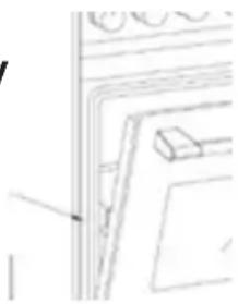
These instruction are only valid for the country indicated in the identification symbols on the appliance (see the image).
natural_image
Pure architectural line drawing of a building facade with windows and doorways (no text or symbols)! Information about this model and its features is displayed on the appliance plate.
! The appliance must not be installed behind a decorative door to prevent overheating.
! Periodically check that there are no gas leaks from the connection pipe between the cooker and the bottle or supply line; replace upon expiry.
! Keep the burners, covers and flame diffusers clean in order to ensure optimum operation.
! Cooking zones must not operate without the pans.
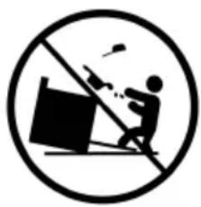
! Caution, possibility of tilting. In order to prevent tipping of the appliance, this stabilising means must be installed.
natural_image
Symbol of a person falling off a slope with a diagonal line, no text or numbers present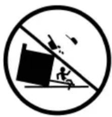
natural_image
Symbolic illustration of a person running on a slope with a block and flying birds, enclosed in a circle (no text or numbers present)! If the range is placed on a base, measures have to be taken to prevent the appliance slipping from the base.
! Danger of fire: do not store items on the cooking surfaces. During use, the appliance becomes hot.
Care should be taken to avoid touching heating elements inside the oven.
! The products of combustion must be discharged to the outside through a suction hood or electric fan (see paragraph "installation").
! Unattended cooking on a hob with fat or oil can be dangerous and may result in fire. NEVER try to extinguish a fire with water, but switch off the appliance and then cover flame e.g. with a lid or a fire blanket.
! Do not cover the bottom of the oven with an aluminum foil and do not place the aluminum pan on the bottom of the oven during its operation.
! Some models are equipped with an aluminum baking tray, ideal for baking pastry (180 - 200 °C), load a maximum of 3 kg.
! Do not use steel wool, abrasive powders and corrosive substances that could scratch. Do not use steam cleaners to clean the appliance.
! If the glass ceramic surface should ever get broken, unplug the appliance and contact an authorized centre.
! The cover is made of hardened glass. Do not close it when the burners or electric plate are on, or still hot, as this could breach the glass and create a hazard.
When the cooker is not in use, ensure that all the knobs are in the off position; furthermore, if it is unused for a period of time, shut off the gas bottle valve and the supply valve, as well as the appliance's mains electricity supply.
! Remove any objects from the top of the cover before opening it.
! Use only hob guards designed by the manufacturer of the appliance in the instructions for use as suitable or hob guards incorporated in the appliance.
The use of inappropriate guards can cause accidents.
! The preparation of food in plastic and aluminum containers is prohibited. Plastic and aluminum objects must not be placed on the hot glass ceramic hob.
In case of intensive or prolonged use of the appliance, it may require additional ventilation, for example opening a window or increasing the mechanical suction power if it exists.
! The appliance is not intended to be operated by means of an external timer or separate remote control system.
Before powering the appliance check that it is properly
- adjusted for the type of gas available.
For any interventions or modifications, contact an authorized
- Technical Assistance Center and request original spare parts.
For any interventions or modifications, contact your
- Authorized Lofra Service Center and request original spare parts.
If the power cord is damaged it must be replaced by the
- supplier, by an after sales service or qualified personnel in order to avoid dangers.
It is necessary to provide an omnipolar network isolator
- in the power supply network, or one that allows complete disconnection from the grid, having contacts suitable for the overvoltage category III.
The switch must be easily accessible after installing the appliance.
In the cookers that do not have a power cord, this manual
indicated the type of cable to use, teaking into account the temperature of the rear surface of the device.
Before replacing the bulb, disconnect the unit from the
● electricity supply and, if recently used, make sure that the oven has cooled down.
Before carrying out any assistance operation, disconnect the
● power supply and close the gas upstream of the appliance.
In the case of replacement of components and / or accessories, use only original Lofra spare parts. Rely on qualified technical personnel only.
If the surface of the grill is cracked, switch off the switch to
the appliance to avoid the possibility of electric shock.
If the pyroceram plate brakes, turn off the power supply and
- call your Authorized Lofra Service Center.
Ensure that the appliance is switched off before replacing the
- lamp to avoid the possibility of electric shock.
1.4 CHILDREN'S SAFETY
This appliance can be used by children aged from 8 years and
● above and persons with reduced physical, sensory or mental capabilities or lack of experience and knowledge if they have been given supervision or instruction concerning use of the appliance in a safe way and understand the hazards involved.
The accessible parts get very hot when the grill is in use.
- Keep children at a safe distance.
Cleaning and user maintenance shall not be made by children
- without supervision.
Children shall not play with the appliance.
When using the oven its surfaces will get hot: always keep
children and people with learning disabilities at a safe distance and avoid letting them operate the oven.
Children less than 8 years of age shall be kept away unless
• continuously supervised.
1.5 SAFETY DURING CLEANING
It's recommended to disconnect the oven before cleaning it.
! Clean the oven using tepid water and a neutral detergent; rinse well using a damp cloth. Wash the oven's accessories separately in a dishwasher or by using tepid water and a neutral detergent; dry them with a soft cloth.
Do not use harsh abrasive cleaners or sharp metal scrapers to clean the oven door glass since they can scratch the surface, which may result in shattering of the glass.
1.6 DISPOSING OF THE PACKAGING MATERIALS
! Do not dispose of the packaging, accessories or anything else inherent to the appliance in the environment.
Use the appropriate bins in accordance to the laws in force.
Technical specifications and Information regarding the
- model can be obtained from the technical data plate on the appliance.
Installation, regulations, alterations and maintenance
- procedures must be done by qualified personnel only in accordance to this manual and laws in force. The company will not be liable for any type of damage derived from improper voltage or other misuse, abnormal service or handling and alterations or modifications in design.
When obtaining service be sure to show the technician, along
- with the warranty, the document stating the date of purchase or the date of delivery.
All installation, adjustments, gas-conversion and maintenance
● operations must be carried out by qualified engineers, in accordance with the enclosed instructions and current installation standards.
The manufacturers accepts no liability for faulty installation, setting, handling and use of the cooker.
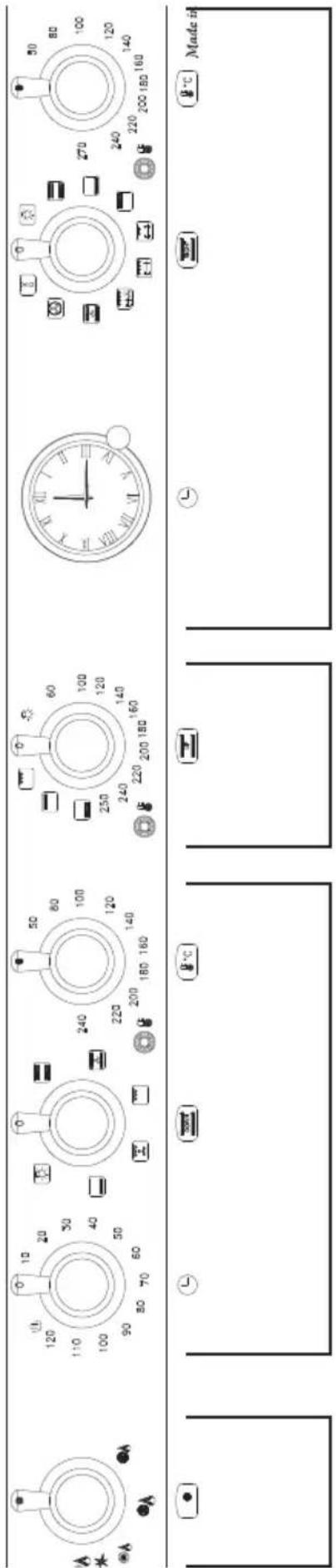
1. FEATURES: RSD156 MFT+MFT-AEOV
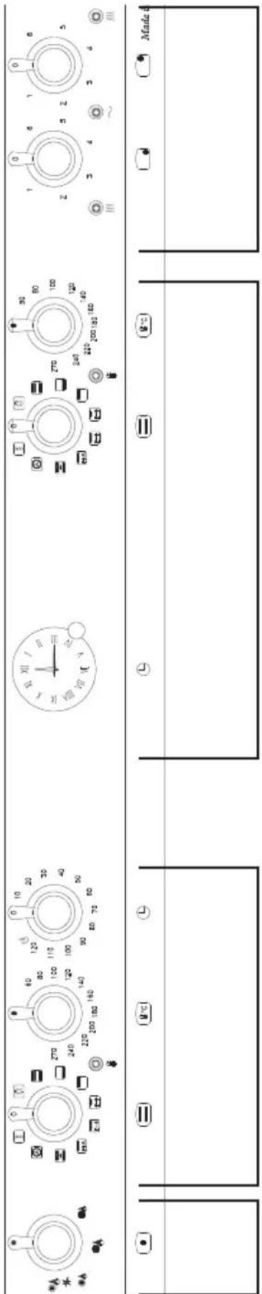
text_image
Diagram showing various rotary dial indicators with labeled ranges and a 'Made' button, likely for industrial control or measurement.Vitroceramic glass plate
MF 70 I oven
MF 95 I oven
Dual burner
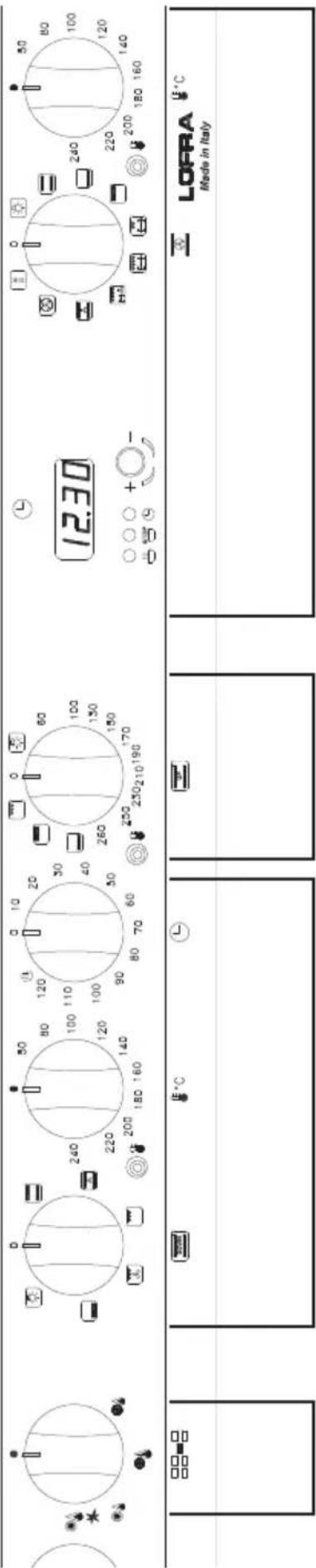
RR126SMFET+MF-2AEO

text_image
Cropped image showing multiple industrial control panel designs with labeled buttons and numeric readings, likely from a machine control system.MF 60 I oven
(Upper Right)
Static electric oven 40l (Upper Left)
SMF 60 I oven
(Lower left)
Dual burner
text_image
Cropped image of a home control panel with analog clocks, temperature readings, and a digital display showing 12.30°C.MF 60 I oven
(Upper Right)
Static electric oven 40l (Upper Left)
SMF 60 I oven
(Lower Left)
Dual burner
PD126MF+E2CiK

text_image
12.30 LOFRA Made in ItalyStatic electric oven 30 l
MF 90 I oven
Dual burner
text_image
Made in ItStatic electric oven 30 l (Right)
Static electric oven 40 l (Upper Right)
MF 60 I oven (Lower Left)
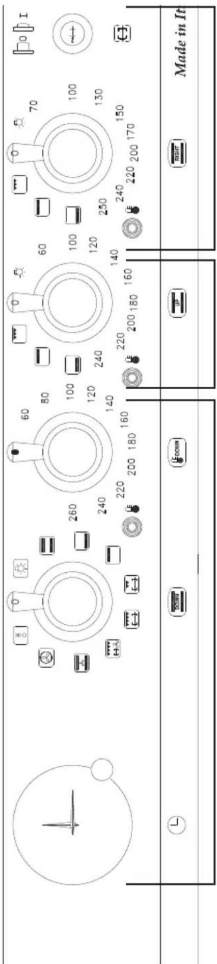
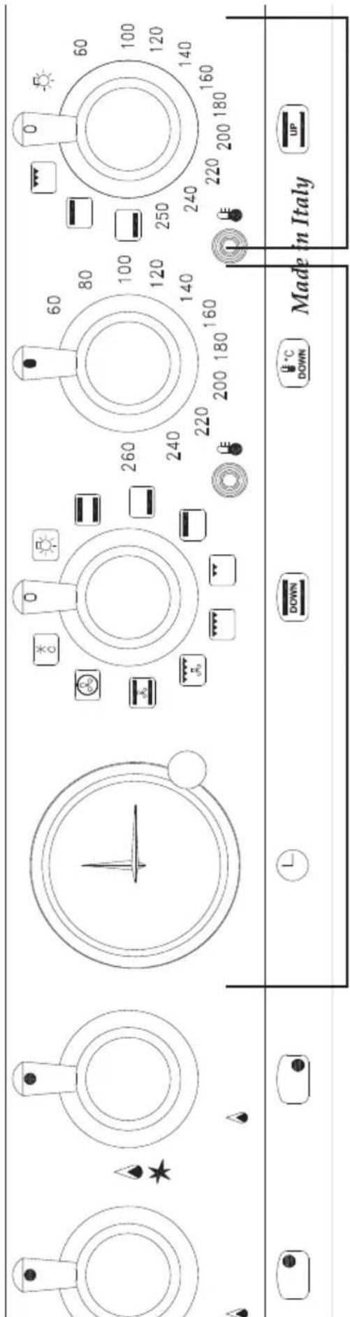
RNMUD76MFTE-Ci
text_image
Made in Italy DOWN DOWN C 260 240 220 200 180 160 60 80 100 120 140 250 240 220 200 180 160 CE CE UP C AStatic electric oven 40 l (Upper)
MF 60 I oven
(Lower)
WARNING:
This appliance shall be installed in accordance with the regulations in force and only in a well ventilated space.
Read the instructions before installing or using the appliance. In the UK the regulations and standards are as follows:
In your own interest and that of safety, it is law that all gas appliances be installed by competent persons. CORGI registered installers undertake to work to safe and satisfactory standards. Failure to install the appliance correctly could invalidate any warranty of liability claims and lead to prosecution.
The cooker must be installed in accordance with all relevant British Standards / Codes of Practice, in particular BS 5440 Part 2 2000 and:
- For Natural Gas – BS6172: 1990 and BS6891: 1988
- For LP Gas – BS5482 Part 1 (when the installation is in a permanent dwelling), Part 2, (when the installation is in a caravan or other non permanent dwelling), or Part 3 (when installing is in a boat).
- The Gas Safety (Installing and Use) regulations 1994 (as amended).
- The relevant Building /IEE regulations.
- The cooker may be installed in a kitchen / kitchen diner but NOT in a room containing a bath or shower.
- If the appliance is for use on LPG it must not be fitted below ground level, i.e. in a basement.
3.1 LIFTING INSTRUCTIONS
For the fixing of the cooker with brakers, see section 1.3.
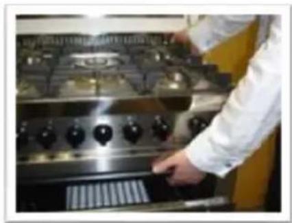
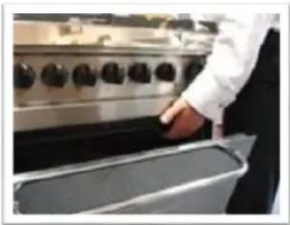
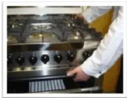
To lift the cooker, open the oven door and lift by the oven cavity and the over hang at te rear of the appliance (fig. 1 and 2).
natural_image
Person in white shirt handling a large cylindrical object in front of a stainless steel kitchen appliance (no visible text or symbols)Fig. 1
natural_image
Person in white coat operating a stainless steel gas stove (no visible text or symbols)Fig. 2
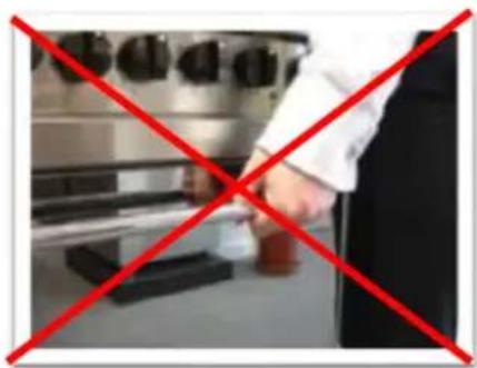
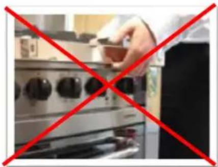
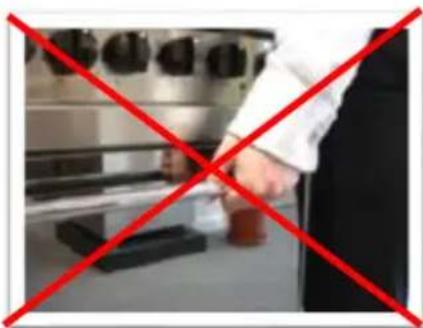
DO NOT lift the cooker by the overhang of the hob top at the front of the appliance or by the door handle (fig. 3 and 4).
natural_image
Person cooking on a stainless steel stove with red prohibition symbol (no text or symbols on the image itself)Fig. 3
natural_image
Person in kitchen setting with red X-shaped mark (no text or symbols visible)Fig. 4
Lifting the appliance by the hob can cause the securing brakets to break and damage the gas pipes to the burners on the hob.
Lifting the appliance by the door handle can chip or break the outer door glass. Any resulting damage is NOT covered by the guarantee.
3.2 VENTILATION
The room containing this cooker should have an air supply in accordance with BS 5440: Part 2: 1989
- All rooms require an openable window, or equivalent and some rooms will require a permanent vent a well.
- For room volumes up to 5 m3 an air vent of 100 cm2 is required.
- For room volumes between 5 m3 and 10 m3 an air vent of 50 cm2 is required.
- If the room is greater than 5 m3 and has a door that opens directly to the outside, then no air vent is required.
- If there are other fuel burning appliances in the same room BS 5440: Part 2:1989 should be consulted to determine the air vent requirements.
- This appliance should not be installed in a bed sitting room of less 20 m3 or in bathroom or shower room.
text_image
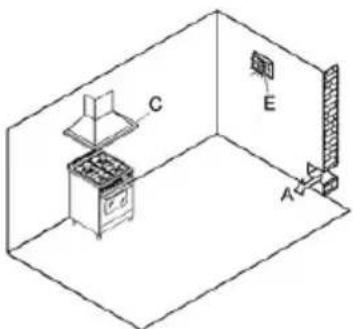
Diagram of a room interior with labeled components A, C, and E, showing a stove, oven, and wall-mounted equipment.Cooking appliances must always discharge the flue gases into special hoods, which must be connected to chimneys, flue pipes or have directly access to the outside.
If it is not possible to connect a hood, an electric fan can be fitted to a window or a wall, which must be turned on when the cooker is on, as long as ventilation standards are strictly adhered to.
3.4 POSITIONING THE COOKER
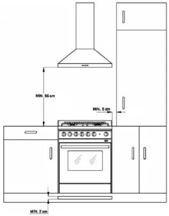
a) Built-in cooker: type Y - class 2 subclass 2/1 Cookers in this class can be fitted between two units, unless the side in contact with the cooker is higher than the hob. In this case, the unit must stand at least 5cm away from the top of the hob. If the cooker has a baseboard fitted, a 2cm vent must be made in the front along the entire width of the cooker.
b) Free standing cooker: type X – class 1; point a) also applies to this class, with the exception that one side of the cooker must be left free so that the flexible rubber gas piping, can be inspected.
After unpacking the cooker, remove the plastic protection from the stainless steel, aluminium and/or painted parts to avoid it melting.
The utmost care must be taken when removing this protection so as not to damage the protected parts. Now the feet can be fitted.
They must be fixed to the ends of the slits on the cooker pedestal.
Their height can be adjusted in order to line the cooker up with other units.
Ensure that the cooker is perfectly stable. Fit the burners, the flame diffusers and the grids into their seats on the hob.
Some models come with rubber pads that prevent the steel hob surface from being scratched.
Fit them to the central pan grid made of chrome-plated rod.
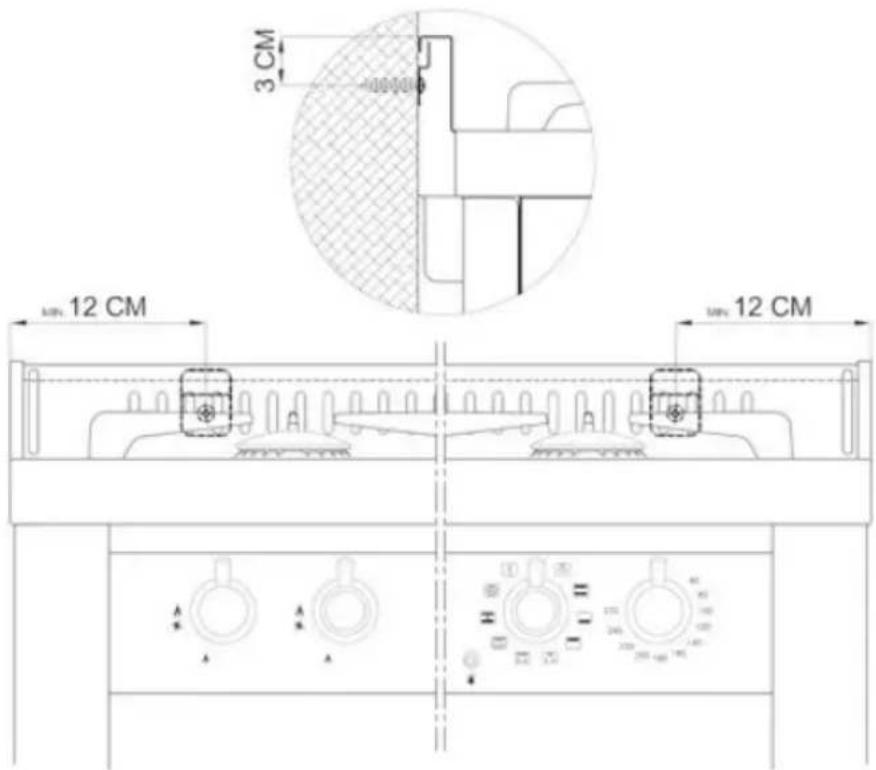
For the installation, anchor the cooker by using the supplied kit referring to the relevant drawing. We provides two brackets, which will serve to anchor the wall-terminal of the cooker. We must fix the brackets to the wall, following
text_image
MIN. 65 cm MIN. 5 cm MIN. 2 cm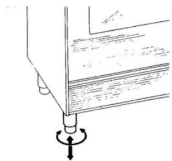
natural_image
Technical diagram showing a mechanical assembly with rotating components (no text or symbols)the instructions of the drawings. We must then slightly lift the cooker to let in the bracket on the crease of the wall-terminal or working top cooker.
N.B.: The cooker with and without splashback must be raised slightly in order to let the bracket on the edge of the hob.
Note: When the burners are alight, there must not be any draughts inside the room in that they may affect the flame or even blow it out.
The fixing hook is not provided as the type will depend on the construction of the wall to which it will be drilled and fitted.
The installer should provide the fixing hook.

text_image
3 CM MIN 12 CM MIN 12 CM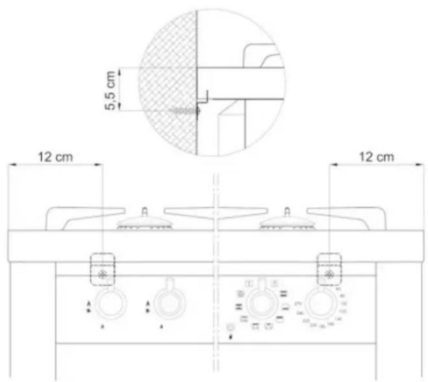
text_image
5,5 cm 12 cm 12 cm3.5 LEG FITTING INSTRUCTIONS
-
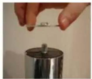
When fitting the washer to the leg bolt make sure the burr on the washer is facing upward away from the leg top.
-
Leg assembly with washer fitted correctly. The lower part of the leg will unscrew to adjust the height and level of the cooker.
-
Leg insert cut out on base of oven. To fit the legs to the appliance lie the cooker flat on its back and fit all four legs.
DO NOT fit legs to the cooker by tilting the appliance, doing so may damage the leg assembly.
-
Insert washer fitted to top of leg into base of cooker and slide the leg along the channel.
-
Screw the leg up tight so the oven base is clamped between the washer and the top of the leg. Once all four legs have been fitted lift cooker onto the legs taking care to distribute the weight evenly onto all four legs at the same time.
DO NOT tip the appliance onto its legs, always lift the appliance onto its legs. (This will require two people)
natural_image
Close-up of a hand holding a small metallic object above a metallic cylindrical container (no visible text or symbols)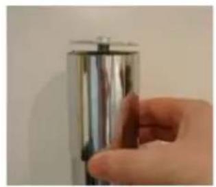
natural_image
Hand holding a metallic cylindrical object against a plain wall (no text or symbols visible)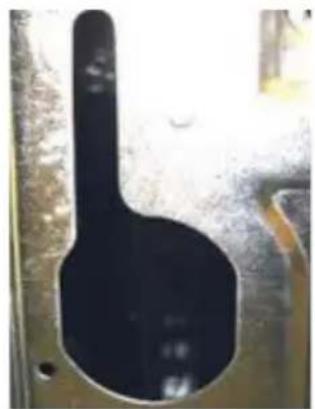
natural_image
Close-up of a black mechanical component with a circular opening, possibly a tool or part (no visible text or symbols)
natural_image
Close-up of a black pipe fitting with white markings, no visible text or symbols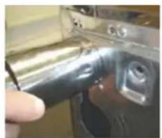
natural_image
Close-up of a hand using a tool to adjust or install a mechanical component (no visible text or symbols)3.6 CONNECTION TO THE GAS SUPPLY: CURRENT INSTALLATION
STANDARDS
The cooker should be connected according BS 6172-1990, using either a rigid or flexible connections.
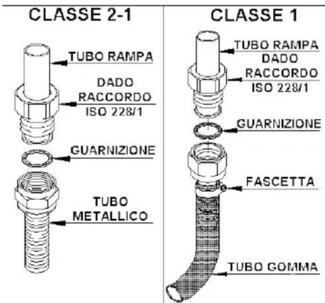
a) Class 2 (Built-in cooker sub-class 2/1): use a continuous flexible stainless steel pipe, as per current installation standards, which can be extended to a maximum of 2000 mm.; the ends of the pipe must be fitted with an ISO 228/1coupling and gasket or an ISO 7/1 threaded coupling with mechanical gasket.
b) Class 1 (Free-standing cooker): Class 2 instructions also apply. In addition, a non-metallic flexible pipe can be used as long as it complies with current standards and the following installation instructions are observed: the pipe must be longer than 400 mm and shorter than 1500 mm; it must not exceed 50C in any point; it is not pulled or twisted; it cannot be choked and the entire edges, sharp corners or other similar hazards.
Before connecting the non-metallic flexible pipe, the pipe holder and gasket supplied with the cooker and/or available form the reseller
must be fitted to the pipe/gas train on the back of the cooker.
For connection to:
- Methane gas: the pipe must have an internal diameter of 13 mm, be fitted to the pipe holder and then blocked with a specific clamp as per current installation standards;
- Liquid gas (bottle): the pipe must have an internal diameter of 8 mm, be fitted to the pipe holder and then blocked with a
text_image
CLASSE 2-1 TUBO RAMPA DADO RACCORDO ISO 228/1 GUARNIZIONE TUBO METALLICO CLASSE 1 TUBO RAMPA DADO RACCORDO ISO 228/1 GUARNIZIONE FASCETTA TUBO GOMMASCHEMA COLLEGAMENTO DEL TUBO FLESSIBILE TRA
BOMBOLA E CUCINA CON PORTAGOMMA
specific clamp as per current installation standards. The bottle must be fitted with a pressure reducer as per current installation standards.
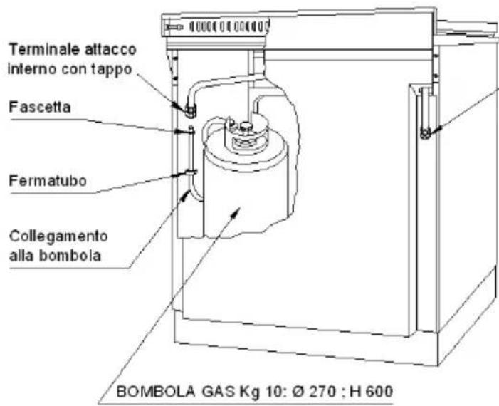
Cookers with bottle cupboard IF INSTALLATION STANDARDS PERMIT.
These cookers are designed prepared for use with bottle of liquid gas (size ∅ 270 mm, height 600 mm). They are fitted with two attachments for the gas connection: one inside the cupboard and one on the back hand side.
The bottle cupboard attachment is sealed with a cap and a gasket, while the other end is open. If the bottle cupboard attachment is used, the cap must be replaced with the pipe holder must be connected with a flexible pipe, which must follow the route shown in the adjacent diagrams and/or on the adhesive plate fitted inside the bottle cupboard door.
After connection, ensure that there are no gas leaks by using a specific instrument or soapy water.
3.7 CONNECTION TO THE ELECTRICITY SUPPLY
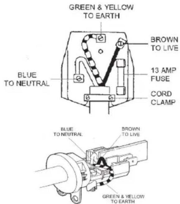
The flexible mains lead is supplied connected to a BS 1363 fused plug fitted with a fuse of 13 amp capacity. If you need to replace the plug for any reason, it should be carried out as outlined below.
WARNING: THIS APPLIANCE MUST BE EARTHED.
text_image
GREEN & YELLOW TO EARTH BROWN TO LIVE 13 AMP FUSE BLUE TO NEUTRAL CORD CLAMP BLUE TO NEUTRAL BROWN TO LIVE GREEN & YELLOW TO EARTHThe wired in the mains lead are coloured in accordance with the following code:
Green & Yellow = Earth - Blue= Neutral - Brown= Live
As the colours of the wires in the mains lead of the appliance may not correspond with the coloured markings identifying the terminals in your plug, proceed as follows:
-
The wire which is coloured Green & Yellow must be connected to the terminal marked E (Earth) or coloured Green.
-
The wire which is coloured Blue must be connected to the terminal marked N (Neutral) or coloured Black.
-
The wire which is coloured Brown must be connected to the terminal marked L (Live) or coloured Red.
The plug and socket must be accessible after installation. Should the mains lead ever need replacing it is recommended that this operation is carried out by a qualified electrician who will replace it with a lead of the same size and temperature rating.
If a fixed instrument has not any cable nor pin, or any other device which assures the worknet disconnection, with a distance of opening of the contacts that allows the complete disconnection in the conditions of overvoltage category III, the instructions have to inform that such disconnection devices have to be provided for by the supply mains in conformity with the installation rules.
Terminal connection diagram with cable pre-installed
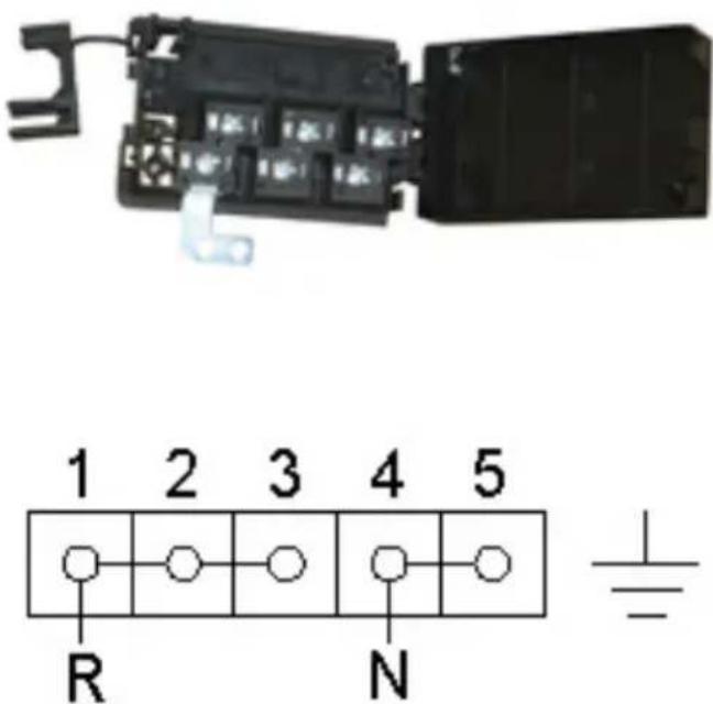
text_image
1 2 3 4 5 R N3.8 CONVERTING THE GAS-SUPPLY TO THE HOB BURNERS
Burners: auxiliary, semi-rapid, rapid, treble crown, fish kettle.
These burners are all fitted with injectors designed to create a primary input of air gauged for each type of gas.
This means that the air regulation does not have to be regulated.
Proceed as follows in order to convert from one type of gas to another:
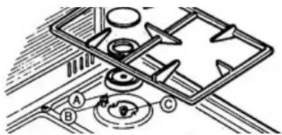
- remove the grids, covers, holed flame diffuser and the burner supports;
- replace the holed injectors as indicated in C according to the type of gas used (see table 1); put the burner supports, flame diffusers, covers and grids back in position;
• regulate the minimum output following the instructions in paragraph.
3.9 REGULATING THE MINIMUM OUTPUT OF THE BURNERS
Normal/valve taps
Ignite the burners and turn the know to the maximum position. Remove the knob and insert a small flat-head screwdriver into the holes on the side of the control panel, in accordance with the type (fig. A). Loosen the by-pass screw by two turns in an anti-clockwise direction and rotate the rod to the minimum position.
Adjust the previously loosened screws until the flame is lowered but stable, even when rapid changes are made from the maximum to the minimum position with the burner cold. If safety taps are fitted, let the burner run on minimum for a few minutes to ensure that the device does not cut in. If it does, increase the minimum.
N.B.: For liquid gas settings, the burner minimum must be set by fully tightening the tap by-passes.
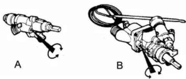
natural_image
Two mechanical diagrams labeled A and B showing different types of tools or components with rotating arrows (no text or symbols present)3.10 CONVERTING THE GAS-SUPPLY TO THE OVEN BURNERS AND GAS GRILL
Oven burners:
To have access to the oven injector proceed as follows:
- open the oven door and remove the oven base;
- unfasten the screw that secures the burner to the inside of the oven (in the giant oven it is fixed to the side wall of the muffle) and remove the burner from its seat being careful not to damage the thermocouple fixed to it;
- replace the holed injector in accordance with the type of gas used.
- put the burner back into its original position.
Setting the oven thermostat minimum
To set the minimum, proceed as follows:
- open the over door;
• light the oven burner and set it to maximum, close the door and wait for about 10 minutes (or the time required for the oven to heat up to about 230°C); - remove the oven knob and, using the hole in the control panel, according to the thermostat type, loosen the by-pass screw of the thermostat by two turns;
- replace the knob and turn it to the minimum position, remove the knob and adjust the previously loosened screw until the flame is lowered but stable, even when rapid changes from maximum to minimum are made and the oven door is opened or closer quickly.
N.B.: For liquid gas setting, the oven burner minimum is set by fully tightening the thermostat bypasses.
Gas grill burners
To convert the gas to this type of burner, see the “oven burner” instructions above. The only difference is that the burner is in the top of the oven, and there is no need to set the minimum because the burner always works at full power.
4. MAINTENANCE
WARNING:
Before carrying out any maintenance or conversion operations, turn off the electricity supply and close the gas upstream of the appliance. If components and/or accessories need replacing, use only Lofra spare parts only. All the operations hereunder must be carried out by qualified technicians in accordance with the enclosed instructions and current installation standards.
4.1 GAS SUPPLY RUBBER PIPE
The condition of the gas supply pipe should be checked periodically (once a year) and replaced by the date printed on the outside of the pipe and if there are signs of cracking, cuts, scratches or burns, or if it is no longer flexible but hard and plastic.
The pipe must be suitable for use with liquid gas and comply with the applicable standards.
4.2 ELECTRICITY SUPPLY CABLE
If the electricity supply cable needs replacing, therefore only authorised LOFRA technicians may replace it. Use HO5FVV-F cables only.
he earth wire (yellow/green) must be at least 2 cm longer than the other two phase wires.
This ensures that the electrics are safe should the wire be pulled accidentally.
For the cookers with a gas oven and an electric grill, use a 3x1.5 mm ^2 HO5RR-F cable, for cookers with electric oven and grill, use a 3x1.5 mm ^2 HO5VV-F cable with a maximum external diameter of 9 mm. In the case of current exceeding 16A shall have the power section 2.5 mm ^2 .
natural_image
Line drawing of a person using a tool on a curved surface, labeled A (no text or symbols present)4.3 REMOVING AND FITTING THE OVEN DOOR
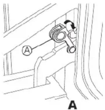
Open the oven door completely, insert the anti-rotation device (A) in the hook of the hinge rods. Hold the oven door by the sides and slowly close it until you can feel a certain resistance; simultaneously lift the door and force it towards its closed position in order to slide it out by freeing the hinge lock from the kitchen's body. To refit the door repeat the above instructions in reverse making sure the hinge lock is correctly fitted.
For the CURVA models insert an anti-rotation hinge in the appropriate holes. Hold the door by the sides and slowly close it until you can feel a
certain resistance; now, while forcing the door closed, lift it in order to slide it out by freeing the hinge lock from the kitchen. To refit the door repeat the above instructions in reverse making sure the hinge lock is correctly fitted.
Avoid using abrasive materials or any kind of sharp metal scraping tool to clean the glass oven doors to prevent them from getting scratched or cracked.
4.4 REPLACING THE LIGHT BULB
Turn the cooker off at the mains before replacing the bulb.
Open the oven door, remove the protective glass cover, replace the light bulb (CAUTION: it must be resistant up to 300°C) and replace the glass protection.
4.5 GLASS COVER
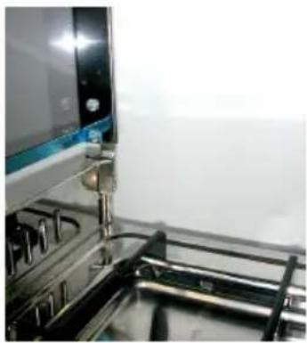
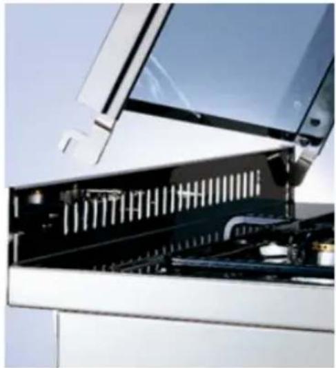
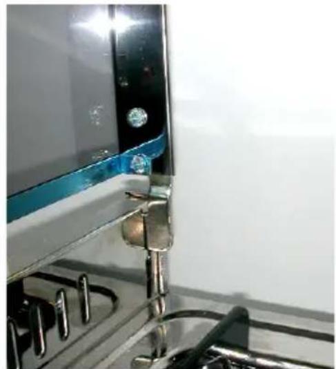
To assemble the cover put the hinges into the special spaces in the wall protection of the co-oker fitting into the existing slits (A), lift the co-ver up in vertical position (B) and push down until the hinges go to their place (C).
To disassemble the cover make the contrary of the above-described operation.
A
natural_image
Close-up of a white appliance with a black ventilation grille and mechanical components (no visible text or symbols)B
natural_image
Close-up of a stainless steel kitchen appliance with metal hinges and a blue trim (no visible text or symbols)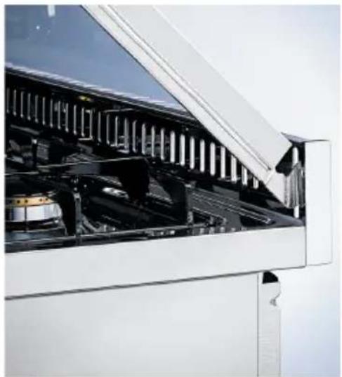
natural_image
Exterior view of a modern office building (no signage)C
5. USING THE COOKER
WARNING:
- If the burner flames accidentally go out, turn off the KNOB and wait for at least one minute before igniting.
- Using a gas cooker produces heat and humidity in the room where it is installed. Ensure the room is well ventilated by keeping all the natural air vents open or by installing an extraction hood with flue pipe.
- Intensive or extensive use of the cooker could may require supplementary ventilation e.g. opening a window, or more efficient ventilation e.g. increasing the capacity of the mechanic ventilation, if installed.
- The front control panel has one or two lights, depending on whether the oven is gas or electric. If the cooker has a gas oven a green light will illuminate when a heated accessory is turned on (ELECTRIC PLATES, ROTISSERIE, ELECTRIC GRILL). If the cooker has an electric oven, there is a green light and also a yellow light, which turns on and off when the THERMOSTAT cuts in to regulate the oven temperature.
5.1 USING THE COOKING HOB
Gas burners
Automatic electronic ignition built into the knob: turn the knob to the maximum position push it in and the burner lights up automatically.

No gas supply (knob turned off)

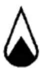
Minimum gas supply
Maximum gas supply
To obtain minimum supply, turn the knob in an anti-clockwise direction until the indicator points to the small flame
Safety device: once the burner is on, keep the knob pressed for at least 5 seconds and then release it.
The burner remains alight due to the thermocouple that keeps the gas flow by means of a safety valve, which shuts off the gas flow should the burner go out accidentally.
Burner performance: a variety of pans with a minimum diameter of 120 mm can be used on the "medium and small" burners.
The pans must not have concave or convex bottoms, but be perfectly flat as shows in figure. For optimum performance, use the saucepans shown in figure, i.e. the flames must not stay beyond the bottom of the pan.
When a liquid starts boiling, lower the flame as much as possible, but keep it on the boil.
For safety reasons, we recommend using pans with the following diameters on the various burners(see tables).
For emergency reasons we advise I use it of the following pots with diameters to overlap to the burners: auxiliary, semi-rapid, rapid, triple ring, fish burner.
| Burners Diameter | Min. (cm) Diameter Max. (cm) | |
| Small (auxiliary) 10 14 | ||
| Medium (semi-rapid) 15 20 | ||
| Large (Rapid) 21 26 | ||
| Triple ring (ultra rapid) 24 26 | ||
| Dual ∅ 145mm AEO four leaf 26 30 |
Note. To second of the conformation of the plan holding one distance between the edges of the pots of minimum 10mm.
Electric plates
The first time the plate is turned on or if it has not been used for a long time, it should be turned on and left on for 30 minutes in position 1 on the selector switch in order to dry out any humidity absorbed by the insulating cover.
To avoid heat dispersion and damage to the plate, use flat bottomed pans that have the same diameter as the plate, no more no less. Dry the bottom of the pan before putting it on the plate. When the plate is on, never stand an empty pan on it, or leave the plate on without a pan. Turning the plates on – centre the pan on the plate and turn the corresponding knob to the required position (see Table 2). The increasing numbers indicate greater power.
5.2 OVEN PERFORMANCE
Gas oven
The oven burner must always be ignited with the oven door open.
All Lofra cookers are fitted with valve thermostats which not only regulate the temperature inside the oven, but also stop the gas flow should the burner go out accidentally, thus avoiding leakage of unburned gas.
For the best results, we recommend preheating the oven for 10+15 minutes before putting the food in.
he oven door should be opened as little as possible in order to avoid any rapid changes in oven temperature, which may compromise the cooking results.
Ignition – open the oven door, press and turn the oven knob (symbol) in an anti-clockwise direction to the maximum position. The burner can be ignited with press into the knob.
When the burner alights, keep the knob well pressed in for 5+10 seconds and then release it.
The burner stay alight by heating the thermocouple that opens the safety valve and keeps the gas flowing.
After carrying out these operations, close the oven door and turn the knob to the required temperature.
The automatic ignition device (electronic ignition built into the knob) must not be activated for more in 15 seconds. If the burner does not ignite after this time, release the knob and wait for at least one minute before trying to ignite the burner again. In some models, a special safety device discharges electricity so that the burner only ignites when the door is open.
Electric ovens
STATIC OVENS: heat produced inside the oven by electric elements fitted in the top (sky) and bottom (base) of the oven; these elements can work together or independently. This gives more even cooking, for example when the cooking time is almost up, the food may need more heat at the top or the bottom.
The temperature is kept constant by the
thermostat, which can be set between 50 and 250°C.
During cooking, only open the oven door when strictly necessary. During this cooking method, humidity loss from the food is slow and uniform.
Fan oven
Heat is produced by the forced circulation of hot air inside the oven. A circular element next to a motorised fan heats the air, which this fan circulates evenly and rapidly.
Indeed, this type of oven cooks faster than traditional ovens, hence you should set your cooking temperatures 10-20°C lower than normal.
Once again the thermostat maintains the oven at the pre-selected temperature, which range from 50°C and 250°C.
The oven need only several dishes together without altering the flavours in any way.
Switching on the multiple-function oven: turn
the oven knob marked by the =orthe
symbol to the right and set the required temperature, in accordance with the cooking method.
Mixed ovens (gas/electric)
Certain models of cooker have both gas and an electric ovens. To switch on the oven, see the previous paragraphs detailing "gas ovens" and "electric ovens".
For safety reasons, they must be used separately.
USING THE GRILL
The food is laid on the oven grill, which then be placed inside the oven. The grill's position depends on the type of food, e.g. flat or thin meat should be placed on the level closest to the grill, while a roll of meat, or poultry, etc. should placed on the middle level.
The drip tray should be fitted on the guides below the grill.
Using the gas grill:
We recommend using the gas grill to complete oven cooking, therefore for 15-20 minutes at most; both for better cooking quality and for lower consumption and reduced cooking times. All the gas grills have a safety device that automatically stops the gas flow if the burner accidentally goes out, A special two-way thermostat activates the oven burner on the grill burner.
The gas grill cannot be regulated as it always works at maximum.
They can be turned on manually or elettronically; refer to the indications given for the gas oven burner.
During the operation of the oven the door must remain closed.
Using the elettrical grill:
a) MODELS WITH GAS OVEN: to avoid the oven and the grill being used at the same time, the oven knob must be set in the off position for safety reasons, i.e. at the • symbol.
Then press the electric grill button which is on the control panel.
b) MODELS WITH ELECTRIC OVEN: are switched on by turning the oven knob to the right (clockwise) until the indicator points to the grill symbol (last knob position).
c) MODELS WITH MULTIPLE-FUNCTION
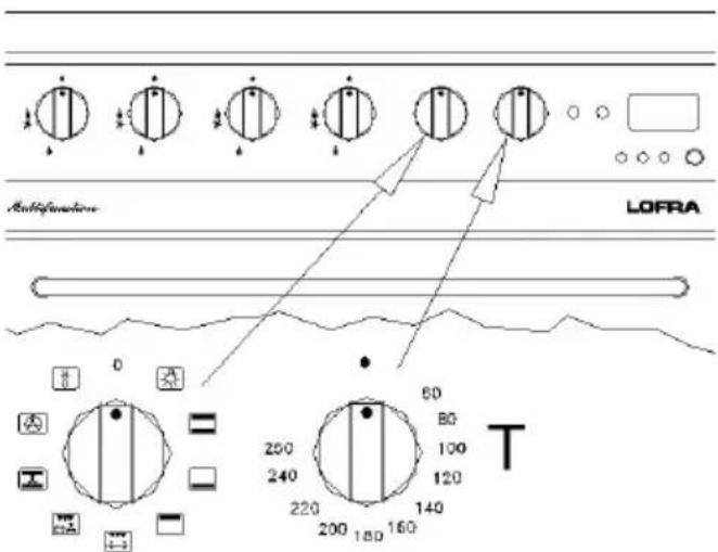
OVENS: switch on the grill by turning the functions knob to right (F) and set it to the
required grill position 📌. Then turn the oven thermostat knob (T) and set the temperature to 200°C. The oven door must stay closed.
d) MODELS WITH MULTIPLE FUNCTION
OVEN AND RADIATING GRILL: the grill cooks by
radiating heat, which is produced by a special element that reaches a temperature of approx. 800°C in a few seconds. It produces infrared rays which a transparent pyroceram plate used to ensure ultra-quick cooking times.
The layout of the heating filament and the high insulation level mean that heat distribution is concentrated on the surface of the pyroceram plate, thus ensuring even cooking and energy savings.
The plate should be cleaned once the oven has cooled down.
The plate can be cleaned more thoroughly and more easily, and it protects the heating element from splashes and fat.
e) MODELS WITH CHANGEABLE GRILL
Grill operation: switch on the grill by turning the function knob to the right (F) and set it to
required grill position.
Then turn the oven thermostat knob (T) and set temperature to 200°C, regulate the knob on
the changeable grill on the position MIN. - MED. - MAX. according to the utilization. The oven door must stay closed.
f) When turning the function knob to the right on the desired temperature, upper and lower heating elements are activated. If you turn it further you can decide which heating element to use.
Upper, lower or grill maximum temperature.
g) MODELS WITH GAS GRILL (..G2G.. e .. G2VG..)
Models with grill and gas oven with independent controls ...G2G... models
The grill gas is controlled by a know marked
by the symbol which can be used in
maximum position depending on the type of cooking. The simultaneous injection and use the grill with gas oven is possible only when the oven is functioning from at least 5 minutes. Best performances are reached when the grill is turned on at least 15/25 minutes before end of cooking
VENTILATED GAS COOKERS MODELS: ...96G2VG
In these models the oven cooking and with closed door can be:
• Static (oven or oven + grill without ventilator)
- Ventilated (oven or oven + grill with ventilator)
OVEN + FAN GRILL (VENTILATED)
Light first the oven as indicated in the point 3.2 of the manual. After 5 minutes light the grill and regulate it on the max position. After at least 5 further minutes switch on the fan.
WARNING
By simultaneous work of oven + grill, fan must not be used in the models G2VG adjusted with G20 (natural gas).
text_image
Multifunction LOFRA 0 60 80 100 120 T 250 240 220 200 180 160ATTENTION: Only on models ..G2G.. grill gas and gas oven can be used together. If the pyroceram plate brakes, turn off the power supply and call your Authorised Lofra Service Centre.
If the surface of the grill is cracked, switch off the switch to the appliance to avoid the possibility of electric shock.
The accessible parts get very hot when the grill is in use. Keep children at a safe distance.
5.3 ROTISSERIE (ONLY CERTAIN MODELS)
The rotisserie is used for spit-roasting using the oven and the grill.
After placing the drip tray on the bottom shelf, follow these procedures:
- fit the handle to the spit, skewer the food onto the spit and secure it at either end with the two adjustable forks (to avoid the rotisserie motor overworking, try to distribute the food on the spit as evenly as possible);
- place the spit rod into the support and then into the motor shaft;
- loosen the split handle and start the motor with the switch on the front control panel; then turn on the grill.
5.4 MINUTE TIMER
This mechanical minute timer goes from 0 to 60 minutes and sound a bell when the preset time is up. To start the timer, turn the knob to the right and set it to the required time.
The knob automatically returns to zero, and the bell rings at the end of the preset time.
Warning: the knob must not be turned in anti-clockwise besides the hand symbol, otherwise you can break the timer.
5.5 MULTIPLE-FUNCTION COOKERS
The multiple function cookers are distinguished by the fact that the heat, inside the oven, can be spread naturally (convection) or forced (with the fan).
Thanks to this, by turning the selector to the desired function, 8 different types of cooking with separate temperature (thermostat knob) regulation are possible between 50 and 250°C; therefore even the most varied cooking requirements are satisfied.
Depending on the models, these cookers have an end of cooking timer or a digital electronic programmer.
Cookers with timer:
Cookers with this device allow uninterrupted manual working and programming the cooking time of the oven between 0 and 120 minutes.
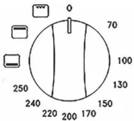
Uninterrupted manual working: set the type of cooking and the oven temperature using the "A" and "B" knobs respectively, turn the timer knob "C" in an anti-clockwise direction until it
coincides with the symbol.
text_image
0 70 100 130 150 170 200 220 240 2505.6 ELECTRONIC PROGRAMMER
Lofra new electronic programmer is a high-technology component which, by using only one knob, allows to use all the functions that usually are made with more than one knob.
Beyond to turn in clockwise and anti-clockwise direction, it can be pressed as a push button. This simple system easily allows to use all the cooking programmes of your new cooker.
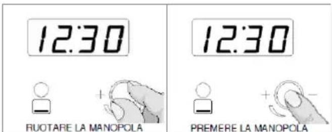
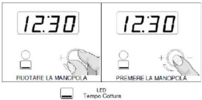
To make easy the explanation of the functions next to the text you will find a descriptive Image about the operation that you will have to carry out.
text_image
12:30 RUOTARE LA MANOPOLA 12:30 PREMERE LA MANOPOLA
LED
Tempo Cottura
At the moment of the first ignition the display blinks.
How to program time at the first ignition of the system.
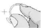
Turn the knob and program hour and minutes.
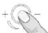
Confirm pressing completely the knob.
How to regulate the hour.
To modify the hour after the first time, keep pressed the knob for 3 seconds, and carry out the previous operation.
Minute counter function.
Turn the knob to program the times of the “minute counter”. The display shows the remaining
time and the led blinks, at the end the display shows "END" and a sound warning is in function.
The sound alarm is repeated for 10 minutes.
It is intermittent in the first 30 seconds, after you can hear a warning every 15 seconds. To interrupt press the knob.
Turning the knob in clockwise direction a new count is in function again and you have the possibility to modify the time.
To interrupt the function you have to turn the knob until 0 or to press the knob.
Cooking time function.
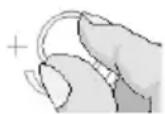
Turning the knob with the lighted oven the function "cooking time" is activated,
the led blinks and the remaining time is showed.
When on the display " END"
appears, the oven switches off and a sound warning is in function.
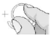
To come back to the hour press the knob or put the oven knob in off position.
Turning it to right a new count is in function again, the oven switches on and it is possible to program a new time too.
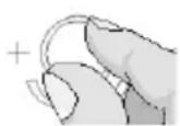
To interrupt the function turn the knob until 0 or press the knob.
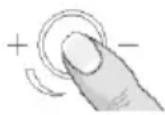
To connect a “minute counter” function during the cooking with the lighted oven and “cooking time” not connected, to be advised without the switching off of the oven, it is sufficient pressing the
knob 2 times, the "minute counter" function is on with a pre-programmed time of 5 minutes.
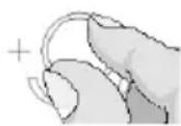
It is possible to modify the time operating on the knob.
Note: If the knob is pressed twice consecutively it is possible to regulate the timer at intervals of 5 minutes. Push once more to fix the desired time.
Function “ cooking programming” with delayed starting.
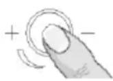
Pressing the knob with the switched off oven, the function "cooking programming" is on, the
STOP blinking led switches on, you program the hour of automatic lighting with the knob and you
confirm it pressing.
Turning the knob to program the cooking time, the two leds blink.
Press the knob to come back to the hour, the programming has finished.
The programming led 1 blinks to indicate that the function is on. After you can program the desired function and temperature of the oven operating on the knob.
At the programmed hour, the oven switches on, the display starts to visualize the remaining
cooking time and the led blinks.
At the end it switches off and "End" is visualized, followed by sound signals.
Warning: the function is not on if you try to program a null cooking time or the starting hour is the same as the actual hour. The programming has to be made by 1 minute, otherwise the function ends. If the oven is switched on, it is deactivated at the end of the configuration.
If you want to continue the cooking, turn the knob to program the new hour.
Note: With a programmed starting, the function remains memorized, even if the power goes away. The oven will switch on with a delay equal to time for which power has lacked.
ELECTRONIC PROGRAMMER for cookers with "gas oven ventilated".
text_image
12:30 RUOTARE LA MANOPOLA 12:30 PREMERE LA MANOPOLA LED Tempo CotturaHow to program time at the first ignition of the system.
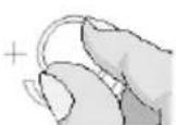
Turn the knob and program hour and minutes.
Confirm pressing completely the knob.
How to regulate the hour.
To modify the hour after the first time, keep pressed the knob for 3 seconds, and carry out the previous operation.
Cooking time function.
Turning the knob with the lighted oven the function "cooking time" is activated,
the led -blinks and the remaining time is showed.
When on the display "END" appears, the oven switches off and a sound warning is in function.
To come back to the hour press the knob or put the oven knob in off position.
Turning it to right a new count is in function again, if oven switches on is possible to program a new time too.
To interrupt the function turn the knob until 0 or press the knob.
Note: If the knob is pressed twice consecutively it is possible to regulate the timer at intervals of 5 minutes. Push once more to fix the desired time.
ATTENTION: it is forbidden leaving inside the oven not working something different from pats.
text_image
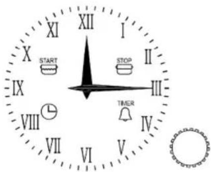
XI X START IX VIII VII XII I STOP II III IV V TIMERCOOKING PROGRAMMER
HOUR ADJUSTMENT
In order to adjust the hour on the clock, push 4 times the knob until the icon "CLOCK" blinks. To increase or decrease the time, turn the knob clockwise or anticlockwise, the minute hand will move in one-minute intervals.
After 10 second from the last regulation the timer will set up automatically.
MANUAL COOKING
When off, the timer allows the manual cooking by pressing the general button of the oven.
END COOKING PROGRAMMATION
Programming the end cooking time allows starting and finishing the cooking in an automatic way according to the programmed hour.
To program the end of the cooking, briefly push the knob twice until the "STOP" icon flashes.
To increase or decrease the cooking time turn the knob clockwise or anticlockwise until the desired time is reached.
The flashing of the "STOP" icon continues for 10 seconds from the last setting, if by this time the programming isn't made, the function ends and the hands will return to display the time.
Push the knob to confirm the program (at least 2 minutes) so the cooking can start. To display the selected program push the knob quickly.
At the end of the cooking the "STOP" icon will flash and the alarm will beep. After 1 minute the alarm will be disabled, but the "STOP" icon will keep on flashing until the knob is pushed.
To stop the program before the settled time, push the knob for 3 seconds: the program will be deleted and the timer will return to the manual cooking set up.
START COOKING DIGITAL PROGRAMMER
Programming the start cooking time allows to automatically start and stop the cooking.
To program the start cooking time, briefly push the knob until the "START" icon flashes.
To increase or decrease the start cooking time, turn the knob clockwise or anticlockwise.
The flashing of the "START" icon continues for 10 seconds after the last setting.
If by this time the programming isn't made, the function ends and the hands will return to display the time.
If the knob is pressed the cooking start time is set (at least 1 minute) (the "START" icon is lit on and steady). The next step is the setting of the end cooking time (the "STOP" icon starts flashing).
To program the end cooking time follow the procedure below.
The two icons "START" and "STOP" will remain on to indicate successful programming.
TIMER PROGRAMMING
The timer programming allows to set a simple alarm at the end of a programmed time without starting up the cooking.
To set an alarm, press briefly the knob three times until the icon "TIMER" stars flashing.
Then turn the knob, the timer programming is identical to the end cooking time program (see the relevant paragraph)
The timer can be used only when there is no ongoing function.
DISPLAY OF THE SELECTED PROGRAM
To display the selected program briefly press the knob, at the same time the programmer displays the program moving the hands on the selected time. The flashing of the relevant icons indicates the different phases.
The programmer will then return automatically
to display the current time and the execution of the selected program.
DELETION OF THE SELECTED PROGRAM
To delete the selected program, push the knob for some seconds until you hear a beep and the relevant icons are off.
The programmer will then return automatically to the manual cooking mode.
BLACKOUT SIGNAL
The timer does not cancel the program in case of blackout.
The timer signals any lack of power supply through the flashing of the "CLOCK" icon, in order to verify that the time is set correctly.
In this case, to disable the alarm quickly press the knob.
5.8 LIST OF FUNCTIONS MF AND MFR

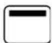
Conventional oven.
The heat distributes evenly from the top and the bottom. Ideal for baking patries, cakes & biscuits and roasts. Recommended for cooking individual items.
Cooking from below.
The heat distributes from the bottom to give cooked food a finishing touch.
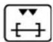
Cooking from above.
The heat comes from the top (sky) heating element. Ideal for cooking the top of dishes without grilling.
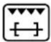
Grilling or rotisserie (\*).
The heat is radiated in the oven. Ideal for grilling, browning, and au gratin dishes.
Maxi-grill and rotisserie (\*).
Like function 5, but with higher power and a larger radiating surface.
Maxi-grill with fan-assisted oven and rotisserie (\*).
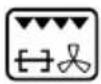
The heat is radiated in the oven and is a evenly distributed by the fan. Ideal for browning food without drying them out.
Even cooking.
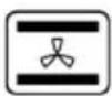
The heat emitted by the top and bottom heating elements is distributed by the fan for quick, even cooking, inside and out. Recommended for cooking individual items.
Fan-assisted cooking
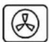
The heat is distributed by forced ventilation. Ideal for food that has to be well-cooked in the middle and not well-done on the outside. This cooking
system enables you to cook three different dishes at the same time. Super fast defrosting Set the switch to "fan-assisted cooking" and the thermostat to 50°C in order to defrost food in no time at all.
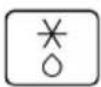
Defrosting
Set the oven thermostat to "0" position. Food can be defrosted by using the fan without any heat.
(*) ONLY CERTAIN MODELS

Oven light.
Conventional oven.
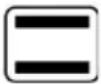
The heat distributes evenly from the top and the bottom. Ideal for baking patries, cakes & biscuits and roasts.
Recommended for cooking individual items.
Even cooking.
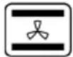
The heat emitted by the top and bottom heating elements is distributed by the fan for quick, even cooking, inside and out.
Recommended for cooking individual items.
Grilling.

The heat is radiated in the oven. Ideal for grilling, toasting, browning, gratin dishes.
Grilling with fan-assisted
oven.
The heat is radiated in the oven and evenly distributed by the fan. Ideal for grilling, toasting, browning, gratin dishes, etc. without the inside of the food drying out.

Cooking from below.

The heat distributes from the bottom to give cooked food a finishing touch.
1. MODELS WITH GAS OVEN AND GRILL
GRILL
For best results preheat for approximately three minutes with open door. In the event of the burner flames being accidentally extinguished, turn off the burner control and do not attempt to re-ignite the burner for at least one minute.
OVEN
If both the ovens are working simultaneously, please light the Up oven and after at least 3 minutes the oven down.
For perfection we recommend preheating the oven for about 15 minutes at the gas mark you require for cooking.
Never place dishes on the oven base over the burner.
Never cover the oven interior with Aluminium foil!
In the event of the burner flames being accidentally extinguished, turn off the burner control and not attempt to re-ignite the burner for at least one minute.
2. MODELS WITH ELECTRIC/MULTIFUCTION OVEN
Operating (read the table below).
Oven Down | |
Oven Up Trad | cooking with heat propagation from above and from below. With the same knob is possible to set the temperature till a maximum of 260°. |
 | Cooking from below with a maximum temperature not over 260°C; this position is ideal for cooking with sauces. |
 | Cooking from above with maximum temperature fixed on 260°; this position is ideal for soft cooking (grating) and grilling (toasted bread). |
 | Cooking from above with maximum temperature fixed on 260°; this position is ideal for fast grilling (red meat) or gratin dishes |
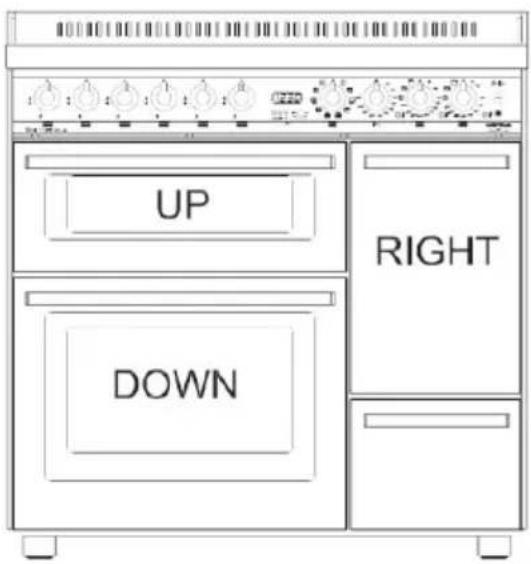
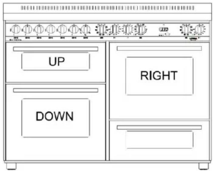
CUCINA CON DIMENSIONI 96 E 126 A 3 FORNI ELETTRICI
text_image
UP DOWN RIGHT90 × 60 120 × 60
text_image
UP DOWN RIGHTThe cookers of 90x60 three ovens have 1 oven of 60 of liters and 2 ovens of 30 liters, with electric heaters.
The cookers of 120x60 three ovens have 2 ovens 60 of liters and 1 oven of 30 liters
| Models | Base Resistance | Sky Resistance | Grill Resistance | Maxi- grill Resistance | Circuit Resistance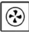 | |
| 3 ovens size 90 | Oven down 60 l | 1650 W 900 | W 1500 W 2400 | W 2000 W | ||
| Oven up 40 l | 1200 W 250 W 19 | 00 W | ||||
| Oven right 30 l | 1200 W 500 | W 1000 W | ||||
| 3 ovens size 120 | Oven down 60 l | 1650 W 900 | W 1500 W 2400 | W 2000 W | ||
| Oven up 40 l | 1200 W 250 W 19 | 00 W | ||||
| Oven right 60 l | 1650 W 900 | W 1500 W 2400 | W 2000 W | |||
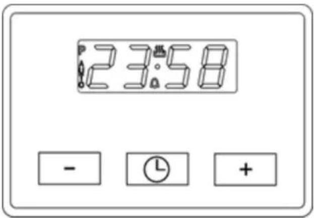
text_image
23:58 - ⓕ +SETTING THE CLOCK
"Auto" and "0:00" will start flashing when the unit is switched on for the first time. To set the clock, press the central button for about 3 seconds.
When appears, press "+" or "-" to set the correct time.
Wait until a beep tells you that the clock has been set (figure 1).
To set the time at a later stage, press "+" and "-" together for 3 seconds and then adjust the clock as described above.
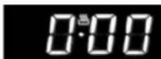
MINUTE COUNTER
As this minute counter does not control the oven, when it finishes counting the oven will continue to work.
To set, press the central button for 3 seconds until appears (figure 2). Press "+" and "-" to set the required time.
To set the minute counter at a later stage, press the central button for 3 seconds and adjust as described above.
The minute counter beeps when it finishes counting. To disable it, press any button.
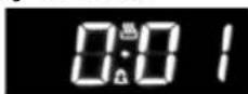
COOKING TIME
This is a semi-automatic cooking function. It can be used to set cooking times.
Press the central button for 3 seconds. Then press it again until "dur" appears (figure 3). Press "+" and "-" to set the required cooking time.
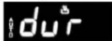
END OF COOKING TIME
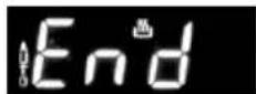
The end of cooking time can also be set. Press the central button for 3 seconds. Press the central button twice consecutively and wait for "End" to appear (figure 4). Press "+" and "-" to set the required end of cooking time.
The oven will work in the set mode and at the set temperature until the end of cooking time.
PROGRAMMING AUTOMATIC COOKING
Cooking function with set times.
Press the central button for 3 seconds. Then press it again until "dur" appears. Press "+" and "-" to set the required cooking time. Wait a few seconds for the setting to be memorised. Press the central button for 3 seconds. Press it another two times and wait for "End" to appear (figure 4).
Press "+" and "-" to set the required end of cooking time.
E.g.:
- Current time: 12.30
• Cooking time: 10 minutes
• End of cooking time: 14.00
• The oven will start cooking at 13.50 (14.00 less 00.10) at the set temperature and in the set mode and will stop at 14.00
• The oven will beep when it stops cooking. To disable it, press any button.

text_image
dur EndADJUSTING BEEP VOLUME
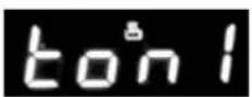
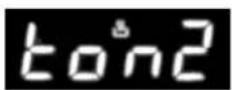
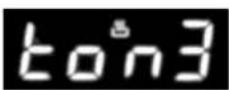
To adjust beep volume, press "+" and "-" together. Then press the central button and wait for "ton1" (high volume) to flash. Press "-" to select "ton2" (medium volume) or "ton3" (low volume).
Press the central button to set the selected volume.
5.11 VITROCERAMIC COOKING HOB (APPLICABLE MODELS ONLY)
Switching on
The control is switched on by pressing (x sec.) the on/off key a beep sounds.
It will not come on if the key lock function is activated (indicated by a pilot light). The heaters remain off (all the digits show 0) until a power level is selected. If the selection is not made in 10 seconds, and if the timers are off, the control turns off automatically.
Selecting a power level for a certain heater
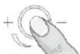
With the control on, the first time the sensor (+) is pressed (x sec), the heater switches on at level 1 by default (configurable).
The sensor (+) raises the cooking level to a maximum of 9, whereas the sensor (-) reduces the cooking level to 0 (heater off).
With the heater at position 0, the sensor (-) raises the cooking level to 9.
If the sensor is held down, the action is repeated twice every second.
Activating the heat-up function
This function takes the cooking level to maximum power for a defined time.
The heat-up function is activated selecting the power level 9, and touching the (+) key. The decimal point of the display blinks for 10 seconds.
During these 10 seconds the desired power level must be selected (between 1 and 8). After this time a beep sounds, and the decimal point remains fixed, indicating the heat-up function is ON. If the power level is 0 or 9, the heat-up function is cancelled.
If the heat-up function is activated, pressing the heater (+) key, the duration of the heat-up function will be the duration for the new power level; if the new level is 9, the heat up function is cancelled.
The Heat-up function can be cancelled either automatically, when the time expires, or when the user wishes.
When the heat-up function is cancelled automatically, a beep sounds, the decimal point of the display turns out, and the power level of the heater remains the selected power level. If we press the (-) key when the heat-up function is activated, the function is cancelled.

text_image
8* -88+ -8**| Power Level Time (sec.) | |
| 1 1'12" | |
| 2 2'44" | |
| 3 4'48" | |
| 4 5'28" | |
| 5 6'30" | |
| 6 1'12" | |
| 7 2'44" | |
| 8 2'44" | |
Key loc
Holding the key lock sensor down turns the key lock function on or off. If the pilot light associated with the
key lock sensor is on, the keypad is locked.
The locking function can be activated when the cooking levels are activated or when the cook top is off. If the cook top is on, the key lock function locks all the sensors except the general on/off sensor and the key lock. When the cook top is off, the key lock function locks all the sensors, including the general on/off, except the key lock.
Unlocking the keypad
If the keypad is locked (the pilot light associated with the key lock sensor is on), holding down the key lock.
Sensor turns the key lock function off and the pilot light goes off.
Residual heat for radiant heaters
While a temperature on the cook top glass surface is above 65^ C, this condition will be shown in the
associated display, by means of an "H".
If the cook top is switched off, the residual heat is shown by a static "H" in the display. If the cook top is on, but the power level is 0, the associated display will show alternately "H" and "0".
Operating the timer
The timer is activated by pressing the timer keys
(+) or (-) up to the big central symbol. The timer value can be selected between 1 and 99 minutes, and can be modified at any time. To cancel the operation of the timer, select a timer value of <00> using the sensor (-), or switch off the timer by pressing the corresponding sensors (+) and (-) at the same time.
Heater on timer
This can be any of the touch-control heaters. When the timer value runs out, the heater associated with the timer switches off.
The heater associated with the timer can be can be selected.
Selectable heater
The user can select the heater on which the timer function is to operate. The
selection of a new heater disables the previous selection in such a way that the timer only operates on
one heater each time.
The heater must always be selected before the
time is set; otherwise, the timer will switch off. If we take longer than 10 seconds to select the heater, the timer will switch off.
If, after selecting the heater, the time is not defined (T=00) in 10 sec., the timer switches off. It is possible for the user to time a heater at power 0.
If the configuration permits Alarm-mode, instead select a heater, the user touches again the timer in the heater selection periode, it goes to minute-minder mode and at the end of time will not switch-off any heater.
In Alarm-mode, the dot of the timer display doesn't light.
Indication of the heater on timer with "t" on the heater display.
The touch control indicates the heater on which the timer is operating. This indication consists of a "t"
blinking with the power level in the display of the heater., 5sec every 15 sec. Also if the user changes the value of the timer, the "t" blinks.
This option reminds the user at all times that the heater is on timer.
Indication of the heater on timer with Led
(small symbol)
The touch control indicates the heater on which the timer is operating. This indication consists
of a LED (small symbol) next to the double display of the heater on timer.
This option reminds the user at all times that the heater is on timer.
Increasing the value of the timer
If the sensor (+) or (-) associated with the timer is held down, the value increases/decreases automatically.
This makes it possible to reach the desired timer setting more quickly. From the tenth consecutive increase/decrease of the timer setting, the speed at which the value changes increases.
Duration of the warning
When the time set on the timer has run out, a
beep sounds for 1 minute, or indefinitely (this option is also configurable), and the timer displays flash the indication <00>
o 1-minute alarm: After 1 minute from when the timer alarm starts, the beep stops. The timer displays
continue to flash with the indication <00>. The alarm can be cancelled by the user at any time, even
during the first minute of the alarm, by pressing any sensor on the touch control.
o Indefinite alarm: The beep does not stop until the alarm is cancelled by the user. It can be cancelled by pressing any of the sensors on the touch control.
Auto power-off
If the power level is not changed during a preset time, the corresponding heater turns off automatically.
The maximum time a heater can stay on depends on the selected cooking level.
| Power Level | Max. Time on Hours |
| 1 | 10 |
| 2 | 5 |
| 3 | 5 |
| 4 | 4 |
| 5 | 6 |
| 6 | 2 |
| 7 | 2 |
| 8 | 2 |
| 9 | 1 |
5.12 GLASS CERAMIC WORKTOP
The new design concept heating elements make it possible to reach maximum power in a few seconds. Furthermore, the ultra-thick fibreglass insulation prevents heat dispersion, limiting heating to the silk screen-printed zones only.
The 4 (or 5) heating zones are controlled by 2 switches and 2 (or 3) energy regulators.
The switch controls power in W, which is pre-defined according to the position set on the
knob.
The energy regulator is a device which regulates power gradually according to the position set on the knob ( % of maximum power). Control of the heating zones is automatic, by activating or disabling the heating elements at regular intervals, thus ensuring precise, uniform heating.
E.g.: short heating periods and long pauses
| Cooker Model | Base Resistance Sky Resistance Grill Maxi Grill Circuit Resistance | ||||
 |  | 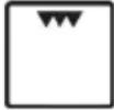 |  |  | |
| MXV66MFR - MXV76MFR - PXV66MFR - PXV76MFR | 1900W 700W | 800W 2500W 200W | |||
| PXV66MFR - PXV76MFR 1750W | 1000W 2000W 3000W | 2500W | |||
| MXDV96AMFRE-PXDV96AMFRE- STANDARD OVEN | 1900W 700W | 800W 2500W 2000W | |||
| MXDV96AMFRE- PXDV96AMFRE- SMALL OVEN | 1200W 500W | 1000W | - | ||
| MXUDV66AMFE - MXUDV76AMFE - PXUDV66AMFE- .UDV66MFE DOWN OVEN | 1650W 900W | 1500W 2100W 2000W | |||
| MXUDV66AMFE - MXUDV76AMFE - PXUDV66AMFE- .UDV66MFE UP OVEN | 1200W 950W | 1900W | - | ||
indicate low temperature; long heating periods and brief pauses indicate a higher temperature. With the energy regulator, you can totally or partially heat a particularly zone of the glass ceramic top.
Plate lay-out (see tables)
| Characteristics of the heating zones in 4 heating plate kitchen ranges. | ||||||||||
| Position | Type Of Command | Effective Heated Zone | Knob Rotation | Max. Power | Knob position and relevant power | |||||
| 1 2 3 | 4 5 6 | |||||||||
| Front Left | Energy Regulation |  | All Clockwise 220W | 10% 25 | 50% 65% 90% | 100% | ||||
 | Circular | Anti-clockwise | 750W | |||||||
| Rear Left | Switch All | [3HS6] | Anti-clockwise | 1200W 15 | 0W 200W | 350W 500W 850W | 1200W | |||
| Front Right | Switch All |  | Anti-clockwise | 1700W 18 | 0W 300W | 450W 750W 1200W | 1700W | |||
| Rear Right | Energy Regulation |  | All Clockwise 2400W | 10% 25 | 50% 65% 90% | 100% | ||||
 | Circular | Anti-clockwise | 1500W | |||||||
| Characteristics of the heating zones in 5 heating plate kitchen ranges. | ||||||||||
| Position | Type Of Command | Effective Heated Zone | Knob Rotation | Max. Power | Knob position and relevant power | |||||
| 1 2 3 | 4 5 6 | |||||||||
| Front Left | Energy Regulator |  | All Clockwise | 220W | 10% 25 | 50% 65% 90% | 100% | |||
 | Central | Anti-clockwise | 750W | |||||||
| Front Right | Switch |  | All | Anti-clockwise | 1200W 15 | 0W 200W | 350W 500W | 850W | 1200W | |
| Rear Right | Switch |  | All | Anti-clockwise | 1700W 18 | 0W 300W | 450W 750W | 1200W | 1700W | |
| Rear Left | Energy Regulator |  | All Clockwise 2400W | 10% 25 | 50% 65% 90% | 100% | ||||
 | Central | Anti-clockwise | 1500W | |||||||
| Central | Energy Regulator |  | All Clockwise | 200W | 10 | 25% 50% 65% 90% | 100% | |||
| [WW2C] | Central | Anti-clockwise | 1100W | |||||||
Residual heat
The glass ceramic top is divided into4 (or 5) heating zones. To ensure extra safety, it has indicator lights (residual heat indicators), which light up when a zone is very hot.
The indicators stay lighted for as long as the heated zone remains hot, even with the plates OFF.
How to use the glass ceramic top
When using the top for the first time, we advise you to turn ON the heating zones one at a time for few minutes, in order to eliminate any humidity accumulated in the insulation.
To avoid heat dispersion and for excellent performance, we advise you to use pots with a flat, thick bottom.
Furthermore, whenever possible, the pots should be of the size as the heating zone being used.
The heated zone stays hot for a certain period of time. You should therefore exploit this by switching the plate off a few minutes before end of cooking, so that you finish cooking by exploiting the residual heat accumulated by the glass, and save on energy.
We advise you to clean when the glass has cooled. Wash the glass with the type of liquid detergent as per supplied sample, or with soapy water.
For stubborn dirt, use the supplied scraper. Do not use abrasive material such as Scotch bryte, metal sponges or the like.
Take care not to spill sugar while cooking, because impossible to remove deposits could be formed.
Any cast-iron pots or with a rough bottom tend to leave light coloured traces, which can be removed with a cloth dampened with vinegar.
WARNING:
when the top is in operation or the residual heat indicator is ON, take great care, and keep children away.
Accessible parts of the oven can become very hot while the grill is operating. Children should be kept at a safe sistance.
If the glass ceramic breaks, disconnect electric power and call in the Lofra Authorised Service Centre.
5.13 FITTING THE FAT FILTER TO GIANT MULTIPLE FUNCTION OVEN
- Place tabs A-B in line with the holes in the fan cover A1-B1 at back of the oven.
- Press rod C so that the tabs fit perfectly into the holes A1-B1.
Fitting the gas burners to the hob
Burners: auxiliary, semi-rapid, rapid, super rapid:
- To fit the burners, flame diffusers and the enamel burner caps correctly in the hob cups, follow the sequence illustrated in figure. Ensure that the cup burner guides and the burner flame diffuser guides are matched perfectly.
- Treble crown burner: fit the flame diffuser to the burner support so that it cannot rotate.
| LAY-OUT FOR CONNECTING KITCHEN GLASS CERAMIC WORKTOP | ||
| 220 - 240 V ~ 3 x 6 sq.mm H05VW-F | 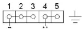 | |
| 380 - 415 V 3N ~ 5 x 2.5 mmq H05VW-f | 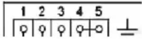 | |
ATTENTION: the treble crown burner caps must always sit perfectly in their seats. If they are not, the flame may return inside and deform the burner by progressive overheating.
Fish kettle: fit the flame diffuser by placing the hole in the bottom part over the electronic ignition candle in the hob cup.
5.14 TELESCOPIC RUNNERS (ONLY FOR CERTAIN MODELS)
The telescopic runners guarantee greater stability to the oven accessories. Placing the food on the shelves or on the tray is easier and safer.
The shelves and trays must be securely fitted into their housing on the runners.
We recommend using oven gloves during cooking or while the oven is still hot.
5.15 TRAY WITH ANTI-FALL DEVICE
The tray are equipped with safety system to prevent its extraction out of the oven.
Inserting check that the anti-fall device (see picture) is always in the back.
The tray are extracted from the oven only if raised before.
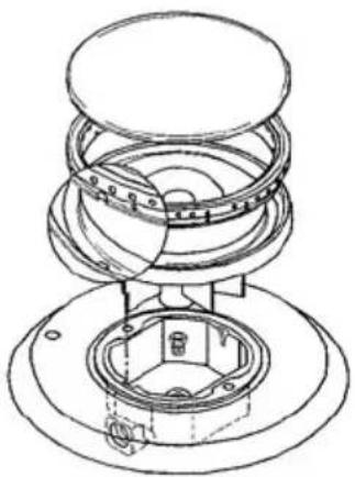
natural_image
Technical line drawing of a mechanical assembly with layered components (no text or symbols)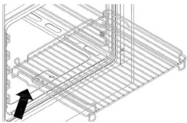
natural_image
Technical line drawing of a rack structure with an arrow indicating direction (no text or symbols)5.16 GAS BURNER SERIES III - FITTING INSTRUCTIONS
The gas burner cap must be placed on its seating and turned clockwise making sure the two fitting marks face the pins of the below flame-spreader (as shown in the picture).
WARNING
An incorrect fitting of the gas ring could cause the flame to spread inside the gas jet itself damaging it.
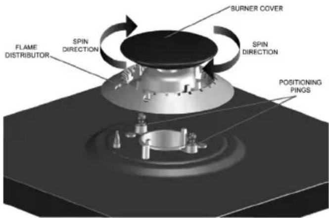
text_image
FLAME DISTRIBUTOR SPIN DIRECTION SPIN DIRECTION BURNER COVER POSITIONING PINGSGLOW PLUGS OPERATING INSTRUCTIONS (ONLY ON SELECTED MODELS)
To switch the gas jets on press the knob and turn it anti-clockwise; the glow plug will turn bright red and cause the gas jet's flame to light.
WARNING
It is recommended not to leave any inflammable materials on top of the kitchen's work surface, such as cloths and grease proof paper, which could catch fire just by pressing the knob, even when the gas jets are switched off.
Make sure every precaution is taken; by pressing the knobs the glow plugs will immediately turn on and reach 1300^ in temperature.
The glow plugs must not be knocked to avoid damaging them.
TO AVOID BURNS AND INJURIES THE GLOW PLUGS MUST NOT BE TOUCHED WHEN THEY ARE BRIGHT RED. CHILDREN MUST BE KEPT AT A SAFE DISTANCE.
6. CLEANING
Before cleaning turn off at the mains and leave the oven and burners to cool.
Clean the hob and oven after each use in order to prevent build-ups of stubborn dirt that are difficult to remove and may damage the surfaces.
To clean the stainless steel, enamelled, and glass parts and the control panel, we recommend using a sponge or damp cloth with a non-abrasive cleaner. If spots are difficult to take off, please use specific cleaning products.
Rinse and dry carefully after the cleaning. Do not use steel wool, abrasive powders and corrosive substances that could scratch.
To keep the internal enamelled parts shiny for a long time, they should be cleaned frequently with warm soapy water.
The grid guides and drip pan can be removed by unscrewing the nuts/washers G for more thorough cleaning. Refit the parts by placing the 2 P extensions of the side guides in the holes F on the bottom of the oven; line up the 2 front eyelets of the guides with the screws fitted to the sides, then secure the guides with nuts/washers G.
Do not wash the oven when it is still hot and do not use abrasive substances or products.
Ensure that the enamelled surface do not come into prolonged with acid and alkaline substances, such as: VINEGAR, COFFEE, MILK, SALT WATER, LEMON JUICE, TOMATO JUICE, ETC.
The burners, caps, and flame diffusers should be cleaned periodically with soapy water. Before replacing them in their housing they should be dried carefully and check that the holes in the flame diffusers are clear.
Do not use steam cleaners to clean the appliance.
7. WARRANTY
This warranty certificate drawn up by Nuova Lofra Sr.I., based in Torreglia (PD), Via Montegrotto 125; refers to the terms of the Conventional Warranty of the Producer to the consumer and these conditions do not affect and are in accordance with the rights recognized to the Consumer by the Legislative Decree of February 2, 2002, No. 24 issued in implementation of Directive 1999/44 / EC of the European Parliament, as well as by Legislative Decree 6 September 2005 n.206.
DURATION AND VALIDITY CONDITIONS
The New Lofra S.r.l. guarantees the appliance supplied for a period of twenty-four months from the date of purchase, that date may be demonstrated solely by the tax receipt, tax receipt, invoice or other fiscally valid document issued by the Authorized Reseller, product identification details and the date on which the sale was made.
In order to be able to take advantage of the warranty, this documentation must be kept in conjunction with the warranty certificate and must be handed over to the authorized service personnel in case of intervention.
Warranty means the replacement or repair of parts of the household appliance that are defective from the time of purchase for manufacturing faults provided that the defect in the appliance has been reported within two months of the discovery and before the deadline of the guarantee.
In the case of irreparable failure or repetition of the same, relative to essential parts of the household appliance, the New Lofra S.r.l. reserves the right, at its sole discretion, to provide full replacement of the appliance.
The warranty on the new household appliance will continue until the original contract ends.
In the case of non-proven defective compliance that occurs after the sixth month after the purchase of the product, the Consumer will have to prove that they existed on that date, otherwise they will have to pay a transfer fee to the Support Center.
EXCLUSION CLAUSES
They are excluded from the guarantee in all cases of improper use of the appliance and in particular in case of non-domestic use (bars, restaurants, businesses, communities, offices, businesses, agritourism, bed & breakfasts, etc.) covers all wear parts with normal use (grilles, flame retardants, gaskets, bulbs, handles, knobs, removable parts, glazed and glazed parts, external piping, any accessories and consumables, etc.).
In addition, all household appliance interventions that are defective due to negligence or neglect in use, failure to comply with the instructions and instructions for operation of the appliance listed in the Service Manual, incorrect installation or maintenance by personnel unauthorized or carried out with non-original spare parts, transport damage, or circumstances that, however, can not be traced back to manufacturing defects in the device.
The following are also excluded: all installation, adjustment of taps and burners with various types of gas, replacement of injectors, regular periodic cleaning.
The New Lofra S.r.l. disclaims any liability for damages that may result, directly or indirectly, to persons, animals, or property as a result of non-observance of all the instructions and warnings indicated in the relevant Service Manual, and in particular the instructions for installation, use and maintenance appliance.
If the appliance is repaired at an Authorized Technical Service Center, in this case the New Lofra S.r.l. it will not be responsible for any expenses and risks arising from the transportation, which will be the total charge of the user.
DEADLINE AND TIMING
After the expiration of 24 months from the date of purchase, the warranty will expire and the assistance will be made by charging the replaced parts and the labor costs according to the current rates held by the technical staff.
Authorized technical personnel will intervene, in the shortest possible times, in accordance with call priorities and organizational requirements, at the request of the user to the Authorized Technical Assistance Center.
IMPORTANT: THIS WARRANTY IS VALID ONLY IN ITALY.
The presence of the symbol below means that the instrument is part of “new waste” and so it has to be gathered separately (no urban waste).
natural_image
Symbol of a trash bin crossed with no text or numbers, representing waste sorting or recycling (no text present)In accordance to article 13 of the 25th of July 2005 legislative decree, no.151 "Implementation of the 2002/95/CE, 2002/96/CE e 2003/108/CE directives on the restriction of the use and waste of certain hazardous substances in electrical and electronic equipment"
The crossed waste bin symbol on the appliance or on its packaging indicates that when the product is worn out and of no further use it must be disposed of separately from other discarded items. Thus, the user
has to dispose of the appliance in the appropriate disposal site or arrange with the supplier of the new replacement appliance to dispose of it. The correct disposal of the appliance, insuring it gets correctly recycled, helps avoiding possible environment and health damage and contributes to the reuse and/or recycle of the materials the appliance is made of.
The incorrect disposal of the appliance by the user is subject to the laws in force.
8. BURNER SPECIFICATIONS
| Gas type | Butane G30 - Nominal pressure = 28 - 30 mbar | ||||
| Propane G31 - Nominal pressure = 37 mbar | |||||
| Metane G20 - Nominal pressure = 20 mbar | |||||
| Type of burner | By passø 1/100 mm | Liquid gas/LPG Natural Gas | |||||||||
| Injectorsø 1/100 mm | kW max | g/h max | kW min G31 | g/h min | Injectorø 1/100 mm | Nominal thermal capacity | |||||
| G30 | G31 G30 | kW max | kW min | ||||||||
Cooking hob burners I series  | |||||||||||
| Auxiliary (small) | 27 | 50 | 1,00 | 73 | 71 | 0,29 | 21 | 21 | 77 | 1,00 | 0,29 |
| Semi-rapid (medium) | 29 | 65 | 1,75 | 127 | 125 | 0,35 | 25 | 25 | 97 | 1,75 | 0,35 |
| Rapid (large) | 39 | 85 | 3,00 | 218 | 214 | 0,60 | 44 | 43 | 127 | 3,00 | 0,50 |
| Trible crown | 65 | 100 | 3,90 | 283 | 278 | 1,50 | 109 | 106 | 136 | 3,90 | 1,50 |
| Fish Kettle | 65 | 85 | 3,00 | 218 | 214 | 1,50 | 109 | 107 | 120 | 3,00 | 1,50 |
| Cooking hob burners II series normal e AEO, four-leaf clover | |||||||||||
| Auxiliary (small) | 27 | 50 | 1,00 | 73 | 71 | 0,30 | 21 | 21 | 72 | 1,00 | 0,30 |
| Semi-rapid (medium) | 34 | 65 | 1,75 | 127 | 125 | 0,44 | 25 | 25 | 97 | 1,75 | 0,44 |
| Rapid (large) | 44 | 85 | 3,00 | 218 | 214 | 0,75 | 44 | 43 | 115 | 3,00 | 0,75 |
| Trible crown | 65 | 100 | 3,90 | 283 | 278 | 1,50 | 109 | 106 | 136 | 3,90 | 1,50 |
| Dual ∅ 125mm | 70 | 46/85 | 3,90 | 283 | 278 | 1,80 | 130 | 127 | 130/75 | 3,90 | 1,80 |
| Dual ∅145mm | 27/70 | 46/95 | 4,5 | 326 | 319 | 1,80 | 130 | 127 | 130/85 | 4,20 | 1,80/0,35 |
| Dual Four-leaf clover | 27/70 | 46/66 | 4,20 | 304 | 297 | 0,30 | 22 | 22 | 66/1,02 | 4,20 | 0,30 |
Cooking hob burners III series 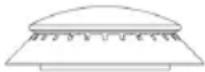 | |||||||||||
| Auxiliary (small) | 27 52 | 1,10 79 | 78 0,35 25 | 25 73 1,10 0,35 | |||||||
| Semi-rapid (medium) | 34 65 | 1,75 127 | 125 0,45 | 32 32 98 | 1,75 0,45 | ||||||
| Rapid (large) | 44 82 2,80 | 203 200 | 0,75 54 | 53 122 2 | 80 0,75 | ||||||
| Trible crown | 65 97 3,70 | 268 264 | 1,50 109 | 133 133 | 3,70 1,50 | ||||||
| Gas oven burners | |||||||||||
| 60L (60x50-60x60-70x50-70x60) - (sliding trolley 80x60-90x60) - (ventilato gas doppio forno 90x60) | 55 | 85 f/svasato | 3,30 2 | 40 236 1 | 10 80 79 | 130 f/svasato | 3,30 1 | 10 | |||
| Gian oven/giant gas oven ventilated/(...126Gv...) | 60 110 | 5,00 363 3 | 57 1,60 | 16 114 | 165 f/svasato | 5,00 1 | 60 | ||||
| Storage area (80x50 - 90x60) | 50 | 80 f/svasato | 2,60 1 | 89 186 1 | 10 80 79 | 115 f/svasato | 2,60 1 | 10 | |||
| Storage area and bottle cupboard (90x50 - 90x60) | 55 85 | 3,20 2 | 33 229 | 1,10 80 79 | 127 f/svatao | 3,20 1 | 10 | ||||
| Gas grill burners | |||||||||||
| 60L (60x50-60x60-70x50-70x60) - (sliding trolley 080x60-90x60) - double oven 90x60 | - | 77 | 2,30 | 166 | 164 | - | - | - | 115 | 2,30 | - |
| Giant Oven/giant oven ventilated (...126GVG...) | - | 90 | 3,30 | 240 | 236 | - | - | - | 140 | 3,30 | - |
| 60L (60x60 - 70x60) ventilated gas | - | 85 | 2,60 | 188 | 185 | - | - | - | 130 | 2,60 | - |
| GLASS PLATE AND ELECTRIC PLATE FEATURES TABLE 2 | |||||
| GIANT OVEN COOKER WITH GLASS PLATE: 800 + 800 W | |||||
| Corresponding positions of the knob and absorbed power | |||||
| Plate diameter in mm | Consumption knob position and W consumption | ||||
| 0 1 2 3 4 | |||||
| 80 0 90 180 | 200 450 | ||||
| 110 0 140 3 | 00 400 700 | ||||
| 145 0 187 2 | 50 750 1000 | ||||
| 180 0 300 6 | 00 900 1500 | ||||
| ABSORBED POWER BY THE ELECTRIC OVEN WITH THERMOSTAT TABLE 3 | ||||||
| MODELS | Base resistance | Sky resistance | Grill resistance | Maxi grill resistance | Circuit resistance | |
| Electric static model: 60x50-60x60-70x50-70x60 | 1650W 90 | 0W 1500W - - | ||||
| Mixed oven model: 70x50-70x60 1650W 900W 1500W - - | ||||||
| Multiple function model: MX 66 ASMF | 1650W 60 | 0W 1500W - - | ||||
| Multiple function model: 60x50-60x60-70x50-70x60 | 1650W 90 | 0W 1500W 21 | 0W 2000W | |||
| Radiant grill model: 60x60-70x60 1900W 700W 1800W 2500W 2000W | ||||||
| Radiant grill model: 90x60 1900W | 1000W | 2000W 2500W 2000W | ||||
| Multiple function giant oven | 1750W | 1000W | 2000W | 3000W | 2500W | |
| Double oven | Lt oven 60 Its | 1650W 90 | 0W 1500W 21 | 0W 2000W | ||
| Rh oven 30 Its | 1200W 50 | 0W 1000W - - | ||||
| Model with storage cupboard:80x50-80x60-90x50-90x60 | 1400W 70 | 0W 1200W - - | ||||
| Model with bottle: 90x50-90x60 | 1400W 70 | 0W 1200W - - | ||||
| Mod. : 60x60-70x50/60-90x50/60 | - | 1500W | - | - | - | |
| Giant gas oven | - | 1750W - | -- | |||
| Mod. gas with storage cupboard:80x50/60-90x50/60 | - | - | 1200W - - | |||
| Mod. Gas 90x60-80x60 with sliding trolley | - | - | 1500W - - | |||
| Electric model 90x60-80x60 with sliding trolley | 1650W 90 | 0W 1500W 21 | 0W 2000W | |||
| Giant oven gas ventilated model90x60 | - | - | 2000W - - | |||
| Giant oven ventilated gas model60x60-70x60 | - | - | 1800W - - | |||
| Oven 30Lts cooker ...D126... 1200W 500W 1000W - - | ||||||
| COOKER MODEL UP & DOWN TABLE 4 | |
| DIMENSIONS | |
| Height 900-915 mm | |
| Weight 600 mm | |
| Depth 600 mm (excluding the oven door handle) | |

| CHARACTERISTICS OF THE OVEN BURNERS | |||
| Burners Top oven Top grill | Bottom oven | ||
| Rated heating capacity kW | 1,70 2,70 2,40 | ||
| Minimum heating capacity kW | 0,80 - 1,00 | ||
| Injector | |||
| G20 20 mbar ∅ 1/100 mm | 95 125 110 | ||
| G30 30 mbar ∅ 1/100 mm | 62 80 72 | ||
| By-pass | |||
| G20 20 mbar ∅ 1/100 mm | Reg. - Reg. | ||
| G30 30 mbar ∅ 1/100 mm | 42 - 48 | ||
Oven UP temperature: min. 130°C - max 270°C
Oven DOWN temperature: min. 130°C - max 270°C
| OVEN ELECTRICAL FEATURES | |||
| OVEN UP |  | Base resistance | 1200W |
| Sky resistance 950W | |||
| Grill resistance | 1900W | ||
| OVEN DOWN |  | See table no.3 | |
LOFRA®
NUOVA LOFRA S.r.l.
Via Montegrotto, 125 - Torreglia (PADOVA) - ITALY
Tel.: +39 - 049 9904811
Fax: + 39 - 049 9904800
Web Site: www.lofra.it