
ZEN-4GS NAT - Cooker EDESA - Free user manual and instructions
Find the device manual for free ZEN-4GS NAT EDESA in PDF.


| Product Type | Freestanding Gas Cooker |
| Brand | Edesa |
| Model | ZEN-4GS NAT |
| Dimensions (W x D x H) | 50 cm x 50 cm x 85 cm |
| Energy Source | Natural Gas (G20/G25) / LPG (G30/G31) convertible |
| Hob Burners | Rapid (3.0 kW), Semi-rapid (1.65 kW), Auxiliary (1.0 kW) - 4 burners total |
| Oven Burner | Gas oven burner, 2.1 kW (NG) / 2.1 kW (LPG) |
| Grill Burner | Gas grill burner, 2.0 kW (NG) / 2.0 kW (LPG) |
| Oven Thermostat | Yes, adjustable temperature |
| Ignition | Manual (match or lighter) - no electric ignition |
| Flame Safety Device | Yes, on all burners (hob, oven, grill) |
| Oven Door | Removable for cleaning |
| Adjustable Feet | Yes, up to 30 mm height adjustment |
| Gas Connection | 1/2" BSP male thread, flexible hose (max 1.5 m) or rigid pipe |
| Ventilation Requirements | Room ventilation: 100 cm² fresh air opening; hood min. 65 cm above pan support |
| Oven Capacity | Approx. 60 L (estimated from dimensions) |
| Accessories Included | Wire grid, deep tray, grill heat shield |
| Cleaning | Enameled interior, stainless steel surfaces; removable door for easy cleaning |
| Safety Features | Child lock (not specified), flame failure device, heat shield for grill |
| Warranty | Standard manufacturer warranty (details not provided) |
| Country of Manufacture | Spain (Edesa based in Mondragón) |
Frequently Asked Questions - ZEN-4GS NAT EDESA
User questions about ZEN-4GS NAT EDESA
0 question about this device. Answer the ones you know or ask your own.
Ask a new question about this device
Download the instructions for your Cooker in PDF format for free! Find your manual ZEN-4GS NAT - EDESA and take your electronic device back in hand. On this page are published all the documents necessary for the use of your device. ZEN-4GS NAT by EDESA.
USER MANUAL ZEN-4GS NAT EDESA
natural_image
Silhouettes of multiple human figures in motion, no text or symbols visibleES
ZEN-4GS BUT ZEN-4GS NAT
natural_image
Illustration of a kitchen oven with six burners and a double-burned top, enclosed in a circular frame (no text or symbols)edesa
natural_image
Illustration of a cooking pan with four pots and scattered kitchen utensils (no text or symbols)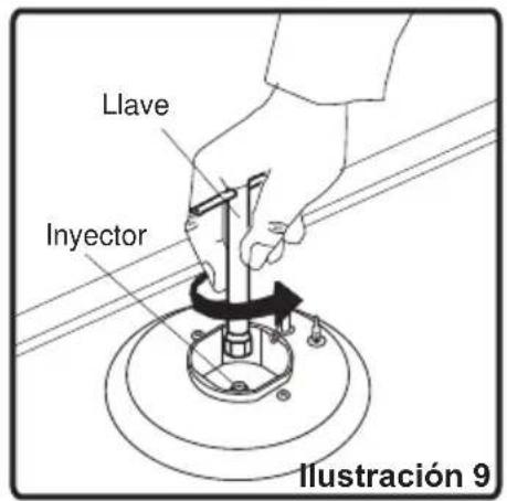
natural_image
Simple line drawing of a circular object with internal vertical divisions and a curved line, no text or symbols present.natural_image
Simple line drawing of a circular object with horizontal bands and a curved line, no text or symbols present.natural_image
Simple line drawing of a circular device with internal vertical lines and a curved arrow, no text or symbols present.natural_image
Simple circular diagram with diagonal lines and a curved arrow, no text or symbols presentnatural_image
Technical diagram showing a screw being inserted into a bracket, with an arrow indicating rotational motion (no text or symbols)natural_image
Illustration of a cooking pot with four panes and surrounding kitchen utensils (no text or symbols)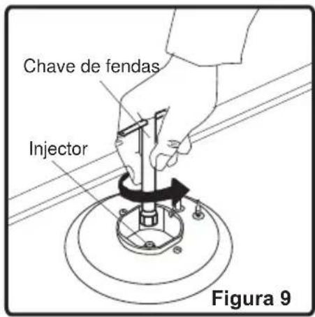
natural_image
Diagram showing a mechanical component with two circular features and dashed alignment lines, labeled 'Figura 11' (no text or symbols on the diagram itself)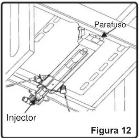
natural_image
Simple line drawing of a pot with crossed lines indicating heating or cooking process (no text or symbols)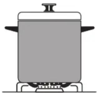
natural_image
Simple line drawing of a cooking pot on a stove (no text or symbols)Figura 17
natural_image
Technical line drawing of a battery pack assembly with two views (top and side), no text or symbols present.Acessórios do forno
Our goal is to offer you products with high quality that exceed your expectations. Your appliance is produced in modern facilities carefully and particularly tested for quality.
This manual is prepared in order to help you use your appliance that is manufactured by the most recent technology, with confidence and maximum efficiency.
Before using your appliance, carefully read this guide that includes the basic information for right and safe installation, maintenance and use. Please contact to the nearest Authorized Service for the installation of your product.
CE Declaration of conformity
This appliance has been designed to be used only for home cooking. Any other use (such as heating a room) is improper and dangerous.
This appliance has been designed, constructed, and marketed incompliance with:
• Safety requirements of the "Gas" Directive 2009/142/EC;
• Safety requirements of the "Low voltage" Directive 2006/95/EC;
• Safety requirements of the "EMC" Directive 2004/108/EC;
- Requirements of the Directive 93/68/EC.
CONTENTS:
- BRIEF PRESENTATION OF PRODUCT
- WARNINGS
- INSTALLATION AND PREPARATIONS FOR USE
3.1 Environment where the appliance to be installed
3.2 Installation of product
3.3 Adjustment of feet
3.4 Gas connection
3.5 Gas conversion
- USE OF YOUR PRODUCT
4.1 Use of gas burners
4.1.1 Control of hob burners
4.1.2 Control of oven burner
4.1.3 Control of grill burner
4.1.4 Use of digital minute minder
4.1.5 Use of mechanical minute minder
4.2 Accessories used in oven
- CLEANING AND MAINTENANCE
5.1 Cleaning
5.2 Maintenance
- SERVICE AND TRANSPORT
6.1 Basic troubleshooting before contacting service
6.2 Information related to the transport
1. BRIEF PRESENTATION OF PRODUCT
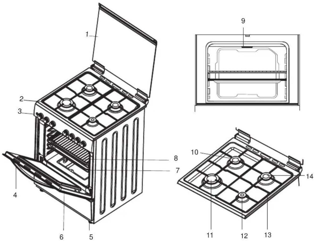
| MODEL | DEPTH (cm) | WIDTH (cm) | HEIGHT (cm) |
| ZEN-4GS BUT | 50 | 50 | 85 |
| ZEN-4GS NAT | 50 | 50 | 85 |
List of Components:
1- Lid
2- Cooktop
3- Control Panel
4- Oven Door Handle
5- Adjustable Feet
6- Oven Door
7- Oven Tray
8- Wire Grid
9- Grill Burner
10- Semi-Rapid Burner
11- Rapid Burner
12- Auxiliary Burner
13- Pan Support
14- Semi-Rapid Burner
2. WARNINGS
TAKE ALL IMPORTANT SAFETY MEASURES AND READ THE MANUAL COMPLETELY BEFORE USING THE APPLIANCE.
General Safety
- These warnings are provided in the interest of your safety. Read this manual carefully before using the appliance.
- This appliance has been designed for non-professional, domestic use only.
- This appliance is not intended for use by persons (including children) with reduced physical, sensory or mental capabilities, or lack of experience and knowledge, unless they have been given supervision or instruction concerning use of the appliance by a person responsible for their safety.
- Your appliance is produced in accordance with the local and international standards and regulations applicable.
- The maintenance and repair works must be made only by authorized service technicians. The installation and repair works without following proper knowledge may endanger you.
- Do not try to lift or move the appliance by pulling the door handle.
- It is dangerous to alter or modify the specifications of the appliance in any way.
Installation
- The appliance must be installed by an authorized technician and put into use. The producer is not responsible for any damage that might be caused by defective placement and installation by unauthorized people.
- When you unpack the appliance, make sure that it is not damaged during transportation. In case of any defect; do not use the appliance and contact to the authorized maintenance service immediately. As the materials used for package (nylon, stapler, strafoam...etc) may cause harmful effects to children, they should be collected and removed immediately.
For authorized people;
- Compare the features of the electricity network with the technical information on the rating label before plugging the appliance in.
- Prior to installation, ensure that the local distribution conditions (nature of the gas and gas pressure) and the adjustment of the appliance are compatible. The adjustment conditions for this appliance are stated on the label.
- This appliance is not connected to a combustion products evacuation device. It shall be installed and connected in accordance with current installation regulations. Particular attention shall be given to the relevant requirements regarding ventilation.
During Use
- When you first run your oven a certain smell will be emanated arising from the insulation materials and the heater elements. For this reason, before using your oven, run it empty at maximum temperature for 45 minutes. At the same time you need to properly ventilate the environment in which the product is installed.
- While your appliance operates, its outside surfaces heat up. The interior surfaces of oven and the flue outlet are quite hot. Even if the appliance is turned off, these parts keep its heat for a specific time. Do not touch onto hot surfaces and keep children away.
• Always use oven gloves to remove and replace food in the oven. - Always stand back from the appliance when opening the oven door to allow any build up of steam or heat to release.
- Do not leave the cooker while cooking with solid or liquid oils. They may catch fire on condition of extreme heating. Never pour water to the flames that are caused by oil. Cover the saucepan or frypan with its cover in order to choke the flame that has occurred in this case and turn the cooker off.
- CAUTION: The use of a gas cooking appliance results in the production of heat, moisture and products of combustion in the room in which it is installed. Ensure that the kitchen is well ventilated especially when the appliance is in use, keep natural ventilation holes open or install a mechanical ventilation device(mechanical extractor hood).
- CAUTION: This appliance is for cooking purposes only. It must not be used for other purposes, for example room heating.
- While using the grill burner, keep the oven door open and always use the grill deflector shield supplied with the product. Never use the grill burner with the oven door closed.
- If you will not use the appliance for a long time, plug it off. Keep the main control switch off. Also when you do not use the appliance, keep the gas valve off.
- Any spillage should be removed from the lid before opening.
- When the door of oven is open, do not leave anything on it. You may unbalance your appliance or break the cover.
- Protect your appliance against atmospheric effects. Do not leave it to effects such as sun, rain, snow, powder etc.
- Do not keep flammable materials close while the appliance is operating.
2. WARNINGS
- Pay attention to the cables of the other electrical devices operating near the appliance, so as not to touch to hot points.
- The appliance is not intended to be operated by means of an external timer or separate remote control system.
- Do not hang towels, dishcloths or clothes from the appliance or its handles.
- This manual is prepared for more than one model in common. Your appliance may not have some of the features that is explained in manual. Pay attention to the expressions that have figures, while you are reading the operating manual.
Safety when Cleaning and Maintenance
- Turn the appliance off before the operations such as cleaning or maintenance. You can do it after plugging the appliance off or turning the main switches off.
- Do not use harsh abrasive cleaners or sharp metal scrapers to clean the oven door glass since they can scratch the surface, which may result in shattering of the glass.
- Every care is taken to ensure the safety of the customer. Glass can break, be careful when cleaning the glass as not to scratch it. Do not knock or hit the glass with the accessories.
Children Safety
- CAUTION: Accesible parts may be hot when the grill is in use. Young children should be kept away. Keep children away from the oven.
- While the front door is open, do not let climb on the door or sit on it.
• Children should be supervised to ensure that they do not play with the appliance.
FOR EFFICIENCY AND SAFETY OF APPLIANCE, WE RECOMMEND YOU ALWAYS TO USE THE ORIGINAL SPARE PARTS AND TO CALL ONLY OUR AUTHORIZED SERVICES IN CASE OF NEED.
3. INSTALLATION AND PREPARATIONS FOR USE
This modern, functional and practical cooker, that was manufactured with the parts and materials of highest quality, will meet your cooking needs in every aspect. You must surely read this manual so that you don't have any problem in future and to be able to have satisfactory results. The following information are the required rules for right installation and service processes. It must be read especially by the technician who will install the appliance.

Contact to Authorized Service for installation of your product
3.1 Environment where your appliance will be installed
- Your product must be set up and used in a place where it will always have ventilation
• While hoie patinly timi su appliance needs 3 - There must be a natural ventilation enough to provide the gas to be used in the environment. The average air flow must directly come in through the air holes that will be opened on the walls that are opened towards outside.
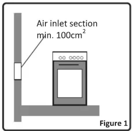
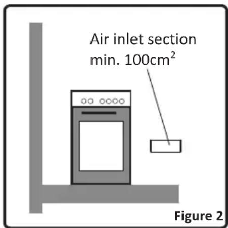
- These air holes must have at least the effective cross section of 100cm^2 for fresh air circulation (One or more air holes can be opened.). This hole (or holes) must be opened so that they are not blocked. Preferably they must be placed close to the bottom and at opposite side of the smokes of the burned gases that were emptied. If it seems not possible to open these ventilations in the place where the appliance is set up, the needed air can also be obtained through the next room, provided that this place is not a bedroom or a dangerous place. In this case this “next room” must also be ventilated as required.
Emptying of the Burned Gases from Environment
The cooking appliances that operate with gas, throw the burned gas wastes out directly to the outside or through the cooker hoods that are connected to the a chimney that opens directly to the outside. If it seems that it is not possible to install a cooker hood, it is required to set an electric fan on the window or wall that has access to fresh air. This electric fan must have the capacity to change the air of the kitchen environment 4-5 times of its own volume of air per hour.
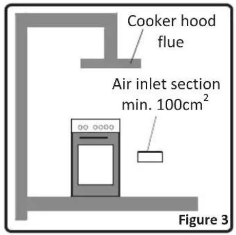
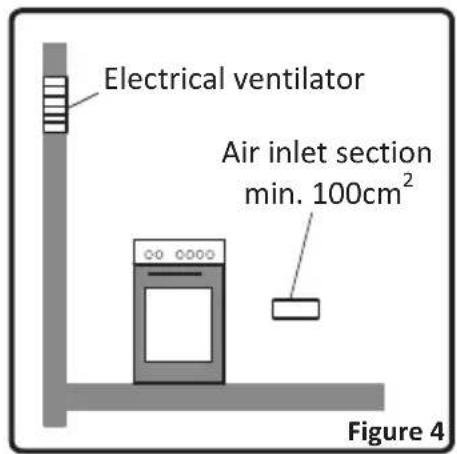
3.2 Installation of product
There are some factors that must be paid attention to while installing your product. Surely be very careful to while installing your product. Pay attention to our below instructions in order to be able to prevent any problems and/or dangerous situations that may occur later.
- The appliance can be placed close to other furniture on condition that in the area where the oven is set up, the furniture's height does not exceed the height of the cooker panel.
- Pay attention not to place it near the refrigerator, there must be no flammable or inflammable materials such as curtain, waterproof cloth, etc. that will begin to burn quickly.
- It is required that there must be least a 2cm blank space around the product for air circulation
- The furniture close to product must be manufactured resistant to temperatures up to
- If the kitchen furniture are higher than the cooktop, it must be at least 10cm away from the cooker's side.
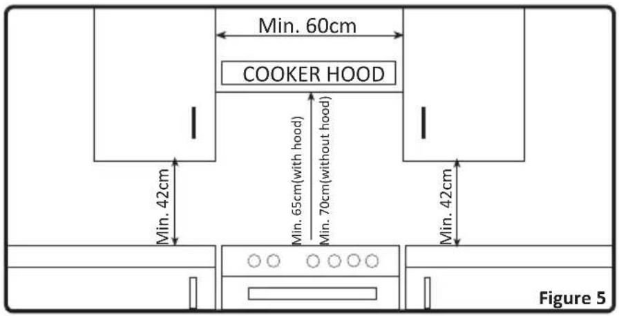
The minimum heights from the pan support and wall cupboards to cooker hoods with fan over the product, are shown in figure 5. Thus, the cooker hood must be at minimum 65cm height from the pan support. If there is no cooker hood, this height must not be less than 70cm.
3. INSTALLATION AND PREPARATIONS FOR USE
3.3 Adjustment of feet
natural_image
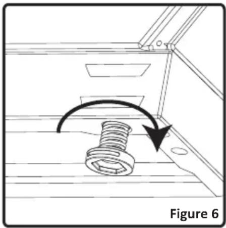
Technical diagram showing a screw being inserted into a bracket, with an arrow indicating rotational motion (no text or symbols)Your products product adjustable feet. When the is placed where to be used, check if the product is balanced. If it is not balanced, you can make the adjustment by turning the feet clockwise if required. It is possible to raise the appliance maximum 30mm by the feet. If the feet are adjusted appropriately, it is required not to move the appliance by dragging, it should be moved by lifting it up.
3.4 Gas connection
Assembly of gas supply and leakage check
The connection of the appliance should be performed in accordance with local and international standards and regulations applicable. You can find the information related to appropriate gas types and appropriate gas injectors on technical data table. If the pressure of used gas is different than these values stated or not stable in your area, it may be required to assemble an available pressure regulator on the gas inlet. It is certainly required to contact to the authorized service to make these adjustments.
The points that must be checked during flexible hose assembly
If the gas connection is made by a flexible hose that is fixed on the gas inlet of appliance, it must be fixed by a pipe collar as well. Connect your appliance with a short and durable hose that is as close as possible to the gas source. The hose's permitted maximum lenght is 1.5m. The hose that brings gas to the appliance must be changed once a year for your safety.
The hose must be kept clear from areas that may heat up to temperatures in excess of 50^ C. The hose must not be ruptured, bent or folded. It must be kept clear of sharp corners, moving things, and should not be defective. Before assembly, it must be checked whether there is any production defect.
As gas is turned on, all connection parts and hose must be checked with soapy water or leakage fluids. Do not use naked flame to check gas leakage. All metal components used during gas connection must be clear of rust. Also check the expiry dates of components to be used.
The points that must be checked during fixed gas connection assembly
To assemble a fixed gas connection (gas connection made by threads, e.g. a nut), there are different methods used in different countries. The most common parts are already supplied with your appliance. Any other part can be supplied as spare part.
During connections always keep the nut on the gas manifold fixed, while rotating the counter-part. Use spanners of appropriate size for safe connection. For all surfaces between different components,
3. INSTALLATION AND PREPARATIONS FOR USE
always use the seals provided in the gas conversion kit. The seals used during connection should also be approved to be used in gas connections. Do not use plumbing seals for gas connections.
Remember that this appliance is ready to be connected to gas supply in the country for which it has been produced. The main country of destination is marked on the rear cover of the appliance. If you need to use it in another country, any of the connections in the figure below can be required. In such a case, learn the appropriate connection parts and obtain those parts to perform a safe connection.
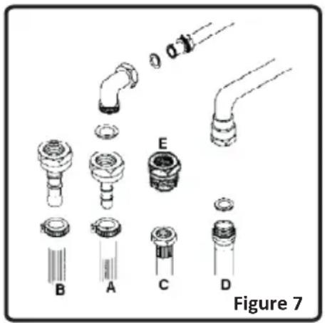
It is required to call the authorized service to be able to make the gas connections appropriately and in compliance with safety standards.

Surely do not use any match or lighter for control of gas leakage ATTENTION! .
3.5 Gas conversion
Caution : The following procedures must be undertaken by authorized service people.
Your appliance is adjusted to be operated with LPG/NG gas. The gas burners can be adapted to different types of gas, by replacing the corresponding injectors and adjusting minimum flame length suitable to the gas in use. For this purpose, following steps should be performed:
Changing injectors:
Hob Burners:
- Cut off the main gas supply and unplug from the electric mains
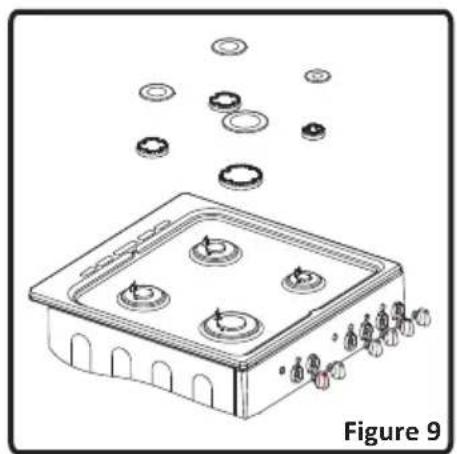
- Remove the burner cap and the adapter(Figure 9).
- Unscrew the injectors. For this, use a 7mm spanner(Figure 10).
- Replace the injector with the ones from the gas conversion kit, with corresponding diameters suitable to the type of gas that is going to be used, according to the information chart (which is also supplied in the gas conversion kit).
natural_image
Illustration of a gas stove with four fans and surrounding circular components, labeled Figure 9 (no text or symbols on the main diagram)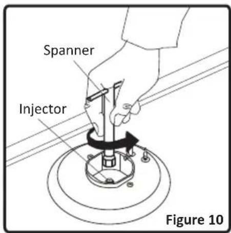
Oven/Grill Injectors:
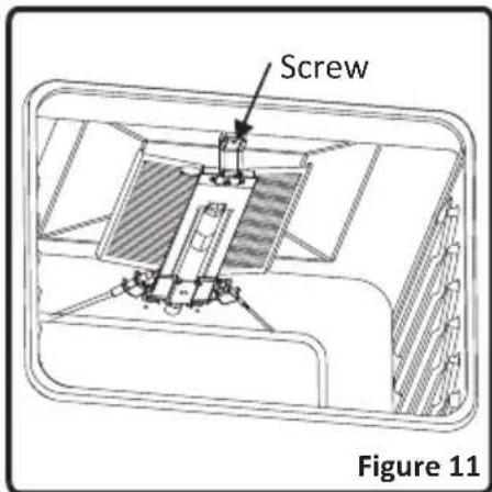
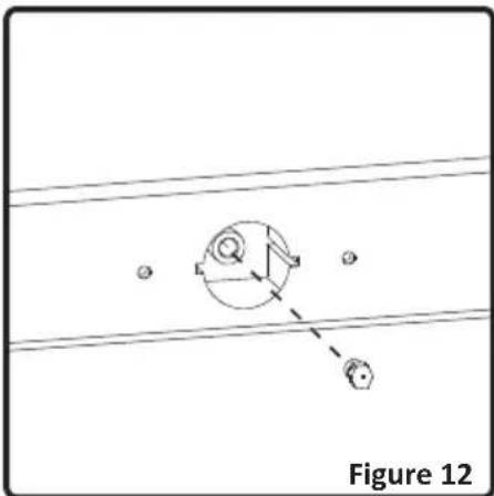
The oven and grill injectors are assembled by a single screw that is placed on the tip of the burner. For grill burners, this screw is already visible(Figure 11). Remove the screw, pull the grill burner to yourself and you will see the injector revealed on the rear surface of the oven cavity (Figure 12).
For oven burners, open the drawer compartment and you will see the assembly screw below the burner (Figure 13). Remove the screw, move the burner diagonally and the injector will be revealed on the rear side of the burner box (Figure 12).
Remove the injectors with a 7mm spanner and replace the injector with the ones from the spare set, with corresponding diameters suitable to the type of gas that is going to be used, according to the information chart (which is also supplied in the gas conversion kit).
natural_image
Technical diagram showing a mechanical component with two circular features and alignment lines, labeled Figure 12 (no text or symbols on the diagram itself)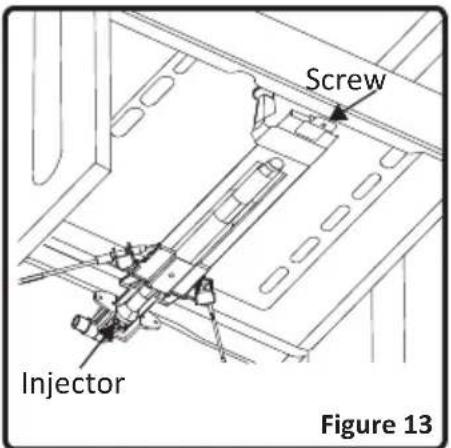
Adjusting the reduced flame position:
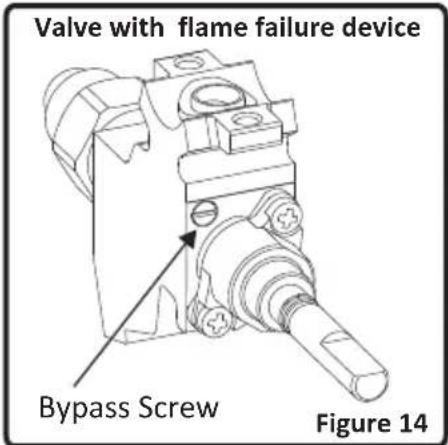
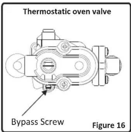
The flame length in the minimum position is adjusted with a flat screw located on the valve. For valves with flame failure device, the screw is located on the side of the valve spindle(Figure 14). For easier reduced flame adjustment, it is advised to remove the control panel (and microswitch, if present) during adjustment.
3. INSTALLATION AND PREPARATIONS FOR USE
To determine the minimum position, ignite the burners and leave them on in minimum position. Remove the with the help of a small screwdriver fasten or loosen the bypass screw around 90 angular degrees. When the flame has a length of at least 4 ~mm , the gas is well distributed. Make sure that the flame does not die out when passing from the maximum position to the minimum position. Create an artificial wind with your hand toward the flame to see if the flames are stable.
For oven burner, operate the oven burner at minimum position for 5 minutes, then open and close the oven door for 2-3 times to check the flame stability of the burner.
Reduced flame position adjustment is not required for grill burners.
The position the bypass screw must be loosened for conversion from LPG to NG. For conversion from NG to LPG, the same screw must be fastened. Make sure that the appliance is unplugged from the electric mains and the gas supply is open.
Changing the gas inlet:
For some countries, the gas inlet type can be different for NG/LPG gases. In such a case, remove the current connection components and nuts (if any) and connect the new gas supply accordingly. In all conditions, all components used in gas connections should be approved by local and/or international authorities. In all gas connections, refer to the “Assembly of gas supply and leakage check” clause explained before.
4. USE OF YOUR PRODUCT
4.1 Use of gas burners
Ignition of the burners
To determine which knob controls which burner, check the position symbol above the knob.
• Manual Ignition of the Gas Burners
If your appliance is not equipped with any ignition aid or in case there is a failure in the electric network, follow the procedures listed below:
For Hob Burners: To ignite one of the burners, press and turn its knob counter-clockwise so that the knob is in maximum position, approach a match, taper or another manual aid to its upper circumference. Move the ignition source away as soon as you see a stable flame.
For Oven Burner: To ignite the oven burner, press and turn the oven control knob counter-clockwise so that the knob is in maximum position, approach a match, taper or another manual aid to the ignition hole that is located on the front left corner of the burner. Move the ignition source away as soon as you see a stable flame.
For Grill Burner: To ignite the grill burner, turn the grill valve in the clockwise position until the marker on the knob points at the grill sign. Then, keep the knob pressed and approach a match, taper or another manual aid to the holes that are situated on the burner. Move the ignition source away as soon as you see a stable flame.
Flame safety device:
Hob Burners
Hobs equipped with flame failure device provide security in case of accidentally extinguished flame. If such a case occurs, the device will block the burners gas lines and will avoid any accumulation of unburned gas. Wait 90 seconds before re-igniting an extinguished gas burner.
Oven / Grill Burners
Regardless of the model of your appliance, all oven burners are equipped with a gas safety device. For this reason, during ignition, keep the oven knob pressed until you see stable flames. If the flames are cut out after you release the knob, repeat the procedure again. If the oven burner does not ignite after you keep the burner knob pressed for 30 seconds, open the oven door and do not attempt re-ignition for at least 90 seconds. When oven flames go out accidentally, repeat the same procedure.
4.1.1 Control of the hob burners
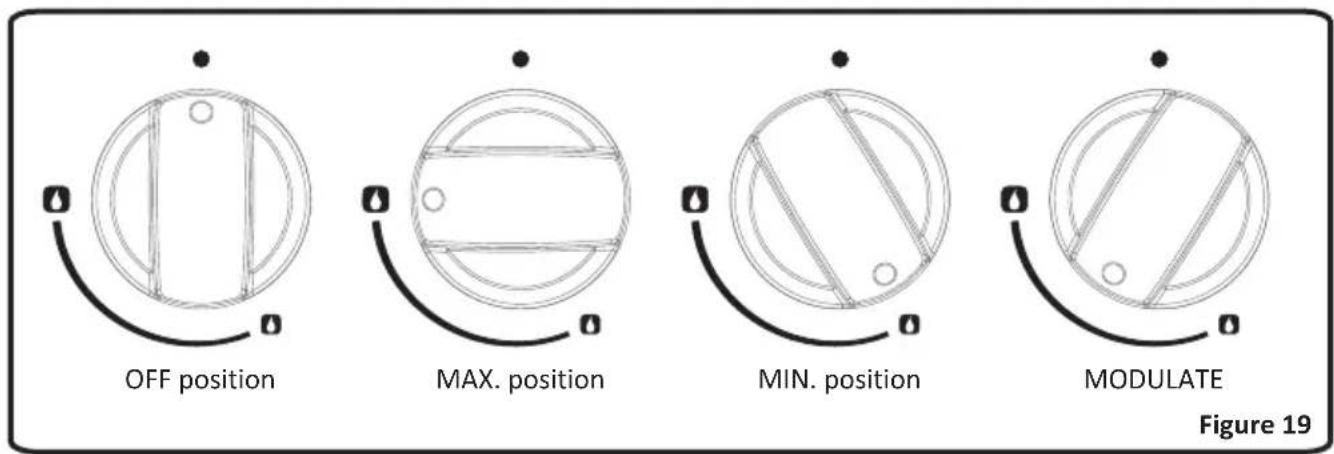
The knob has 3 positions: Off (0), maximum (big flame symbol) and minimum (small flame symbol). After you ignite the burner in maximum position; you can adjust the flame length between maximum and min. positions. Do not operate the burners when the knob position is between maximum and off positions.
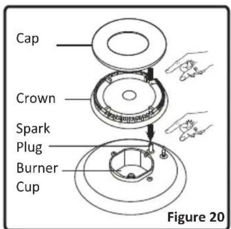
After the ignition, check the flames visually. If you see yellow tip, lifted or unstable flames; turn the gas flow off, and check the assembly of burner caps and crowns (Figure 20). Also, make sure that no liquid has flown into the burner cups. If the burner flame goes out accidentally, turn the burner off, ventilate the kitchen with fresh air, and do not attempt re-ignition for 90 sec.
When turning the hob off, turn the knob in the clockwise direction so that the knob shows "0" position or the marker on the knob points upwards.
4. USE OF YOUR PRODUCT
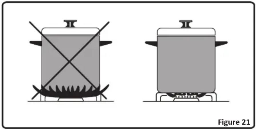
Your hob has burners of different diameters. The most economic way of using gas is to choose the correct size gas burners for your cooking pan size and to bring the flame to minimum position once the boiling point is reached. It is recommended to always cover your cooking pan.
In order to obtain maximum performance from the main burners, use pots with the following flat bottom diameters. Using smaller pots than the minimum dimensions stated below will cause energy loss.
Rapid Burner: 22-26cm
Semi-rapid Burner: 14-22cm
Auxiliary Burner: 12-18cm
natural_image
Two identical cooking pots with crossed handles on their bases, placed side by side (no text or symbols)When the burners are not in use for prolonged periods, always turn the main gas control valve off

WARNING:
- Use only flat pans and with a sufficiently thick base.
- Ensure that the base of the pan is dry before placing it on the burners.
- The temperature of accessible parts may be high when the appliance is operating. So it is imperative to keep children and animals out of the reach of the burners during and after cooking.
- After use, the hob remains very hot for a prolonged period of time, do not touch it and do not place any object on top of the hob.
- Never place knives, forks, spoons and lids on the hob as they will get hot and could cause serious burns.
4.1.2 Control of the Oven Burner
After you ignite the oven burner as explained before, you can adjust the temperature inside the oven as you require, using the numbers on the control panel or knob ring: Bigger numbers mean higher temperatures, while smaller numbers mean lower temperatures. If your oven is equipped with an oven thermostat; refer to the temperature table below for the temperature references of those numbers. Do not operate the appliance between "Off" position and first temperature marker
4. USE OF YOUR PRODUCT
in the counter-clockwise direction. Always use the oven between maximum and minimum numbers. When turning the oven off, turn the knob in the clockwise direction so that the knob shows "0" position.
Preheating
When you need to preheat the oven, we recommend you do so for 10 minutes. For recipes needing high temperatures, e.g. bread, pastries, scones, soufflés etc., best results are achieved if the oven is preheated first. For best results when cooking frozen or cooked chilled ready meals always preheat the oven first.
Cooking
- Ensure that food is placed centrally on the shelf and there is sufficient room around the baking tray/dish to allow for maximum circulation.
- Stand dishes on a suitably sized baking tray on the shelf to prevent spillage onto the oven base and to help reduce cleaning.
- The material and finish of the baking tray and dishes used affect base browning. Enamel ware, dark, heavy or non-stick utensils increase base browning. Shiny aluminum or polished steel trays reflect the heat away and give less base browning.
- When cooking more than one dish in the oven, place dishes centrally on different shelves rather than cluster several dishes on one shelf, this will allow the heat to circulate freely for the best cooking results.
- If you are cooking more than one tray of similar items, for example cakes or biscuits, swap the trays during cooking or you can remove the top tray when the food is cooked and move the lower tray to the higher shelf to finish cooking.
- Do not place baking trays directly on the oven base as it interferes with the oven air circulation and can lead to base burning; use the lower shelf position.
4.1.3 Control of the grill burner
CAUTION: Accessible parts may be hot when the grill is in use. Young children should be kept away.
Right after you ignite the burner, place the grill heat shield under the control panel. After that, lift the oven door up slowly until it stops at the semi-open (30°) position and touches the heat shield.
Assembling the grill heat shield
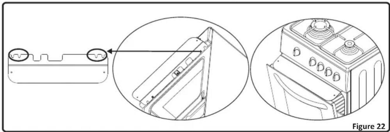
Hold the heat shield as the warnings face upwards. There are two small slots on the right and left side of the rear edge of the shield, as shown in the below figure.
natural_image
Technical line drawing of a mechanical component with two views: top shows a side view and bottom shows the exterior view (no text or symbols)There are two screw equipped with bushes under the oven control panel. Align the bushes with the assembly slots so that the shield is stuck between the control panel and the bush. Push the shield towards the appliance until it is firmly in its place.
Cooking
- The grill burner cannot be modulated between maximum and minimum positions and creates a source of heat at a constant rating. When turning the grill burner off, turn the knob in the clockwise direction so that the knob shows "0" position.
- Place the tray on the shelf below the grid in order to collect the fat during grilling.
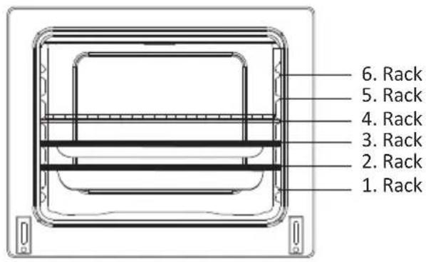
- Place the wire grid on the topmost shelves; 5^th or 6 ; provided that the food does not touch the grill burner.
- Preheat the grill on a full setting for a few minutes before sealing steaks or toasting. The food should be turned over during cooking as required.
- Food should be thoroughly dried before grilling to minimize splashing. Brush lean meats and fish lightly with a little oil or melted butter to keep them moist during cooking.
- Foods should be placed on the center of the grid to allow maximum circulation of air.
- Never cover the grill pan or grid with foil as this can lead to grill fires.
- If your appliance has a grill pan and handle set as an accessory, refer to accessories section for its usage.

WARNING: Ensure that the grill is turned off before closing the door.
4.2 Accessories used in oven
- The product already supplied with accessories. You can also use accessories you purchase from the market, but they must be heat and flame resistant. You can also use glass dishes, cake molds, special oven trays that are appropriate for use in oven. Pay attention to the using instructions by the manufacturer of those accessories.
- In case small size dishes are used, place the dish onto the wire grid, as it will completely be on the middle part of the grid.
- If the food to be cooked does not cover the oven tray completely, if the food is taken from the deep freezer or the tray is being used for collection of food's juices that flow during grilling, the form changes can be observed in the tray because of the high heat that occur during cooking or roasting. The tray will return to its old form only when the tray cool down after cooking. This is a normal physical event that occurs during heat transfer.
- Do not leave glass tray or dish in cold environment right away after cooking in glass tray or dish. Do not put onto cold and wet surfaces. Place on a dry kitchen cloth or dish cross, ensure it to cool slowly. Otherwise the glass tray or dish may be broken.
- If you will grill in your oven; we recommend you to use the grid that was given in tray together with product (If your product includes this material). If you will use the big wire grid; put a tray onto one of the lower shelves for fat to be collected. Also put some water into it for ease of cleaning.
- As explained in the corresponding clauses, never attempt to use the gas operated grill burner without the grill protection lid. If your oven has a gas operated grill burner, but the grill heat shield is missing, or if it is damaged and cannot be used, request a spare part from the nearest service.
Oven Cavity
Rack positions for molded racks
Oven Accessories
* The accessories of your oven may be different due to the model of your product.
| Wire grid | |
| Wire grid is used to grill or to place different cookwares on it.To locate the wire grid correctly in the cavity, put it to any rack and push it up to the end. | |
| Deep Tray | |
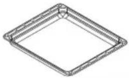 | Deep tray is used to cook stews.To locate the tray correctly in the cavity, put it to any rack and push it up to the end. |
5. CLEANING AND MAINTENANCE
5.1 Cleaning
Be sure that all control switches are off and your appliance cooled before cleaning your oven. Plug off the appliance. Check whether they are appropriate and recommended by the manufacturer before using the cleaning materials on your oven. As they may damage the surfaces, do not use caustic creams, abrasive cleaning powders, thick wire wool or hard tools. In case the liquids that overflow around your oven burn, the enameled parts may be damaged. Immediately clean the overflown liquids.
Cleaning of oven
The inside of enameled oven is cleaned in the best way when the oven is warm. Wipe the oven with a soft cloth that had been soaked in soapy water after each use. Later wipe it with a wet cloth once more and then dry it. It may be required to use a liquid cleaning material from time to time and make a complete cleaning. Do not clean with dry/powder cleaners or steam cleaners.
Removal of oven door
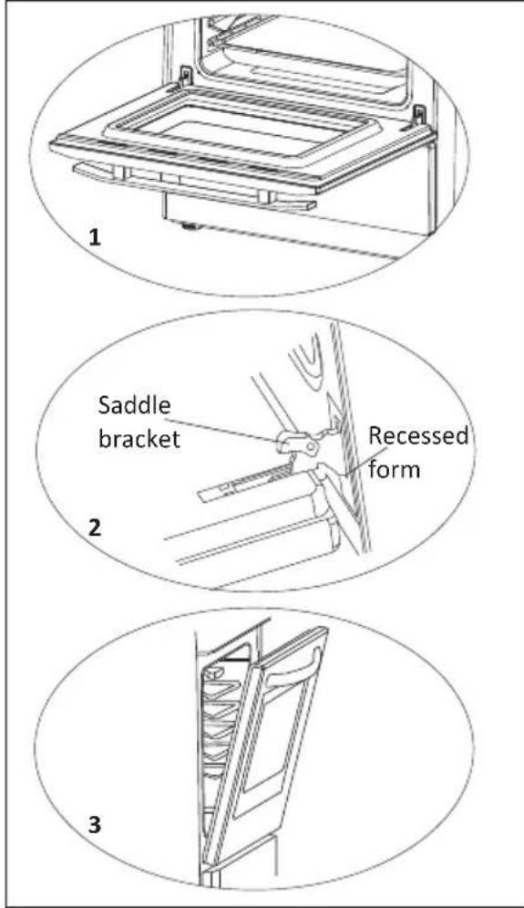
To remove the oven door;
- Open the oven door(1).
- Open the saddle bracket up to end position(2).
- Close the door till it almost reaches to the full closed position as shown in 3 ^rd figure and remove the door by pulling it towards yourself.
NOTE: To re-assemble the door follow the opposite rules of removal.
⚠️ Please pay attention that the recessed forms should be positioned properly on the hinge counterparts as shown on 2 ^nd figure.
Cleaning of Gas Cooker - Hob Part
- Lift up the pan supports, caps and crowns of hob burners(Figure 16).
- Wipe and clean the back panel with a soapy cloth.
- Wash the caps and crowns of hob burners and rinse them. Do not leave them wet, immediately dry them with paper cloth.
• After cleaning, make sure that you re-assemble the parts correctly. - Do not clean any part of the hob with metal sponge. It causes the surface be scratched.
- The pan support top surfaces may be scratched in time due to usage. These parts will not get rusted and it is not a production fault.
- During cleaning of the hob plate, make sure that no water flows inside the burner cups, as this may block the injectors.
Burner Caps:
Periodically, enameled pan support, enameled covers, burner heads must be washed with soapy warm water rinsed and dried. After drying them thoroughly, replace them correctly.
Enamelled Parts:
In order to keep them a new, it is necessary to clean them frequently with mild warm soapy water and then dry with cloth. Do not wash them while hot and never use abrasive powders or abrasive cleaning materials. Do not leave vinegar, coffee, milk, salt, water, lemon, or tomato juice to remain in contact with enameled parts for long periods of time.
Stainless Steel:
Stainless steel parts must be cleaned frequently with mildly warm soapy water and a soft sponge and then dry with a soft cloth. Do not use abrasive powders or abrasive cleaning metarials. Do not leave vinegar, coffee, milk, salt, water, lemon or tomato juice to remain in contact with stainless steel parts long periods of time.
5.2 Maintenance
Other Controls
Periodically check the gas connection pipe. Even if any simple abnormality is felt, inform the technical service to have it changed. We recommend the gas connection parts to be changed once a year. If any abnormality is felt while operating the control knobs of cooker, contact to the authorized service.
6. SERVICE AND TRANSPORT
6.1 Basic troubleshooting before contacting service
If the oven does not operate :
• The oven may be plugged off, there has been a black out.
If the oven does not heat :
- The heat may be not adjusted with oven's heater control switch.
Cooking (If lower-upper part does not cook equally):
- Check the shelf locations, cooking period and heat values according to the manual.
The hob burners do not operate correctly :
- Check if the burner parts are correctly assembled(especially after cleaning).
- The gas supply pressure may be too low/high. For appliances working with bottled LPG, the LPG cylinder may be depleted.
Except these, if you still have any problem with your product, please call to the Authorized Service.
6.2 Information related to transport
If you need any transport; keep the original case of product and carry it with its original case when needed to be carried. Follow the transport signs on packaging. Tape the cooker on upper parts, caps and crowns and pan supports to the cooking panels. Place a paper between the upper cover and cooking panel, cover the upper cover, then tape it to the side surfaces of oven. Tape cardboard or paper onto the front cover on interior glass of oven as it will be suitable to the trays, for the wire grid in your oven not to damage to the oven door during transport. Also tape the oven door to the side panels.
If you do not have the original packaging; prepeare a carriage box so that the appliance, especially external surfaces (glass and painted surfaces) of oven is protected against external threats.
INJECTOR TABLE
| II2H3+ES Clase-Classe:1 | LPG | NG | |||
| G30 | G31 | G20 | G25 | G20 | |
| 28-30 mbar | 28-30/37 mbar | 20 mbar | 25 mbar | 13 mbar | |
| RAPID BURNER | |||||
| Injector Diameter (%mm) | 87 | 87 | 129 | 132 | 150 |
| Nominal Rating (kW) | 3 | 3 | 3 | 2.75 | 3 |
| Consumption in 1h | 218.1 gr/h | 214.2 gr/h | |||
| Consumption in 1h(at 15°C and 1013mbar pressure) | 285.7 lt/h | 304.5 lt/h | 285.7 lt/h | ||
| SEMI-RAPID BURNER | |||||
| Injector Diameter (%mm) | 65 | 65 | 97 | 100 | 110 |
| Nominal Rating (kW) | 1.65 | 1.65 | 1.65 | 1.65 | 1.65 |
| Consumption in 1h | 120 gr/h | 117.9 gr/h | |||
| Consumption in 1h(at 15°C and 1013mbar pressure) | 157.1 lt/h | 182.7 lt/h | 157.1 lt/h | ||
| AUXILLARY BURNER | |||||
| Injector Diameter (%mm) | 50 | 50 | 77 | 80 | 90 |
| Nominal Rating (kW) | 1 | 1 | 1 | 1 | 1 |
| Consumption in 1h | 72.7 gr/h | 71.4 gr/h | |||
| Consumption in 1h(at 15°C and 1013mbar pressure) | 95.2 lt/h | 110.7 lt/h | 195.2 lt/h | ||
| OVEN BURNER | |||||
| Injector Diameter (%mm) | 68 | 68 | 100 | 105 | 115 |
| Nominal Rating (kW) | 2.1 | 2.1 | 2.1 | 2.1 | 1.9 |
| Consumption in 1h | 152.6 gr/h | 150 gr/h | |||
| Consumption in 1h(at 15°C and 1013mbar pressure) | 200 lt/h | 232.5 lt/h | 180.9 lt/h | ||
| GRILL BURNER | |||||
| Injector Diameter (%mm) | 70 | 70 | 107 | 105 | 115 |
| Nominal Rating (kW) | 2 | 2 | 2 | 2 | 1.8 |
| Consumption in 1h | 145.4 gr/h | 142.9 gr/h | |||
| Consumption in 1h(at 15°C and 1013mbar pressure) | 190.5 lt/h | 221.5 lt/h | 171 lt/h | ||
The symbol on the product or on its packaging indicates that this product may not be treated as household waste. Instead it shall be handed over to the applicable collection point for the recycling of electrical and electronic equipment. By ensuring this product is disposed of correctly, you will help prevent potential negative consequences for the environment and human health, which could otherwise be caused by inappropriate waste handling of this product. For more detailed information about recycling of this product, please contact your local city office, your household waste disposal service or the shop where you purchased the product.

natural_image
Silhouettes of a group of people in dynamic poses, no text or symbols visibleedesa
EDESA
Apdo. 49 B° San Andrés 18
20500 Mondragón (SPAIN)
info@edesa.com
www.edesa.com
- edesa
- Acessórios do forno
- CE Declaration of conformity
- CONTENTS:
- BRIEF PRESENTATION OF PRODUCT
- List of Components:
- WARNINGS
- TAKE ALL IMPORTANT SAFETY MEASURES AND READ THE MANUAL COMPLETELY BEFORE USING THE APPLIANCE.
- General Safety
- Installation
- For authorized people;
- During Use
- Safety when Cleaning and Maintenance
- Children Safety
- INSTALLATION AND PREPARATIONS FOR USE
- Contact to Authorized Service for installation of your product
- Environment where your appliance will be installed
- Emptying of the Burned Gases from Environment
- Installation of product
- Adjustment of feet
- Gas connection
- Assembly of gas supply and leakage check
- The points that must be checked during flexible hose assembly
- The points that must be checked during fixed gas connection assembly
- Gas conversion
- Changing injectors:
- Hob Burners:
- Oven/Grill Injectors:
- Adjusting the reduced flame position:
- Changing the gas inlet:
- USE OF YOUR PRODUCT
- Use of gas burners
- Ignition of the burners
- • Manual Ignition of the Gas Burners
- Flame safety device:
- Hob Burners
- Oven / Grill Burners
- Control of the hob burners
- WARNING:
- Control of the Oven Burner
- Preheating
- Cooking
- Control of the grill burner
- Assembling the grill heat shield
- Accessories used in oven
- Oven Cavity
- Oven Accessories
- CLEANING AND MAINTENANCE
- Cleaning
- Cleaning of oven
- Cleaning of Gas Cooker - Hob Part
- Burner Caps:
- Enamelled Parts:
- Stainless Steel:
- Maintenance
- Other Controls
- SERVICE AND TRANSPORT
- Basic troubleshooting before contacting service
- If the oven does not operate :
- If the oven does not heat :
- Cooking (If lower-upper part does not cook equally):
- The hob burners do not operate correctly :
- Information related to transport
Brand : EDESA
Model : ZEN-4GS NAT
Category : Cooker