
HG62IX - Cooker NORDMENDE - Free user manual and instructions
Find the device manual for free HG62IX NORDMENDE in PDF.


User questions about HG62IX NORDMENDE
0 question about this device. Answer the ones you know or ask your own.
Ask a new question about this device
Download the instructions for your Cooker in PDF format for free! Find your manual HG62IX - NORDMENDE and take your electronic device back in hand. On this page are published all the documents necessary for the use of your device. HG62IX by NORDMENDE.
USER MANUAL HG62IX NORDMENDE
natural_image
Front view of a four-gas stove with four panes and control knobs (no visible text or symbols)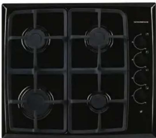
natural_image
Front view of a black gas stove with four vented grilles and control knobs (no visible text or symbols)Dear Customer,
Our goal is to offer you products with high quality that exceed your expectations. Your appliance is produced in modern facilities carefully and particularly tested for quality.
This manual is prepared in order to help you use your appliance that is manufactured by the most recent technology, with confidence and maximum efficiency.
Before using your appliance, carefully read this guide that includes the basic information for right and safe installation, maintenance and use. Please contact to the nearest Authorized Service for the installation of your product.
CE Declaration of conformity
This appliance has been designed to be used only for home cooking. Any other use (such as heating a room) is improper and dangerous.
This appliance has been designed, constructed, and marketed incompliance with:
• Safety requirements of the "Gas" Directive 2009/142/EC;
- Safety requirements of the "Low voltage" Directive 2006/95/EC;
• Safety requirements of the "EMC" Directive 2004/108/EC;
- Requirements of the Directive 93/68/EC.
CONTENTS:
- BRIEF PRESENTATION OF PRODUCT
-
WARNINGS
-
INSTALLATION AND PREPARATIONS FOR USE
3.1 Installation of product
3.2 Gas connection
3.3 Electric connection and safety
3.4 Gas conversion
- USE OF YOUR PRODUCT
4.1 Use of gas burners
4.2 Use of hotplate
4.3 Accesorries
- CLEANING AND MAINTENANCE
5.1 Cleaning
5.2 Maintenance
- SERVICE AND TRANSPORT
6.1 Basic troubleshooting before contacting service
6.2 Information related to the transport
1. BRIEF PRESENTATION OF PRODUCT
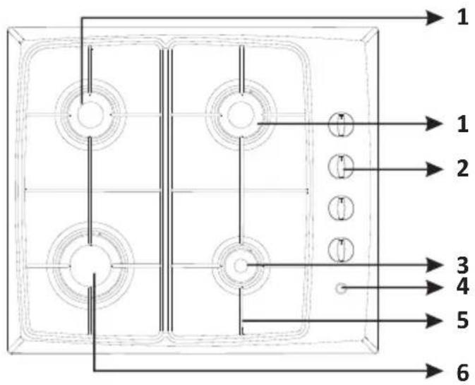
Gas Hob:
text_image
1 1 2 3 4 5 6List of Components:
1- Semi-Rapid Burner
2- Control Knobs
3- Auxiliary Burner
4- Electrical Ignition Button
5- Pan Support
6- Rapid Burner
* The appearance of your hob may be different than the model shown above due to its configuration.
2. WARNINGS
TAKE ALL IMPORTANT SAFETY MEASURES AND READ THE MANUAL COMPLETELY BEFORE USING THE APPLIANCE.
General Safety
- These warnings are provided in the interest of your safety. Read this manual carefully before using the appliance.
- This appliance has been designed for non-professional, domestic use only.
- This appliance is not intended for use by persons (including children) with reduced physical, sensory or mental capabilities, or lack of experience and knowledge, unless they have been given supervision or instruction concerning use of the appliance by a person responsible for their safety.
- Your appliance is produced in accordance with the local and international standards and regulations applicable.
- The maintenance and repair works must be made only by authorized service technicians. The installation and repair works without following proper knowledge may endanger you.
- If the supply cord is damaged, it must be replaced by its service agent or similarly qualified persons in order to avoid a hazard.
- It is dangerous to alter or modify the specifications of the appliance in any way.
Installation
- The appliance must be installed by an authorized technician and put into use. The manufacturer is not responsible for any damage that might be caused by defective placement and installation by unauthorized people.
- When you unpack the appliance, make sure that it is not damaged during transportation. In case of any defect; do not use the appliance and contact to the authorized maintenance service immediately. As the materials used for package (nylon, stapler, strafoam...etc) may cause harmful effects to children, they should be collected and removed immediately.
For authorized people;
- Compare the features of the electricity network with the technical information on the rating label before plugging the appliance in.
- Prior to installation, ensure that the local distribution conditions (nature of the gas and gas pressure) and the adjustment of the appliance are compatible. The adjustment conditions for this appliance are stated on the label.
- This appliance is not connected to a combustion products evacuation device. It shall be installed and connected in accordance with current installation regulations. Particular attention shall be given to the relevant requirements regarding ventilation.
- This built-in hob is to be inserted into a cut out of a worktop. It will be electrically connected with the mains socket below counter level especially provided for this purpose. The user of the appliance is responsible to ensure that the installation is carried out in accordance with regulations and used in accordance with the given instructions.
2. CONSIGNES DE SECURITE
- This appliance is not intended for use by persons (including children) with reduced physical, sensory or mental capabilities, or lack of experience and knowledge, unless they have been given supervision or instruction concerning use of the appliance by a person responsible for their safety.
• Children should be supervised to ensure that they do not play with the appliance. - If the supply cord is damaged, it must be replaced by the manufacturer, its service agent or similarly qualified persons in order to avoid a hazard.
- ⚠️WARNING: Accessible parts may become hot during use. Young children should be kept away.
- For hobs, the appliance is not intended to be operated by means of an external timer or separate remote-control system.
During Use
- While your appliance operates, its outside surfaces heat up. Even if the appliance is turned off,
these parts keep its heat for a specific time. Do not touch onto hot surfaces and keep children away.
- Do not leave the appliance while cooking with solid or liquid oils. They may catch fire on
condition of extreme heating. Never pour water to the flames that are caused by oil. Cover the
saucepan or frypan with its cover in order to choke the flame that has occurred in this case and
turn the appliance off.
- CAUTION: The use of a gas cooking appliance results in the production of heat, moisture and
■ EDITION: The use of a gas cooking appliance results in the production of heat, moisture and products of combustion in the room in which it is installed. Ensure that the kitchen is well
ventilated especially when the appliance is in use, keep natural ventilation holes open or install
ventilated especially when the appliance is in use, keep natural a mechanical ventilation device(mechanical extractor hood).
- CAUTION: This appliance is for cooking purposes only. It must not be used for other
purposes, for example room heating.
• If you will not use the appliance for a long time, plug it off. Keep the main control switch off.
Also when you do not use the appliance, keep the gas valve off.
- Protect your appliance against atmospheric effects. Do not leave it to effects such as sun, rain,
snow, powder etc.
- Do not keep flammable materials close while the appliance is operating.
• Pay attention to the cables of the other electrical devices operating near the appliance, so as
not to touch to hot points.
- The appliance is not intended to be operated by means of an external timer or separate remote
control system.
• This manual is prepared for more than one model in common. Your appliance may not have
some of the features that is explained in manual. Pay attention to the expressions that have
figures, while you are reading the operating manual.
2. WARNINGS
Prolonged intensive use of the appliance may call for additional ventilation, for example opening of a window, or more effective ventilation, for example increasing the level of mechanical ventilation where present.
Safety when Cleaning and Maintenance
- Turn the appliance off before the operations such as cleaning or maintenance. You can do it after plugging the appliance off or turning the main switches off.
- Do not use harsh abrasive cleaners or sharp metal scrapers to clean the appliance since they can scratch the surface.
FOR EFFICIENCY AND SAFETY OF APPLIANCE, WE RECOMMEND YOU ALWAYS TO USE THE ORIGINAL SPARE PARTS AND TO CALL ONLY OUR AUTHORIZED SERVICES IN CASE OF NEED.
3. INSTALLATION AND PREPARATIONS FOR USE

Important: This appliance must be installed by a qualified people according to the manufacturers installation instructions, local building regulations, gas authority codes and electrical wiring instructions.
3.1. Installation of your product
Advice for the installer

Important
- The appliance should be installed, regulated and adapted to function with other types of gas by a QUALIFIED INSTALLATION TECHNICIAN. Failure to comply with this condition will render the guarantee invalid.
- The appliance must be installed in compliance with regulations in force.
- Installation technicians must comply to current laws in force concerning ventilation and the evacuation of exhaust gases.
- Always disconnect the gas supply from the appliance before carrying out any maintenance operations or repairs.
- The appliance must be housed in heat-resistant units.
• These tops are designed to be embedded into kitchen fixtures measuring 600 mm in depth. - The walls of the units must not be higher than work top and must be capable of resisting temperatures of 60 °C above room temperature.
- Do not install the appliance near inflammable materials (eg. curtains).
Location
- The appliance may be installed in a kitchen, kitchen/diner or a bed sitting room, but not in a room or space containing a bath or a shower.
- The appliance must not be installed in a bed-sitting room of less than 20m^3 .
- The appliance is designed and approved for domestic use only and should not be installed in a commercial, semi commercial or communal environment. Your product will not be guaranteed if installed in any of the above environments and could affect any third party or public liability insurances you may have.
Ventilation requirements
- For rooms with a volume of less than 5 m^3 - permanent ventilation of 100 mm^2 free area is required.
3. INSTALLATION AND PREPARATIONS FOR USE
- For rooms with a volume of between 5 m^3 and 10 m a permanent ventilation of 50 cm free area will be required unless the room has a door which opens directly the outside air in which case no permanent ventilation is required.
- For rooms with a volume greater than 10 ~m^3 - no permanent ventilation is required.
- The appliance should be installed into a room or space ith an air Supply in accordance with Local Standards.

Pay attention: Regardless of room size, all rooms containing the appliance must have direct access to the outside air via an openable window or equivalent.
Technical information for the installer
After removing the packaging material from the appliance and its accessories, ensure that the hob is not damaged. If you suspect any damage do not use the appliance and contact the store where you purchased this hob.
The appliance is supplied with an installation kit including adhesive sealing material and fixing brackets&screws are included with the appliance.
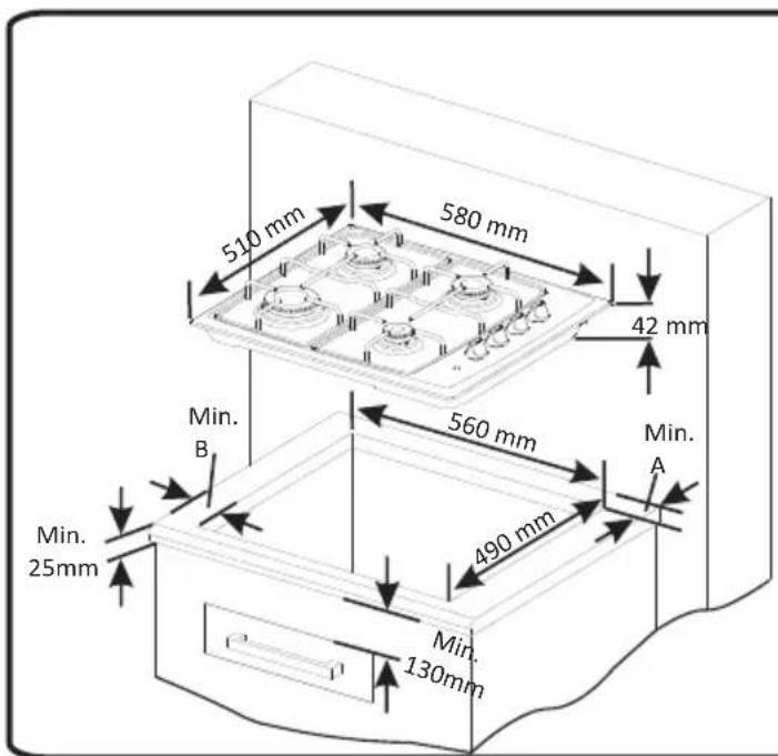
- Cut the aperture dimensions as indicated in Figure - 1. Locate the aperture on the worktop such that after the hob is installed the following requirements are ensured;
• 100mm from edge of cooker to combustible materials
• 700mm underside of overhead cupboards, shelving
• 750mm underside of overhead extractor fans.
text_image
510 mm 580 mm 42 mm 560 mm Min. B 490 mm Min. A Min. 25mm Min. 130mm| Neighbourhood walls | A[mm] | B[mm] |
| Combustible | 60 | 150 |
| Non-combustible | 40 | 50 |
Figure 1
3. INSTALLATION AND PREPARATIONS FOR USE
- Apply the adhesive sealing material "C" all the way round the aperture on the worktop to match the outer perimeter edge of the appliance. Ensure that the junctions overlap at the corners and no gap is left along the sealing material.
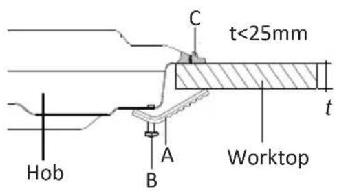
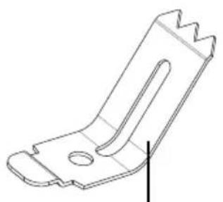
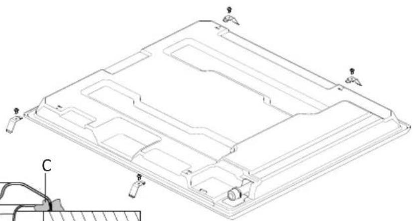
- Check the type of the brackets supplied in the assembly kit in Figure-2 and Figure-3 and continue accordingly;
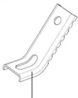
Brackets of Type-1
Insert the appliance into the aperture and fix in position via the brackets (A) and screws (B). Adjust the position of the brackets depending on the thickness of the worktop as indicated in Figure-2 and tighten the screws evenly.
natural_image
Technical line drawing of a metal bracket with scalloped edges and a hole (no text or symbols)Bracket Type 1
text_image
C t<25mm Hob A B Worktop t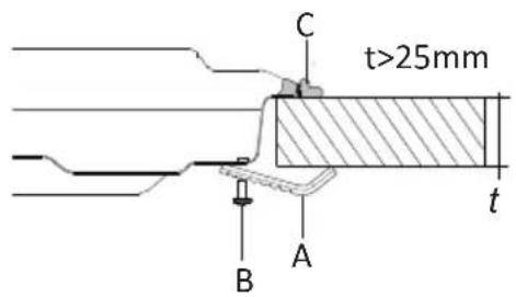
text_image
C t>25mm B A tFigure 2 - Installation with Bracket Type 1
Brackets of Type-2
Fix the brackets (A) via the screws (B) on the bottom cover of the appliance as shown in Figure-3. Insert the appliance into the aperture and apply pressure on the cooktop, ensure the appliance is positioned tightly.
natural_image
Technical line drawing of a mechanical bracket component (no text or symbols)Bracket Type 2
natural_image
Technical line drawing of a mechanical component with mounting holes and internal channels (no text or symbols)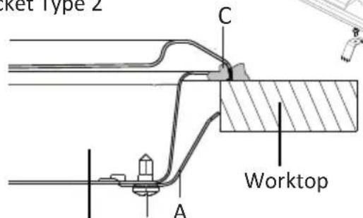
text_image
Ricket Type 2 C Worktop AHob
Figure 3 - Installation with Bracket Type 2
3. INSTALLATION AND PREPARATIONS FOR USE
- Carefully trim away the excess sealing material "C" from around the appliance.

Important: If the appliance is to be installed above a cupboard or drawer it is absolutely essential that you place a separator between the base of the appliance and the drawer unit.
Emptying of the Burned Gases from Environment
The cooking appliances that operate with gas, throw the burned gas wastes out directly to the outside or through the cooker hoods that are connected to the a chimney that opens directly to the outside. If it seems that it is not possible to install a cooker hood, it is required to set an electric fan on the window or wall that has access to fresh air. This electric fan must have the capacity to change the air of the kitchen environment 4-5 times of its own volume of air per hour.
3.2. Gas connection
The connection of the appliance should be performed in accordance with local and international standards and regulations applicable. You can find the information related to appropriate gas types and appropriate gas injectors on technical data table. If the pressure of used gas is different than these values stated or not stable in your area, it may be required to assemble an available pressure regulator on the gas inlet. It is certainly required to contact to the authorized service to make these adjustments.
The points that must be checked during flexible hose assembly
If the gas connection is made by a flexible hose that is fixed on the gas inlet of appliance, it must be fixed by a pipe collar as well. Connect your appliance with a short and durable hose that is as close as possible to the gas source. The hose's permitted maximum lenght is 1.5m. The hose that brings gas to the appliance must be changed once a year for your safety.
The hose must be kept clear from areas that may heat up to temperatures in excess of 90^ C. The hose must not be ruptured, bent or folded. It must be kept clear of sharp corners, moving things, and should not be defective. Before assembly, it must be checked whether there is any production defect.
As gas is turned on, all connection parts and hose must be checked with soapy water or leakage fluids. Do not use naked flame to check gas leakage. All metal components used during gas connection must be clear of rust. Also check the expiry dates of components to be used.
The points that must be checked during fixed gas connection assembly
To assemble a fixed gas connection (gas connection made by threads, e.g. a nut), there are different methods used in different countries. The most common parts are already supplied with your appliance. Any other part can be supplied as spare part.
3. INSTALLATION AND PREPARATIONS FOR USE
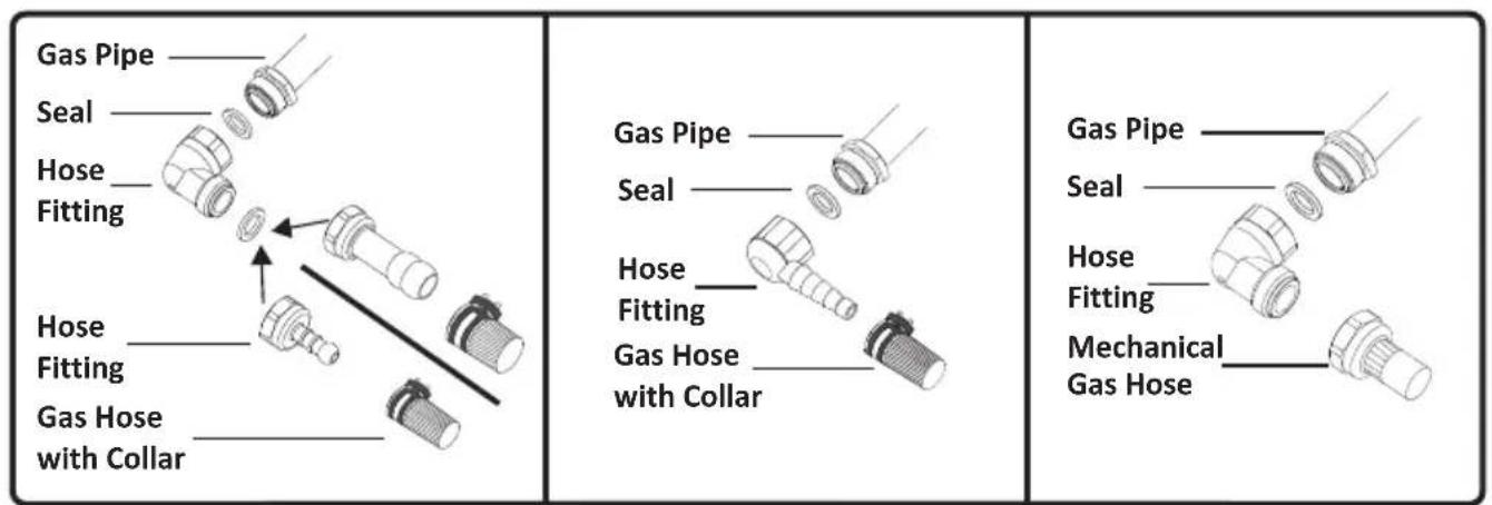
During connections always keep the nut on the gas manifold fixed, while rotating the counter-part. Use spanners of appropriate size for safe connection. For all surfaces between different components, always use the seals provided in the gas conversion kit. The seals used during connection should also be approved to be used in gas connections. Do not use plumbing seals for gas connections.
Remember that this appliance is ready to be connected to gas supply in the country for which it has been produced. The main country of destination is marked on the rear cover of the appliance. If you need to use it in another country, any of the connections in the figure below can be required. In such a case, contact local authorities to learn the correct gas connection.
text_image
Gas Pipe Seal Hose Fitting Hose Fitting Gas Hose with Collar Gas Pipe Seal Hose Fitting Gas Hose with Collar Gas Pipe Seal Hose Fitting Mechanical Gas Hose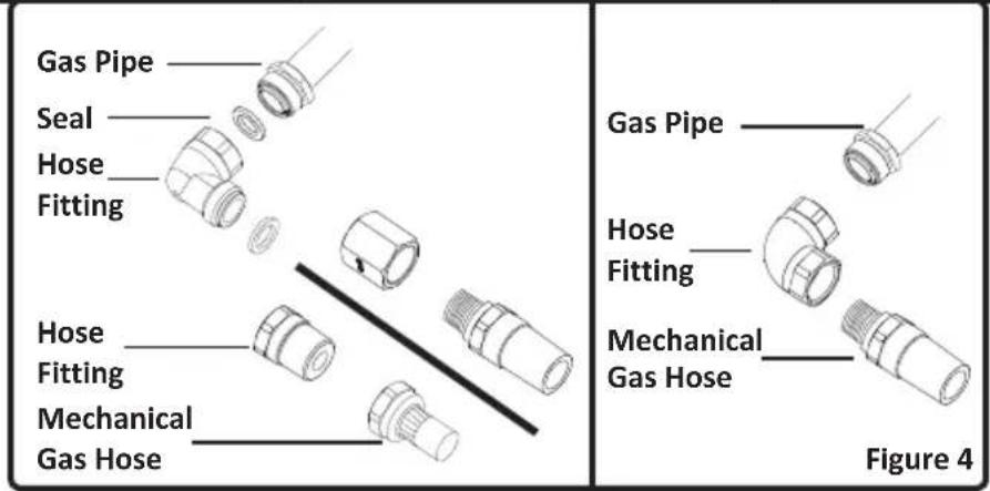
text_image
Gas Pipe Seal Hose Fitting Hose Fitting Mechanical Gas Hose Gas Pipe Hose Fitting Mechanical Gas Hose Figure 4It is required to call the authorized service to be able to make the gas connections appropriately and in compliance with safety standards.

ATTENTION! Surely do not use any match or lighter for control of gas leakage.
3.3. Electric connection and safety
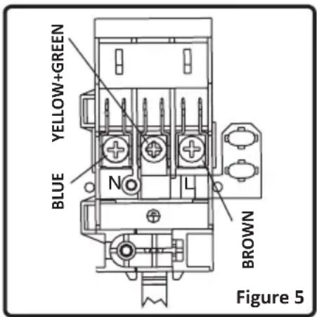
During the electric connection, follow the instructions stated in the user manual.
- The earthing cable must be connected to the earth terminal
-
You have to ensure the power cord with suitable insulation to be connected to the power source during the connection. If there is no appropriate earthed electric outlet in accordance with regulations in the place where the appliance to be installed, contact to our authorized service. The earthed electric outlet must be close to the appliance.
-
Do not use an extension cord
- The power cord must not touch to the hot surface of the product.
- In case the cord is damaged, contact Authorized Service to have it changed.
- Any wrong electric connection may damage your appliance, as well as endangering your safety, rendering your guarantee invalid.
- The appliance is adjusted for 230V 50Hz electricity. If the mains electricity is different contact your authorized service.
text_image
YELLOW+GREEN BLUE N L BROWN Figure 5- The supply cord should be kept away from hot parts of appliance. Otherwise, the cord may be damaged, causing short circuit.
- The manufacturer declares that it has no responsibility against any kind of damages and losses that are caused by improper connections that are performed by unauthorized people.
3.4 Gas conversion
Caution: The following procedures must be undertaken by authorized service people.
Your appliance is adjusted to be operated with LPG/NG gas. The gas burners can be adapted to different types of gas, by replacing the corresponding injectors and adjusting minimum flame length suitable to the gas in use. For this purpose, following steps should be performed:
Changing injectors:
- Cut off the main gas supply and unplug from the electric mains
- Remove the burner cap and the adapter(Figure 6).
- Unscrew the injectors. For this, use a 7mm spanner(Figure 7).
- Replace the injector with the ones from the gas conversion kit, with corresponding diameters suitable to the type of gas that is going to be used, according to the information chart (which is also supplied in the gas conversion kit).
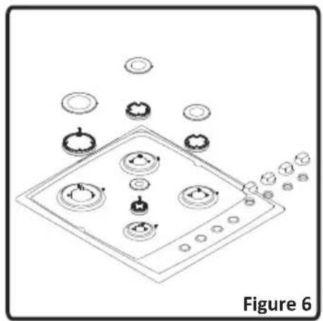
natural_image
Isometric line drawing of a kitchen appliance with multiple kitchen utensils and a stove (no text or symbols)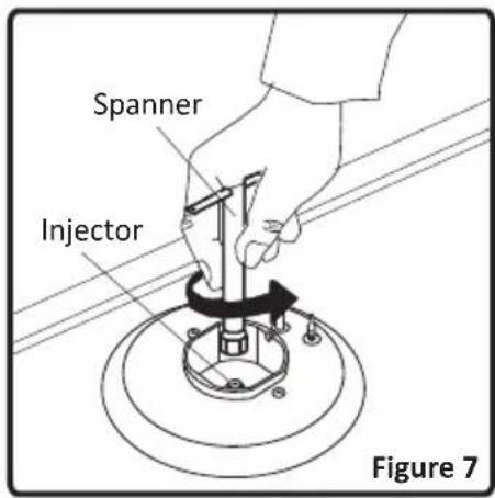
text_image
Spanner Injector Figure 7Adjusting the reduced flame position:
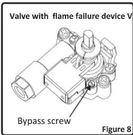
The flame length in the minimum position is adjusted with a flat screw located on the valve. For valves with flame failure device, the screw is located on the side of the valve spindle (Figure 8-9). For valves without flame failure device, the screw is located inside the valve spindle (Figure 10). For easier reduced flame adjustment, it is advised to remove the control panel (and microswitch, if present) during adjustment.
To determine the minimum position, ignite the burners and leave them on in minimum position. Remove the with the help of a small screwdriver fasten or loosen the bypass screw around 90 angular degrees. When the flame has a length of at least 4mm, the gas is well distributed. Make sure that the flame does not die out when passing from the maximum position to the minimum position. Create an artificial wind with your hand toward the flame to see if the flames are stable.
text_image
Valve with flame failure device V Bypass screw Figure 8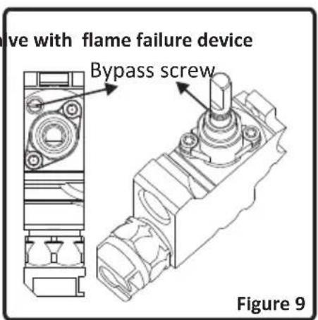
text_image
ave with flame failure device Bypass screw Figure 9Changing the gas inlet:
For some countries, the gas inlet type can be different for NG/LPG gases. In such a case, remove the current connection components and nuts (if any) and connect the new gas supply accordingly. In all conditions, all components used in gas connections should be approved by local and/or international authorities. In all gas connections, refer to the “Assembly of gas supply and leakage check” clause explained before.
4. USE OF YOUR PRODUCT
4.1 Use of gas burners
Ignition of the burners
To determine which knob controls which burner, check the position symbol above the knob.
- Manual Ignition
If your appliance is not equipped with any ignition aid or in case there is a failure in the electric network, follow the procedures listed below:
To ignite one of the burners, press and turn its knob counter-clockwise so that the knob is in maximum position, approach a match, taper or another manual aid to its upper circumference. Move the ignition source away as soon as you see a stable flame.
- Electrical Ignition
natural_image
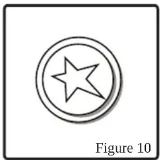
Simple line drawing of a five-pointed star inside a circle, labeled 'Figure 10' (no text or symbols on the diagram itself)Ignition by Spark Button: Press the valve of the burner you want to operate and turn the valve in the counter-clockwise direction so that the knob is in maximum position and with your other hand, press the ignition button (Figure 10) at the same time. Press the ignition button immediately, because if you wait, a build up of gas may cause the flame to spread. Continue pressing the ignition button until you see a stable flame on the burner.
Flame safety device:
Hob Burners (If your product is equipped with gas safety device)
Hobs equipped with flame failure device provide security in case of accidentally extinguished flame. If such a case occurs, the device will block the burners gas lines and will avoid any accumulation of unburned gas. Wait 90 seconds before re-igniting an extinguished gas burner.
Control of the hob burners
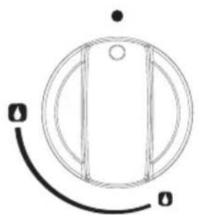
natural_image
Simple line drawing of a circular object with internal vertical structure and two curved lines labeled 'a' at the bottom (no text or symbols beyond labels)OFF position
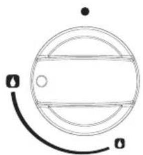
natural_image
Simple line drawing of a circular object with horizontal bands and a curved line, no text or symbols present.MAX. position
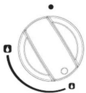
natural_image
Simple line drawing of a circular device with internal components and a curved arrow, no text or symbols present.MIN. position
natural_image
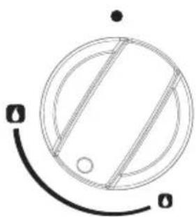
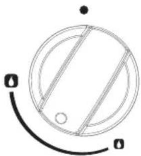
Simple circular diagram with diagonal lines and a curved line, no text or symbols presentMODULATE
Figure 11
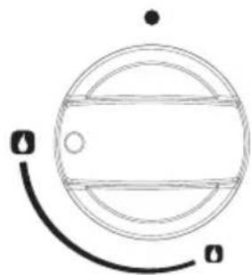
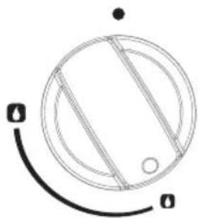
The knob has 3 positions: Off (0), maximum (big flame symbol) and minimum (small flame symbol). After you ignite the burner in maximum position; you can adjust the flame length between maximum and min. positions. Do not operate the burners when the knob position is between maximum and off positions.
text_image
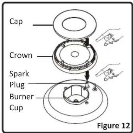
Cap Crown Spark Plug Burner Cup Figure 12After the ignition, check the flames visually. If you see yellow tip, lifted or unstable flames; turn the gas flow off, and check the assembly of burner caps and crowns (Figure 12). Also, make sure that no liquid has flown into the burner cups. If the burner flame goes out accidentally, turn the burner off, ventilate the kitchen with fresh air, and do not attempt re-ignition for 90 sec.
When turning the hob off, turn the knob in the clockwise direction so that the knob shows "0" position or the marker on the knob points upwards.
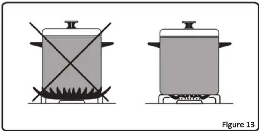
Your hob has burners of different diameters. The most economic way of using gas is to choose the correct size gas burners for your cooking pan size and to bring the flame to minimum position once the boiling point is reached. It is recommended to always cover your cooking pan.
In order to obtain maximum performance from the main burners, use pots with the following flat bottom diameters. Using smaller pots than the minimum dimensions stated below will cause energy loss.
Rapid Burner: 22-26cm
Semi-rapid Burner: 14-22cm
Auxiliary Burner: 12-18cm
4. USE OF YOUR PRODUCT
Make sure that the tips of the flames do not spread out of the outer circumference of the pan, as this may also harm the plastic accessories around the pan (handles etc.).
natural_image
Two identical cooking pots with crossed handles on their bases, placed side by side (no text or symbols)When the burners are not in use for prolonged periods, always turn the main gas control valve off.

Warning:
• Use only flat pans and with a sufficiently thick base.
- Ensure that the base of the pan is dry before placing it on the burners.
- The temperature of accessible parts may be high when the appliance is operating. So it is imperative to keep children and animals out of the reach of the burners during and after cooking.
- After use, the hob remains very hot for a prolonged period of time, do not touch it and do not place any object on top of the hob.
- Never place knives, forks, spoons and lids on the hob as they will get hot and could cause serious burns.
5. CLEANING AND MAINTENANCE
5.1 Cleaning
Be sure that all control switches are off and your appliance cooled before cleaning your oven. Plug off the appliance. Check whether they are appropriate and recommended by the manufacturer before using the cleaning materials on your oven. As they may damage the surfaces, do not use caustic creams, abrasive cleaning powders, thick wire wool or hard tools. In case the liquids that overflow around your oven burn, the enameled parts may be damaged. Immediately clean the overflown liquids.
Cleaning of Your Hob
- Lift up the pan supports, caps and crowns of hob burners(Figure 12).
- Wipe and clean the back panel with a soapy cloth.
- Wash the caps and crowns of hob burners and rinse them. Do not leave them wet, immediately dry them with paper cloth.
• After cleaning, make sure that you re-assemble the parts correctly. - Do not clean any part of the hob with metal sponge. It causes the surface be scratched.
- The pan support top surfaces may be scratched in time due to usage. These parts will not get rusted and it is not a production fault.
- During cleaning of the hob plate, make sure that no water flows inside the burner caps, as this may block the injectors.
Burner Caps:
Periodically, enameled pan support, enameled covers, burner heads must be washed with soapy warm water rinsed and dried. After drying them thoroughly, replace them correctly.
Enamelled Parts:
In order to keep them a new, it is necessary to clean them frequently with mild warm soapy water and then dry with cloth. Do not wash them while hot and never use abrasive powders or abrasive cleaning materials. Do not leave vinegar, coffee, milk, salt, water, lemon, or tomato juice to remain in contact with enameled parts for long periods of time.
Stainless Steel:
Stainless steel parts must be cleaned frequently with mildly warm soapy water and a soft sponge and then dry with a soft cloth. Do not use abrasive powders or abrasive cleaning metarials. Do not leave vinegar, coffee, milk, salt, water, lemon or tomato juice to remain in contact with stainless steel parts long periods of time.
5. CLEANING AND MAINTENANCE
5.2 Maintenance
Periodically check the gas connection pipe. Even if any simple abnormality is felt, inform the technical service to have it changed. We recommend the gas connection parts to be changed once a year. If any abnormality is felt while operating the control knobs of cooker, contact to the authorized service.
6. SERVICE AND TRANSPORT
6.1 Basic troubleshooting before contacting service
If the electrical ignition/hotplate does not operate :
• The hob may be plugged off, there has been a black out.
If the hotplate does not heat :
• The heat may be not adjusted correctly with hob heater control switch.
The hob burners do not operate correctly :
- Check if the burner parts are correctly assembled(especially after cleaning).
- The gas supply pressure may be too low/high. For appliances working with bottled LPG, the LPG cylinder may be depleted.
Except these, if you still have any problem with your product, please call to the Authorized Service.
6.2 Information related to transport
If you need any transport; keep the original case of product and carry it with its original case when needed to be carried. Follow the transport signs on packaging. Tape the hob on upper parts, caps and crowns and pan supports to the cooking panels.
If you do not have the original packaging; prepare a carriage box so that the appliance, especially external surfaces (glass and painted surfaces) of oven is protected against external threats.
| G30 28-30mbar 7.5kW 545g/hII2H3+ IEClass: 3 | LPGG30/G3128-30/37 mbar | NGG2020 mbar |
| LARGE BURNER | ||
| INJECTOR (1/100mm) 85 115 | ||
| NOMINAL RATING (KW) 3 3 | ||
| CONSUMPTION IN 1h 218.1 g/h 285.7 l/h | ||
| MEDIUM BURNER | ||
| INJECTOR (1/100mm) 65 97 | ||
| NOMINAL RATING (KW) 1.75 1.75 | ||
| CONSUMPTION IN 1h 127.2 g/h 166.7 l/h | ||
| SMALL BURNER | ||
| INJECTOR (1/100mm) 50 72 | ||
| NOMINAL RATING (KW) 1 1 | ||
| CONSUMPTION IN 1h 72.7 g/h 95.2 l/h | ||
The symbol on the product or on its packaging indicates that this product may not be treated as household waste. Instead it shall be handed over to the applicable collection point for the recycling of electrical and electronic equipment. By ensuring this product is disposed of correctly, you will help prevent potential negative consequences for the environment and human health, which could otherwise be caused by inappropriate waste handling of this product. For more detailed information about recycling of this product, please contact your local city office, your household waste disposal service or the shop where you purchased the product.
NORDMENDE™
HG62IX
HG62BL
BETRIEBS-UND
natural_image
Front view of a four-gas stove with four panes and control knobs (no visible text or symbols)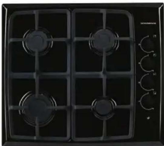
natural_image
Front view of a black gas stove with four vented grilles and control knobs (no visible text or symbols)Werte Kunden,
| Neighbourhood walls | A[mm] | B[mm] |
| Combustible | 60 | 150 |
| Non-combustible | 40 | 50 |
Abb. 1
natural_image
Illustration of a gas stove with four fans and surrounding circular components (no text or symbols)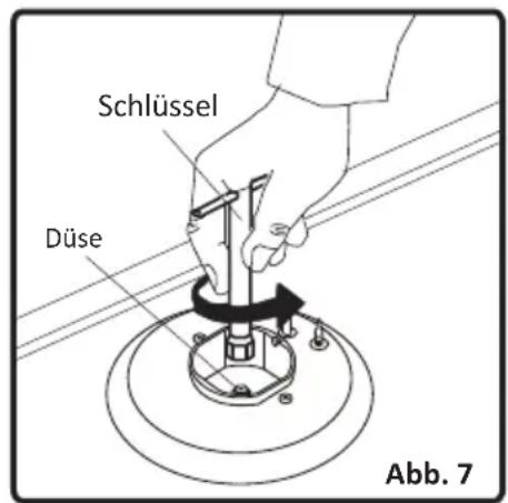
text_image
Schlüssel Düse Abb. 7natural_image
Simple line drawing of a five-pointed star inside a circle, labeled 'Abb. 10' below (no other text or symbols)natural_image
Simple line drawing of a circular object with internal vertical structure and two curved lines labeled 'a' at the bottom (no text or symbols beyond labels)Aus-Stellung
natural_image
Simple line drawing of a circular object with horizontal bars and a curved line, no text or symbols present.MAX-Stellung
natural_image
Simple line drawing of a circular device with internal components and a curved arrow, no text or symbols present.MIN-Stellung
natural_image
Simple circular diagram with diagonal lines and a curved line, no text or symbols presentMODULIEREN
Abb. 11