
DMR-2840SET - Security Camera Monacor - Free user manual and instructions
Find the device manual for free DMR-2840SET Monacor in PDF.


User questions about DMR-2840SET Monacor
0 question about this device. Answer the ones you know or ask your own.
Ask a new question about this device
Download the instructions for your Security Camera in PDF format for free! Find your manual DMR-2840SET - Monacor and take your electronic device back in hand. On this page are published all the documents necessary for the use of your device. DMR-2840SET by Monacor.
USER MANUAL DMR-2840SET Monacor
Safety Instruction 4
Chapter 1 Features....1
Chapter 2: Overview....2
2.1 Front Panel.... 2
2.1.1、4CH CIF/D1 DVR Front Panel.... 2
2.1.2、8CH CIF DVR Front Panel....3
2.1.3、D9216H(CIF)/D9016H(CIF)/D9608L(D1)/D9616L(D1) DVR Front Panel....4
2.1.4、D9216H(33) CIF DVR Front Panel....5
2.1.5、D9316H(2U) CIF DVR Front Panel....6
2.2 Rear Panel....7
2.2.1、4CH-CIF/D1 DVR Back Panel....7
2.2.2、4CH-CIF/D1 DVR Back Panel....8
2.2.3、8CH-CIF DVR Back Panel....8
2.2.4、8CH-CIF DVR Back Panel....9
2.2.5、8CH-D1 DVR Back Panel 9
2.2.6、16CH-CIF DVR Back Panel.... 10
2.2.7、16CH-D1 DVR Back Panel....11
2.2.8、16CH(33)-CIF DVR Back Panel.... 11
2.2.9、16CH(2U)-CIF DVR Back Panel 12
2.3 4/8-CH Remote Controller .... 13
2.4 16-CH Remote Controller.... 14
Chapter 3 DVR INSTALLATION....16
3.1 HDD Installation (Applicable to the model with HDD drawer) 16
3.2 Camera and Monitor Connection.... 16
3.3 Power Supply connection.... 16
Chapter 4: DVR Boot up ....17
4.1 System Initialization 17
4.2 Live Interface....17
Chapter 5: DVR Menu....17
5.1 Pop-up Menu 17
5.2 Main Menu Guide....18
5.3 Main Menu....19
5.3.1 Display.... 19
5.3.2 Record set 21
5.3.3 Search 23
5.3.4 Network 27
5.3.5 Alarm 30
5.3.6 Device 32
5.3.7 System.... 34
5.3.8 Advanced 36
5.4 Menu Lock....37
5.5 Split mode 37
5.6 PTZ Control....37
5.7 PIP Mode 38
5.8 Record search.... 38
5.9 Mute 39
5.10 Manual Record.... 39
5.11 Stop record.... 39
5.12 Start Sequence 39
5.13 Start Cruise 39
Chapter 6: Web Application Manager....40
6.1 Plug-in download and installation 40
6.2 Web Application Manager Log-in....41
6.3 Live interface 41
6.3.1 Menu Bar 41
6.3.2 Playback....43
6.3.3 Configuration.... 46
6.3.4 Local setting.... 55
6.3.5 Logout.... 55
Chapter 7: Appendix....56
7.1 Operation Function Table 56
7.2 Record Alarm setting.... 57
7.3 Mail box server List....57
7.4 Troubleshooting....58
7.5 Usage Maintenance.... 59
7.6 System Connection Diagram 59
7.7 Accessories 63
Safety Instruction
1. Read Instruction
All the safety and operating instruction should be read before the equipment is operated.
2. Power sources
This equipment should be operated only from the type of power source indicated on the marking label. If you are not sure of the type of power, please consult your equipment dealer.
3. Objects and Liquid
Never push objects of any kind through openings of this equipment and / or spill liquid of any kind on the equipment as they may touch dangerous voltage points or short out parts that could result in a fire or electric shock.
4. Water and / or Moisture
Do not use this equipment near water or in contact with water.
5. Heat sources
Do not install near any heat sources such as radiators, heat registers, stoves or other apparatus (including amplifier) that produce heat.
6. Dusty field
Never use this equipment near dusty or intense magnetic field.
7. Cleaning
Unplug this equipment from the wall outlet before cleaning it. Do not use liquid aerosol cleaners. Use a damp soft cloth for cleaning.
8. Lightning
Unplug this equipment during lightning storm or when unused for long periods of time.
9. Accessories
Do not place this equipment on an unstable cart, stand or table. When a cart is used, use caution when moving the cart / apparatus combination to avoid injury from tip-over.
10.Moving
Disconnect the power before moving the equipment. And the equipment should be moved with care.
11. Attachment
Never add any attachments and/or equipment without the approval of the manufacturer as such additions may result in the risk of fire, electric shock and other personal injury.
12. Correct Batteries
Risk of explosion occurs if battery is replaced by an incorrect type. Therefore you must use the same type of battery as the one being used in the product.
13. Ventilation.
Do not block any ventilation openings, installation of the equipment in the rack should be such that the amount of airflow required for safe operation of the equipment is not compromised.
14. Overloading
Do not overload wall outlets and extension cords to avoid the risk of fire or electric shock.
15. Reliable Earthlings (Grounding)
Reliable grounding of rack mounted equipment should be maintained. Particular attention should be given to supply connections other than direct connections to the branch circuit.
Chapter 1 Features
| Function Brief and Description | |
| Real time monitoring | Double video output; with monitor, VGA virtual output port or HDMI Output; Support net-viewer and MP live surveillance and also support zoom in/out, auto sequence and PIP display. |
| Record | H.264 video compression format; record quality/resolution/frame rate adjustable, multiple record modes (Always, Scheduled, Manual, Alarm, Motion detection and remote record) |
| Record storage | Support SATA large capacity HDD and save real-time record image to HDD. |
| Playback | Support DVR single CH and multiple CH Search/Playback of recorded files. |
| Backup | Support DVR backup via USB flash drive, removable drive, Recorder and network. |
| Alarm Setting | Supports HDD & video input alarm management and external alarm signal inputs. |
| Network operation | Supports remote surveillance by authority users to increase system security. |
| Mouse Operation | Supports Mouse operation for faster menu navigation. |
| PTZ Control | Supports PTZ camera operations through RS-485. |
List 1-1
Features :
H. 264 video compression format; supports D1 resolution;
G.711 audio compression format
Windows Graphical interface; embedded real-time Linux2.6 operation system;
Friendly Menu reminder;
Multiple operation modes (Preview, record, playback, backup, network surveillance and mobile phone monitoring);
Supports Double Encode bit network transmission;
Supports remote live surveillance via 3G mobile networks;
Supports Zoom in/out and sequence function;
The video package time is adjustable;
Multiple alarm record modes;
Rear USB2.0 ports for back-up, upgrade and mouse operation;
With IR remote control operation;
Multiple language OSD;
Support auto-maintain.
Chapter 2: Overview
2.1 Front Panel
Reminder: DVR is the abbreviation of Digital Video Recorder Equipment.
2.1.1、4CH CIF/D1 DVR Front Panel
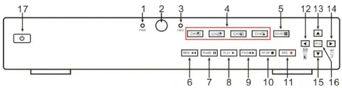
text_image
17 1 2 3 4 5 12 13 14 PWM HDD CH1 CH2 CH3 CH4 QUAD ▲ 6 7 8 9 10 11 15 16 REIN ← PAUSE → PLAY → FWD → STOP → REC → OFF PTZ + - + - + - + - + - + - + - + - + - + - + - + - + - + - + - + - + - + - + - + - + - + - + - + - + -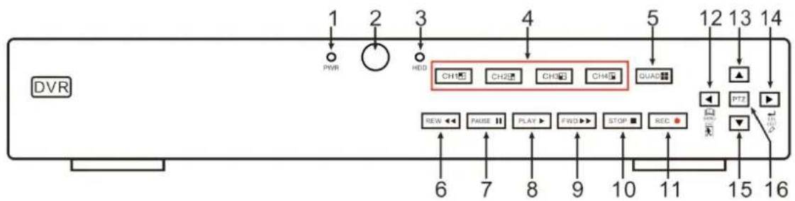
text_image
DVR 1 PWR 2 HDD 4 CH1 CH2 CH3 CH4 QUAD 5 12 13 14 ▲ PTZ ▶ 6 7 8 9 10 11 15 16 REC REW ←← PAUSE → PLAY → FIND→ STOP → REC| Item | Key title or Indicator | Remark | Function & Description |
| 1 Power Indicator PWR | If the “Green” indicator is on the system is getting power normally. | ||
| 2 IR | Receiver | ● | Receives IR signal from Remote Controller |
| 3 HDD Indicator HDD | When the “Red” indicator flashes it means the hard drive is being read or written to. | ||
| 4 | Channel select:CH1 CH2CH3 CH4 | [AHG (TZ5X)] | CH select key |
| 5 QUAD | ### | On Live or Playback mode, switch to Quad display. | |
| 6 REW | ◀◀ | Move to left; Rewind function;decrease PTZ rotation speed and parameter value;On preview mode, holding pressing the button to switch GUI operation device | |
| 7 PAUSE | II | Pause / play frame by frame manually | |
| 8 PLAY | ▶ | Enter into Pop-up Menu; Play record file. | |
| 9 FWD | ▶▶ | Right key, F. Forward key; increase PTZ rotation speed | |
| 10 STOP | ■ | Stop playing or stop manual record | |
| 11 REC ● | Press the button to start manual record. | ||
| 12 MENU/ESC | ◀ | Enter into Main menu, exit or stop playing | |
| 13 Up key | ▲ | Move up | |
| 14 SEL/EDIT | ▶ | select [Enter] / [Edit] operation | |
| 15 Down key | ▼ | Move down | |
| 16 PTZ : | Enter | into PTZ control interface | |
| 17 Power button | 💡 | Power on/off | |
List 2-1
2.1.2、8CH CIF DVR Front Panel
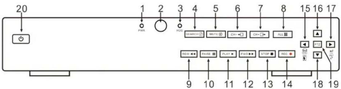
text_image
20 1 2 3 4 5 6 7 8 15 16 17 PWR HCC SEARCH Ⓐ MUTE Ⓞ CH-←→ CH-→→ ALL ■ REW ←→ PAISE ■ PLAY →→ FWD →→ STOP ■ REC ● 9 10 11 12 13 14 18 19 ▲ PTZ ▼ TEN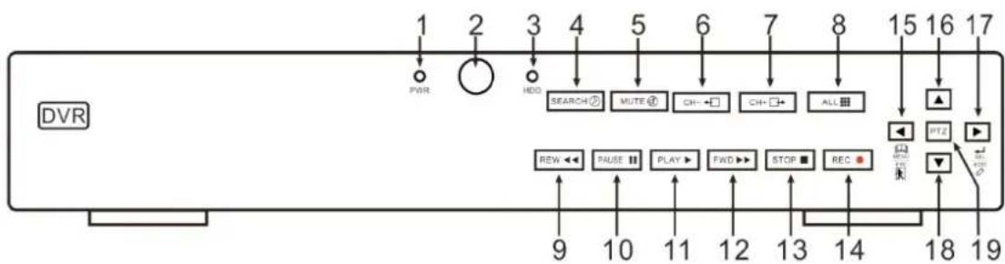
text_image
DVR 1 2 3 4 5 6 7 8 15 16 17 PWR HDD SEARCH MUTE CH CH ALL REW PAUSE PLAY FWD STOP REC 9 10 11 12 13 14 18 19| Item | Key title or Indicator | Remark | Function & Description |
| 1 Power Indicator PWR | If the “Green” indicator is on the system is getting power normally. | ||
| 2 IR Receiver | ● | Receives IR signal from Remote Controller | |
| 3 HDD Indicator HDD | When the “Red” indicator flashes it means the hard drive input. | ||
| 4 SEARCH | ∅ | Record search | |
| 5 MUTE | ∅ | Open or close audio input | |
| 6 CH- | → | Switch to previous channel | |
| 7 CH+ | → | Switch to next channel | |
| 8 QUAD | ■■ | Quad display mode | |
| 9 REW | ◀ | Move to left; Rewind function; decrease PTZ rotation speed and parameter value; On preview mode, holding pressing the button to switch GUI operation device | |
| 10 PAUSE | II | Pause / play frame by frame manually | |
| 11 PLAY | ▶ | Enter into Pop-up Menu; Play record file. | |
| 12 FWD | ▶ | Right key, F. Forward key; increase PTZ rotation speed and | |
| 13 STOP | ■ | Stop playing or stop manual record | |
| 14 REC ● | Press the button to start manual record. | ||
| 15 | MENU/ESC | ◀ | Enter into Main menu, exit or stop playing |
| 16 Up key | ▲ | Move up | |
| 17 SEE/EDIT | ▶ | select [Enter] / [Edit] operation | |
| 18 | DOWN Key | ▼ | Move down |
| 19 | PTZ : | Enter into PTZ control interface | |
| 20 Power button | ➊ | Power on/off | |
List 2-2
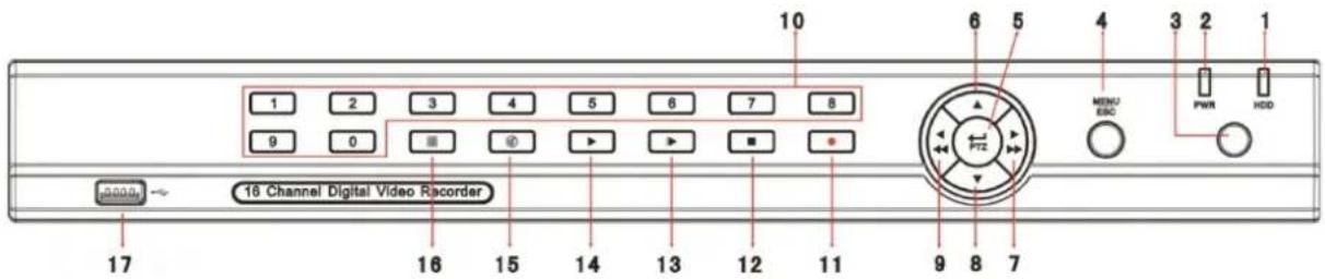
2.1.3、D9216H(CIF)/D9016H(CIF)/D9608L(D1)/D9616L(D1) DVR Front Panel
text_image
10 1 2 3 4 5 6 7 8 9 0 ■ ⊕ ► ► ■ - 6 5 4 3 2 1 MENU EBC PWR HDD 16 Channel Digital Video Recorder 17 16 15 14 13 12 11 9 8 7| Item | Type | Key title /Indicator | Marks | Function |
| 1 | Indicator | HDD indicator HDD | When the “Red” indicator flashes it means the hard drive is being read or written to. | |
| 2 | Power indicator PWR | If the “Green” indicator is on the system is getting power normally. | ||
| 3 | IR Receiver | ● | Receives IR signal from Remote Control | |
| 4 | Complex Key | Menu | MENU/ESC | Enter into main menu / Exit |
| 5 | PTZ PTZ | Enter into PTZ control, select [Enter] / [Edit] operation | ||
| 6 | Direction Key | UP | ▲ | Move up |
| 7 | RIGHT ▶/▶ | Move right / FWD | ||
| 8 | DOWN | ▼ | Move down | |
| 9 | LEFT ◀ /◀ | Move left / RWD | ||
| 10 | Channel Select & numeric input | Single Channel and numeric key | Numeric key 0,1-9 and CH key CH1~9 | 1. Number 1~9 stand for numeric 1~9 and CH 1~9.2. CH11-CH16 select method: press firstly numeric key 1 and then other numeric key. For example CH16 select firstly press 1, and then press 6.3. Holding press key 0 for three seconds may convert current output device |
| 11 | Rec. | Manual record | ● | Press the button to start manual record. |
| 12 | Play Control | Stop | ■ | Stop playing and stop manual record |
| 13 | By frame | ▶ | Play frame by frame | |
| 14 | Play | ▶ | Convert to play status | |
| 15 | Mute | ⓧ | Open or close audio input | |
| 16 | Multi Display | ⓨ | Live display Quad mode, 9-split and 16-split mode | |
| 17 | USB Port Connect to USB2.0 port | |||
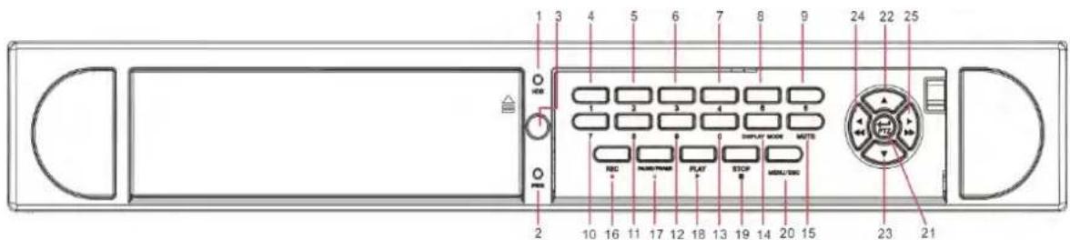
2.1.4、D9216H(33) CIF DVR Front Panel
text_image
1 3 4 5 6 7 8 9 24 22 25 HUB 1 2 3 4 5 6 DISPLAY ROOM MSETS NBC HUSB THISS PLAY STOP MENU/USB 2 10 16 11 17 12 18 13 19 14 20 15 23 21| Item | Type | Key title /Indicator | Marks | Function | |
| 1 | Indicator | HDD indicator HDD | When the “Red” indicator flashes it means the hard drive is being read or written to. | ||
| 2 | Power indicator PWR | If the “Green” indicator is on the system is getting power normally. | |||
| 3 | IR Receiver | ● | Receives IR signal from Remote Control | ||
| 4 | Channel Select & numeric input | Single Channel display and numeric key | 1 | CH-1 ; Numeric key 1 | CH11-CH16 select method: press firstly numeric key 1 and then other numeric key. Such as CH16 |
| 5 | 2 | CH-2 ; Numeric key 2 | |||
| 6 | 3 | CH-3 ; Numeric key 3 | |||
| 7 | 4 | CH-4 ; Numeric key 4 | |||
| 8 | 5 | CH-5 ; Numeric key 5 | |||
| 9 | 6 | CH-6 ; Numeric key 6 | |||
| 10 | 7 | CH-7 ; Numeric key 7 | |||
| 11 | 8 | CH-8 ; Numeric key 8 | display, firstly press 1, and then press 6.Note: Holding to press key 0 for three seconds may convert current output device | ||
| 12 | 9 | CH-9 ; Numeric key 9 | |||
| 13 | 0 | CH-10:Numeric key0 | |||
| 14 | Display | Multiple CH display | Display Mode | Live Quad display, 9-split display and 16-split display | |
| 15 | Audio control | Mute key MUTE Open or close audio input/output | |||
| 16 | Rec. | Manual record | ● | Press the button to start manual record. | |
| 17 | Play Control | Pause | PAUSE/FRAME | II Pause / play frame by frame | |
| 18 | Play | PLAY | Convert to play status | ||
| 19 | Stop | STOP ■ | Stop playing record | ||
| 20 | Complex Key | Menu MENU/ESC Enter into main menu / Exit | |||
| 21 | PTZ PTZ | Enter into PTZ control, select [Enter] / [Edit] operation | |||
| 22 | Direction Key | UP | ▲ | Move up | |
| 23 | DOWN | ▼ | Move down | ||
| 24 | LEFT | ◄ /◄ | Move left / RWD | ||
| 25 | RIGHT | ► /► | Move right / FWD | ||
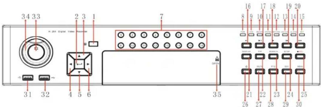
2.1.5、D9316H(2U) CIF DVR Front Panel
text_image
3 4 3 3 H. 204 Digital Video Receiver 1 2 3 1 7 3 1 3 2 4 5 6 3 5 OUTPUT 16 8 9 10 11 12 13 14 15 21 22 23 24 25 26 27 28 29 30| Item | Marks | Function |
| 1 | IR | Receives IR signal from Remote Control |
| 2 | ENTER | Select OK to operate |
| 3\4\5\6 | ▲▼◄► | Move up\down\left\right |
| 7 | 0~16 | Number key; Single Channel display |
| 8 | PWR | POWER indicator |
| 9 | HDD | HDD indicator |
| 10 | READY | Ready indicator |
| 11 | STATUS | Status indicator |
| 12 | RECORD | HDD video indicator |
| 13 | BACKUP | Backfile indicator |
| 14 | ALARM | Alarm indicator |
| 15 | NET | Net indicator |
| 16 | ◀ | Rewind |
| 17 Frame into ▶ | ||
| 18 | ▶ | Play |
| 19 Pause ▶ | ||
| 20 | ▶ | Fast Forward |
| 21 | DISPLAY | Multi-screen play;switch |
| 22 | PIP Picture in Picture function | |
| 23 | SEARCH | Search video |
| 24 | STOP | Stkey |
| 25 | REC | Video startyke |
| 26 | ◎ | Soft-switching key |
| 27 | MUTE | Mutcyke |
| 28 | PTZ | PTZpOperation |
| 29 | ESC | ESCyke |
| 30 | MENU | MENUyke |
| 31\32 | USB | USB |
| 33\34 | JOYSTICK | Shuttle ky |
| 35 | OPEN | pEn the revolution door |
2.2 Rear Panel
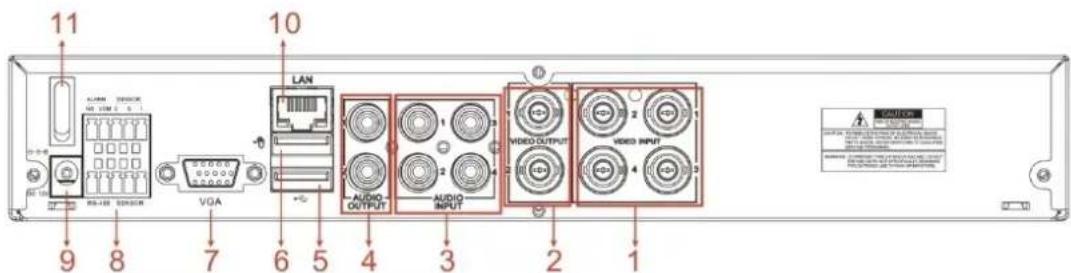
2.2.1、4CH-CIF/D1 DVR Back Panel
text_image
11 ALUMA SERVICE VGA LAN AUDIO OUTPUT AUDIO INPUT VIDEO OUTPUT VIDEO INPUT 9 8 7 6 5 4 3 2 1| Item | Physical port | Connection method |
| 1 | Video input | Connect CH1-4 (Virtual) video input device ( BNC interface ) |
| 2 | Video output Connect monitor output(BNC interface) | |
| 3 | Audio Input | 4CH audio input (BNC interface ) |
| 4 | Audio Output | 2CH output; RCA(interface ) |
| 5 | USB Port | Connect USB device (Flash Drive, Hard Drive and Recorder etc) |
| 6 | USB Port Connect USB mouse | |
| 7 | VGA Port Connect to VGA monitor, such as PC monitor (Optional) | |
| 8 | RS-485/Sensor/Alarm | RS485/Sensor/Alarm interface (see pin outs below) |
| 9 | Power Port Connect power supply - DC12V 3A | |
| 10 | Ethernet: Port Connect LAN, Ethernet (RJ45 interface) | |
| 11 | Power Switch Turn Power on and off | |
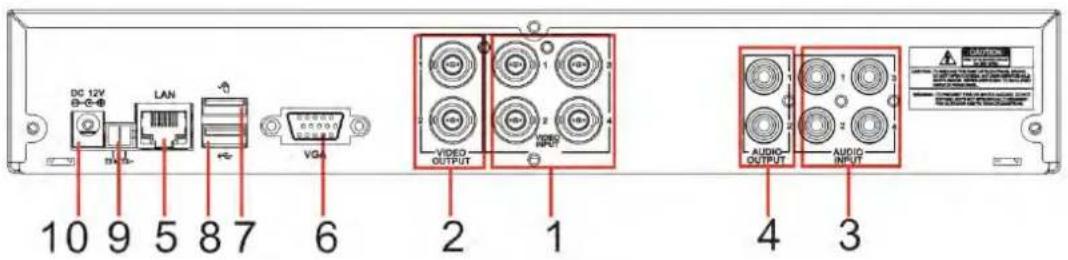
2.2.2、4CH-CIF/D1 DVR Back Panel
text_image
DC 12V LAN VGA 10 9 5 8 7 6 2 1 AUDIO OUTPUT AUDIO OUTPUT AUDIO INPUT 4 3| Item | Physical port | Connection method |
| 1 | Video input | Connect CH1-4 (Virtual) video input device ( BNC interface ) |
| 2 | Video output Connect monitor output (BNC interface) | |
| 3 | Audio Input | 4CH audio input (BNC interface ) |
| 4 | Audio Output | 2CH output; RCA(interface ) |
| 5 | Ethernet: Port Connect LAN, Ethernet (RJ45 interface) | |
| 6 | VGA Port Connect to VGA monitor, such as PC monitor (Optional) | |
| 7 | USB Port Connect USB mouse | |
| 8 | USB Port | Connect USB device (Flash Drive, Hard Drive and Recorder etc) |
| 9 | RS-485 RS485 interface | |
| 10 | Power Port Connect power supply - DC12V 3A | |
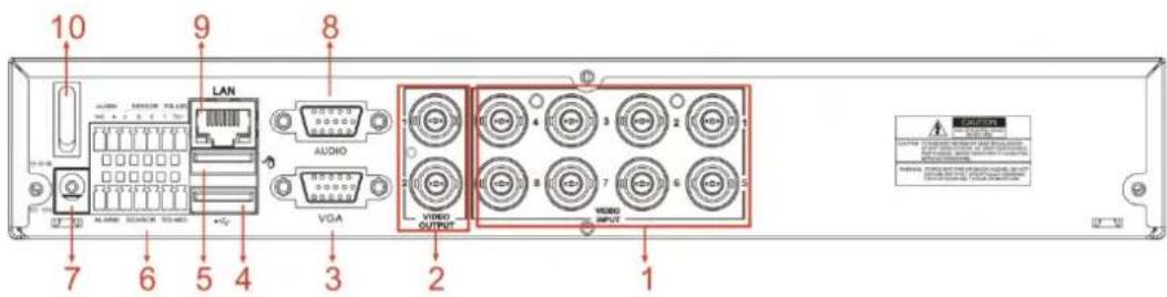
2.2.3、8CH-CIF DVR Back Panel
text_image
10 9 8 LAN AUDIO VGA VIDEO OUTPUT VIDEO INPUT 7 6 5 4 3 2 1| Item | Physical port | Connection method |
| 1 | Video input | Connect CH1-8 (Virtual) video input device ( BNC interface ) |
| 2 | Video output Connect monitor output (BNC interface) | |
| 3 | VGA Port Connect to VGA monitor, such as PC monitor (Optional) | |
| 4 | USB Port | Connect USB device (Flash Drive, Hard Drive and Recorder etc) |
| 5 | USB Port Connect USB mouse | |
| 6 | RS-485/Sensor/Alarm | RS485/Sensor/Alarm interface (see pin outs below) |
| 7 | Power Port Connect power supply - DC12V 3A | |
| 8 | Audio Input Audio input (BNC interface) | |
| 9 | Ethernet: Port Connect LAN, Ethernet (RJ45 interface) | |
| 10 | Power Switch | Turn Power on and off |
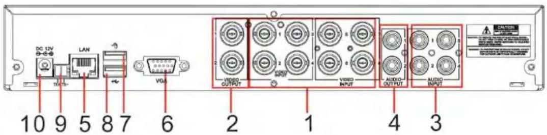
2.2.4、8CH-CIF DVR Back Panel
text_image
DC 12V LAN VGA 10 9 5 8 7 6 VIDEO OUTPUT VIDEO INPUT AUDIO OUTPUT AUDIO INPUT 1 2 3 4 3 DANTILE 1 2 3| Item | Physical port | Connection method |
| 1 | Video input | Connect CH1-8 (Virtual) video input device ( BNC interface ) |
| 2 | Video output Connect monitor output (BNC interface) | |
| 3 | Audio Input | 4CH audio input (BNC interface ) |
| 4 | Audio Output | 2CH output; RCA(interface ) |
| 5 | Ethernet: Port Connect LAN, Ethernet (RJ45 interface) | |
| 6 | VGA Port Connect to VGA monitor, such as PC monitor (Optional) | |
| 7 | USB Port Connect USB mouse | |
| 8 | USB Port | Connect USB device (Flash Drive, Hard Drive and Recorder etc) |
| 9 | RS-485 RS485 interface | |
| 10 | Power Port Connect power supply - DC12V 3A | |
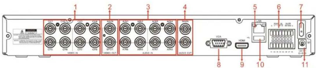
2.2.5、8CH-D1 DVR Back Panel
text_image
1 2 3 4 5 6 7 8 9 10 11 VGA HDMI LAN VISA AUDIO IN AUDIO OUT CHS CHB CHD CHF CHG CHI CHJ CHK CHL CHM CHN CHO CHP CHQ CHR CHS CHN CHD CHF CHG CHL CHM CHN CHQ CHL CHM CHN CHL CHM CHQ CHL CHM VISA| Item | Physical port | Connection method |
| 1 | Video input | Connect CH1-8 (Virtual) video input ( BNC interface ) |
| 2 | Video output | (UP) Main video output; (Down) Spot output (BNC interface) |
| 3 | Audio Input | 8CH audio input (BNC interface ) |
| 4 | Audio output | 2CH output; BNC (interface ) |
| 5 | Ethernet: Port Connect LAN, Ethernet (RJ45 interface) | |
| 6 | RS-485/Sensor/Alarm | RS485/Sensor/Alarm interface (see pin outs below) |
| 7 | Power Switch Turn Power on and off | |
| 8 | VGA Port Connect to VGA monitor, such as PC monitor | |
| 9 | HDMI HDMI Output | |
| 10 | USB Port Connect USB | mouse |
| 11 | Power Port | Connect power supply - DC12V 5A |
2.2.6、16CH-CIF DVR Back Panel
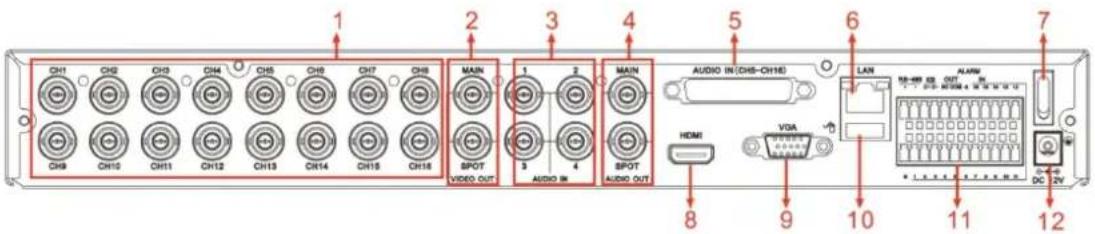
text_image
1 2 3 4 5 6 7 CH1 CH2 CH3 CH4 CH5 CH6 CH7 CH8 CH9 CH10 CH11 CH12 CH13 CH14 CH15 CH16 MAIN SPOT VIDEO OUT 1 2 MAIN 3 4 SPOT AUDIO OUT AUDIO (IN CHS-CH18) LAN VGA HDMI 8 9 10 11 12 ALARM DC 2V| Item | Physical port Connection method | |
| 1 | Video input | Connect CH1-16 (Virtual) video input ( BNC interface ) |
| 2 | Video output | (UP) Main video output; (Down) Spot output (BNC interface) |
| 3 | Audio input Connect CH1-4 audio signal input (BNC interface) | |
| 4 | Audio output Connect | audio signal output, including spot main audio output and sequence audio output (BNC interface) |
| 5 | Audio input Connect (CH5~CH16) Audio input | |
| 6 | Ethernet: Port Connect | LAN, Ethernet (RJ45 interface) |
| 7 | Power Switch Turn Power on and off | |
| 8 | HDMI HDMI Output | |
| 9 | VGA Port Connect to VGA monitor, such as PC monitor | |
| 10 | USB Port Connect USB mouse | |
| 11 | RS-485/Sensor/Alarm | RS485/Sensor/Alarm interface (see pin outs below) |
| 12 | Power Port Connect power supply - DC12V 5A | |
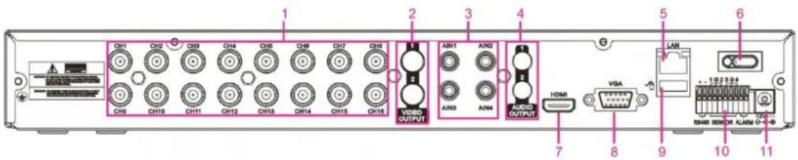
text_image
CH1 CH2 CH3 CH4 CH5 CH6 CH7 CH8 CH9 CH10 CH11 CH12 CH13 CH14 CH15 CH16 1 2 3 4 VISBO OUTPUT AIN1 AIN2 AIN3 AIN4 AUDIO OUTPUT HDMI VGA LAN 1:2:3:2:4 NAMM SENSOR ALAM| Item | Physical port Connection method | |
| 1 | Video input | Connect CH1-16 (Virtual) video input ( BNC interface ) |
| 2 | Video output Connect monitor output(BNC interface) | |
| 3 | Audio input Connect CH1-4 audio signal input (BNC interface) | |
| 4 | Audio output | 2CH output; BNC (interface ) |
| 5 | Ethernet: Port Connect LAN, Ethernet (RJ45 interface) | |
| 6 | Power Switch Turn Power on and off | |
| 7 | HDMI HDMI Output | |
| 8 | VGA Port Connect to VGA monitor, such as PC monitor | |
| 9 | USB Port Connect USB mouse | |
| 10 | RS-485/Sensor/Alarm | RS485/Sensor/Alarm interface (see pin outs below) |
| 11 | Power Port Connect power supply - DC12V 5A | |
2.2.7、16CH-D1 DVR Back Panel
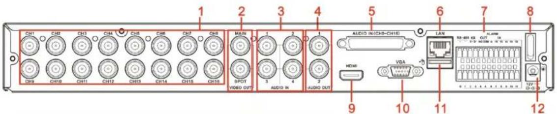
text_image
CH1 CH2 CH3 CH4 CH5 CH6 CH7 CH8 MAIN 1 2 3 4 5 6 7 8 CH9 CH10 CH11 CH12 CH13 CH14 CH15 CH16 SPOT VIDEO OUT AUDIO IN AUDIO OUT AUDIO IN(CHS-CH16) LAN 55-88 GB OUT HDMI VGA 10 11 12 VIA 9 10 11 12| Item | Physical port Connection method |
| 1 | Video input Connect CH1-16 (Virtual) video input ( BNC interface ) |
| 2 | Video output (UP) Main video output; (Down) Spot output (BNC interface) |
| 3 | Audio input Connect CH1-4 audio signal input (BNC interface) |
| 4 | Audio Output 2CH output; RCA(interface ) |
| 5 | Audio input Connect (CH5~CH16) Audio input |
| 6 | Ethernet: Port Connect LAN, Ethernet (RJ45 interface) |
| 7 | RS-485/Sensor/Alarm RS485/Sensor/Alarm interface (see pin outs below) |
| 8 | Power Switch Turn Power on and off |
| 9 | HDMI HDMI Output |
| 10 | VGA Port Connect to VGA monitor, such as PC monitor |
| 11 | USB Port Connect USB mouse |
| 12 | Power Port Connect power supply - DC12V 5A |
2.2.8、16CH(33)-CIF DVR Back Panel
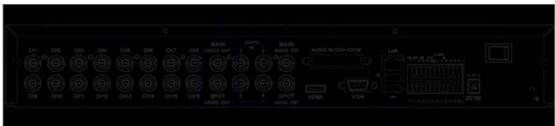
text_image
DH1 CH2 CH3 CH4 CH5 CH6 CH7 CH8 MAIN VIDEO OUT AUDIO CH8 CH10 CH11 CH12 CH13 CH14 CH15 CH16 SPOT 3 SPOT VIDEO OUT AUDIO OUT HDMI VGA LAN DC-12V| Item | Physical port Connection method | |
| 1 | Video input | Connect CH1-16 (Virtual) video input ( BNC interface ) |
| 2 | Video output | (UP) Main video output; (Down) Spot output (BNC interface) |
| 3 | Audio input Connect CH1-4 audio signal input (BNC interface) | |
| 4 | Audio output Connect | audio signal output, including spot main audio output and sequence audio output (BNC interface) |
| 5 | Audio input Connect (CH5~CH16) Audio input | |
| 6 | Ethernet: Port Connect LAN, Ethernet (RJ45 interface) | |
| 7 | Power Switch Turn Power on and off | |
| 8 | HDMI HDMI Output | |
| 9 | VGA Port Connect to VGA monitor, such as PC monitor | |
| 10 | USB Port Connect USB mouse | |
| 11 | USB Port | Connect USB device (Flash Drive, Hard Drive and Recorder etc) |
| 12 | RS-485/Sensor/Alarm | RS485/Sensor/Alarm interface (see pin outs below) |
| 13 | Power Port Connect power supply - DC12V 5A | |
2.2.9、16CH(2U)-CIF DVR Back Panel
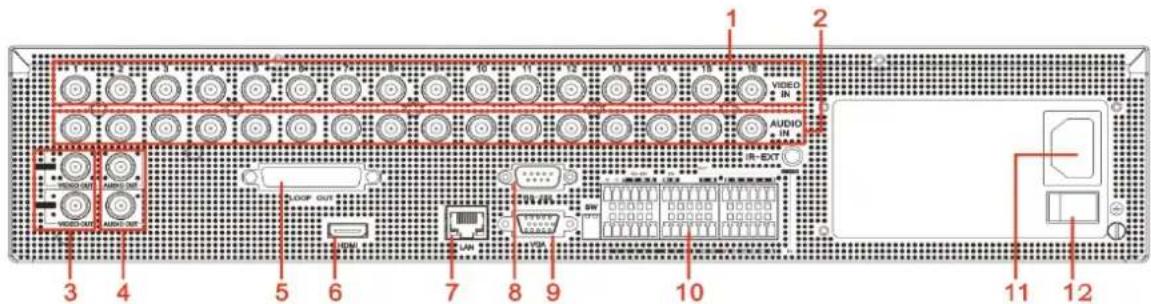
text_image
1 2 AUDIO IN IN-EXT 3 4 5 6 7 8 9 10 11 12| Item | Physical port Connection method | |
| 1 | Video input | Connect CH1-16 (Virtual) video input ( BNC interface ) |
| 2 | Audio input | Connect CH1-16 (Virtual) audio input ( BNC interface ) |
| 3 | Video output Connect monitor output(BNC interface) | |
| 4 | Audio output | Audio input (BNC interface ) |
| 5 | LOOP output | LOOP Output |
| 6 HDMI HDMI Output | ||
| 7 | Ethernet: Port Connect LAN, Ethernet (RJ45 interface) | |
| 8 RS-232 RS-232 Output | ||
| 9 | VGA Port Connect to VGA monitor, such as PC monitor | |
| 10 | RS-485/Sensor/Alarm | RS485/Sensor/Alarm interface (see pin outs below) |
| 11 | Power Port Connect Power | |
| 12 | Power Switch | Turn Power on and off |
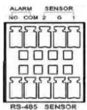
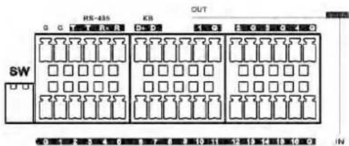
RS485/Sensor/Alarm port functions:
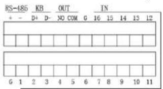
text_image
RS-186 KB OUT IN + - D+ D- NO COM 0 16 15 14 13 12 G 1 2 3 4 5 6 7 8 9 10 11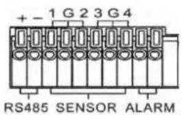
text_image
+ - 1 G 2 3 G 4 RS485 SENSOR ALARM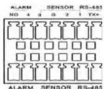
text_image
HS-485 KB OUT G G T R U S P Q K L Q F E E E E E E SW I O I O I O I O I O I O I O I O I O I O I O I O I O I O I O I O I O I O I O I O I O I O I O I O I O I O I O I O I O I O I O I O I O I O I O I O I O I O I O I O I O I O I O I O I O I O I O I O I O I O I O O B C D E F G H I J K L M N N O P Q R S T U V W X Y ZAlarm input: Connect [-] port of your sensor to G (GND) pin, and [+] port to channel input according to the alarm device you purchased.
Alarm output: Connect to the two ports marked with "out"
PTZ Port : Connect your camera to RS-485A and RS485B accordingly.
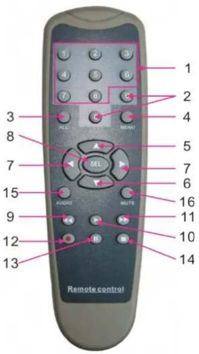
2.3 4/8-CH Remote Controller
text_image
1 2 3 4 5 6 7 8 9 10 11 12 13 14 15 AUDIO MUTE 16 17 18 19 20 21 22 23 24 25 26 27 28 29 30 31 32 33 34 35 36 37 38 39 40 41 42 43 44 45 46 47 48 49 50 51 52 53 54 55 56 57 58 59 60 61 62 63 64 65 66 67 68 69 70 71 72 73 74 75 76 77 78 79 80 81 82 83 84 85 86 87 88 89 90 91 92 93 94 95 96 97 98 99 Remote control| Item | Key title | Key function |
| 1 1-8 | Channel select 1-8; Numeric key | |
| 2 | 9、0 | Numeric key; Clicking numeric “0” allow you switch to GUI (Graphical user Interface) function |
| 3 ALL Multiple display mode | ||
| 4 Menu Enter into Main menu/Exit | ||
| 5 ▲ | Up arrow key, Volume adjust | |
| 6 ▼ | Down arrow key, Volume adjust | |
| 7 |  | Left/Down key,Decrease/increase parameter value of control bar |
| 8 | [SY70Z] | Select key/Edit key;Confirm the selected operation. |
| 9 | [2H3D] | Rewind key |
| 10 | [H0H6] | Enter into record search menu;Play key |
| 11 | [3208] | Forward key |
| 12 |  | Record key |
| 13 | [X008] | Pause/Sequence key |
| 14 |  | Stop manual record; stop playing |
15 Audio  | ||
16 Mute  | ||
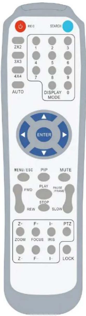
2.4 16-CH Remote Controller
text_image
REC SEARCH 2X2 1 2 3 3X3 4 5 6 4X4 7 8 9 AUTO DISPLAY MODE 0 ENTER MENU/ESC PIP MUTE FWD PLAY PAUSE FRAME STOP REW SLOW Z+ F+ I+ PTZ ZOOM FOCUS IRIS Z- F- I- LOCK| Key Title | Key Function |
| REC Press the button to enter into manual record. | |
| SEARCH Press the button to enter into record search menu | |
| 2×2 | Enter into Quad display |
| 3×3 | Enter into 9-split display |
| 4×4 | Enter into 16-split display |
| AUTO Enter into dwell time display | |
| 0~9 Channel select; numeric key | |
| DISPLAY MODE | Multiple CH display (Quad, 9-split, 16-split and full screen display) |
| ▲ | Up direction key |
| ▼ Down direction key | |
| ◄/► | Left/right direction key; also decrease/increase parameter value of control bar. |
| ENTER select [Enter] / [Edit] operation | |
| Menu/ESC Enter into/exit Main menu | |
| PIP PIP display mode | |
| MUTE Mute key | |
| FWD | Forward ( x2、x4、x8 ) |
| REW | Rewind ( x2、x4、x8 ) |
| PLAY Enter into record search, play record event | |
| STOP Stop play / manual play | |
| PAUSE/FRAME | Pause / play frame by frame |
| SLOW | ( 1/2、1/4、1/8 ) Slow play |
| Z+ Zoom out video area | |
| Z- Zoom in video area | |
| F+ Extend focus | |
| F- Extend focus | |
| I+ Increase PTZ brightness | |
| I- Decrease PTZ brightness | |
| PTZ Allow you set preset bit and control PTZ. | |
| LOCK Lock system | |
Mouse Operation
Except using buttons of front panel or remote controller, you also can use mouse to perform system operation.
| TYPE Function | |
| Click left key of Mouse | In menu lock mode, Enter into pop-up menu and clicking any sub menu to pop up Log-in window; on menu unlock mode, enter into pop-up menu, and then clicking left key to enter into any sub menu directly. |
| After entering into main menu, clicking left key could enter into any sub menu; On [Detailed file] menu mode, clicking left key could playback one recording file. | |
| Change the status of check box and motion detection area. | |
| Clicking combo box to access pull-down menu; Click left key to stop dwell time display when dwell time display is activated. | |
| By clicking left key you can adjust Color control bar and volume control bar. | |
| Clicking combo box to access pull-down menu | |
| By clicking left key you can select values in edit boxes or pull-down menu and supports Chinese word input, special symbol, numeric and character input, use instead of [Enter- ] or [Backspace ] | |
| Click right key of Mouse | In live display mode, clicking right key will display pop-up menu (shown as Picture 5-1). |
| In Main menu or sub menu mode, clicking right key will exit current menu. | |
| Double-click Left key of Mouse | In live display or playback mode, double-clicking left key will maximize the screen. |
| Moving Mouse Select menu item | |
| Sliding Mouse On | motion mode, sliding mouse will select motion area; On [Color set] menu mode, sliding mouse will adjust color control bar and volume control bar. |
Chapter 3 DVR INSTALLATION
3.1 HDD Installation (Applicable to the model with HDD drawer)
Caution : Please do not Install or take out hard drive when DVR is running!
(1) The model has a HDD drawer. Please use provided key to take out the HDD drawer and put HDD into the drawer correctly.
(2) Cut power firstly, and then remove screws and open DVR upper cover carefully;
(3) Insert Power Cord and data cable into Pin of hard drive securely;
(4) Remove the screws on the HDD bracket; fix the HDD to the bracket and then fix the bracket with HDD to DVR body
(5) Put the upper cover back carefully, re-attach screws.
Note: If user requires higher performance HDD, strongly recommend you use special hard driver for security and protection
3.2 Camera and Monitor Connection
Connect camera cable to video input of DVR, and from video output of DVR to Monitor via BNC connector (Refer to section2.2-Rear Panel); or
If the camera is a PTZ speed dome, you could connect RS485 A & B to the according port of DVR respectively (refer to system figuration on Chapter 8).
3.3 Power Supply connection
Please only use the power adapter supplied with the DVR.
After power on please make sure the video I/O connection well, audio device with RCA cable.
Chapter 4: DVR Boot up
4.1 System Initialization
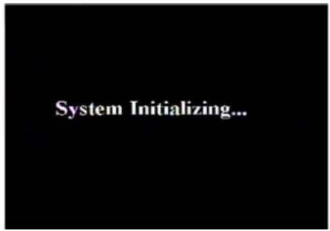
text_image
System Initializing...Picture 4-1
After connecting the Power cable of DVR to wall outlet and pressing the Power button on the front panel, you will enter into the system initializing screen shown as Picture 4-1
4.2 Live Interface
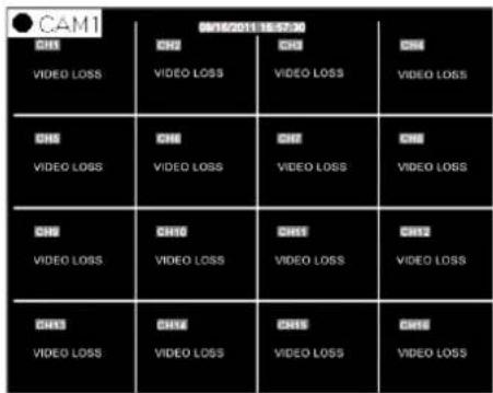
After finishing initialization the system will enter into
area outside the menu allows you exit the Pop-up menu.
Note: When internal HDD is not connected or an error occurs, the character "H" will appear on the first channel of the live screen and accompany buzzer alarm. If you want to close the buzzer alarm, please enter into [Main menu→Alarm] to set HDD loss, HDD space not enough and alarm output to "off"
Chapter 5: DVR Menu
5.1 Pop-up Menu
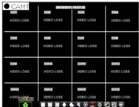
text_image
CAM1 CHS VIDEO LOSS CHS VIDEO LOSS CHS VIDEO LOSS CHS VIDEO LOSS CHS VIDEO LOSS CHS VIDEO LOSS CHS VIDEO LOSS CHS VIDEO LOSS CHS VIDEO LOSS CHS VIDEO LOSS CHS VIDEO LOSS CHS VIDEO LOSS CHS VIDEO LOSS CHS VIDEO LOSSPicture 5-1
After finishing system initialization, click right key of mouse on main interface mode to enter into Pop-up Menu. Now you could perform parameter setting and operate on Main Menu, Multi-Pics, PTZ, PIP, Rec. Search, Mute, Manual record, Start Rolling, Start Cruise and Vo Switch etc.
Clicking [0] key on the remote controller or holding press [Esc] key on the front panel could switch system to other output device.
5.2 Main Menu Guide
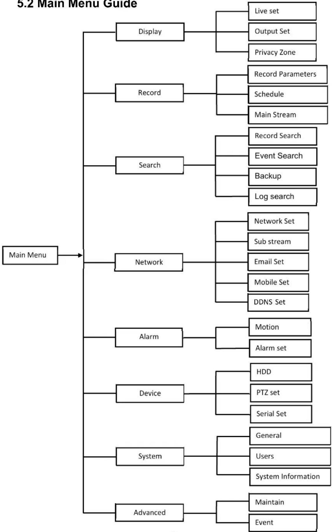
flowchart
graph TD
    A["Main Menu"] --> B["Display"]
    A --> C["Record"]
    A --> D["Search"]
    A --> E["Network"]
    A --> F["Alarm"]
    A --> G["Device"]
    A --> H["System"]
    A --> I["Advanced"]

    B --> J["Live set"]
    B --> K["Output Set"]
    B --> L["Privacy Zone"]

    C --> M["Record Parameters"]
    C --> N["Schedule"]
    C --> O["Main Stream"]

    D --> P["Record Search"]
    D --> Q["Event Search"]
    D --> R["Backup"]
    D --> S["Log search"]

    E --> T["Network Set"]
    E --> U["Sub stream"]
    E --> V["Email Set"]
    E --> W["Mobile Set"]
    E --> X["DDNS Set"]

    F --> Y["Motion"]
    F --> Z["Alarm set"]

    G --> AA["HDD"]
    G --> AB["PTZ set"]
    G --> AC["Serial Set"]

    H --> AD["General"]
    H --> AE["Users"]
    H --> AF["System Information"]

    I --> AG["Maintain"]
    I --> AH["Event"]
5.3 Main Menu
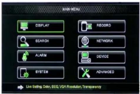
text_image
MAIN MENU DISPLAY RECORD SEARCH NETWORK ALARM DEVICE SYSTEM ADVANCED Live Setting, Color, SEQ, VDA Resolution, TransparencyPicture 5-2
On
5.3.1 Display
5.3.1.1 Live mode
Go to
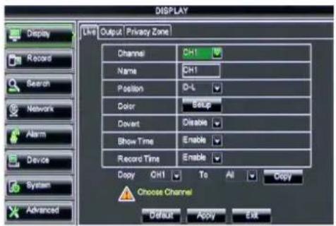
text_image
DISPLAY Live Output Privacy Zone Channel CH1 Name CH1 Position D-L Color Setup Dewert Disperse Show Time Enable Record Time Enable Copy CH1 To Alt Copy Choose Channel Default Apply ExitPicture 5-3
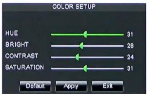
text_image
COLOR SETUP HUE 31 BRIGHT 28 CONTRAST 24 SATURATION 31 Default Apply ExitPicture 5-4
Channel: allow you setup the channel you desired.
Name: allow you setup the channel name, and system support up to eight characters or four Chinese characters.
➢ Position: allow you setup the display position of each channel.
Color: Click [Setup] option to enter into the [Color setup] interface shown as Picture 5-4.
➢ Covert: allow you enable [Live] surveillance screen
Show time: allow you enable system time appear in the
Record time: When set to "Enable", you are allowed to record system time into the record history.
Copy: allow you copy all data of one channel to any other one
Above picture 5-4 is the Color Menu where you can adjust image brightness, saturation, contrast and hue parameters of each channel.
Explanation :
1、The modifications will be available after clicking [APPLY] button on the bottom of the sub-menu windows and being prompted to save and then clicking [ok] button.
2、If you want to cancel the modification, click [Exit] button to exit the menu.
3、When clicking [DEFAULT] button, all system default values will be reset to default value.
4、System default value indicates the value pre-set at the factory.
5.3.1.2 Output mode
Go to [Main menu→Display→Output] to enter into the output set interface shown as Picture 5-5.
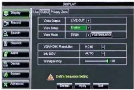
text_image
DISPLAY Live Output Privacy Zone Video Output LIVE-OUT View Setup Enable View Mode Single Your Sequence VGA/HDMI Resolution HDMI Init DEV AUTO Transparency 128 Define Sequence Setting Default Apply ExitPicture 5-5
Click [Spot output] option and set relative parameters shown as Picture 5-7.
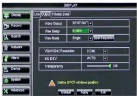
text_image
DISPLAY Live OUTPUT Privacy Zone Video Output SPOT-OUT View Setup E-M4 View Mode Single SPOA Sequence VGA/HDMI Resolution HDMI Int. DEV AUTO Transparency 128 Define SPOT windows position Default Apply ExitPicture 5-7
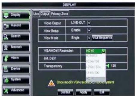
text_image
DISPLAY Display Live Output Privacy Zone Record View Setup Enable View Mode Single Your Sequence VGA/HDMI Resolution HDMI Init. DEV 0246/704 Transparency 4296/704 128 Once modify VGA resolution in door systems Default Apply EditPicture 5-9
Click [Live] to pop up the interface shown as Picture 5-6. Now you could perform channel sequence setting.
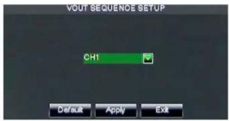
text_image
VOUT SEQUENCE SETUP CH1 Default Apply ExitPicture 5-6
Click [Spot sequence] to enter into the interface shown as Picture 5-8.
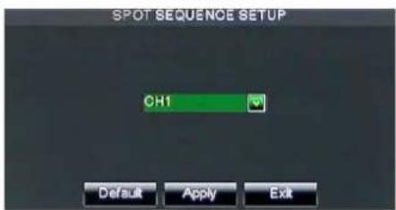
text_image
SPOT SEQUENCE SETUP OH1 Default Apply ExitPicture 5-8
Video output: Support CVBS output Live and Spot mode simultaneously, and Live is main output, and Spot is auxiliary output.
CH Sequence: the option is defaulted to "Off" and sequence time is 5 second. User can activate the option as per request.
Rotate time: allow you set sequence time, and minimum time can be set to 3 seconds.
VGA/HDMI Resolution: allow you select VGA or HDMI output, including 800x600, 1024x768, 1280x1024, 1440x900 and HDMI.
➢ Display Mode:
Live output: display window will include Single, Quad, 9-split and 16-split mode; Spot output: display window will include Single, Quad and 9-split mode.
Transparency: allow you adjust menu's transparency, and its range is 1\~128.
Margin: allow you adjust the whole screen's margin. Details operations please refer to the Picture 5-10.
Volume: allow you adjust the DVR volume shown as Picture 5-11.
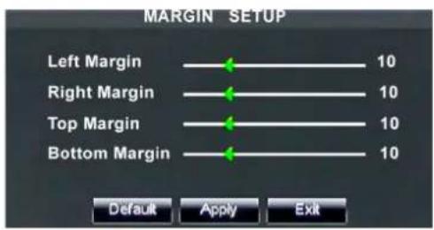
text_image
MARGIN SETUP Left Margin 10 Right Margin 10 Top Margin 10 Bottom Margin 10 Default Apply ExitPicture 5-10

Picture 5-11
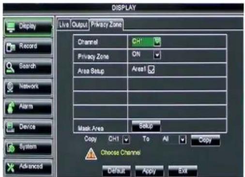
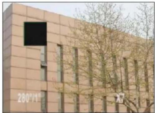
The function Allow you setup privacy zone parameters according to Picture 5-12. Each channel could set up to four privacy zones, and please follow below steps to set:
- Select the area no (Area 1 \~ Area 4);
- Click [Setup] to adjust position of mask area;
- After finishing position adjust, click right key of mouse to return back [Privacy zone] interface;
- Click [Apply] to save the above setting.
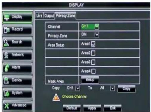
text_image
DISPLAY Live Output Privacy Zone Channel CH1 Privacy Zone ON Area Setup Area1 Areas2 Areas3 Areas4 Mask Area Setup Copy CH1 To All Copy Choose Channel Default Apply ExitPicture 5-12
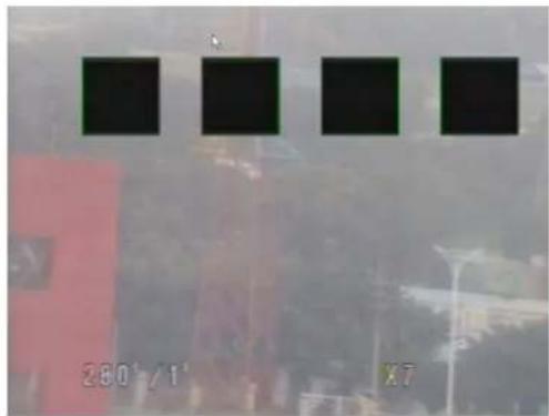
text_image
280°/1' X7Picture 5-13
text_image
DISPLAY Live Output Privacy Zone Channel CH1 Privacy Zone ON Area Setup Area1 Mask Area Setup Copy CH1 To All Copy Choose Channel Default Apply Exit5.3.2 Record set
natural_image
Exterior view of a modern building with visible window grilles and tree branches (no signage or text)This figure is only for D9016 / CIF model reference
5.3.2.1 Record parameters
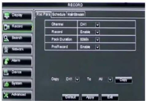
Go to [Main menu→Record→Record Para] to enter into the interface shown as Picture 5-14.
text_image
RECORD Display Record Search Networks Alarm Device System Advanced Rec Para Schedule MainStream Channel CH1 Record Enable Pack Duration 80Min PreRecord Enable Copy CH1 To All Copy Default Apply ExitPicture 5-14
➢ Channel: allow you setup the channel you desired.
Record: allows you set up record status (Enable/Disable) of each channel
Pre-record: Motion detection and I/O triggered record support Pre-record function.
5.3.2.2 Schedule
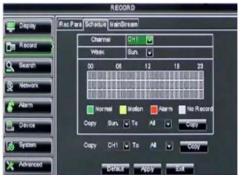
Click [Main Menu→Record→Schedule] to enter into the interface shown as Picture 5-15.
text_image
RECORD Display Record Search Network Alarm Device System Advanced Rec Para Schedule MainStream Channel CH1 Week Sun 00 08 12 18 23 Normal Motion Alarm No Record Copy Sun To All Copy Copy CH1 To All Copy Default Apply ExitPicture 5-15
[Channel] option allows you select one channel you desired.
To setup weekly schedules, tick-select the box of the record status you want (Alarm, General, or No Record) and then click on each box in the schedule time line that you want this method to apply to. You can use the [Copy - To] pull-down menus and Copy button to copy settings from one day to another day or all days.
After you complete the schedule you activate it by clicking the [Apply] button.
You can also click on the Default button to use the system defaults.
Explanation: Under the
5.3.2.3 Main Stream
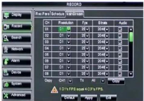
Go to [Main menu→Record→Main Stream] to enter into the interface shown as Picture 5-16.
text_image
RECORD Display Record Search Network Alarm Device System Advanced Rec Para | Schedule | MainStream CH Resolution Fps Strata Audio 01 D1 25 2046 02 D1 25 2046 03 D1 25 2046 04 D1 25 2046 05 D1 25 2046 06 D1 25 2046 07 D1 25 2046 08 D1 25 2046 Copy CH1 To All Copy 1.01's FPS equal 4 CIF's FPS. Default Apply ExitPicture 5-16
➢ Resolution: support D1, HD1 and CIF.
Frame rate: PAL: 1-25 f/s ; NTSC: 1-30 f/s.
Bit rate: user could select the relative value by pull-down menu.
Audio: When tick-selecting the option, system will record video stream with audio simultaneously
5.3.3 Search
5.3.3.1 Record Search
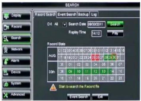
Click [Main Menu→Search→Record Search] to enter into the interface shown as Picture 5-17.
text_image
SEARCH Record Search Event Search Backup Log CH All Search Date 09/02/2011 Search Replay Time 14:12 Play Record State AUG 07 02 03 04 05 06 07 08 09 10 11 12 13 14 15 16 17 18 19 20 21 22 23 24 25 26 27 28 29 30 31 30m 36 37 38 39 40 41 42 43 44 45 46 47 Start to search the Record file Event Search ExitPicture 5-17
Channel: allows you select the channel(s) you desire to search.
Date Search: In the Video Search screen, user can search for all the records in a specific date. To execute a video search, highlight and select the date numeric field, and then click a detailed time quantum of the specific date, system will start the playback from the first record of the time quantum.
Time Search: In the
File List: click [File List] button to enter into the [Event Search] screen shown as Picture 5-19, the video records for the time quantum will appear in the screen.
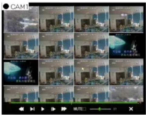
Playback Mode: You can use the Playback Control bar to operate the Fast Forward (X2, X4 and X8), Slow play (1/2, 1/4 and 1/8 speed), Play, Pause/Frame, Rewind(X2, X4 and X8). When ending playback, DVR will return back to previous menu shown as Picture 5-20.
Play control Bar: the play control bar will display current playing processing shown as Picture 5-20. When user click any time at the control bar and this point have not any record file, system will auto return back to previous menu.
5.3.3.2 Channel Select
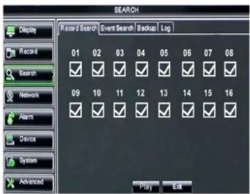
Click [Main Menu→Search→Record search] to enter into the interface shown as Picture 5-18
Then tick-select the channel you want to playback; and click [Play] button to enter into the playback mode shown as Picture 5-19
text_image
SEARCH Record Search Event Search Backup Log 01 02 03 04 05 06 07 08 ✓ ✓ ✓ ✓ ✓ ✓ ✓ ✓ ✓ 09 10 11 12 13 14 15 16 ✓ ✓ ✓ ✓ ✓ ✓ ✓ ✓ ✓ Play EditPicture 5-18
text_image
CAM1 20:10 MUTEPicture 5-19
5.3.3.3 Event Search
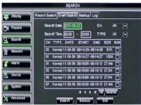
Click [Main Menu→Search→Event Search] to enter into the interface shown as Picture 5-20.
You could highlight and double-click the desired record for playback. And you also can filter the records you want to view based on date, time, and channel and record mode search.
text_image
SEARCH Record Search Event Search Backup Log Search Date 231-08-37 Ch: All Search Time 00:00 - 23:59 TYPE: All CH TYPE DATE START END SIZE BAK 02 Normal 11-08-30 09:14:28~09:14:28 87K 01 Normal 11-08-30 09:14:37~09:14:27 102K 01 Normal 11-08-30 09:18:55~09:19:10 27.4M 03 Normal 11-08-30 09:18:55~09:19:10 27.3M 06 Normal 11-08-30 09:18:55~09:19:10 27.6M 07 Normal 11-08-30 09:18:55~09:19:10 27.4M M K M 23 Reverse Search BACKUP EXPicture 5-20
(First Page): go to the first page on the list. When you view other pages, clicking [First] button brings you back to Page one.
(Previous page): go to the previous ones of current page. Clicking [Pre] button will take you back the previous ones of current page (except the first page).
☑(Next page): go to the next ones of current page. Clicking the [Next] button will take you to the next ones of current page (except the last page)
(Last page): go to the last page. Clicking the [last] button will make you enter into last page quickly.
ALL (Select All): Allows you to select all the events on the current page.
Inverse (Select Invert): Allows you to select other events on the current page except those you have currently selected.
5.3.3.4 File Backup
You can back-up the record files based on event or time.
5.3.3.4.1 back-up file based on event
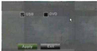
In the [File List] mode, if you wish to backup records, please tick-select the BAK check-boxes which correspond to the records and click [Backup] button to enter into the below windows illustrated in Picture 5-21
In the [File List] mode, if you wish to backup records, please tick-select the BAK check-boxes which correspond to the records and click [Backup] button to enter into the below windows illustrated in Picture 5-21
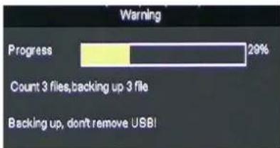
Select USB as backup device and click [Apply] button, and then enter into the window shown as Picture 5-22.
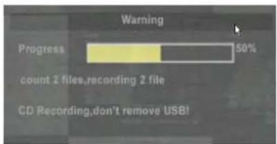
Select DVD as backup device and click [Apply] button, and then enter into the window shown as Picture 5-23.
text_image
USB DVD Apply ExitPicture 5-21
bar
| Status | Percentage | | ------ | ---------- | | Progress | 29% | | Count 3 files, backing up 3 file | - | | Backing up, don't remove USBI | - |Picture 5-22
text_image
Warning Progress 50% count 2 files,recording 2 file CD Recording,don't remove USB!Picture 5-23
text_image
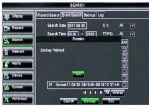
SEARCH Record Search Event Search Backup Log Search Date 2011-08-30 CH: All Search Time 00:00 - 2:59 TYPE: All Remark Backup finished OK 07 Normal 11-08-30 09:18:55-09:19:10 27.4M Search Backup ExitPicture 5-24
After backup finished, please click [OK] button shown as Picture 5-24.
Note:
● File will be saved as *.264 format.
- You could playback the record files via Dvr Client player. When installing Dvreclient, system will auto install the player.
- Please make sure the back-up device connect well before backup.
5.3.3.4.2 back-up file based on time
Also allow you back-up record files based on time. Please follow below steps to back up these files (Details operations please refer to section 5.3.4.4.1.):
- input start time and end time on the time edit box;
- Click [Search] button;
- Tick-select all the files you desire to backup;
- Click the [Backup] on the bottom.
5.3.3.4.3 Media Player backup
-
Copy one backup file to your PC.
-
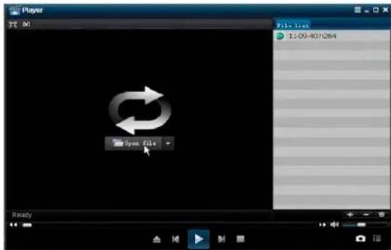
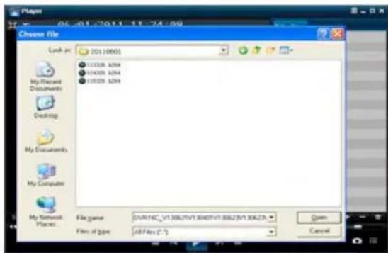
Open Playback player and click "+" icon or file, and then click [open] button.

button to find/select the backup
- Highlight the file you have selected and click [Play] button.
text_image
Player File Line 1:09-407264 Open file ReadyPicture 5-25
text_image
06-01-2011 11:24:09 Choose file Lock-in: 00110600 My Documents Documents Desktop My Documents My Computer My Network Explorer File name: OVR14C_V1 30K27V1 30407-V1 30K23V1 30K23 Files of type: JPEG files (*.*)Picture 5-26

: Play button: click the icon to playback the backup record;

: Pause button: click the icon to pause the backup record;

: Stop button: click the icon to stop the backup record;

: Next: Click the icon to play next record;

: Prev.: Click the icon to play previous record
: Slow button: click the icon to play the backup record at 1/2, 1/4, 1/8 and 1/16 speed.
FF button: click the icon to fast forward the backup record at x2, x4, x8 and/or x16
speed.

Open: click the icon to open one record file.

click the icon to enter into full screen mode.

: Click the icon to never place one target to top.

: Click the icon to place one target to top.

: Click the icon to place the playing record to top.

: Snapshot button: click the icon to capture the live image and save the captured one to dictory:\video client\capture.
: Volume Adjust: click the icon to adjust the volume.

: Add fold or file to player.

Delete one file in the list

Delete all the files in the list

: Unfold or fold the list files

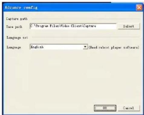
: Advance Configuration: click the icon to set capture path and language shown as Picture 5-27.
text_image
Advance config Capture path Save path C:\Program Files\Video Client\Capture Select Language set Language English Need relevant player software) OK CancelPicture 5-27
5.3.3.5 Log Search
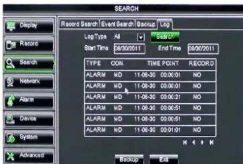
Go to [Main menu→Search→Log] option to enter into the Log search interface shown as Picture 5-28.
text_image
SEARCH Record Search | Event Search | Backup | Log Log Type All Search 09/02/2011 End Time 09/02/2011 Start Time 08/02/2011 TYPE CON TIME POINT RECORD ALARM MD 11-08-30 00:06:01 NO ALARM MD 11-08-30 00:06:01 NO ALARM MD 11-08-30 00:06:21 NO ALARM MD 11-08-30 00:06:51 NO ALARM MD 11-08-30 00:06:51 NO ALARM MD 11-08-30 00:01:01 NO Backup ExitPicture 5-28
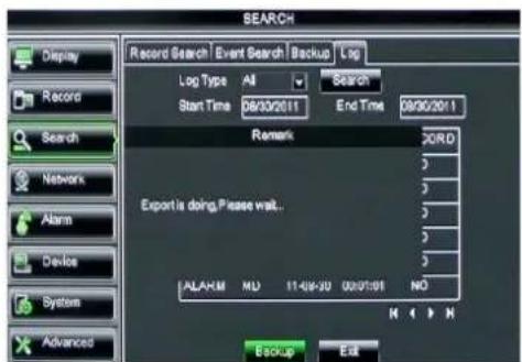
Herein allow you preview the log information you have searched. And click [Backup] to export all the log information which is listed. For other button functions please refer to previous section 5.3.3.3-Event Search
text_image
SEARCH Record Search Event Search Backup Log Log Type All Search Start Time 09/30/2011 End Time 09/30/2011 Remark Export is doing.Please wait... ALARM NO 11-09-20 00:01:08 NO Backup ExitPicture 5-29
5.3.4 Network
5.3.4.1 Network set
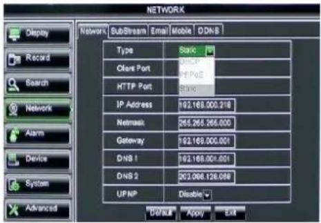
Click [Main menu→Network→Network] to enter into the below interface shown as Picture 5-30.
text_image
NETWORK Display Record Search Network Alarm Device System Advanced Network SubStream Email Mobile D:DNS Type Static Client Port DHCP HTTP Port IP Address 192.168.000.218 Netmask 264.265.266.000 Gateway 192.168.000.001 DNS 1 192.168.001.001 DNS 2 202.006.128.099 UPNP Disable DEFAULT Apply ExitPicture 5-30
After selecting network mode - such as DHCP, PPPOE or static allocation- and setting up web ports, you can visit DVR remotely through a network or internet.
UPnP (Universal Plug and Play) function: If router supports UPnP function and set
DNS: DNS server is generally provided by local ISP. Herein please enter the IP address of your DNS
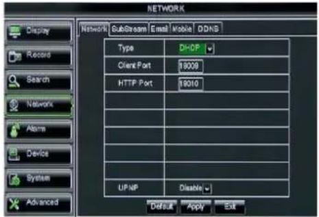
text_image
NETWORK Display Record Search Network Alarms Device System Advanced Network SubStream Email Mobile DDNS Type DI-DP Client Port 19008 HTTP Port 19010 UP MP Disable Default Apply ExitPicture 5-31
When selecting DHCP from the Type, A router will automatically allocate IP address for your DVR. After restarting each time, the IP address captured by your DVR may be different. So, port forwarding is required when you visit a remote DVR.
- Select DHCP and click [Save] button;
- Exit and restart DVR;
- Input media port and web port
4 Set IP address captured by DVR and web port to a router
5 Visit a remote DVR
http://public net IP: web port (such as: 8080)
http://intranet IP: web port (such as: 8080 - only use for Intranet)
6 Input the IP address of your domain name server
Friendly Reminder:
- All the parameters you set are available only when you click [Apply] and after system are restarted.
- User need to change MAC address when there are multiple DVRs at the same local area network. Details please refer to section 5.6.2.5 -System Information.
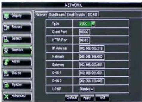
text_image
NETWORK Display Record Search Network Alarm Device System Advanced Network SubStream Email Mobile DDNS Type Static Client Port 19009 HTTP Port 16310 IP Address 192.168.000.218 Netmask 265.265.265.000 Gateway 192.168.000.001 DNS 1 192.168.001.001 DNS 2 202.098.128.088 UP NP Disable√ Default Apply ExitPicture 5-32
When selecting Static from the Type, user can directly input IP address, Subnet Mask, Gateway and DNS shown as below picture 5-33.
- Set your net type to Static;
- Set media port number (such as 9000), and the port need to be forwarded to a router.
-
Input web port number (such as 8080), and the port need to be forwarded to a router;
-
Input a specified IP address to [IP address] column;
-
The Subnet Mask, gateway and DNS server should be consistent with your router's configurations.
- Input DNS address. Please check router firstly. The setting should be consistent with router's
- Click [Apply] button
- Now you could remotely visit the DVR via IP
http://public net IP: web port (such as: 8080)
http://intranet IP: web port (such as: 8080 - only use for Intranet)
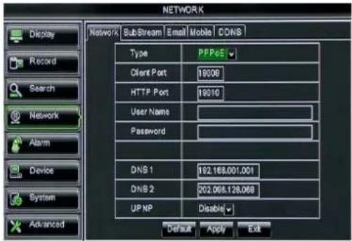
text_image
NETWORK Display Record Search Network Alarm Device System Advanced Network SubStream Email Mobile CDNS Type PPPoE Client Port 19006 HTTP Port 19010 User Name Password DNS 1 192.168.001.001 DNS 2 202.095.128.068 UP NP Disable Default Apply ExitPicture 5-33
When selecting PPPoE form the Type, user can input user name and password provided by ISP and set Media and Web port. And now you can visit your remote DVR by using the IP address captured after registering a domain name and web port and connect to your DVR via public network.
5.3.4.2 Router's Port Forwarding
Port forwarding is required when you want to access the DVR connected to the router from outside of the router's network.
If PPPoE is selected, port forwarding is not required.
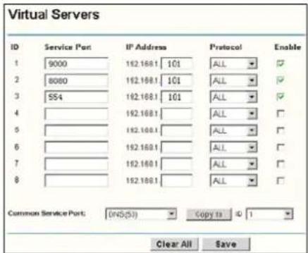
text_image
Virtual Servers ID Service Port IP Address Protocol Enable 1 9000 162.168.1 101 ALL ✓ 2 8080 162.168.1 101 ALL ✓ 3 554 162.168.1 101 ALL ✓ 4 5 6 7 8 Common Service Port: (INS(S)) Copy to 1 Clear All SavePicture 5-34
- Input router's IP address from IE-based browser to open the Router configuration interface shown as Picture 5-36;
- Click [Transmittal rule] option to take you to the port forwarding instructions for your router;
- The DVR IP address for the intranet should be <192.168.1.101>, you should forward server port and web port to this IP address respectively.
- Now user can visit the DVR remotely.
Friendly Reminder: The router's port forwarding interface may be different, however, when entering into virtual server, user will always need forward port (range: 1025\~65535) of router to IP address of DVR allocated or automatically captured, and select [All] or [Both] in corresponding protocol column and save the above setting.
Above steps may differ from the router device depending on the manufacturer.
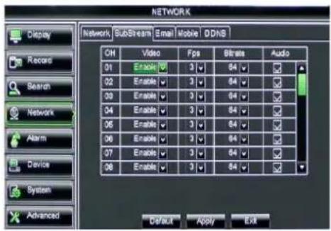
5.3.4.3 Sub stream
Go to [Main menu→Network→Sub Stream] to enter into the interface shown as Picture 5-35
text_image
NETWORK Network SubStream Email Mobile ODNS CH Video Fps Bit rate Audio 01 Enable 3 84 K 02 Enable 3 84 K 03 Enable 3 84 K 04 Enable 3 84 K 05 Enable 3 84 K 06 Enable 3 84 K 07 Enable 3 84 K 08 Enable 3 84 K Default Apply ExitPicture 5-35
➢ Audio: When tick-selecting the option
Video: allow you open or close the sub stream output. If you select "Enable" system will select sub-stream preview and guarantee image quality once network is unstable.
Frame rate: allow you set net transmittal frame rate. User could select the relative value by pull-down menu.
Bit rate: allow you set net transmittal bit rate. User could select the relative value by pull-down menu.
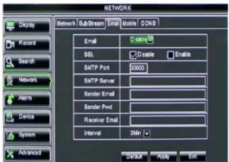
5.3.4.4 Email set
Click [Main Menu→Network→Email] option to enter into the email set interface shown as Picture 5-36
text_image
NETWORK Display Network SubStream Email Mobile DDNS Email Disable SSL Disable Enable SMTP Port 00000 SMTP Server Sender Email Sender Pvd Receiver Email Interval 3Min Default Apply Exit Record Search Network Alarm Device System AdvancedPicture 5-36
SSL: is a security link transport protocol. You can encrypt your communication info (including your email) using SSL to prevent hackers from monitoring your email or communication info and even your password.
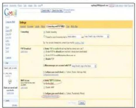
Please set SSL to "On" via Gmail.com server, and set to "Off" via other mail server.
text_image
Gmail Settings Search: 100% User List: New user list Forwarding To: Click Nextday Forwarded as part of the following: For any time (if any time is required) then click To: Find the next day's first time PDFs (which is available only if the last time is required) To: Find the next day's first time after the next time To: Find the next day's first time after the next time To: Find the next day's first time after the next time To: Find the next day's first time after the next time To: Find the next day's first time after the next time To: Find the next day's first time after the next time To: Find the next day's first time after the next time To: Find the next day's first time after the next time To: To: Find the next day's first time after the next time To: Find the next day's first time after the next time To: Find the next day's first time after the next time To: Find the next day's first time after the next time To: Find the next day's first time after the next time To: Find the next day's first time after the next time To: Find the next day's first time after the next time To : Find the next day's first time after the next time To : Find the next day's first time after the next time To : Find the next day's first time after the next time To : Find the next day's first time after the next time To : Find the next day's first time after the next time To : Find the next day's first time after the next time To : Find the next day's first time after the next time To : Find t##e##t## ###### To : Find t##e##t## ###### To : Find t##e##t## ###### To : Find t##e##t## ###### To : Find t##e##t## ###### To : Find t##e##t## ###### To : Find t##e##t## ###### To : Find t##e##t## ###### To : Find t##e##t## ###### To : Find t##e##t## ###### TO : Find t##e##t## ###### TO : Find t##e##t## ###### TO : Find t##e##t## ###### TO : Find t##e##t## ###### TO : Find t##e##t## ###### TO : Find t##e##t## ###### TO : Find t##e##t## ###### TO : Find t##e##t## ###### TO : Find t##e##t## ###### TO: Find t##e##t## ###### TO: Find t##e##t## ###### TO: Find t##e##t## ###### TO: Find t##e##t## ###### TO: Find t##e##t## ###### TO: Find t##e##t## ###### TO: Find t##e##t## ###### TO: Find t##e##t## ###### TO: Find t##e#t# TO: Find t##e#t# TO: Find t##e#t# TO: Find t##e#t# TO: Find t##e#t# TO: Find t##e#t# TO: Find t##e#t# TO: Find t##e#t# TO: Find t##e#t# TO: Find t##e#t# TO: Find t##e#t# TO: Find t##e#t# TOM #100% TOM #100% TOM #100% TOM #100% TOM #100% TOM #100% TOM #100% TOM #100% TOM #100% TOM #100% TOM #100% TOM #100% TOM #100% TOM #100% TOM #100% TOT #100% TOT #100% TOT #100% TOT #100% TOT #100% TOT #100% TOT #100% TOT #100% TOT #100% TOT #100% TOT #100% TOT #100% TOT #100% TOT #100% TOT #256 TOT #256 TOT #256 TOT #256 TOT #256 TOT #256 TOT #256 TOT #256 TOT #256 TOT #256 TOT #256 TOT #256 TOT #256 TOT #256 TOT #256 TGT # TGT # TGT # TGT # TGT # TGT # TGT # TGT # TGT # TGT # TGT # TGT # TGT # TGT # TGT # TGT # TGT # TGT # TGT # TGT # TGT # TGT # TGT # TGT # TGT # TGT # TGT # TGT # TGT # TGT # TGT # TGT # TGT # TGT # SUT SUT SUT SUT SUT SUT SUT SUT SUT SUT SUT SUT SUT SUT SUT SUT SUT SUT SUT SUT SUT SUT SUT SUT SUT SUT SUT SUT SUT SUT SUT SUT SUT SUT MUST. MUST. MUST. MUST. MUST. MUST. MUST. MUST. MUST. MUST. MUST. MUST. MUST. MUST. MUST. MUST. MUST. MUST. MUST. MUST. MUST. MUST. MUST. MUST. MUST. MUST. MUST. MUST. MUST. MUST. MUST. MUST. MUST. MUST. NUT. NUT. NUT. NUT. NUT. NUT. NUT. NUT. NUT. NUT. NUT. NUT. NUT. NUT. NUT. NUT. NUT. NUT. NUT. NUT. NUT. NUT. NUT. NUT. NUT. NUT. NUT. NUT. NUT. NUT. NUT. NUT. NUT. NUT . NUT . NUT . NUT . NUT . NUT . NUT . NUT . NUT . NUT . NUT . NUT . NUT . NUT . NUT . NUT . NUT . NUT . NUT . NUT . NUT . NUT . NUT . NUT . NUT . NUT . NUT . NUT . NUT . NUT . NUT . NUT . NUT . NUT . SOUT . SOUT . SOUT . SOUT . SOUT . SOUT . SOUT . SOUT . SOUT . SOUT . SOUT . SOUT . SOUT . SOUT . SOUT . SOUT . SOUT . SOUT . SOUT . SOUT . SOUT . SOUT . SOUT . SOUT . SOUT . SOUT . SOUT . SOUT . SOUT . SOUT . SOUT . SOUT . SOUT . SOUT .NET . NET . NET . NET . NET . NET . NET . NET . NET . NET . NET . NET . NET . NET . NET . NET . NET . NET . NET . NET . NET . NET . NET . NET . NET . NET . NET . NET . NET . NET .NET . NET .NET . NET .NET . NET .NET . NET .NET . NET .NET . NET .NET . NET .NET . NET .NET . NET .NET . NET .NET . NET .NET . NET .NET . NET .NET . NET .NET . NET .NET . NET .NET . NET .NET . NET .NET . NET .NET . NET .NET . NET .NET . NET .NET . NET .NET . NET .NET . NET. NET .NET .NET .NET .NET .NET .NET .NET .NET .NET .NET .NET .NET .NET .NET .NET .NET .NET .NET .NET .NET .NET .NET .NET .NET .NET .NET .NET .NET .NET .NET .NET .NET .NET .NET .NET .NET .NET .NET .NET .NET .NET .NET .NET .NET .NET .NET .NET .NET .NET .NET .Net .Net .Net .Net .Net .Net .Net .Net .Net .Net .Net .Net .Net .Net .Net .Net .Net .Net .Net .Net .Net .Net .Net .Net .Net .Net .Net .Net .Net .Net .Net .Net .Net .Net .Net .Net .Net .Net .Net .Net .Net .Net .Net .Net .Net .Net .Net .Net .Net .Net .No. NET. NET. NET. NET. NET. NET. NET. NET. NET. NET. NET. NET. NET. NET. NET. NET. NET. NET. NET. NET. NET. NET. NET. NET. NET. NET. NET. NET. NET. NET. NET. NET. NET. NET. NET. NET. NET. NET. NET. NET. NET. NET. NET. NET. NET. NET. NET. NET. NET. NET. No. NET. NET. NET. NET. NET. NET. NET. NET. NET. NET. NET. NET. NET. NET. NET. NET. NET. NET. NET. NET. NET. NET. NET. NET. NET. NET. NET. NET. NET. NET. NET. NET. NET. NET. NET. NET. No. Net. NET. NET. NET. NET. NET. NET. NET. NET. NET. NET. NET. NET. NET. NET. NET. NET. NET. NET. NET. NET. NET. No. Total Number of 3698, 3749, 3778, 3788, 3798, 3798, 3798, 3798, 3798, 3798, 3798, 3798, 3798, 3798, 3798, 3798, 3798, 3798, 3798, 3798, 3798, 1698, 1698, 1698, 1698, 1698, 1698, 1698, 1698, 1698, 1698, 1698, 1698, 1698, 1698, 1698, 1698, 1698,Picture 5-37
SMTP Port: indicate one kind of mail transmittal port opened by Simple Message Transfer Protocol (SMTP). The port number for most mails is 25 except such as Gmail server (Port No.: 465).
SMTP server: indicates server address you used.
Sender address: indicates sender's email address. The email address should be consistent with the server you use. That is to say, when you use email address – aaa@gmail.com, the according server should be smtp.gmail.com.
Receiver address: indicates receiver's email address. The email address is used to receive image transmitted from DVR alarm. Please clear the images you have received as soon as possible to avoid overloading your email account.
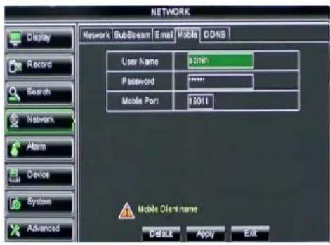
5.3.4.5 Mobile Set
The DVR is currently compatible with mobile phones running Andriod and Iphone on 3G networks.
text_image
NETWORK Display Record Search Network Alarm Device System Advanced Network SubStream Email Mobile DONS User Name 97min Password ****** Mobile Port 9011 Mobile Client name Default Apply ExitPicture 5-38
Click [Main menu→Network→Mobile] to enter into the [Mobile] interface shown as Picture 5-41.
User Name: indicate user name of DVR, and support numbers and characters and 1\~15 bits length
User password: indicate user password of DVR, and also support numbers and characters and 1\~15 bits length
Server port: Mobile monitoring port. Setting range is between 1024 and 65535.
Please note that the server port could not duplicate the port you have set to network set.
5.3.4.6 DDNS Set
DDNS (Dynamic DNS) is a service that register a domain name and the floating IP address with the DDNS server so that the domain name can be routed to the IP address even if the IP address is changed in a dynamic IP system.
User can visit a remote DVR by using DDNS on above three types (Static, DHCP and PPPoE)
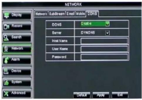
text_image
NETWORK Display Record Search Network Alarm Device System Advanced Network SubStream Email Mobile DDR5 Disable Server DYNONS Host Name: User Name: Password: Default Apply ExitPicture 5-39
You can apply for a DDNS account for free at the web www.3322.org or www.dyndns.org.
You can register on DVR2009.3322.org or dyndns.org website and get a domain name, user name, and password.
Server: select DDNS provider
Host name: input the host domain name you have registered at dynamic domain name system, such as: DVR2009.3322.org;
User Name: Input a user name registered before applying for a domain name;
Password: Input a password you set when registering a user name.
Click [Apply] button and restart the DVR; and then enter the domain name (such as: http://superdvr.3322.org:8080) to visit your remote DVR.
5.3.5 Alarm
5.3.5.1 Motion
Click [Main menu→Alarm→Motion] to enter into the interface shown as Picture 5-40
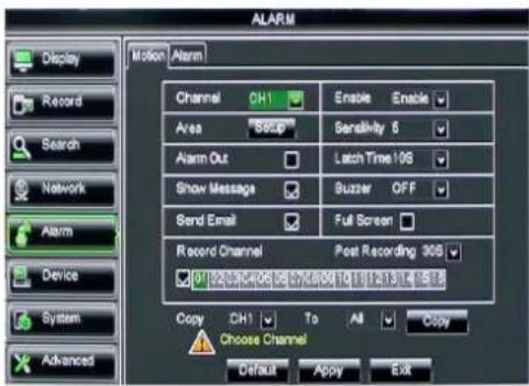
text_image
ALARM Display Record Search Network Alarm Device System Advanced Motion Alarm Channel CH1 Enable Enable Area SBCP Sensitivity 6 Alarm Out Latch Time 106 Show Message Buzzer OFF Send Email Full Screen Record Channel Post Recording 305 0 22/07/2008 0 27/05/2010 1 1 1 1 3 4 5 6 Copy CH1 To All Copy Choose Channel Default Apply ExitPicture 5-40
➢ Channel: allow you enable/disable the motion function for any channel.
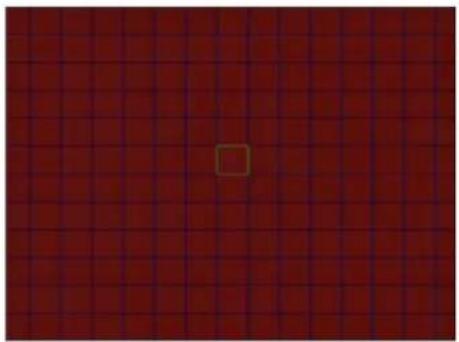
Area: Click the [Setup] button to enter into area setup interface shown as Picture 5-41.
Sensitivity: allow you to set sensitivity level of motion detection from higher to low with 8 being the most sensitive.
➢ Alarm out: allow you connect external alarm sensor.
Latch time: you can set how long the buzzer will sound when object move is detected (10s, 20, 40s, 60s);
Show Message: You can set show message on the screen when motion alarm is detected.
➢ Buzzer time: you can set how long the buzzer will sound when motion is detected (10s, 20, 40s, 60s);
➢ Send Email : Allows you set the alarm images is issued to a specified email.
Full screen Alarm: The function is defaulted to "On". When the motion is detected, the corresponding channel will be switched to the full screen mode.
Record Channel: the record channel will be activated when the object move is detected.
Post Recording: you can set how long alarm record will last when alarm ends (30s, 1minute, 2minute, 5minute).
➢ Copy: allow you copy current channel parameters to any other channel or all channels.
natural_image
Red grid background with a small square marker in the center (no text or symbols)Picture 5-41
The channel will be separated into a 15X12grids (PAL mode) or 15X10grids (NTSC mode). When any object moves into the motion detection area, and the area where the object is located is displayed in red and motion detection will be triggered. In the semi-transparent area the motion detection is not activated.
5.3.5.2 Alarm Set
Click [Main Menu→Alarm→Alarm] to enter into the below window shown as Picture 5-42. Now you can perform alarm set based on different status. Details please refer to List 5-1.
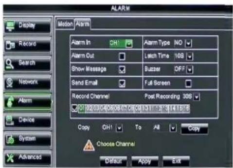
text_image
ALARM Motion Alarm Alarm In CHI Alarm Type INO Alarm Out Latch Time 109 Show Message Buzzer OFF Send Email Full Screen Record Channel Post Recording 308 Device 02.0/40.0/6.0/7.0/8.5/10.1/11.2/12.3/14.1/15 Copy OH1 To All Copy Choose Channel Default Apply ExitPicture 5-42
No: allow you select one desired channel I/O Status: allows you select the three options – NO (Normal Open), NC (Normal Close) and OFF. Set to “Normal Open”, I/O status Alarm will be activated while sensor is ON; set to “Normal Close”, I/O status alarm will be activated while sensor is OFF; set to “OFF”, I/O status alarm will not be triggered.
➢ Alarm out: allow you connect external alarm sensor.
➢ Latch time: you can set how long the buzzer will sound when external sensor alarm is detected (10s, 20, 40s, 60s);
Show Message: You can set show message on the screen when sensor alarm is detected.
➢ Buzzer time: you can set how long the buzzer will sound when sensor alarm is detected (Off, 10s, 20, 40s, 60s);
➢ Send Email : Allows you set the alarm images is issued to a specified email.
Full screen Alarm: The function is defaulted to "On". When the motion detection or
external alarm is triggered, the corresponding channel will be switched to the full screen mode.
Record Channel: allow you select channels you want to record.
Post Recording: you can set how long alarm record will last when alarm ends (30s, 1minute, 2minute, 5minute);
➢ Copy: allow you copy all the setting of one channel to other ones.
| Alarm Type Function | |
| Video Loss | Sends alarm when DVR can't receive video signal (such as camera damage, cable broken or damaged or power supply malfunction). |
| Motion Detection | When an object moves into motion detection area, alarm will be triggered. You can adjust sensitivity level to suit the needs of your actual application environment. |
| I/O Status | System can convert alarm signal triggered by external sensor into signal identified by system. |
| HDD loss | When Hard Drive is not detected (HDD damage, power supply malfunction), or HDD auto-overwrite is off, and free space is not enough, an alarm will be triggered. |
List 5-1
5.3.6 Device
5.3.6.1 HDD Set
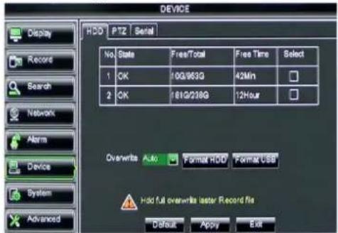
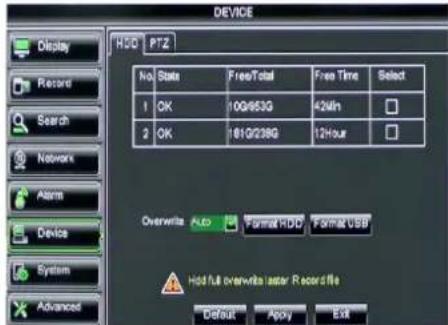
Click [Main menu→Device→HDD] to enter into the interface shown as Picture 5-43.
text_image
DEVICE HDD | PTZ | Serial No State FreeTotal Free Time Select 1 OK 10G/963G 42Min 2 OK 181G/228G 12Hour Overwrite Auto Format HDD Format USB Hold full overwrite later Record file Default Apply Exit Record Search Network Alarm Device System AdvancedPicture 5-43
text_image
DEVICE HDD PTZ No State FreeTotal Free Time Select 1 OK 10G/653G 42min 2 OK 181G/238G 12Hour Overwrite Auto Format HDD Format USB Hold full overwrite laser Record file Default Apply Exit Record Search Networks Alarm Device System AdvancedThis figure is only for D9016 / CIF model reference
When DVR is connected to a HDD, the system will automatically detect if HDD is normal or not;
If the cable connected to HDD is loosen or HDD is abnormal, HDD status will be shown as "No Disk", or, If HDD need to be formatted, status will be shown as "no format", otherwise, the HDD status will be shown as "Normal"
text_image
DEVICE FDD | PTZ | Serial No State Free/Total Free Time Select 1 OK 100%K3G 42Min Warning Format will remove all data from HDC OK CANCEL Default Apply ExitPicture 5-44
text_image
DEVICE HDD PTZ No State Free/Total Free Time Select A OK F00/R3G 40Min Warning Format will remove all data from HDD OK CANCEL Default Apply ExitThis figure is only for D9016 / CIF model reference
NO: indicate HDD no pre-seted by system.
➢ Status: : It will be available only when HDD have been formatted.
Total Space – Total size of the hard drive currently installed.
Free Space – Total amount of free space available on the hard drive currently installed.
Useable Rec. Time – Free space currently available in hours.
Auto-overwrite – When set to ENABLE the DVR will record over the oldest files on the hard drive. The DVR will always be able to record events as they happen, however, it does means that you'll need to get important events off the HDD before they're overwritten; and if overwrite is set to DISABLE the DVR will stop record once the DVR is full. Whilst you won't lose old footage, you run the risk of missing new events as they happen. Be sure you want to do this before selecting it.
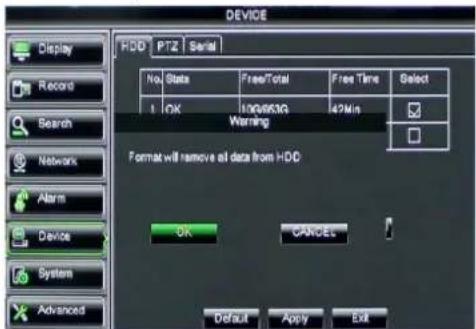
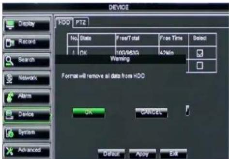
HDD Format – Formatting the HDD will erase all data (i.e. footage) which is stored on it, and re-create the FAT (file allocation table).
USB Format - If you have a USB flash drive connected to the DVR, you can format that, too. To do this, click the [USB Format] button and click [OK].
Note: It is an important first step when configuring your DVR to make sure that the hard drive (HDD) options are correctly set. So, strongly suggest that you do format the HDD before start the first record.
5.3.6.2 PTZ Set
Click [Main Menu→Device→PTZ] to enter into the below window shown as Picture 5-45
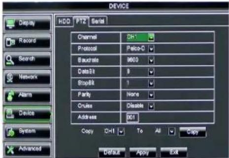
text_image
DEVICE Display HDD P12 Serial Record Search Network Alarm Device System Advanced Channel D+1 Protocol Palco-D Baustrate M600 DataBit 9 StopBit 1 Parity None Cruise Disable Address 001 Copy D+1 To All Copy Default Apply ExitPicture 5-45
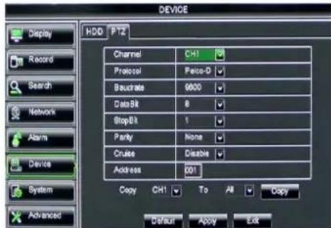
text_image
DEVICE HDD PTZ Channel CH1 Protocol Pace-D Bachrate 6000 Data Bit 8 Stop Bit 1 Parity None Cruise Disable Address 001 Copy CH1 To All Copy Default Apply ExitThis figure is only for D9016 / CIF model reference
You could select the channel you desire to control and set PTZ protocol (Pelco-D or Pelco-P), Baud Rate (1200, 2400, 4800, 9600), Data bit (8, 7, 6, 5), Stop bit (1, 2), Parity Check (None, Odd, Even, Mark, Space), Address Code and Cruise status respectively. Please note the PTZ device can be activated only when a channel in connection with the PTZ camera is selected.
5.3.6.3 Serial Set
Enter into the [Main menu→Device→Serial Set] interface shown as Picture 5-46
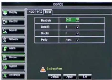
text_image
DEVICE Display HDD PTZ Serial Record Search Network Alarm Device System Advanced Baudrate 3400 DataBit 9 StepBit 1 Parity None Set BaudRate Default Apply ExitPicture 5-46
When operate DVR via keyboard, it is required to set communication protocol.
➢ Baud rate: set baud rate of serial communication.
Data bit: set data bit of serial communication.
➢ Stop bit: set stop bit.
Parity Check: set parity check to
5.3.7 System
5.3.7.1 General
Click [Main Menu→System→General] to enter into the interface shown as Picture 5-47
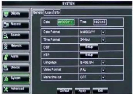
text_image
SYSTEM General Users Info Date 09/02/2011 Time 14:21:48 Data Format MWD/DYY Time Format 24-hour DST SET NTP SET Language ENGLISH Video Format PAL Menu time out OFF Default Apply Exit Record Search Network Alarm Device System AdvancedPicture 5-47
You will be allowed to modify system date, time, date/time format, language, video format and auto logout.
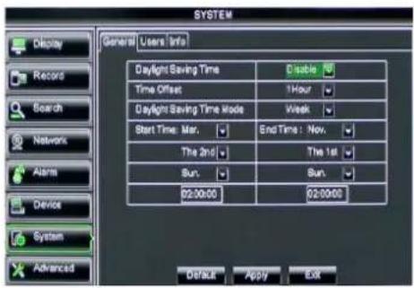
And click [DST Setup] button to enter into the below interface shown as Picture 5-48.
5.3.7.2 DST Set
text_image
SYSTEM Display Record Search Networks Alarm Device System Advanced General Users Info Daylight Saving Time Disable Time Offset 1Hour Daylight Saving Time Mode Week Start Time: Mar. End Time: Nov. The 2nd The 1st Sun. Sun. 02:00:00 02:00:00 Default Apply ExitPicture 5-48
Enter into the interface shown as Picture 5-48 and you are allowed to set DST status and mode.
5.3.7.3 Network Time Protocol (NTP) Service
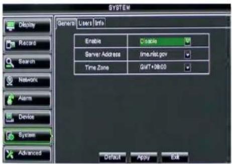
Click [Main menu→System→General→NTP] to enter into the interface shown as Picture 5-49
text_image
SYSTEM General Users Info Enable Disable Server Address time.nist.gov Time Zone GIT+08:00 Default Apply ExitPicture 5-50
NTP Service : Allow you enable/disable the NTP function.
Server Address: currently support three servers, including time.windows.com, time.nist.gov and pool.ntp.org.
Time Zone: System supports thirty Time Zones.
Update now: Click [Update Now] button to change the above NTP set.
Note: The above change will be available only when system connected to internet. And When NTP function is set to "Enable", system will calibrate the time at every 00:07:50 and every start-up.
5.3.7.4 Users
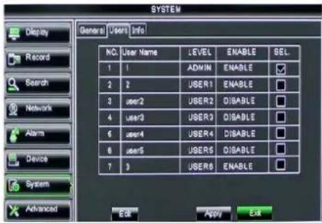
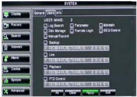
Click [Main Menu→System→users] option and then enter into the interface shown as Picture 5-51
text_image
SYSTEM General Users Info NO. User Name LEVEL ENABLE SEL 1 1 ADMIN ENABLE ✓ 2 2 USER1 ENABLE □ 3 user2 USER2 DISABLE □ 4 user3 USER3 DISABLE □ 6 user4 USER4 DISABLE □ 8 user5 USERS DISABLE □ 7 3 USERS ENABLE □ System Advanced Edit Apply ExitPicture 5-51
The model supports up to seven users with one Admin and seven users.
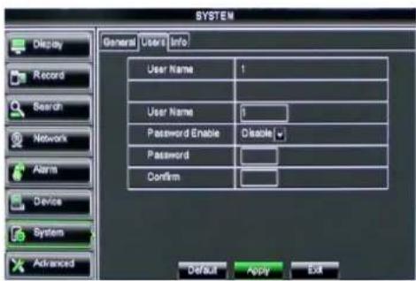
Click [Edit] button to enter into the [User Edit] interface shown as Picture 5-52
text_image
SYSTEM General Users Info User Name 1 User Name 1 Password Enable Disable Password Confirm Default Apply ExitPicture 5-52
User name consist of eight characters, password consist of 0\~9 and its fixed-length is 6 bit.
text_image
SYSTEM General Users Info USER, NAME: 2 Log Search Parameter Maintain Disk Manage Remote Login SEQ Control Manual Record Backup 01/02/2014 05:00 07:33:00 10:11 12:31:47 8:15 Live 01/02/2014 05:00 07:33:00 10:11 12:31:47 8:15 Playback 01/02/2014 05:00 07:33:00 10:11 12:31:47 8:15 PTZ Control 01/02/2014 05:00 07:33:00 10:11 12:31:47 8:15 AI Clear Apply Exit Record Search Network Alarm Device Systems AdvancedPicture 5-53
[Admin] is authorized to set common user's authority.
Log Search: allow you check the entire system log.
Parameter: allow you set all the parameters.
➢ Maintain: allow you update version, recover ex-factory value, device reboot and shut down.
Disk Manage: allow you manage and control the HDDs.
➢ Remote Login: allow you remote login DVR.
Rotate Control: allow you sequence live screens for all the channels.
➢ Manual record: allow you manually start/stop record.
Backup: Tick-select the option, the user is allowed to backup the record of all the channels.
Live: Tick-select the option and the user is allowed to view all the live images for all the channels.
➢ Playback: Tick-select the option and the user is allowed to playback the record you selected.
PTZ control: Tick-select the option and the user is allowed to perform the PTZ operation for the selected channel.
5.3.7.5 Information
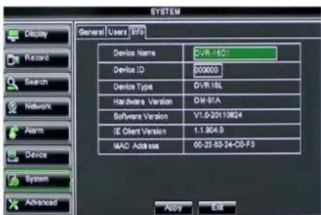
Click [Main Menu→System→Info] and then enter into the interface shown as Picture 5-54
text_image
SYSTEM General Users Info Device Name DVR-16C1 Device ID 000000 Device Type DVR 18L Hardware Version DM-91A Software Version V1.0-20110824 IE Client Version 1.1.004.0 MAO Address 05-22-83-24-CD-F0 Apply ExitPicture 5-54
Now user can check the current Device name, Device ID, Device type, Device S/N, MAC address, IE version, Software version, Panel version etc.
5.3.8 Advanced
5.3.8.1 Maintain
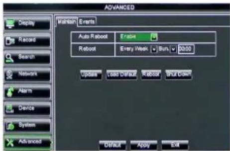
Click [Main menu→Advanced→Maintain] to enter into the maintain interface shown as Picture 5-55
text_image
ADVANCED Display Record Search Network Alarm Device System Advanced Maintain Events Auto Roboot Erabine Roboot Every Week Sun 00:00 Update Load Default Roboot Shut Order Default Apply ExitPicture 5-55
Auto Maintain: You can enable the auto maintain function regularly as per user's need.
Auto Reboot: you can also set system auto reboot regularly (daily/weekly/monthly) as per user's need.
Load Default: If [Load Default] is selected, you can initialize the system to the ex-factory default.
➢ Reboot: Click [Reboot] button to manually restart DVR system.
Shutdown: Click the [Shutdown] button to shutdown the device.
System Upgrade:
- You can insert a USB memory into USB port for updating;
- Do not take out the USB memory or break the power during the update.
- When the update is done, system will be automatically restarted.
- Please manually recovery ex-factory default after system rebooting.

dvrupgrade
Picture 5-56
5.3.8.2 Event
Click [Main menu→Advanced→Event] to enter into the
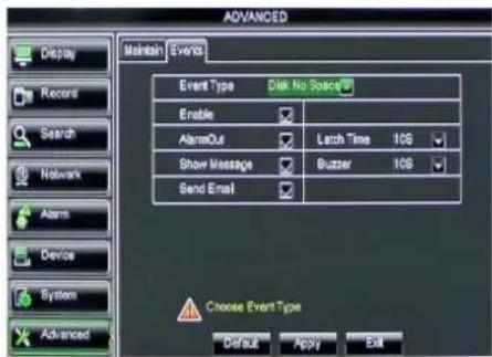
text_image
ADVANCED Display Record Search Network Alarm Device System Advanced Maintain Event Event Type Disk No Space Enable AlarmOut Larch Time 10S Show Message Buzzer 10S Send Email Choose Event Type Default Apply ExitPicture 5-57
Event Type: support the three abnormal types: Disk No Space, Disk Error and Video Loss.
➢ Enable: allow you activate abnormal alarm.
▶ Alarm out: select [Enable] or [Disable]
➢ Latch time: you can set how long the buzzer will sound when external sensor alarm is detected (10s, 20, 40s, 60s);
Show Message: You can set show message on the screen when sensor alarm is detected.
➢ Buzzer time: you can set how long the buzzer will sound when abnormal alarm is triggered (Off, 10s, 20, 40s, 60s);
Send Email : Allow you issue the alarm images to a specified email.
5.4 Menu Lock
Considering a system safety feature you can click [ ] on to lock system interface when leaving the DVR. If you want to login to the DVR again, you would input device code and password to unlock the interface shown as Picture 5-58
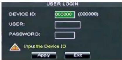
text_image
USER LOGIN DEVICE ID: 000000 (000000) USER: PASSWORD: Input the Device ID Apply ExitPicture 5-58
Friendly Reminder: Administrator has full authority over Main Menu operations and has an authority to limit common user's operation.
5.5 Split mode
The model displays 4/8 live images in the sequence of single, 4-split and 9-split modes. If you enter into 4-split mode, the live images will be displayed in turn CH1\~4, CH5\~8...and CH13\~16.
If you enter into 9-split mode, the live images will be displayed in turn CH1\~9→CH10\~16.
5.6 PTZ Control
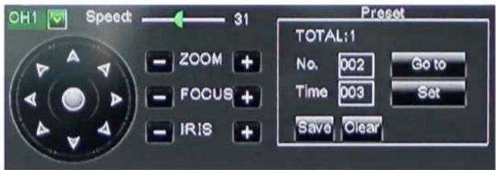
text_image
OH1 Speed: 31 ZOOM + FOCUS + IRIS + Preset TOTAL:1 No. 002 Go to Time 003 Set Save ClearPicture 5-59
We introduced setting PTZ parameters previously in section 5.3.6.2 – PTZ Set. Here we will discuss how to operate PTZ controls.

Click the [icon] icon to enter into [PTZ control] menu shown as Picture5-60. Now user can control the camera with Pan, Tilt and Zoom capabilities.
Click [Zoom-/+] button to zoom in / out the image; Click [Focus -/+] button to focus the image; Click [Iris -/+] button adjust iris to open or close.
Cruise Set
Open auto cruise function on PTZ setting menu if you want to setup cruise function (system default: off), and set up cruise channel, cur point and total quantity and stop time etc
How to set pre-set point
Total: set up pre-set point quantity
Cur Point: indicates starting point cruised. System default point is 01. The model support up to 255 pre-set points.
➢ Stop time: sets the stop time at each point
➢ GOTO: allow you go to a specific preset point.
Set: allow you set a set of specific preset points of a PTZ camera.
- Select a camera you desire to set a preset point;
- Adjust the camera in a desired direction;
- Click [Set] to set the point as preset point;
- Click [Save] to save the preset point;
- Follow the above step to add one more preset point.
Save: save all the preset points
Clean: allow you delete one selected preset point.
Note: Up to 254pre-sets per one camera can be stored. However, actual preset quantity differs depending on PTZ performance.
5.7 PIP Mode
You can display a Picture-in-Picture in live mode. PIP has two display modes, including 1X1 display mode and 1X2 display mode.
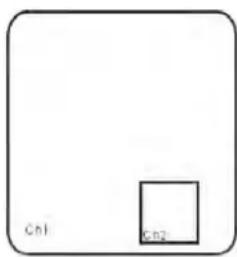
text_image
Cn1 Cn21x1 display mode
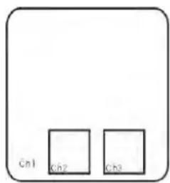
text_image
Cn1 Ch2 Ch31x2 display mode
5.8 Record search
You could enter into [Record Search] menu from Pop-up menu conveniently and quickly and search/playback the record histories. We introduced Record search details previously in Section 5.3.3.1.
5.9 Mute
Click the [icon, or press
5.10 Manual Record
You can start manual record function, or you also can click [ ] button on the Front panel or Remote controller to activate manual record. Please stop record manually once you activate manual record.
5.11 Stop record
To stop record quickly, please click the icon [ ] or [Stop] button on the front panel or remote controller.
5.12 Start Sequence
In the single mode, when entering into [Start sequence] menu, auto-sequence will be conducted at the set interval. Details please refer to section 5.3.1.2.
5.13 Start Cruise
If multiple presets are specified, the PTZ camera will automatically move to the entire preset one at a time whilst user activates [Start Cruise] options. If you want to stop cruise,
please click [] icon on the [Tool] column.
Chapter 6 Web Application Manager
6.1 Plug-in download and installation
Open your web browser and input the IP address and web port of DVR, such as: http://172.18.6.202:8080/. If your computer is connected to internet, it will download and install "ActiveX" Plug-in automatically. If your computer system is Vista, you may need to setup the user authority. Details please refer to the below picture: Start →setup→ control panel (Tick "√" use UAC to help protect your computer and confirm OK).
Vista system:

text_image
User Accounts > Turn User Account Control On or Off Search Turn on User Account Control (UAC) to make your computer more secure User Account Control (UAC) can help prevent unauthorized changes to your computer. We recommend that you leave UAC turned on to help protect your computer. Use User Account Control (UAC) to help protect your computer OK CancelVista
Win-7 system:
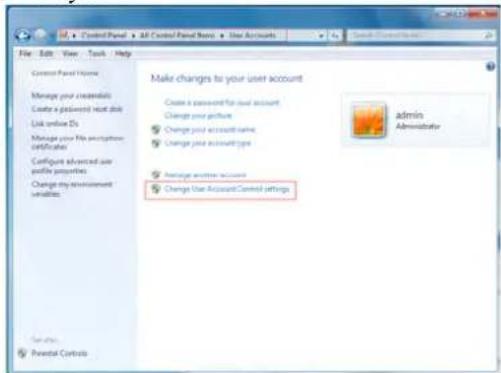
text_image
File Edit View Track Help Control Panel Home Manage your createnials Create a password next tile Link online IDs Manage your File certificate Configure advanced use write purposes Change my announcement variables. Make changes to your user account Create a password for dual account Change your picture Change your account name Change your account type Average user account Change Use Account Control settings admin Administrator Cancel... Potential ControlsWIN7-1
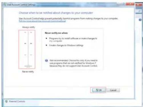
text_image
Choose when to be notified about changes to your computer Use Account Control? helps prevent potentially harmful programs from making changes to your computers. To ensure that the Account Control is checked. Always notify Never notify us when • Programs try to install software or make changes to my computer • Create changes to Windows settings ① Not recommended. Choose this only if you need to use programs that are not certified for Windows 2 because they do not support Use Account Control. Never notify. No OK Cancel Parental ControlsWIN7-2
Reminder: If the plug-in program is not downloaded successfully, please check if your browser's safety level or firewall setting is too advanced. Please run IE →Tools→Internet options→Internet Custom level→Enable the options (details please refer to the below Picture 6-2).
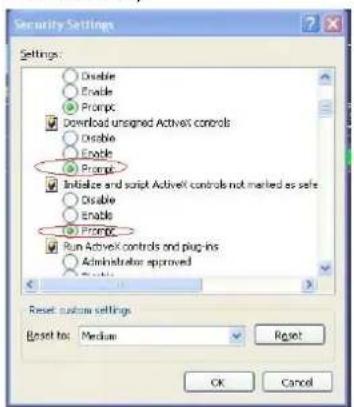
text_image
Security Settings Settings: Disable Enable Prompt Download unsigned ActiveX controls Disable Enable Prompt Initiative and script ActiveX controls not marked as safe Disable Enable Prompt Run ActiveX controls and plug-ins Administrator approved Reset: custom settings. Reset to: Medium Reset OK CancelPicture 6-1
If running the web application for the first time, you need about one minute to finish download and install plug-in, please wait patiently.
Note: If you want to use the undated webcam at one computer which you already login before, please delete the old IE webcam and click [Start→Run] to input the command characters: "regsvr32/u HiDvrOcx.ocx", then login again.
6.2 Web Application Manager Log-in
After plug-ins installation, please input user name, password and client port; and select
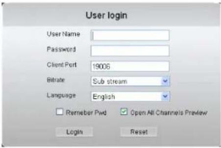
text_image
User login User Name Password Client Port 19006 Bitrate Sub stream Language English Remeber Pwd Open All Channels Preview Login ResetPicture 6-2
Now you click [Log-in] button, and then you are allowed to access a remote DVR and monitor live video images using Web browser anytime from virtually anywhere.
Noted that defaulted password is empty. System allows Administrator to set new password as per instructions in section 6.3.3 - [System set→User Configuration] menu.
6.3 Live interface
After successful logging-in web manager, you will enter into the Live interface shown as Picture 6-3
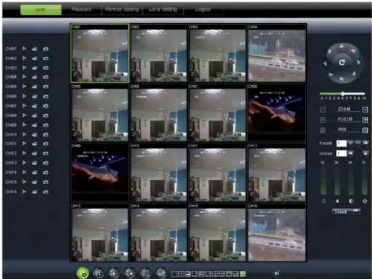
text_image
Live Playback Remote Setting Local Setting Login CHB1 CHB2 CHB3 CHB4 CHB5 CHB6 CHB7 CHB8 CHB9 CHB10 CHB11 CHB12 CHB13 CHB14 CHB15 CHB16 CHB17 CHB18 CHB19 CHB20 CHB21 CHB22 CHB23 CHB24 CHB25 CHB26 CHB27 CHB28 CHB29 CHB30 CHB31 CHB32 CHB33 CHB34 CHB35 CHB36 CHB37 CHB38 CHB39 CHB40 CHB41 CHB42 CHB43 CHB44 CHB45 CHB46 CHB47 CHB48 CHB49 CHB50 CHB51 CHB52 CHB53 CHB54 CHB55 CHB56 CHB57 CHB58 CHB59 CHB60 CHB61 CHB62 CHB63 CHB64 CHB65 CHB66 CHB67 CHB68 CHB69 CHB70 CHB71 CHB72 CHB73 CHB74 CHB75 CHB76 CHB77 CHB78 CHB79 CHB80 CHB81 CHB82 CHB83 CHB84 CHB85 CHB86 CHB87 CHB88 CHB89 CHB90 CHB91 CHB92 CHB93 CHB94 CHB95 CHB96 CHB97 CHB98 CHB99 Chb 100Picture 6-3
6.3.1 Menu Bar
Menu bar include [Live], [Replay], [Configuration], [Path Configuration] and [Logout] options
After running the Web Application Manager on your local PC, system will be defaulted to enter into

: Volume switch

: Record icon: record will be saved to a specified position after starting record.

:Snapshot function: allow you capture the live images and save it to a specified position. The imag should be saved as *.bmp format.

clicking the icon will close/open the current channel's live mode
Or click the right key of mouse on each
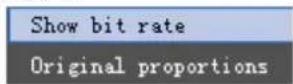
Show bit rate: show current bit rate;
Original Proportions: show original proportions.
Picture 6-4


: CH Display mode

: Allow you open all the

: Allow you close all the

: Display previous channels

: Display next channels

: Click the icon to enlarge current window to full screen; right-click to pop-up menu how allow you select
6.3.1.2 PTZ Control
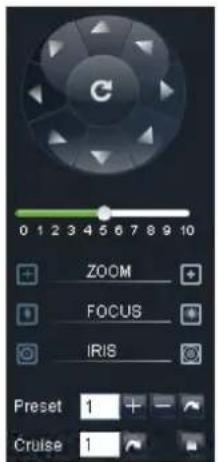
text_image
0 1 2 3 4 5 6 7 8 9 10 + ZOOM + ↓ FOCUS + ○ IRIS Preset 1 + - Cruise 1Picture 6-5
① PTZ moving Direction control: allow you control PTZ camera's direction. And the middle button is called [Auto-cruise] button.

PTZ speed control bar
Iris, Focus and Zoom control
: Preset setting/clear; Start cruise /stop cruise
6.3.1.3 Video control
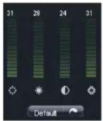
text_image
31 28 24 31 DefaultPicture 6-6
: Adjust video Hue;
■ : Adjust video brightness;
: Adjust video Contrast;
: Adjust video saturation;
: Recover ex-factory default value.
6.3.2 Playback
Click [] icon to enter into < playback> interface shown Picture 6-7.
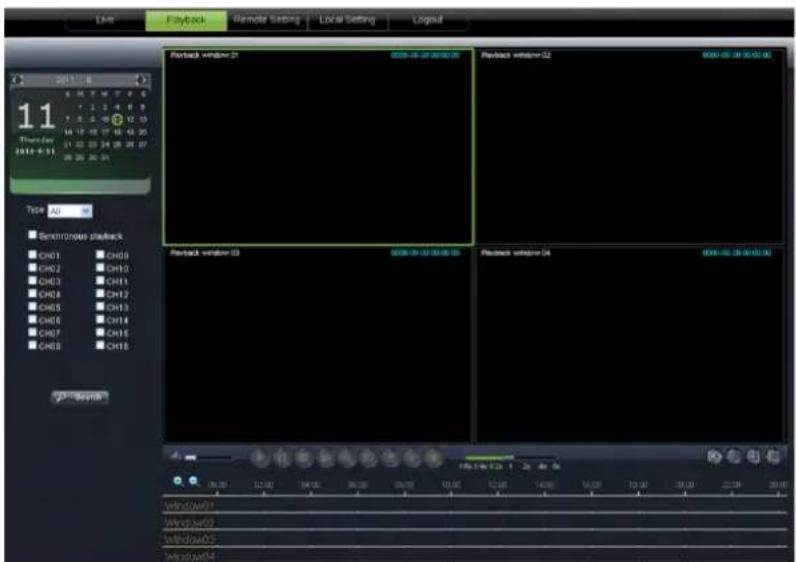
text_image
Live Playback Remote Setting Local Setting Logout 2011-06 11 Thunder 2011-06-03 Type: All ■ Semiprobus playback C#01 C#02 C#03 C#04 C#05 C#06 C#07 C#08 Playback window 21 C#08-05-03 20:00:00 Playback window 22 C#08-05-03 20:00:00 Playback window 23 C#08-05-03 20:00:00 Playback window 24 C#08-05-03 20:00:00 wind/w01 Window/w02 Window/w03 Windows/w04Picture 6-7
The Web Application Manager supports up to 4 channels playback simultaneously.
6.3.2.1 Record search
Firstly, select one day you want to check and tick-select
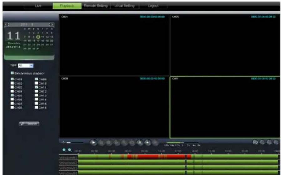
text_image
Live Playback Remote Setting Local Setting Logout 2015 11 Thursday 2013-8-23 Type: A0 Synchronous playback CH01 CH02 CH03 CH04 CH05 CH06 CH07 CH08 CH09 CH10 CH11 CH12 CH13 CH14 CH15 CH16 Ch01 00:00:00:00:00 CH01 00:00:00:00:00 CH02 00:00:00:00:00 CH03 00:00:00:00:00 CH04 00:00:00:00:00 CH05 00:00:00:00:00 CH06 00:00:00:00:00 CH07 00:00:00:00:00 CH08 00:00:00:00:00 CH1 00:00:00:00:00 Windows'Q1 Windows'Q2 Windows'Q3 Windows'Q4Picture 6-8
Secondly, select record type (Normal record, Alarm record and All) and then click < > Branch button shown as Picture 6-9. On the time axis, red part stand for alarm record, yellow stand for normal record and original part stand for no record during this period.
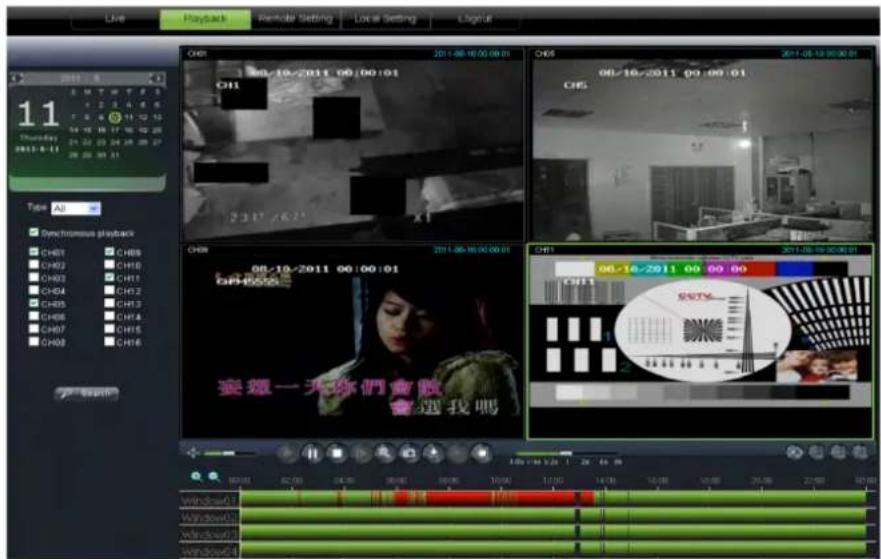
text_image
Live Playback Remote Setting Local Setting Layout 11 Thursday 2013-8-11 Type: All Synchronous playtrack CH01 CH02 CH03 CH04 CH05 CH06 CH07 CH08 CH09 CH10 CH11 CH12 CH13 CH14 CH15 CH16 2011-08-10 00:00:01 2011-08-10 00:00:01 2011-08-10 00:00:01 2011-08-10 00:00:01 2011-08-10 00:00:01 2011-08-10 00:00:02 2011-08-10 00:00:02 2011-08-10 00:00:02 2011-08-10 00:00:02 2011-08-10 00:00:02 2011-08-10 00:00:03 2011-08-10 00:00:03 2011-08-10 00:00:03 2011-08-10 00:00:03 2011-08-10 00:00:03 2011-08-10 00:00:04 2011-08-10 00:00:04 2011-08-10 00:00:04 2011-08-10 00:00:04 2011-08-10 00:00:04 2011-08-10 00:00:05 2011-08-10 00:00:05 2011-08-10 00:00:05 2011-08-10 00:00:06 2011-08-10 00:00:06 2011-08-10 00:00:06 2011-08-15 2.3.27 / 6.7. 2.3.27 / 6.7. 2.3.27 / 6.7. 2.3.27 / 6.7. 2.3.27 / 6.7. 2.3.27 / 6.7. 2.3.27 / 6.7. 2.3.27 / 6.7. 2.3.27 / 6.7. 2.3,4. 2.3,4. 2.3,4. 2.3,4. 2.3,4. 2.3,4. 2.3,4. 2.3,4. 2.3,4. 2.3,4. 2.3,4. 2.3,4. 2.3,4. 2.3,4. 2.3,4. 2.3,4. 2.3,4. 2.4,4. 2.4,4. 2.4,4. 2.4,4. 2.4,4. 2.4,4. 2.4,4. 2.4,4. 2.4,4. 2.4,4. 2.4,4. 2.4,4. 2.4,4. 2.4,4. 2.4,4. 2.4,4. 2.5,4. 2.5,4. 2.5,4. 2.5,4. 2.5,4. 2.5,4. 2.5,4. 2.5,4. 2.5,4. 2.5,4. 2.5,4. 2.5,4. 2.5,4. 2.5,4. 2.5,4. 2.5,4. 2.5,4. 3.3,4. 3.3,4. 3.3,4. 3.3,4. 3.3,4. 3.3,4. 3.3,4. 3.3,4. 3.3,4. 3.3,4. 3.3,4. 3.3,4. 3.3,4. 3.3,4. 3.3,4. 3.3,4. 3.3,4. TOMO! Windows/7: Windows/7: Windows/7: Windows/7: Windows/7: Windows/7: Windows/7: Windows/7: Windows/7: Windows/7: Windows/7: Windows/7: Windows/7: Windows/7: Windows/7: Windows/7: Windows/7: Windows/7: Windows/7: Windows/7: Windows/7: Windows/7: Windows/7: Windows/7: Windows/7: Windows/7:Picture 6-9
If you tick-select < 80% that means the selected channel will playback synchronously; otherwise, you could separately control the channels playback.
Thirdly, Click [☐] icon to start record playback. When mouse curse is moving on the time axis, the current time will appear in the screen.
Click [ ] to zoom in/out the time bar display ratio shown as Picture 6-12.
6.3.2.2 Playback control
Below Picture 6-13 is playback control bar

text_image
1.8x 1/4x 1/2x 1 2x 4x 8xPicture 6-10
Detail brief description is shown as below list
| Key | Description | Key | Description |
 | Play |  | Open/close audio |
 | Pause |  | Volume adjust |
 | Stop | 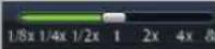 | Playback control bar (x1/2,1/4,1/8, normal, x2, x4, x8) |
 | By frame |  | Stop all the play |
 | Clip |  | Single channel mode |
 | Capture Quad mode |  | |
 | Download |  | Full screen |
 | Open all the channels | ||
 | Stop all the channels |
Record file clip
After opening playback, click [icon to clip the selected file; and click again to stop the clip function. Record clip file will be saved as *.264 format.
Snapshot function
Move the mouse curse to the channel you want to capture, and click [] don to capture the live images remotely. After capturing the images successfully, you are allowed to save it to a specified path shown as Picture 6-11. The captured file will be saved as *.bmp format
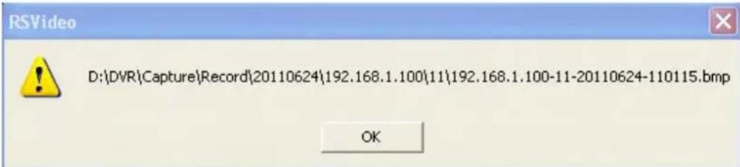
text_image
D:\{DVR\Capture\Record\20110624\192.168.1.100\11\192.168.1.100-11-20110624-110115.bmp OKPicture 6-11
Record file download
Click [icon to enter into the below interface shown as Picture 6-12.
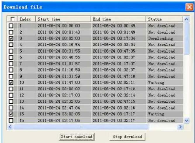
text_image
Download file Index Start time End time Statue 1 2011-06-24 00:00:00 2011-06-24 00:00:49 Not download 2 2011-06-24 00:01:48 2011-06-24 00:01:49 Not download 3 2011-06-24 00:02:00 2011-06-24 00:17:04 Downloading 4 2011-06-24 00:16:54 2011-06-24 00:32:04 Not download 5 2011-06-24 00:31:55 2011-06-24 00:47:05 Not download 6 2011-06-24 00:46:56 2011-06-24 01:02:07 Not download 7 2011-06-24 01:01:57 2011-06-24 01:17:07 Not download 8 2011-06-24 01:16:59 2011-06-24 01:32:07 Not download 9 2011-06-24 01:31:59 2011-06-24 01:47:10 Not download 10 2011-06-24 01:47:00 2011-06-24 02:02:11 Waiting 11 2011-06-24 02:02:02 2011-06-24 02:17:12 Not download 12 2011-06-24 02:17:03 2011-06-24 02:32:14 Not download 13 2011-06-24 02:32:05 2011-06-24 02:47:15 Not download 14 2011-06-24 02:47:04 2011-06-24 03:02:16 Not download 15 2011-06-24 03:02:05 2011-06-24 03:17:17 Waiting 16 2011-06-24 03:17:06 2011-06-24 03:32:17 Not download Start download Stop downloadPicture 6-12
Tick-select the record file you want to download and click [Start download] System will download the record file in turn and save to local PC.
6.3.3 Configuration
Click [Configuration] option to enter into the [Config] interface shown as Picture 6-13 and allow you set Display configuration, Record, Network, Alarm, Device, System parameters and Advance according to your actual request.
6.3.3.1 Display Configuration
Unfold [Display] option to find its sub-options: Live and Privacy zone
1、Live: Allow you modify channel name, Position, Show time and Record time. If show time is set to
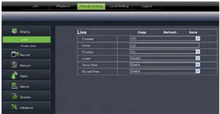
text_image
Live Playback Remote Setting Local Setting Logout Display Live Privacy Zone Record Network Alarm Device System Advanced Live Copy Refresh Save Channel CHI Name CHI Position UAL Current Disable Show Time Enable Record Time EnablePicture 6-13
2、Privacy zone: Each channel could set up to four privacy zones shown as Picture 6-14. Details parameters please refer to section 5.3.1.3. If you want to delete one privacy zone, please firstly select one zone, and then click
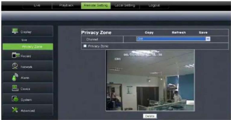
text_image
Live Playback Remote Setting Local Setting Logout Display Live Privacy Zone Record Network Alarm Device System Advanced Privacy Zone Copy Refresh Save Channel CH1 Privacy Zone 08/11-2013 12:16:38 CH1 DeletePicture 6-14
6.3.3.2 Record
Click
1、Record Parameters: Under [Record parameters] option, allow you set channel, record enable, pack time and Pre-record status shown as Picture 6-1
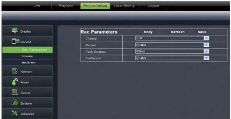
text_image
Live Playback Remote Setting Local Setting Layout Display Record Rec Parameters Schedule MacScreen Network Alarm Device System Advanced Rec Parameters Copy Refresh Save Channel CH1 Record Enable Pack Duration 90Min PreRecord EnablePicture 6-15
2、Schedule: Detailed parameters please refer to DVR local setting.
Green stand for Normal record; Yellow stands for Motion detection; Red stands for I/O triggered record.
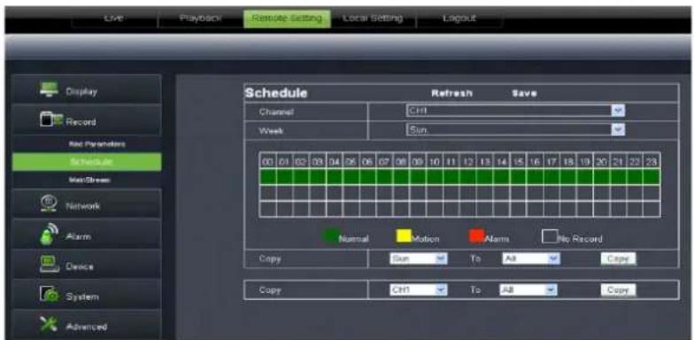
text_image
Live Playback Remote Setting Local Setting Layout Display Record Red Parameters Schedule Main Stream Network Alarm Device System Advanced Schedule Refresh Save Channel CHT Week Sun 00 01 02 03 04 05 06 07 08 09 10 11 12 13 14 15 16 17 18 19 20 21 22 23 Normal Motion Alarms No Record Copy Sun To All Copy Copy CHT To All CopyPicture 6-16
3、Main Stream: detailed settings please refer to DVR local setting. Herein allow user modifies the resolution, frame rate, Bit rate and audio of the record channel.
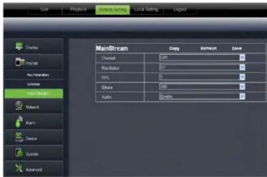
text_image
User Playbox Source Setting Local Setting Layout Display Proposed Non-Parameters Sequence MainStream Networks Actions Device Systems Advanced MainStream Copy Refresh Save Channel 341 Resolution 600 FILE 1 Balance 188 Audio EnablePicture 6-17
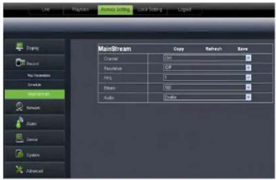
text_image
Live Playback Remote Setting Local Setting Logout Display Record Auto Parameters Schedule MainStream Channel Ctrl Resolution GIF FPS 5 Stream 100 Audio Enable Save Alum Device System AdvancedThis figure is only for D9016 / CIF model reference
6.3.3.3 Network Parameters
Unfold
1、The model support three network type, including Static, DHCP and PPPoE
Static: System default
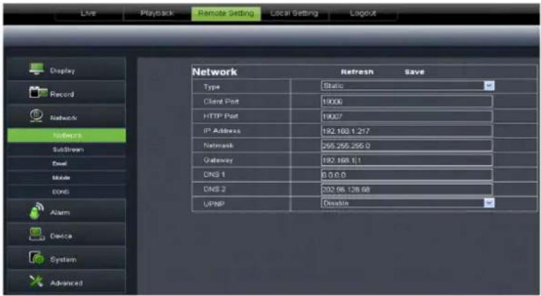
text_image
Live Playback Remote Setting Local Setting Logout Display Record Network Networks Substream Email Mobile Core Alarm Device System Advanced Network Refresh Save Type Static Client Port 19006 HTTP Port 19007 IP Address 192.183.1.217 Network 255.255.255.0 Gateway 192.183.1.1 DNS 1 0.0.0.0 DNS 2 202.96.126.68 UPNP DisablePicture 6-18
DHCP: Set network type to "DHCP" shown as Picture 6-19. Relative parameters should be consistent with DVR local setting.
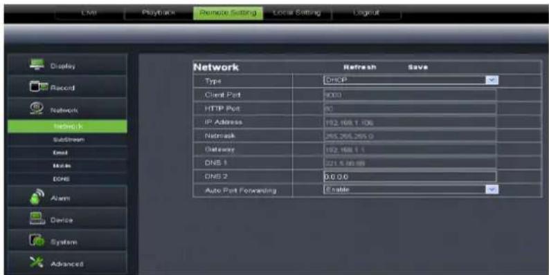
text_image
Display Record Network Network Substream End Mode DNS Alarm Device System Advanced Network Refresh Save Type DHCP Client Port 9000 HTTP Port 80 IP Address 192.168.1.106 Netmask 295.206.295.0 Dataway 192.168.1.1 DNS 1 221.4.08.88 DNS 2 0.0.0.0 Auto Port Forwarding EnablePicture 6-19
Set network type to "PPPoE" shown as Picture 6-20. Its user name and password should be consistent with DVR local setting.
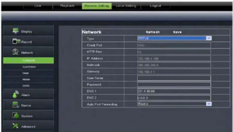
text_image
Live Playback Remote Setting Local Setting Logout Display Record Network network Switch Email Mode Odds Alarm Device System Advanced Network Refresh Save Type PPRGE Client Port 1000 HTTP Port 100 IP Address 192.168.1.106 Netmask 255.255.255.0 Gateway 192.168.1.1 User Name Password DNS 1 231.6.88.88 DNS 2 0.0.0.0 Auto Port Forwarding EnablePicture 6-20
2、Sub stream (shown as Picture 6-21): Relative parameters should be consistent with DVR local setting.
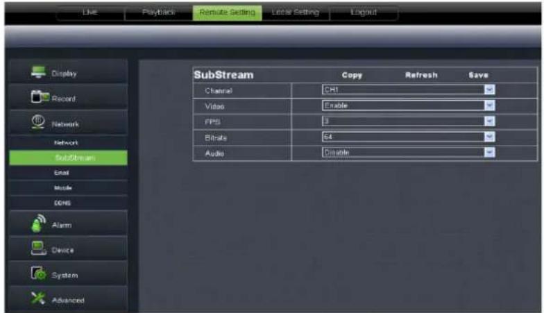
text_image
Live Playback Remote Setting Local Setting Logout Display Record Network SubStream Email Mode COMS Alarm Device System Advanced SubStream Copy Refresh Save Channel CH1 Video Enable FPS 3 Bitrate 64 Audio DisablePicture 6-21
3、Email setting: Click [Email setting] option to allow you set alarm email configuration parameters shown as Picture 6-22. Detailed parameters should be consistent with DVR local setting.
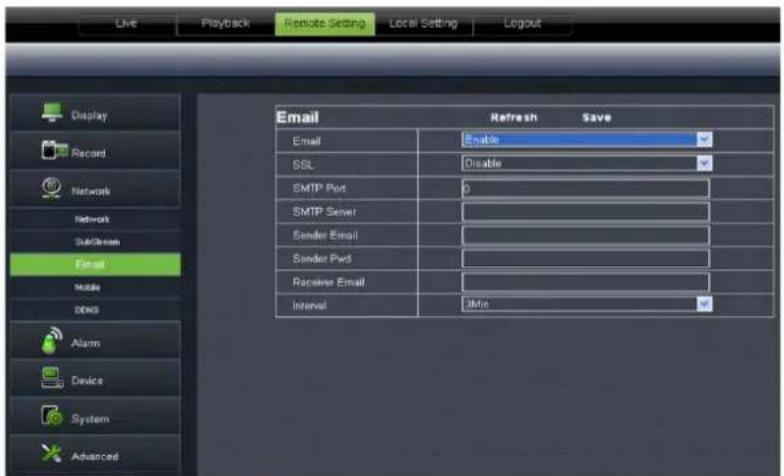
text_image
Live Playback Remote Setting Local Setting Logout Display Record Network Network SubStream Email Mobile DOS Alarm Device System Advanced Email Refresh Save Email Enable SSL Disable SMTP Port 0 SMTP Server Sender Email Sender Pvd Receiver Email Interval 0MinPicture 6-22
4、Mobile: Its user name, password and port No should be consistent with DVR local setting shown as Picture 5-23.
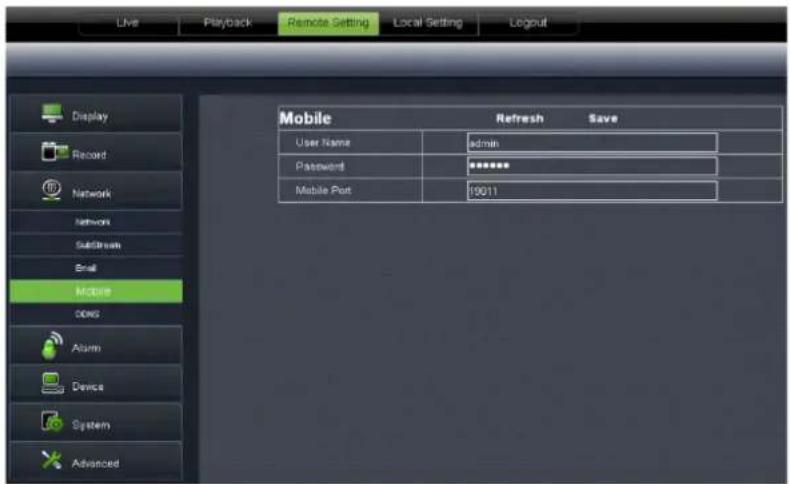
text_image
Live Playback Remote Setting Local Setting Logout Display Record Network Networks Subdriem Email Mobile DNS Alum Device System Advanced Mobile Refresh Save User Name admin Password ****** Mobile Port 19011Picture 6-23
5、DDNS Setting: After user applies for DDNS service shown as Picture 6-24, you could enable
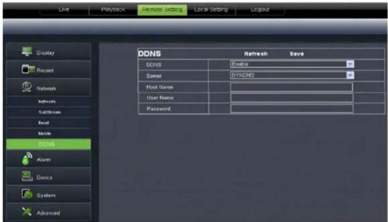
text_image
Live Playback Remote Setting Local Setting Logout Display Record Network Network Back Mode DDNS Alarm Device System Advanced DDNS Refresh Save DDNS Enable Server DYNDNS Host Name User Name PasswordPicture 6-24
6.3.3.4 Alarm Set
Click
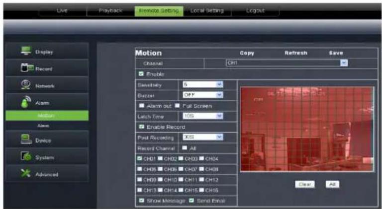
text_image
Live Playback Remote Setting Local Setting Logout Display Record Network Alarm Motion Alarm Device System Advanced Motion Copy Refresh Save Channel CH1 Enable Electricity S Buzzer OFF Alarm out Full Screen Latch Time IOS Enable Record Post Recording IOS Record Channel All CH01 CH02 CH03 CH04 CH05 CH06 CH07 CH08 CH09 CH10 CH11 CH12 CH13 CH14 CH15 CH16 Show Message Send Email Clear A2Picture 6-25
1、Motion Detection: allow you configure its
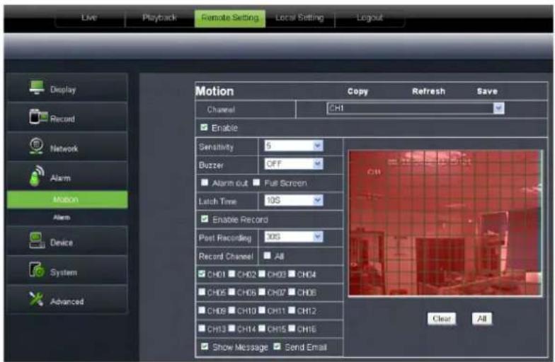
text_image
Live Playback Remote Setting Local Setting Logout Display Record Network Alarm Motion Alarm Device System Advanced Motion Copy Refresh Save Channel CH1 Enable Sensitivity 5 Duzzer OFF Alarm out ▪ Full Screen Latch Time 10S Enable Record Peel Recording 10S Record Channel ▪ All CH01 ▪ CH02 ▪ CH03 ▪ CH04 CH05 ▪ CH06 ▪ CH07 ▪ CH08 CH09 ▪ CH10 ▪ CH11 ▪ CH12 CH13 ▪ CH14 ▪ CH15 ▪ CH16 Show Message ▪ Send Email Clear AllPicture 6-26
2、I/O Alarm: allow you configure ,
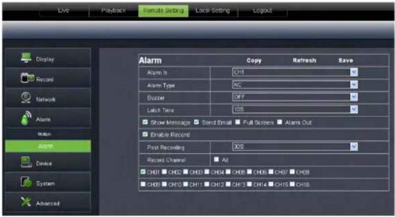
text_image
Live Playback Remote Setting Local Setting Logout Display Record Network Alarm Note Alarm Device System Advanced Alarm Copy Refresh Save Alarm In CH1 Alarm Type NC Buzzer OFF Latch Time 10S Show Message ▼ Send Email ▼ Full Screen ▼ Alarm Out Enable Record Past Recording 30S Record Channel □ All CH01 □ CH02 □ CH03 □ CH04 □ CH05 □ CH06 □ CH07 □ CH08 CH09 □ CH10 □ CH11 □ CH12 □ CH13 □ CH14 □ CH15 □ CH16Picture 6-27
6.3.3. 5 Device
Click
1、HDD: allow you check out HDD status and overwritten time shown as Picture 6-28. Detail setting should be consistent with DVR local setting.
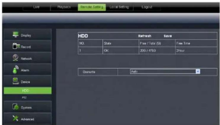
text_image
Live Playback Remote Setting Local Setting Logout Display Record Network Alarm Device HDD PTZ System Advanced HDD Refresh Save NO. State Free / Total (9) Free Time 1 OK 20G / 476G 2Hour Overwrite AutoPicture 6-28
2、PTZ Configuration (shown as Picture 6-29): details setting should be consistent with DVR local setting.
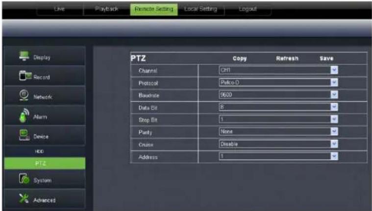
text_image
Live Playback Remote Setting Local Setting Logout Display Record Network Alarm Device HCG PTZ System Advanced PTZ Copy Refresh Save Channel CH1 Protocol Pelco-D Baudate 3600 Data Bit 8 Stop Bit 1 Parity None Crude Disable Address 1Picture 6-29
6.3.3. 6 System
Click
1、General: User could check DVR's language and video system, and also set system time, date format, DST and NTP shown as Picture 6-30. Details setting should be consistent with DVR local setting.
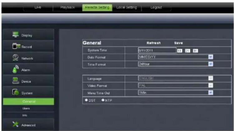
text_image
Live Playback Remote Setting Local Setting Logout Display Record Network Alarm Device System General Users Into Advanced General Refresh Save System Time 9/11/2011 17 21 31 Data Format 4M/CD/VY Time Format 24Hour Language 5M/CL/H Video Format PAL Menu Time Out 1Min ● DST ● NTPPicture 6-30
2、Users: Allow you configure user name and password shown as Picture 6-31. Details setting should be consistent with DVR local setting.
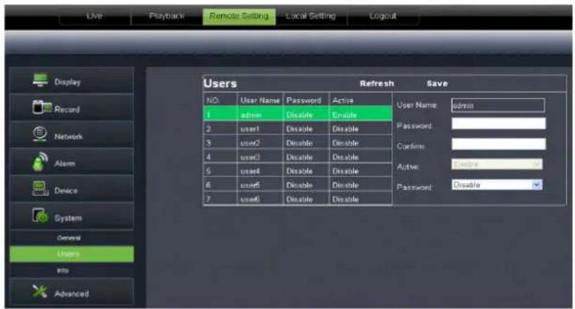
text_image
Live Playback Remote Setting Local Setting Logout Display Record Network Alarm Device System General Users Info Advanced Users Refresh Save NO. User Name Password Active User Name: admin 1 admin Disable Enable Password: 2 user1 Disable Disable 3 user2 Disable Disable Confirm: 4 user3 Disable Disable Active: 5 user4 Disable Disable Password: 6 user5 Disable Disable Password: 7 user6 Disable DisablePicture 6-31
3、Information: Allow you check out device name, number, type, MAC address, software version, IE version and hardware version shown as Picture 6-32.
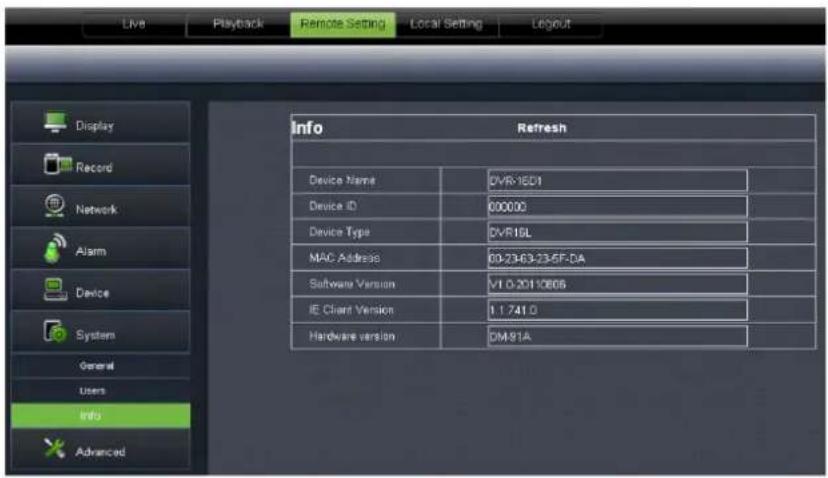
text_image
Live Playback Remote Setting Local Setting Layout Display Record Network Alarm Device Systems General Users Info Advanced Info Refresh Device Name 0VR-1ED1 Device ID 000000 Device Type 0VR16L MAC Address 00-2343-23-5F-DA Software Version V1.0.2010806 IE Client Version 11.741.0 Hardware version DM91APicture 6-32
6.3.3.7 Advanced
Click
1、System update: allow you upgrade DVR system remotely shown as Picture 6-33.
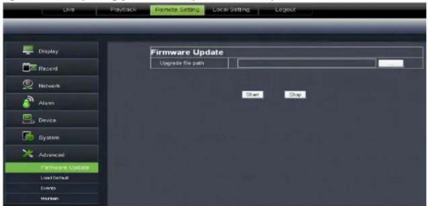
text_image
Live Playtrack Remote Setting Local Setting Logout Display Record Network Alarm Device System Advanced Firmware Update Load Default Events Maintain Firmware Update Upgrade file path Start StopPicture 6-33
Please follow below steps to upgrade the system:
a. Select the upgrade file's path shown as Picture 6-34. Please note that the format of upgrade file is *.sw.
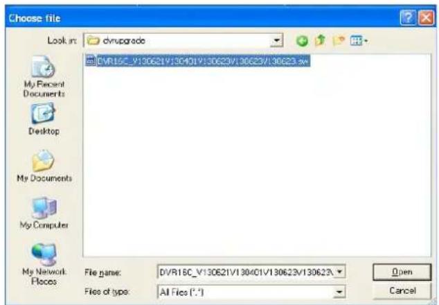
text_image
Choose file Look in: dvuprgrade My Recent Documents Desktop My Documents My Computer My Network Places DVR15C_V130621V130401V130623V130623.xv File name: DVR15C_V130621V130401V130623V130623 Files of type: All Files (*.*)Picture 6-34
b. Click
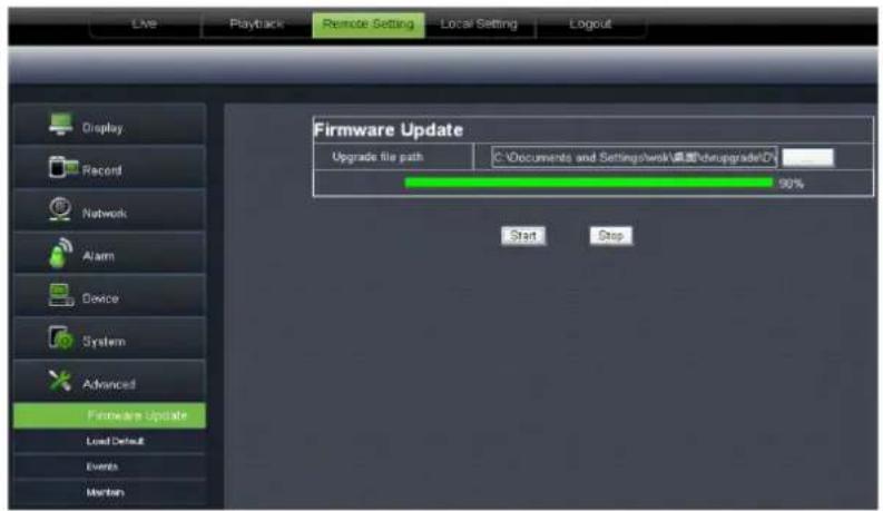
text_image
Live Playback Remote Setting Local Setting Logout Display Record Network Alarm Device System Advanced Firmware Update Load Default Events Maintenance Firmware Update Upgrade file path C:\Documents and Settings\work\桌面\dnupgrade(D) 90% Start StopPicture 6-35
2、Load Default: allow you recover defaulted parameters of DVR remotely shown as Picture 6-36. Details setting should be consistent with DVR local setting.
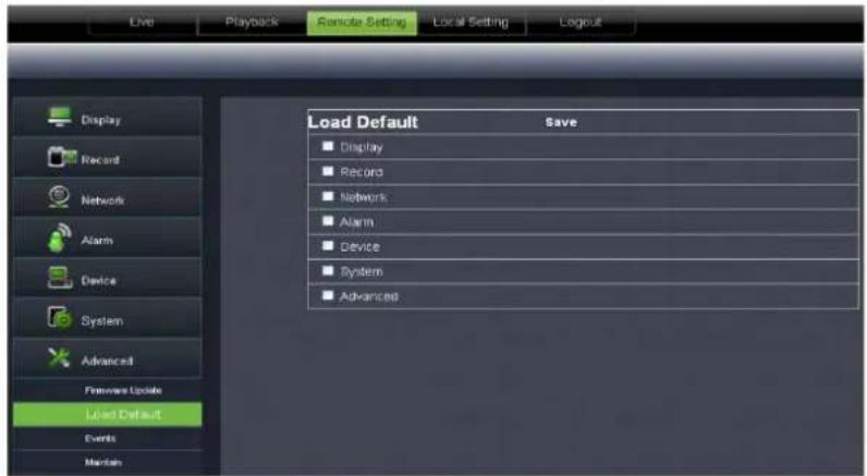
text_image
Live Playback Remote Setting Local Setting Logout Display Record Network Alarm Device System Advanced Firewalls Update Load Default Events Maintain Load Default Save ■ Display ■ Record ■ Network ■ Alarm ■ Device ■ System ■ AdvancedPicture 6-36
3、Events: allow you configure abnormal type, buzzer output time, and alarm email and show message shown as Picture 6-37. Details setting should be consistent with DVR local setting.
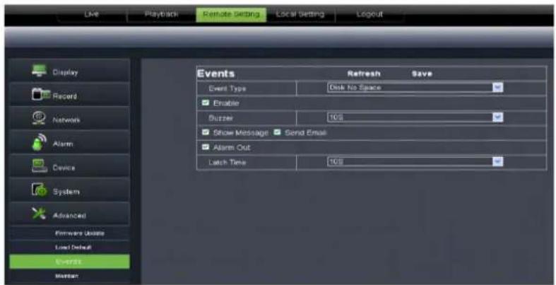
text_image
Live Playback Remote Setting Local Setting Logout Display Record Networks Alarm Device System Advanced Firmware Usites Load Default Overpass Mission Events Refresh Save Event Type Disk No Space Enable Suzzer 10% Show Message Send Email Alarm Out Latch Time 10%Picture 6-37
4、Maintain: allow you set auto system maintain for DVR remotely shown as Picture 6-38. Detail setting should be consistent with DVR local setting.
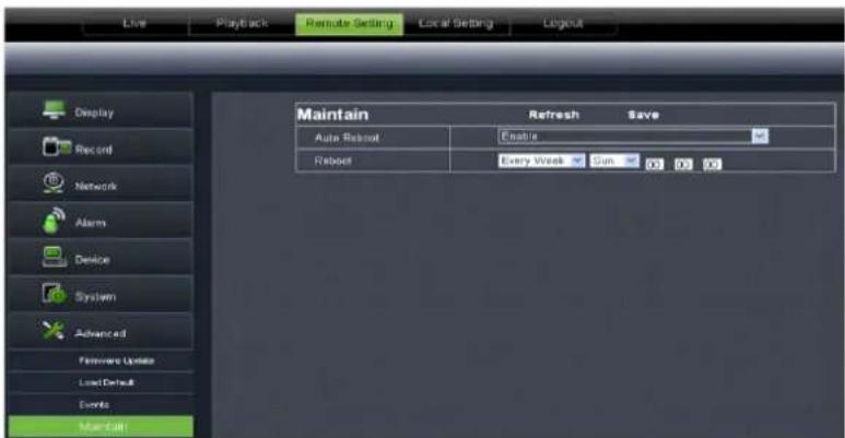
text_image
Live Playback Remote Setting Local Setting Logout Display Record Network Alarms Device System Advanced Fireworks Update Load Default Events Main Start Maintain Refresh Save Auto Retout Enable Reboot Every Week Sim 00 00 00Picture 6-38
6.3.4 Local setting
Under
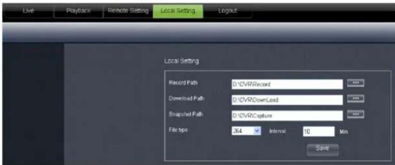
text_image
Live Playback Remote Setting Local Setting Logout Local Setting Record Path D:\DVR\Record Download Path D:\DVR\Download Snapshot Path D:\DVR\Capture File type 264 Interval 10 Min SavePicture 6-39
6.3.5 Logout
Click the [] icon to return back the log-in interface.
Chapter 7: Appendix
7.1 Operation Function Table
| Type Title Description Page | |||
| Basic setting | Time setting | Set system date/time, display format and day-light saving time | 26 |
| Language select | Set system language | 27 | |
| Channel setting | Set CH title and position; adjust image color parameter value; set CH display to ON / Off and time display/recording time overlaying to On/Off. | 9 | |
| Record setting | Set image quality, resolution, volume, record mode an pack time | 10 | |
| Record search | Time based search, channel based search and rec. mode based search. | 12 | |
| Record Playback | Specified time playback, scheduled playback, file list playback | 12 | |
| Playback mode | Play, play frame by frame, multi-speed forward and multi-speed rewind | 13 | |
| File backup | U flash disk and removable HDD backup, DVD recorder backup and network download | 13 | |
| HDD Manage Check HDD status, usage space, setting HDD auto-overwrite | 15 | ||
| VID/AUD Setting | Adjust VGA resolution, select system and volume control, set interval and channel display | 26 | |
| Advanced Setting | User password Set or modify user password 26 | ||
| Alarm setting | Set HDD loss, HDD space, video loss, I/O status, alarm management and Email alarm | 15 | |
| Motion detection | Set on/off status of MD; select sensitivity and set motion detection area. | 25 | |
| PTZ setting | Select CH and set PTZ protocol, baud rate and PTZ address for the CH | 19 | |
| Mobile surveillance Set user name, password and server port. | 19 | ||
| System maintenance | Set system auto maintenance, maintenance time regularly, system upgrade, ex-factory default value recovery and manual restart system | 27 | |
| Display mode | PIP display, Zoom in/out, split mode, auto sequence and cruise display | ||
| Network setting | Network and Port setting | Select network mode and set net-viewer port, web port, DNS and DDNS parameters. | 10 |
| Network Function | Live display Rea-time video surveillance remotely 32 | ||
| Remote record Set record mode and status of DVR remotely 32 | |||
| Remote playback Check local record history via network 32 | |||
| PTZ control Remotely control PTZ camera, position, focus, zoom and iris etc. 37 | |||
| parameter set of DVR remotely | Set local CH display, record, alarm, PTZ control parameter value via network | 32 | |
| Network download | Backup record file via network | 32 | |
| Auxiliary function | System info | Check device ID, software version and MAC address | 27 |
| ( ) | In addition to illustrating picture, Parenthesis generally indicate optional parameter value of previous menu. | ||
| Menu button | Enter Clicking the button will save current parameter. | |||
| Default Recovery C | clicking the button will recover current parameters to system defaulted value. | The option will be effective after clicking [Enter] button | ||
| ESC Clicking the button will exit the current menu. | ||||
| Basic application Guide | ^ , ^1 Time setting | Adjust system time 26 | ||
| ^ , ^2 HDD Manage | Format HDD | The option will be effective after restart. | 15 | |
| ^ , ^3 Net setting | Set network type and web port (except of PPPoE, other type need forward web port to router of DVR. | 10 | ||
| ^ , ^4 System Info | Modify MAC address 27 | |||
| ^ ,5 Mobile Monitoring | Set relative parameter 19 | |||
| Other PTZ setting, | Record set and Language select etc | |||
L i s t 8 - l
7.2 Record Alarm setting
Please refer the below matrix: “⊥” stand for “only alarm but no record”; “AMR” stand for “alarm record”; “NLR” stand for “normal record”; and “NOR” stand for “no record”. Once alarm is triggered, alarm icon will occur, and when many alarms are triggered, alarm remarks will occur on the screen.
| Record alarm setting | Alarm icon | Record Mode | |||||
| Record after power on | Scheduled recording | Manual Record | |||||
| AMR | NLR | NOR | |||||
| Alarm mode | MD alarm | M | AMR | AMR | NLR | NLR | |
| I/O triggered alarm | I | AMR | AMR | NLR | NLR | ||
| HDD loss, HDD Full | H | ⊥ | ⊥ | ⊥ | ⊥ | ⊥ | |
| Video Loss | Video Loss | ⊥ | ⊥ | ⊥ | ⊥ | ⊥ | |
L i s t 8 - 2
In the record mode, [R] icon or [M] icon will appear on the screen. But when [I] icon and [M] icon appear on the screen that means a motion alarm is triggered. When [H] icon appears on the screen, that means HDD alarm has occurred.
7.3 Mail box server List
| Web site | Mail box | Sender server ( 25 ) | Receiver server ( 110 ) |
| www.163.com | @163.com | smtp.163.com | pop3.163.com |
| @vip.163.com | smtp.vip.163.com | pop.vip.163.com | |
| @188.com | smtp.188.com | pop.188.com | |
| @126.com | smtp.126.com | pop3.126.com | |
| @netease.com | smtp.netease.com | pop.netease.com | |
| @yeah.net | smtp.yeah.net | pop.netease.com | |
| www.qq.com @qq.com smtp.qq.com pop.qq.com | |||
| 163.net smtp.163vip.net popx | 163vip.net | ||
| www.sina.com @sina.com.cn smtp.sina.com.cn pop3.sina.com.cn | |||
| www.yahoo.com | @yahoo.com.cn | smtp.mail.yahoo.com.cn pop.mail.yahoo.com.cn | |
| @yahoo.com smtp.mail.yahoo.com pop.mail.yahoo.com | |||
| google.com @gmail.com smtp.gmail.com(465/587) pop.gmail.com(995) | |||
| www.china.com | @china.com | smtp.china.com | pop.china.com |
| www.sohu.com | @sohu.com | smtp.sohu.com | pop.sohu.com |
| Mail.163.com | smtp.163.net pop.163.net | ||
| Mail.163vip.com | smtp.163vip.net pop.163vip.net | ||
| Mail.tom.com | @tom.com | smtp.tom.com pop.tom.com | |
| Mail.263.com | @263.net smtp.263.net pop3.263.net | ||
| x263.net | smtp.x263.net | ||
| 263.net.cn smtp.263.net.cn | pop.263.net.cn | ||
| 139 mail box | @139.com | smtp.139.com | pop.139.com |
| 21cn.com | smtp.21cn.com | pop.21cn.com | |
| Vip.21cn.com | vip.21cn.com | vip.21cn.com | |
| etang.com smtp.etang.com | pop.etang.com | ||
| clong.com | smtp.clong.com | pop3.clong.com | |
List 8-3
7.4 Troubleshooting
- Q: What can I do if the system does not detect the HDD?
A: Check if the power supply system is properly connected and data cord and power cables are securely connected.
- Q: We have changed the password but do not remember the new password, how can we access the system?
A: If you forget system password, please consult with the service personnel.
- Q: We are not getting any video signal on the DVR, what is wrong?
A: Check camera video cable and connections; or check monitor video cable and connections; or confirm that the camera has the power and / or check camera lens setting.
- Q: Why some channels display just a blank screen even if they receive video sources?
A: Check if the camera is connected to the system properly displays the image; check if the camera is properly supplied with power.
- Q: Can the DVR have problems if it gets too hot, how can I prevent this?
A: The DVR has a fan to help it dissipate heat while it is running. Please place the DVR in a place where there is good air circulation and away from heat sources to increase stability and life of the DVR.
- Q: "Record" Can not work normally, how to deal with?
A: Check if the current screen is in Play mode, pressing [Stop] button to exit the Play mode and then you can enter into the [Record] function.
- Q: Why the Remote Controller can't work normally?
A: Check if the battery is power off; or check if the Remote Controller is broken.
- Q: Can we records whilst playing-back?
A: Yeah, you can do it. The system support you records whilst playing-back.
- Q: Can we erase some recorded file from DVR.
A: Considering the safety factor, you can't delete the recorded file directly from the device. When you actually erase all the recorded files, please select HDD format function
- Q: Why does the Buzzer keep sounding?
A: Please check if motion detection is on and the system has detected motion, make sure the HDD is being detected and has sufficient space available; check if video has lost etc.
- Q: Why can't stop [Stop] function?
A: Pressing [Stop] button only can stop manual record. If you want to stop Scheduled record, please revise to [No Record] during this period.
7.5 Usage Maintenance
- Please make sure DVR keep away from heating source.
- Clean the internal dust regularly, keep DVR aeration well and be easy to heat dissipate.
- Please not plug in RS-232 and RS-485 when power is on to avoid any damage to the port.
- Please check the HDD cable and data cable to avoid the cable aging.
- Please avoid other electronics device interfere video/audio signal of DVR a.s.a.p., or static electricity and induced voltage damage to DVR.
- Suggest user replace BNC cable regularly to keep signal input stable.
7.6 System Connection Diagram
4CH-CIF/D1
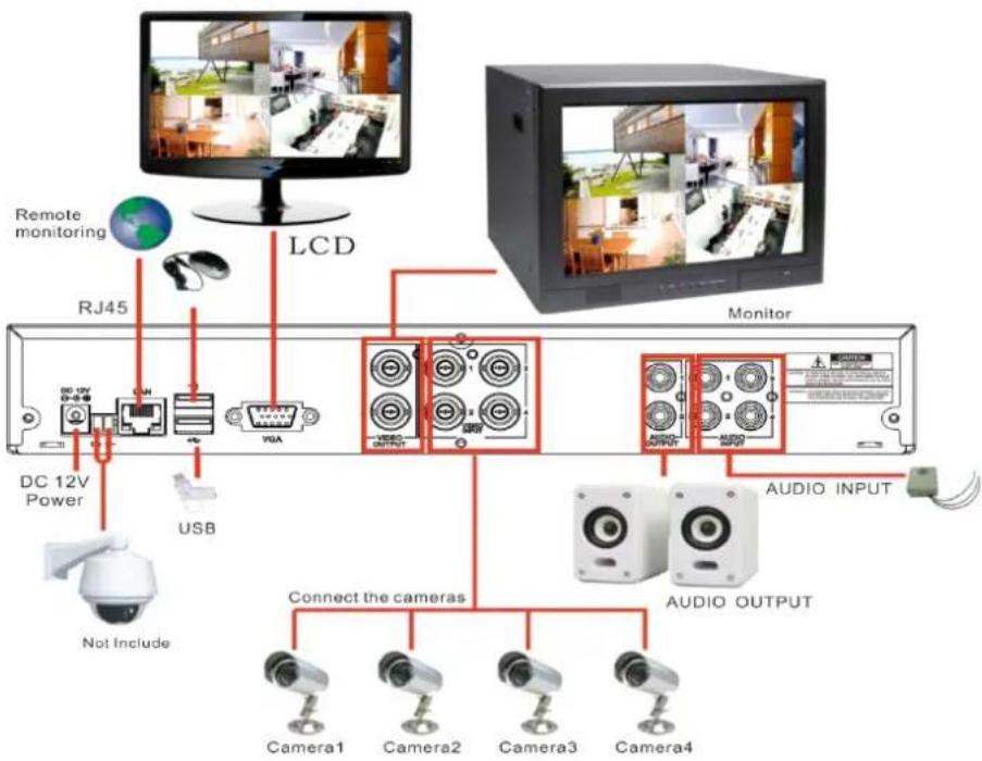
flowchart
graph TD
    A["Remote monitoring"] --> B["LCD"]
    B --> C["Monitor"]
    C --> D["AUDIO INPUT"]
    D --> E["AUDIO OUTPUT"]
    E --> F["Connect the cameras"]
    F --> G["Camera1"]
    F --> H["Camera2"]
    F --> I["Camera3"]
    F --> J["Camera4"]
    K["DC 12V Power"] --> L["USB"]
    M["Not Include"] --> N["Switch"]
    O["RJ45"] --> P["Radio System"]
    Q["LED"] --> R["USB"]
    S["Video"] --> T["Audio Output"]
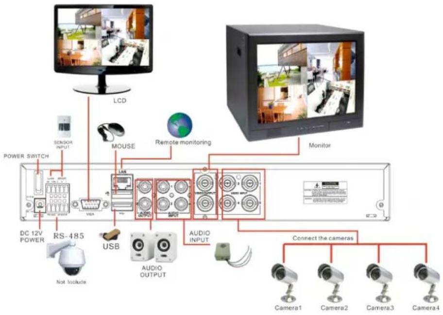
flowchart
graph TD
    A["LCD"] --> B["SENSOR INPUT"]
    B --> C["POWER SWITCH"]
    C --> D["RS-485"]
    D --> E["USB"]
    E --> F["AUDIO OUTPUT"]
    F --> G["Connect the cameras"]
    G --> H["Camera1"]
    G --> I["Camera2"]
    G --> J["Camera3"]
    G --> K["Camera4"]
    L["Mouse"] --> M["Remote monitoring"]
    M --> N["Monitor"]
    O["DC 12V POWER"] --> P["Not Include"]
    Q["Audio INPUT"] --> R["AUDIO OUTPUT"]
    S["Sensor"] --> T["Sensor"]
    U["Monitor"] --> V["Monitor"]
8-CH-CIF
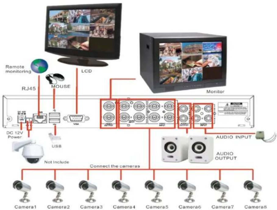
flowchart
graph TD
    A["Camera1"] --> B["Connect the cameras"]
    C["Camera2"] --> B
    D["Camera3"] --> B
    E["Camera4"] --> B
    F["Camera5"] --> G["AUDIO OUTPUT"]
    H["Camera6"] --> G
    I["Camera7"] --> G
    J["Camera8"] --> G
    K["Monitor"] --> L["Remote monitoring"]
    M["Mouse"] --> N["LCD"]
    O["DC 12V Power"] --> P["USB"]
    Q["Not Include"] --> R["Connect the cameras"]
    S["Audio INPUT"] --> T["AUDIO OUTPUT"]
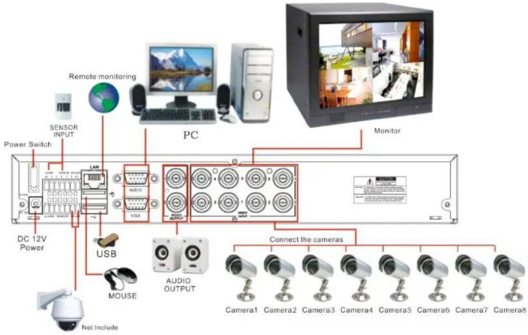
text_image
Remote monitoring SENSOR INPUT Power Switch LAN PC Monitor DC 12V Power USB MOUSE AUDIO OUTPUT Connect the cameras Camera1 Camera2 Camera3 Camera4 Camera5 Camera6 Camera7 Camera8 Not Include8-CH-D1
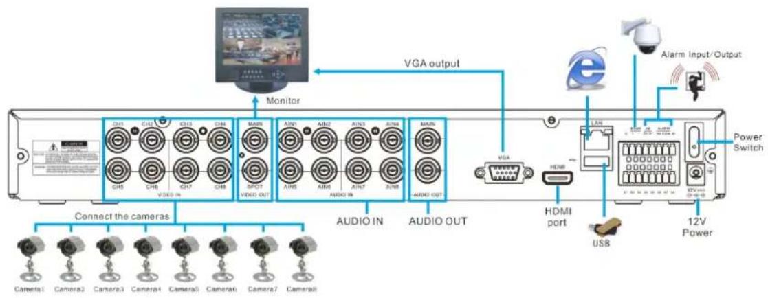
flowchart
graph LR
    A["Camera1"] --> B["Connect the cameras"]
    C["Camera2"] --> B
    D["Camera3"] --> B
    E["Camera4"] --> B
    F["Camera5"] --> B
    G["Camera6"] --> B
    H["Camera7"] --> B
    I["Camera8"] --> B
    J["Video IN"] --> B
    K["Video OUT"] --> B
    L["Audio IN"] --> M["Monitor"]
    N["Audio OUT"] --> O["AUDIO IN"]
    P["VGA output"] --> Q["Monitor"]
    R["HDMI port"] --> S["USB"]
    T["Alarm Input/Output"] --> U["Power Switch"]
    V["12V Power"] --> U
    W["VGA"] --> X["HDMI"]
    Y["12V Power"] --> X
    Z["12V Power"] --> AA["12V Power"]
16-CH CIF
User Manual
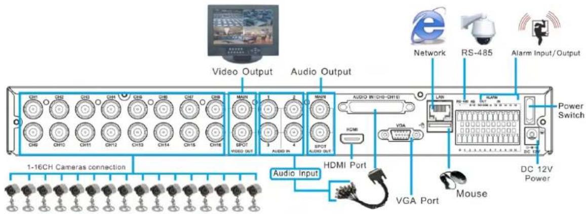
text_image
Video Output Audio Output Network RS-485 Alarm Input/Output CH1 CH2 CH3 CH4 CH5 CH6 CH7 CH8 CH9 CH10 CH11 CH12 CH13 CH14 CH15 CH16 MAIN SPOT VIDEO OUT AUDIO IN AUDIO INT(CHS-CH10) HDMI VGA LAN Power Switch DC 12V Power 1-16CH Cameras connection Audio Input HDMI Port VGA Port Mouse 1-16CH Cameras connection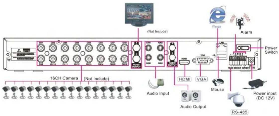
text_image
16CH Camera (Not Include) Audio Input Audio Output HDMI VGA Mouse RS-485 Power input (DC 12V) 16CH VIDEO OUTPUT AUDIO OUTPUT VGA LAN Alarm (Not Include) Rede Power Switch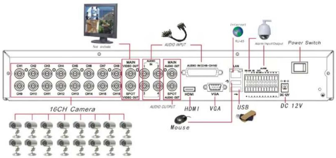
text_image
Not include AUDIO INPUT MAIN VIDEO OUT AUDIO IN MAIN AUDIO OUT AUDIO IN(CHS-CH16) HDMI VGA LAN ALABOR RJ-45 Alarm Input/Output Power Switch 16CH Camera HDMI I VGA USB DC 12V Mouse
text_image
1-16CH Cameras connection Audio Input Audio Output LOOP Port HDMI Port VGA Port RS-232 Port Alarm Output/Input Power Switch Monitor16CH-D1
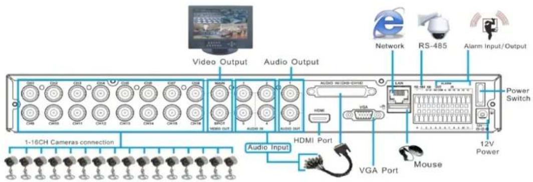
text_image
Video Output Audio Output Network RS-485 Alarm Input/Output 1-16CH Cameras connection Audio Input HDMI Port VGA Port Mouse 12V Power Power Switch7.7 Accessories
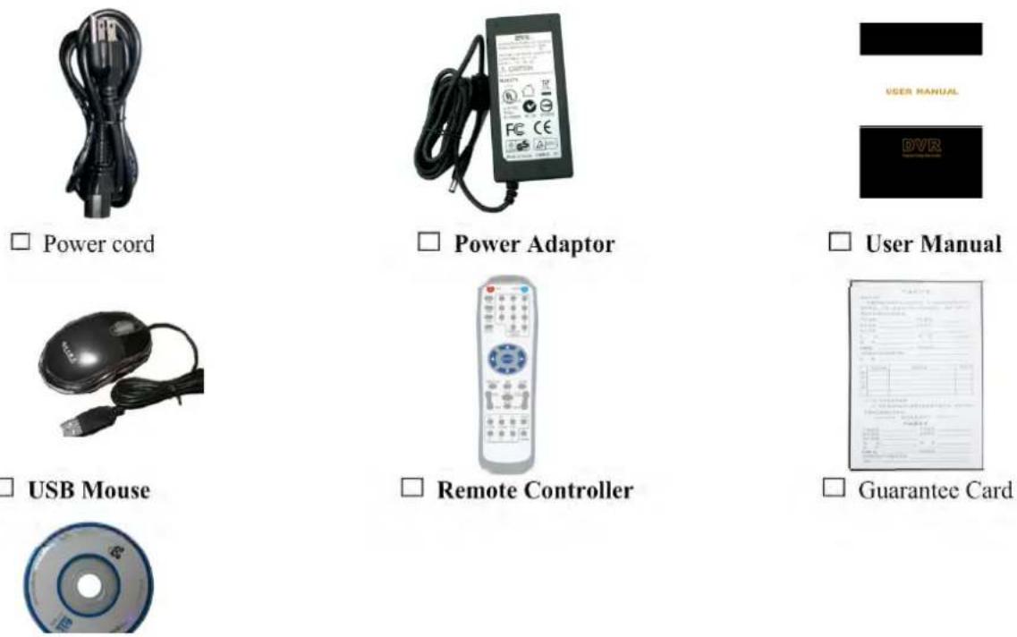
The material in this document is the intellectual property of our department.
No part of this manual may be reproduced, copied, translated, transmitted, or published in any form or by any means without our department prior written permission.
Our products are under continual improvement and we reserve the right to make changes without notice. But no guarantee is given as to the correctness of its contents.
We do not undertake any responsibility for the harms cause by using our product.
The model of the products in the user's manual only for recognition, but these names also perhaps are belong to other company's registered trademark or the copyright.
The product picture may differ from the actual product, only for your reference. The accessories will probably be different according to the different selling areas. For details of accessories, please refer to your local distributor.
Copyright reserved