
ELIP-2036DF - Security Camera Monacor - Free user manual and instructions
Find the device manual for free ELIP-2036DF Monacor in PDF.


| Type | IP Security Camera |
| Model | ELIP-2036DF |
| Brand | Monacor |
| Image Sensor | 2MP (1920x1080) CMOS |
| Lens | Motorized auto focus, 2.8-12mm varifocal |
| Video Compression | H.265 / H.264 |
| Resolution | Up to 1920x1080 @ 30fps |
| Network | RJ45 10/100Mbps Ethernet, PoE (802.3af) |
| Power Supply | 12V DC (optional) or PoE |
| Power Consumption | ≤ 10W |
| Dimensions | Approx. 200 x 70 x 70 mm |
| Weight | Approx. 500 g |
| Weatherproof Rating | IP67 (estimated) |
| Minimum Illumination | 0.01 lux (color), 0 lux with IR |
| IR Distance | Up to 30m (estimated) |
| Audio | Built-in microphone, audio output |
| Alarm I/O | 1 input, 1 output |
| Storage | MicroSD slot (up to 128GB), NFS, NAS |
| Protocols | ONVIF, TCP/IP, HTTP, RTSP, P2P |
| Remote Access | Danale app (iOS/Android) and PC client |
| Motion Detection | Yes, with email/FTP alerts |
| Reset | Factory reset via search tool or hardware button |
| Maintenance | Clean lens with soft dry cloth; avoid solvents |
| Safety | Use only supplied or certified power adapter; ensure proper grounding |
| Compliance | CE, RoHS |
Frequently Asked Questions - ELIP-2036DF Monacor
User questions about ELIP-2036DF Monacor
0 question about this device. Answer the ones you know or ask your own.
Ask a new question about this device
Download the instructions for your Security Camera in PDF format for free! Find your manual ELIP-2036DF - Monacor and take your electronic device back in hand. On this page are published all the documents necessary for the use of your device. ELIP-2036DF by Monacor.
USER MANUAL ELIP-2036DF Monacor
V 4.0
Note:
This manual may contain some incorrect places, even though it was published with our carefully proofreading.
The news updates will be added to the next release without notice. Your valuable advice is really appreciated.
1
Connecting the camera to system
![graph TD A["HD IP Camera (without PoE)"] -->|RJ-45| B["RJ-45 To router LAN port"] C["HD IP Camera (PoE)"] -->|RJ-45| D["To router LAN port"] B --> E["ISP"] D --> E E --> F["Computer"] G["PoE NVR"] --> H["To NVR PoE port"] I["HD Monitor"] --> J["HDMI or VGA output"] K["RFID"] --> L["RFID Port"] M["RF…](/content/2026/05/804949/images/4d59a996c123cf77781af6c26d60ae926b84ca96696aec0fd2b0f8e0b4e594ec.jpg)
Figure 1: Working With POE Switch
![graph TD A["HD IP Camera (without PoE)"] -->|RJ-45| B["TO Switch or Router LAN port"] C["HD IP Camera (PoE)"] -->|RJ-45| D["TO PoE Switch LAN port"] B --> E["POE Ethernet Switch"] D --> E E --> F["Router"] F --> G["To switch or Router LAN port"] G --> H["Power Adaptor"] G --> I["HDMI or VGA output"]…](/content/2026/05/804949/images/6bf83a55c3f7beb60d61afb3c086560fb97297d167f1d05c7635a42cca8dbe1d.jpg)
Figure 2: Working With POE NVR
Note:
- The camera should be connected to an OPTIONAL 12 volt power supply if you do not use PoE (Power over Ethernet).
- A Windows computer is more convenient to setup and troubleshooting.
Modifying the camera's IP address
Default: IP address: 192.168.0.123, Username: admin, Password: 123456
( We strongly recommend modifying the default password for your security).
Each IP camera has the same default IP address after leaving the factory. In order to guarantee network connectivity and access the live video, it is essential to change the camera's IP address to unique via computer before using. To quickly configure the IP camera, download the device search tool from the Internet: www.monacor.com -> Support -> Downloads.
Before modifying the IP address you'd better confirm the IP network planning and avoid IP address conflict.
Steps on Local Area Windows 10 PC : Search Windows -> cmd -> ipconfig /all
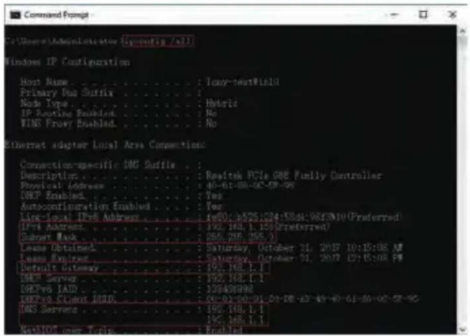
Now you can get all the local network information.
IPv4 Address: 192.168.1.?
Subnet Mask: 255.255.255.0
Default gateway: 192.168.1.1
DNS Servers: 192.168.1.1
Note : You can also find out the LAN configuration via Windows GUI
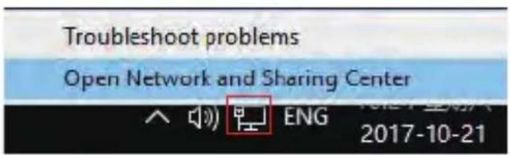
Right-click on the Network icon and select open Network and Sharing Center.
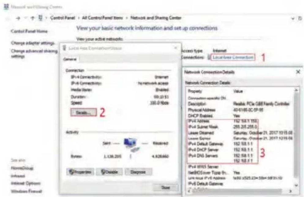
If the camera is installed to work with the local switch or router directly, the camera IP range should be 192.168.1.x (x=2-254). To void IP conflict, you should test and select an unoccupied IP like this:
Command Prompt ping test
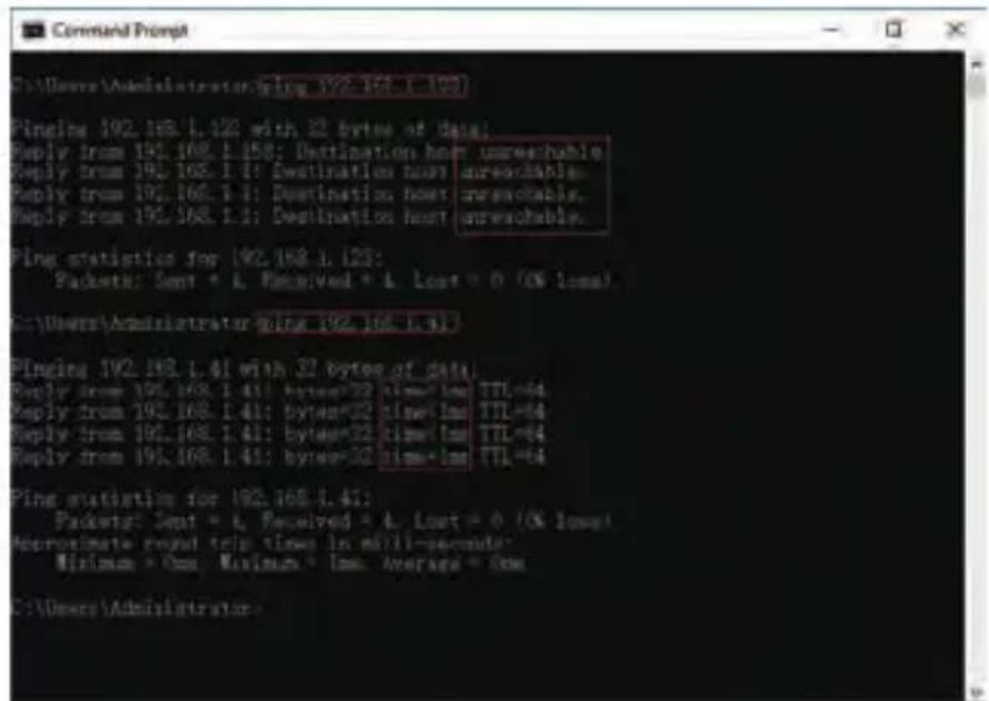
Only when reply unreachable that means the IP address is no conflict and available, otherwise when you see time reply do not use this IP address.
There are three methods to modify the camera IP configuration, Search tool, UC Client software and Internet Explorer.
Using Device Search Tool
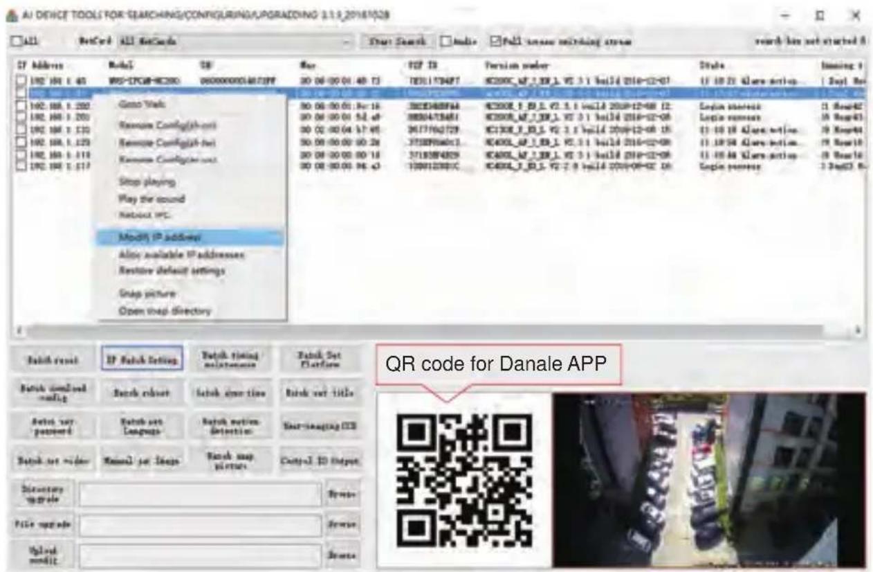
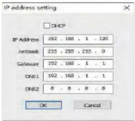
a. Click Start Search and all your cameras in the LAN will be listed. Modify IP address to suit the LAN's IP scheme. There are two modifying methods available: 1) Right click on the desired camera and choose "Modify IP address". 2) Click the ALL check-box then click "IP Batch Setting".
b. You can also enable the camera DHCP function if there is a DHCP server available in the LAN.
Most router has DHCP server built-in. (IP address in DHCP setting may change after device restart. We do not recommend leaving the IP camera on DHCP).
Tips:
Reset Password -> Restore default settings;
Video full-screen -> double-click video;
Firmware upgrade -> Select the check-box, click Browse then click File Upgrade.
(Default user name: admin, Password: 123456)
-
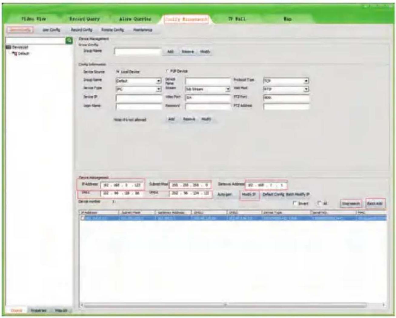
Go to the Devices Config and click Start search, all the camera in the LAN will be listed. Highlighting one of the camera will populate the filed above. Change the parameter listed in the field and click on "Modify IP" to modify the camera's IP address. Please modify the default IP address to match your LAN's IP scheme. Note: Be careful when setting up IP addresses to not have duplicated IP as other devices in LAN.
-
After changing all the IP cameras' IP address, you can search again and add them all to the UC client. Once the cameras are added, go to the tab Video View and drag the camera into the split windows to start previewing the cameras.
4
Working with Internet Explorer
To access the camera's web interface, type in the IP camera's IP address in Internet Explorer's URL bar to gain access to the login page. Please modify IP address to the same subnet if login page can not load.
(Default user name: admin, Password: 123456); only IE is supported.
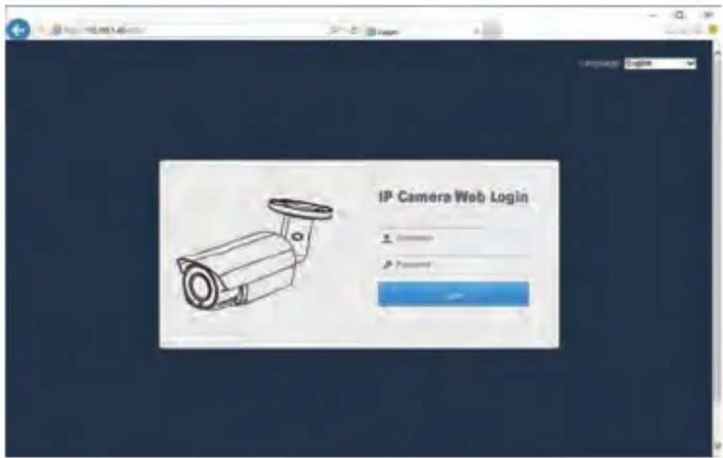
From the login page, select your familiar language, then log in with the username and password.
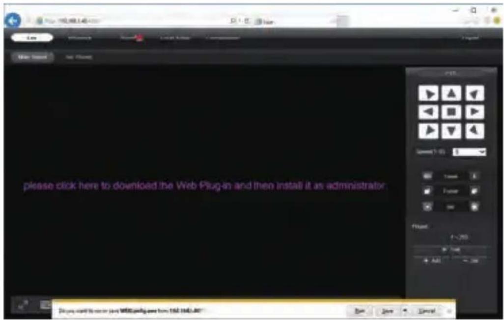
Working with Internet Explorer
Install Web Plug-in when red line characters prompted. You may have to download WEBConfig.exe and run it as administrator. After installation, restart or refresh your web browser and access the IP again. The live video will start automatically after login successfully.
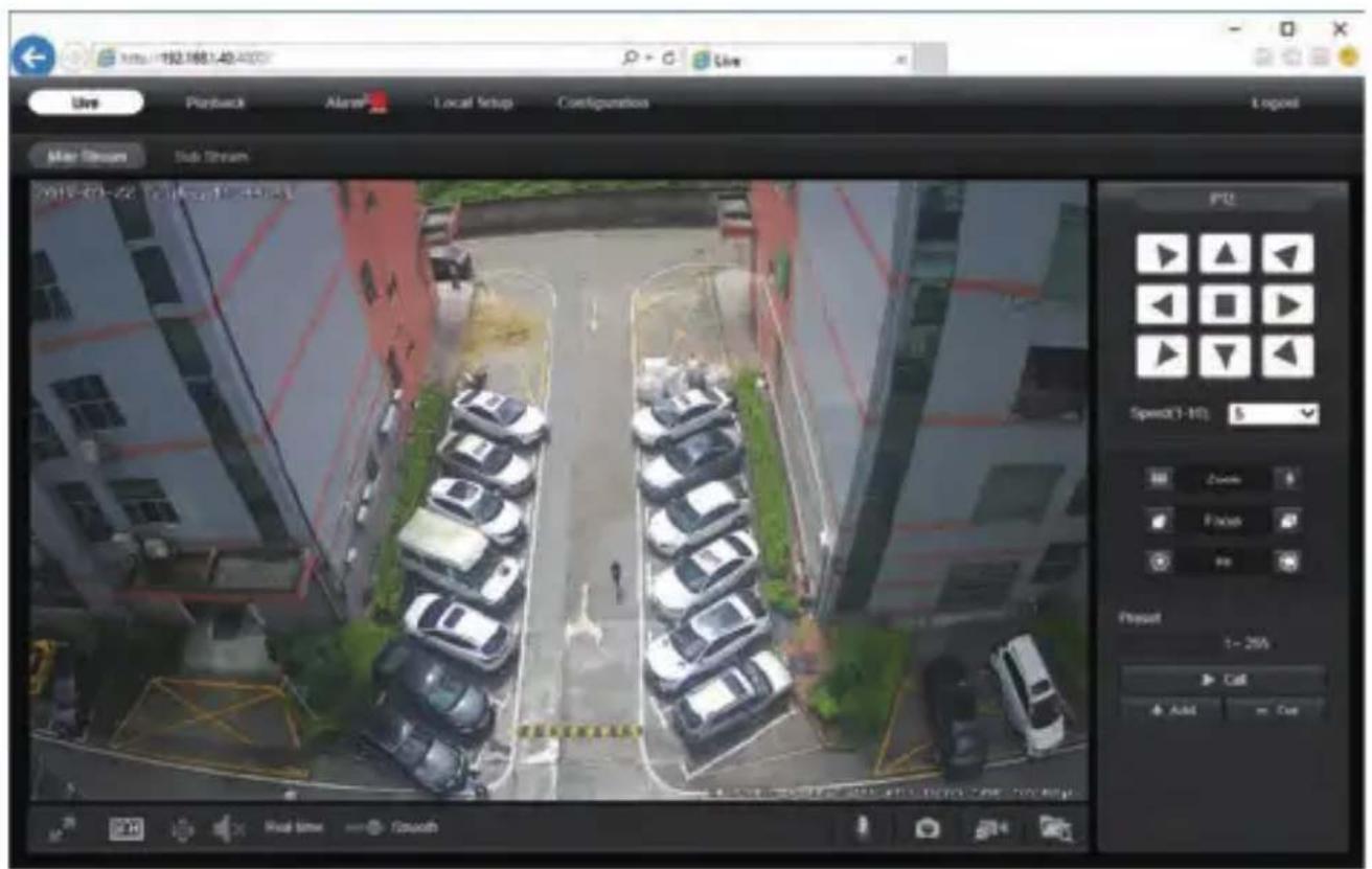
Note: Only the Motorized Auto Focus cameras can Zoom In and Zoom Out. Keeping pressing on live video and dragging for Digital Zoom.
If there is a delay in video response when accessing remotely, please switch to Sub Stream instead. To learn the function of each button, just put the mouse on, it will show screen tips.
5
General Configurations
1) Power System frequency configuration (50Hz/60Hz)
Configuration > Camera > Image > Power Frequency
To avoid the video flicker, the camera should be set to right working frequency to suit the country electric system. The countries that use 60Hz have USA, Canada, Japan, Korea, Taiwan, Brazil, Philippines, Mexico. Other countries apply 50Hz.
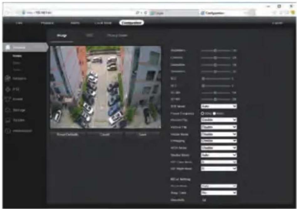
2) To modify the camera Title name and Time & Date
Configuration > Camera > Image > OSD > Title Message
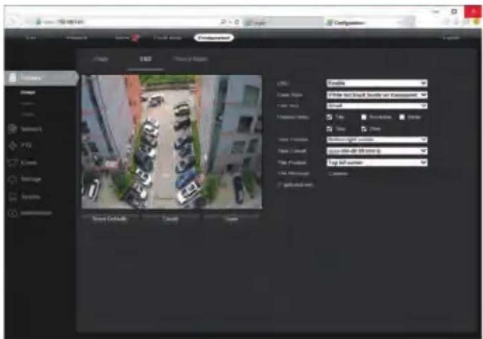
There are two time update modes available, Manual and NTP.
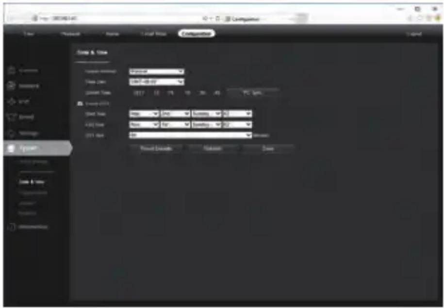
a. Select your Time Zone, and click PC Sync. Set up your DST (Daylight Savings Time) if needed, click Save. (Time and date will be set 2000-01-01 if the camera is reset.)
b. If the camera is connected to the Internet, you can set up a NTP server for the camera to sync the time and date automatically.
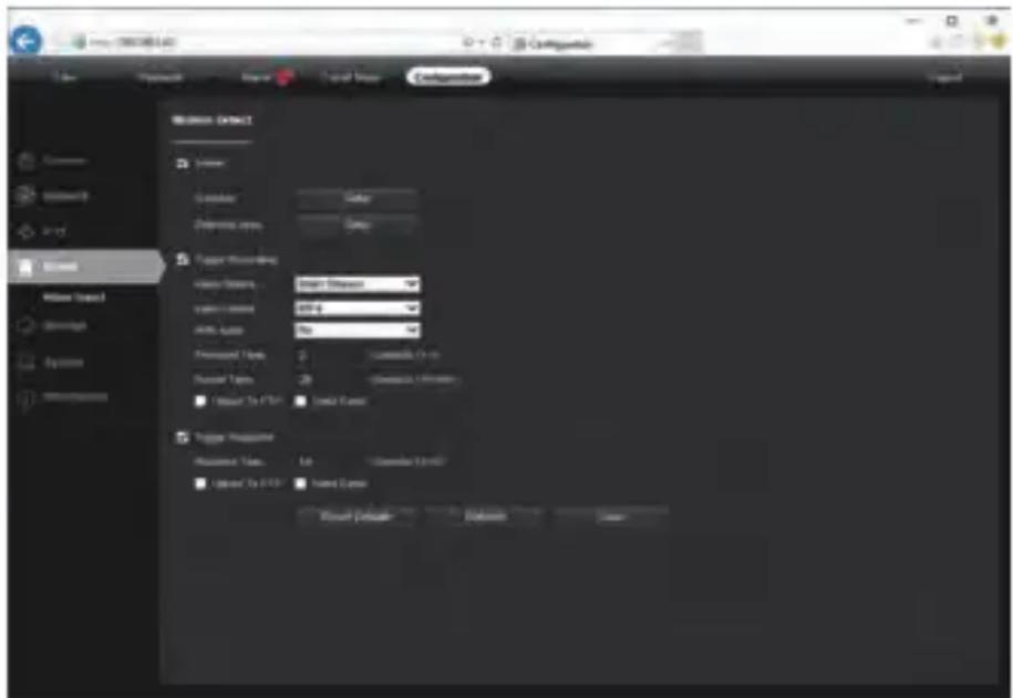
3) To enable Motion Detection Alarm
Configuration > Event > Video Detection
5
General Configurations
When Motion is detected, there is a small alarm light pup up beside the Alarm menu. You can also setup an email address or FTP storage server to receive the motion snapshot. (Trigger recording will work only if memory card or NFS NAS connected.)
4) To find the device Cloud ID and QR code for p2p remote access
Configuration > Network > P2P
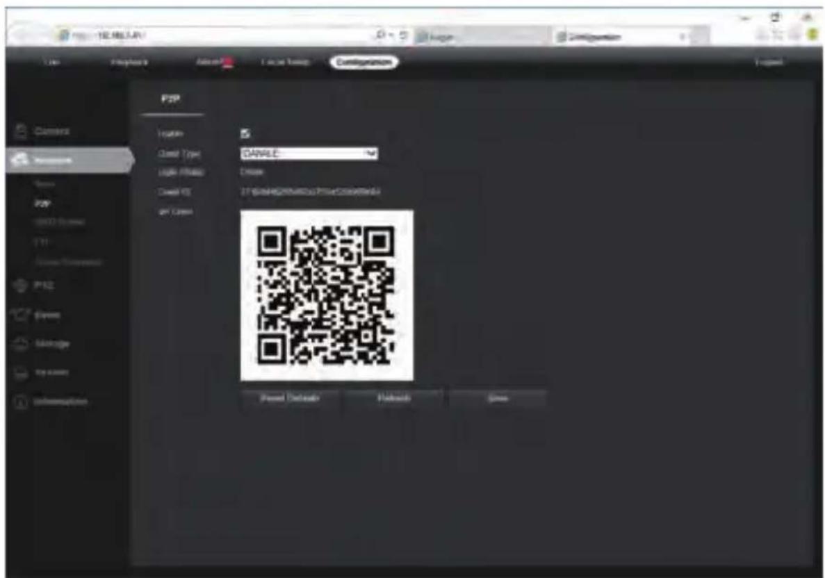
Using the P2P ID and QR code, you can access the camera remotely anywhere via smart phone with Internet access. Please register an account via mobile phone after installing the Danale APP from APP Store or Google Play Market, then log in and add your camera to start previewing.
Or you can go to the website http://www.danale.com/ to register if you need PC remote access. You can download APP from the website to find out more.
Tips: if the Login Status shows Offline, please check your network connection and IP camera TCP/IP Network configurations. Please make sure to use a valid DNS server IP in the TCP/IP Network setting.
6
Working with mobile device
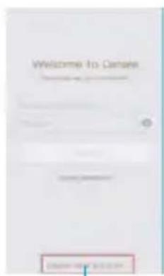
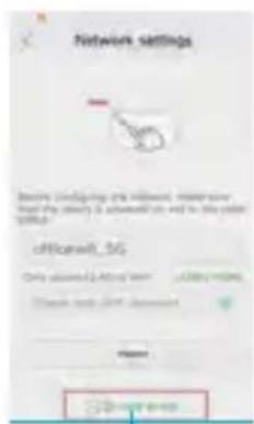
Visit the Apple App Store or the Google Play Store to download the Danale app for iOS or Android devices. (For transferring the file manually to your smart device, please refer to your smart device's manual). After installation, tap the icon to launch the Danale app. For first time use, please create a new account by following the steps below:
1

2

③

4
5
6

7
-
For new users, please tap CREATE NEW ACCOUNT to register an account.
-
Type in your mobile phone number or email address, then tap NEXT.
-
Check your SMS or Email for the verification code, then tap NEXT.
-
Tap + to Add devices
-
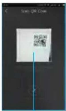
Tap QR Code to add to get into the scan camera QR code page, or click NEXT to discover the connected local LAN IP camera.
-
Put the IP camera QR code in the app effective scan area, and then give a nickname for the recognized camera.
-
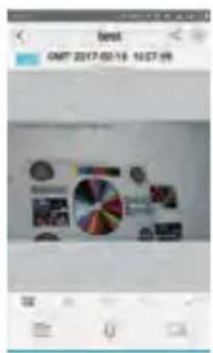
Tap the camera list to start live video.
Tips: a. Tap ≡ to check your account profile and configure settings.
b. To share your camera with your friends or another user, click “◀” icon and type in or scan his/her Danale account.
Note: If you cannot connect the camera, please check your Internet connection and verify the IP address, gateway, and DNS setting in the camera. The Cloud login status should be online, which means the camera has registered to the cloud server. You may also want to connect your phone to WiFi for better performance.
The app is offered free of charge by a third party; it is not covered by the warranty of MONACOR International. Charges may apply for some of the Cloud services available as options in the app! If problems occur, please contact the provider of the app.
7
Working with NVR
The IP camera supports standard ONVIF protocol and it can be added to third-party video recorder. Some of the models support both H.264 and H.265 encode mode. The H.265 encode cameras can compress the video data to a very low bit rates which allows more video data storage than normal H.264 camera. Only configure the camera to H.265 mode when your NVR supports H.265 mode
Before pairing cameras to the NVR, make sure the NVR and cameras have valid and matching IP scheme.
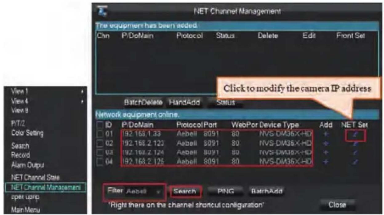
Note: Some of the PoE NVR supports Plug & play, which allows you to get video without manually search and add. if Plug & play feature is not available or not compatible, please follow the NVR manual steps and select ONVIF protocol as the paring protocol. (camera default password: 123456)
If the POE NVR can not discover the connected camera or can not display the camera video, please check it's internal POE interface IP configuration and make sure all connected cameras and NVR POE interface are in the same subnet schema. For more help please contact the both NVR and IP camera suppliers for technical assistance.
8
Frequently Asked Questions
- Why can't I open the default IP address 192.168.0.123 via web browser?
Check your computer's IP address before accessing the camera. If the IP address does not match the 192.168.0.x scheme, please download the device search tool from the Internet (www.monacor.com -> Support -> Downloads) to modify the camera's IP address. Make sure the IP address of the camera matches the LAN IP scheme. For example, if the LAN is 192.168.1.xxx, then set the IP camera to 192.168.1.123 and so on. Only IE windows computer is supported by the camera.
- How to reset the password?
The default Username: admin, Password: 123456. If you lost the password or would to reset the camera's setting, please install the search tool to search the camera IP and click Reset factory button.
- How to upgrade the IP camera?
1) Ask the supplier for the suitable firmware
2) you can use the web browser, search tool, or PC client to upgrade the camera.
3) go to the Configuration > System > update, click browse and select the firmware, then click Upgrade button and wait for the operation to complete.
- How to fetch the RTSP video stream and http snapshot?
1) Main Stream: rtsp://IP:554/h264?username=admin&password=123456
2) Sub Stream: rtsp://IP:554/h264cif?username=admin&password=123456
3) Low resolution snapshot: http://IP/cgi-bin/snapshot.cgi?stream=1
4) HD snapshot : http://IP/cgi-bin/snapshot.cgi?stream=0
- Why does the NVR not show image after adding your IP camera?
1) Make sure you selected the right protocol and enter the correct username and password when adding the cameras,
2) Make sure the NVR and IP camera are the same IP scheme.(eg. NVR:192.168.1.x, and IP camera:192.168.1.y),
3) try changing the camera encode mode to H.264 if the NVR can't support H.265.
(Configuration -> Camera -> Video > Encode mode: H.264)
- How to make the NVR record in motion detection mode?
1) Enable the IP camera motion detection function via web browser or Search configure tool,
2) activate the record mode for motion detection in the schedule of the recorder,
3) check the NVR screen MD icon and try playback. Please refer to your NVR manual for NVR motion record option.
- Where can I control the motorized auto focus lens zoom?
1) Using the camera's web interface;
2) Control by PC client software UC;
3) Roll the mouse wheel at the search tool preview window;
4) Find the PTZ menu in your NVR to control lens zoom.




- 1
- CONNECTING THE CAMERA TO SYSTEM
- NOTE
- MODIFYING THE CAMERA'S IP ADDRESS
- DEFAULT: IP ADDRESS: 192.168.0.123, USERNAME: ADMIN, PASSWORD: 123456
- NOW YOU CAN GET ALL THE LOCAL NETWORK INFORMATION
- USING DEVICE SEARCH TOOL
- TIPS
- 4
- WORKING WITH INTERNET EXPLORER
- 5
- GENERAL CONFIGURATIONS
- CONFIGURATION > EVENT > VIDEO DETECTION
- 6
- WORKING WITH MOBILE DEVICE
- 7
- WORKING WITH NVR
- 8
- FREQUENTLY ASKED QUESTIONS
Brand : Monacor
Model : ELIP-2036DF
Category : Security Camera