
DMR-508 - Security Camera Monacor - Free user manual and instructions
Find the device manual for free DMR-508 Monacor in PDF.


| Product Type | Digital Video Recorder (DVR) |
| Brand / Model | Monacor DMR-508 |
| Video Compression | MPEG4 |
| Video Inputs | 8 channels (BNC, 1 Vp-p 75 Ω) |
| Video Outputs | Main monitor (BNC), Call monitor (BNC) |
| Audio Input / Output | 4 inputs (mono) / 2 outputs (mono) |
| Max Recording Rate (Frame) | 60 IPS (NTSC) / 50 IPS (PAL) |
| Max Recording Rate (CIF) | 240 IPS (NTSC) / 200 IPS (PAL) |
| Recording Modes | Manual, Timer, Motion, Alarm |
| Hard Disk Support | Up to 2 IDE HDDs (ATA66, >400 GB each) |
| Backup Methods | USB 2.0, DVD-RW/CD-RW (optional), Network |
| Network Interface | Ethernet 10/100 Base-T, TCP/IP, PPPoE, DHCP, DDNS |
| Remote Surveillance | GPRS (mobile), Web browser, Licensed software AP |
| PTZ Control | RS-485, PELCO-D protocol |
| Motion Detection | 16 × 12 grids per camera, 4 adjustable sensitivities |
| Pre-alarm Recording | 8 MB |
| Alarm I/O | 8 inputs / 1 output |
| Dimensions (W × H × D) | 432 × 90 × 326 mm |
| Power Supply | DC 19V |
| Power Consumption | < 64 W |
| Operating Temperature | 10°C – 40°C (50°F – 104°F) |
| System Recovery | Auto after power reconnection |
| Watermark / Covert Recording | Yes / Yes (mask live view) |
| Digital Zoom | 2X |
| Safety Precautions | Avoid moisture, use only specified power adapter |
| Maintenance / Cleaning | Wipe with dry cloth; no liquid cleaners |
| Spare Parts / Repairability | User-replaceable HDD; optional IR remote, VGA card |
Frequently Asked Questions - DMR-508 Monacor
User questions about DMR-508 Monacor
0 question about this device. Answer the ones you know or ask your own.
Ask a new question about this device
Download the instructions for your Security Camera in PDF format for free! Find your manual DMR-508 - Monacor and take your electronic device back in hand. On this page are published all the documents necessary for the use of your device. DMR-508 by Monacor.
USER MANUAL DMR-508 Monacor
Real time performance 30IPS (N) / 25IPS (P) per channel
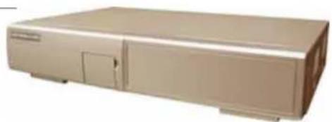
DMR - 504
natural_image
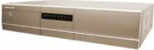
Exterior view of a beige rectangular electronic device with ventilation slots and control panel (no visible text or symbols)DMR - 508 / 516
natural_image
Exterior view of a beige industrial electronic device with a control panel (no visible text or symbols)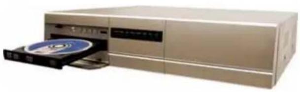
natural_image
Exterior view of a beige electronic device with an open CD or DVD drive (no visible text or symbols)User's Manual
Please read instructions thoroughly before operation and retain it for future reference.
MPEG4 DVR SERIES_V0.989

CAUTION
RISK OF ELECTRIC SHOCK

CAUTION:
To reduce the risk of electric shock, do not expose this apparatus to rain or moisture.
Only operate this apparatus from the type of power source indicated on the label.
The lightning flash with arrowhead symbol, within an equilateral triangle, is intended to alert the user to the presence of uninsulated “dangerous voltage” within the product’s enclosure that may be of sufficient magnitude to constitute a risk of electric shock to persons.

This exclamation point within an equilateral triangle is intended to alert the user to the presence of important operating and maintenance (servicing) instructions in the literature accompanying the appliance.

CE Mark
This apparatus is manufactured to comply with the radio interference requirements.

THIS PRODUCT IS LICENSED UNDER THE MPEG-4 VISUAL PATENT PORTFOLIO LICENSE FOR THE PERSONAL AND NON-COMMERCIAL USE OF A CONSUMER FOR (i) ENCODING VIDEO IN COMPLIANCE WITH THE MPEG-4 VISUAL STANDARD ("MPEG-4 VIDEO") AND/OR (ii) DECODING MPEG-4 VIDEO THAT WAS ENCODED BY A CONSUMER ENGAGED IN A PERSONAL AND NON-COMMERCIAL ACTIVITY AND/OR WAS OBTAINED FROM A VIDEO PROVIDER LICENSED BY MPEG LA TO PROVIDE MPEG-4 VIDEO. NO LICENSE IS GRANTED OR SHALL BE IMPLIED FOR ANY OTHER USE. ADDITIONAL INFORMATION INCLUDING THAT RELATING TO PROMOTIONAL INTERNAL AND COMMERCIAL USES AND LICENSING MAY BE OBTAINED FROM MPEG LA, LLC. SEE HTTP://WWW.MPEGLA.COM.
TABLE OF CONTENTS
PARTS AND FEATURES
1.1 FEATURES 1
1.2 PACKAGE CONTENTS 1
1.3 SPECIFICATION 2
1.4 FRONT PANEL 4
1.5 REAR PANEL 8
GETTING STARTED
2.1 GETTING STARTED 10
BASIC OPERATION
AP ADVANCED SETTING 37
Network 37
DDNS 38
MAIL 39
FTP 39
DVR-CAMERA SETTING 40
DEVICE 40
DETECTION 41
NETWORK BACKUP & PLAYBACK 42
ALARM 43
ALARM LIST 43
GENERAL 44
ACCOUNT 44
ONLINE USER INFO 45
FILE PATH 45
5.7 CONNECT TO AP VIA IE BROWSER 46
5.8 GPRS 47
5.9 OPTIONAL PHERIPHERALS 47
TROUBLE SHOOTING
6.1 FAQ 48
APPENDIX #1 INSTALL THE HDD 49
APPENDIX #2 PIN CONFIGURATION 51
APPENDIX #3 RS232 PROTOCOL 53
APPENDIX #3 RECORDING TIME TABLE 54
APPENDIX #4 COMPATIBLE USB BRAND 55
APPENDIX #5 COMPATIBLE HDD BRAND 56
1.1 FEATURES
MPEG4 DVR Technology
- Compression format provides crystal clear image with real time performance
Multiplex
- Allows live display, record, playback, backup, and network all at the same time
Long-Recording Hours:
- 500GB can record more than 4 days. (16CH, Frame Best Quality, 120IPS)
- Connect to Independent Disk Array (optional) to have more storage capacity
Backup Function:
Backup files with USB interface, DVD-WRITER or CD-WRITER and network remote recording & backup
Remote Surveillance:
GPRS allows viewing and controlling of the system & also support remote surveillance with licensed software AP and IE browser Web surveillance supports 5 users simultaneously
Intelligent Motion Trigger Recording:
With advanced motion detection function, scheduled motion detection recording (4 different adjustable factors for motion detection sensitivity) and convenient search function, customized security environment is achieved
- Alarm trigger recording will send alert with images to designated e-mail and FTP address
● Supports pre-alarm recording (8MB)
Covert Recording:
A mask replaces the live image with a blank screen & the monitor shows nothing but recording is still on
A/V Support:
● Supports 4 audio-in, 2 audio-out to record sounds
● Supports VGA output to monitor (optional)
General:
Support multi-language OSD
- System auto recovery after power reconnected
- IR remote control of the system and PTZ through RS-485
- Support daylight saving function
- Support manual / timer / motion / alarm / remote recording functions
Watermark function ensures authentication of recorded images
- Support TCP/IP, PPPoE, DHCP and DDNS network connection
1.2 PACKAGE CONTENTS
| 4CH8CH16 | 6CH10DBE8CH / 4CH DVD-RW / CD-RW | |||
| Digital Video Recorder | √ √ √ √ | |||
| Adapter | √ √ √ √ | |||
| Licensed Software AP | √ √ √ √ | |||
| IR Transmitter and IR Receiver | √ | √ | Optional | √ |
| Power and Data Bus | √ √ √ √ | |||
| DSUB PIN Connector | √ √ √ √ | |||
| Screws | √ √ √ √ |
NOTE: Please check the package contents to make sure that you receive all accessories shown above.
1.3 SPECIFICATION
| MODEL | DMR - 516 | DMR - 508 | DMR - 504 |
| Video System | NTSC / PAL (switch able) | ||
| Video Compression Format | MPEG 4 | ||
| Video Input(Composite video signal 1 Vp-p 75Ω BNC) | 16 Channels | 8 Channels | 4 Channels |
| Video Loop Out(Composite video signal 1 Vp-p 75Ω BNC) | 16 Channels | 8 Channels | 4 Channels |
| Video Output | Main Monitor Output:Composite video signal 1 Vp-p 75Ω BNCCall Monitor Output:Composite video signal 1 Vp-p 75Ω BNC | ||
| Maximum Recording Rate (Frame) | 720 × 480 pixels with 120 IPS( NTSC)720 × 576 pixels with 100 IPS( PAL) | 720 × 480 pixels with 60 IPS( NTSC)720 × 576 pixels with 50 IPS( PAL) | 720 × 480 pixels with 30 IPS( NTSC)720 × 576 pixels with 25 IPS( PAL) |
| Maximum Recording Rate (CIF) | 352 × 240 pixels with 480 IPS( NTSC)352 × 288 pixels with 400 IPS( PAL) | 352 × 240 pixels with 240 IPS( NTSC)352 × 288 pixels with 200 IPS( PAL) | 352 × 240 pixels with 120 IPS( NTSC)352 × 288 pixels with 100 IPS( PAL) |
| Adjustable Recording Speed (Frame) | 120, 60, 30, 15 IPS100, 50, 25, 12 IPS | 60, 30, 15, 7 IPS50, 25, 12, 6 IPS | 30, 15, 7, 3 IPS25, 12, 6, 3 IPS |
| Adjustable Recording Speed (CIF) | 480, 240, 120, 60 IPS400, 200, 100, 50 IPS | 240, 120, 60, 30 IPS200, 100, 50, 25 IPS | 120, 60, 30, 15 IPS100, 50, 25, 12 IPS |
| Image Quality Setting | Best, High, Normal, and Basic | ||
| Hard Disk Storage(IDE type, ATA66) (over 400GB) | 16CH: support HDD * 216CH (D): support HDD *1 | 8CH: support HDD * 28CH (D): support HDD *1 | 4CH: support HDD * 14CH (D): support HDD *1 |
| HDD Quick Cleaning | Quick clean up the "index system" of the recorded files. 250GB under 2 seconds | ||
| Recording Mode | Manual/ Timer/ Motion/ Alarm | ||
| Watermark | Yes | ||
| Refresh Rate | 480 IPS for NTSC400 IPS for PAL | 240 IPS for NTSC200 IPS for PAL | 120 IPS for NTSC100 IPS for PAL |
| Multiplex Operation | live display, record, playback, backup, and network | ||
| Audio I/O | 4 audio inputs, 2 audio outputs (Mono) | ||
| Motion Detection Area | 16 × 12 grids per camera for all channels | ||
| Motion Detect Sensitivity | 4 adjustable variables with precise calculation for motion detection | ||
| Pre-alarm Recording | Yes (8 MB) | ||
| Backup Device | USB1.1 / 2.0 backup and network remote backup | ||
| front panel * 1front panel * | |||
| Motion JPEGWeb Transmitting Compression Format | |||
| 10/100 Base-T. Support remote control and live view via EthernetEthernet | |||
| Mobile Surveillance | Support GPRS to access the system via mobile phone (require J2ME, MIDP2.0 protocol) | ||
| Support licensed software AP, and IE browserWeb Interface | |||
| Remote Alarm Notification | E-mail images, and images uploading to FTP site's specific account | ||
| TCP/IP, PPPoE, DHCP and DDNSNetwork Protocol | |||
| IR transmitter | Remote control DVR and PTZ via IR transmitter (RS-485) (4CH: Optional) | ||
| Support PELCO-D protocolPTZ control | |||
| Dwell Time (Sequential Channel Switch) | Programmable with adjustable dwell time (2, 4, 8, 16 sec.) | ||
| 16 inputs, 1 outputAlarm I/O | 8 inputs, 1 output 4 inputs, | output | |
| Picture Zoom | Support 2X digital zoom function | ||
| YesKey Lock | |||
| YesVideo Loss Detection | |||
| Specification Continued ... | |||
| Camera Title | Support up to 6 letter | ||
| Video Adjustable | Hue/ Color/ Contrast/ Brightness | ||
| Date Display Format | YY/MM/DD, DD/MM/YY, MM/DD/YY, and Off | ||
| Daylight Saving | Yes | ||
| Power Source | DC 19V | ||
| < 64 WPower Consumption | 4CH: < 42 W ; 4CH (D): < 64 W | ||
| Operating Temperature | 10°C ~ 40°C (50°F~104°F) | ||
| Dimensions (mm) | 432mm (W) × 90mm (H) × 326mm (D) | 432mm (W) × 90mm (H) × 326mm (D) | |
| System Recovery | System auto recovery after power reconnected | ||
| Optional Peripherals | Independent Disk Array ; VGA Connector | Independent Disk Array ; VGA Connector ; IR Remote Control | |
16CH / 16CH(D)
| Total IPS | 120 | 60 | 30 | 15 | |
| Frame | Best | 109 | 192 | 349 | 565 |
| High | 138 | 243 | 442 | 714 | |
| Normal | 182 | 319 | 581 | 939 | |
| Basic | 293 | 516 | 939 | 1517 | |
| Total IPS | 480 | 240 | 120 | 60 | |
| CIF | Best | 130 | 229 | 417 | 673 |
| High | 184 | 323 | 587 | 949 | |
| Normal | 242 | 424 | 773 | 1249 | |
| Basic | 335 | 588 | 1071 | 1730 | |
8CH | 8CH(D)
| Total IPS | 60 | 30 | 15 | 7 | |
| Frame | Best | 218 | 384 | 689 | 1130 |
| High | 276 | 486 | 882 | 1428 | |
| Normal | 364 | 638 | 1162 | 1878 | |
| Basic | 586 | 1032 | 1878 | 3034 | |
| Total IPS | 240 | 120 | 60 | 30 | |
| CIF | Best | 260 | 458 | 834 | 1346 |
| High | 368 | 646 | 1174 | 1898 | |
| Normal | 484 | 848 | 1546 | 2498 | |
| Basic | 670 | 1176 | 2142 | 3460 | |
4CH | 4CH(D)
| Total IPS | 30 | 15 | 7 | 3 | |
| Frame | Best | 436 | 767 | 1398 | 2260 |
| High | 552 | 972 | 1764 | 2856 | |
| Normal | 728 | 1276 | 2324 | 3756 | |
| Basic | 1172 | 2064 | 3756 | 6068 | |
| Total IPS | 120 | 60 | 30 | 15 | |
| CIF | Best | 520 | 916 | 1668 | 2692 |
| High | 736 | 1292 | 2348 | 3796 | |
| Normal | 968 | 1696 | 3092 | 4996 | |
| Basic | 1340 | 2352 | 4284 | 6920 | |
※ 1. For 500GB HDD record time (hour) 2. Take outdoor environment as example
☐ Any changes made to the actual product are subjects to no further notification.
1.4 FRONT PANEL
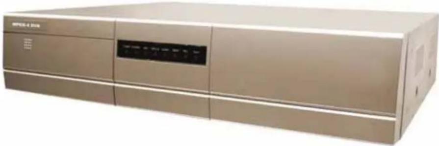
DMR - 516 / 508
16CH (D) / 8CH (D) / 4CH (D)
natural_image
Exterior view of a beige industrial electronic device (no visible text or symbols)1) POWER:
Press "POWER" button to turn on/ turn off the DVR.
(Under recording mode, please stop record before turn off the DVR)
2) MENU:
Press "MENU" button to enter main menu.
3) ENTER / RECORD:
Press "ENTER" button to confirm.
Press "RECORD" to activate the manual recording.
4) “+ ““ - ”:
Press “ + “ or “ - ” button to change the setting in the menu / to select the channel.
Press “+” and “-” buttons to open / close the DVD / CD WRITER.
5) USB:
Support firmware update and files backup.
6) LED LIGHT:
POWER: Power on
STANDBY: Standby
HDD: HDD is reading or recording
HDD Full: HDD is full.
ALARM: Once the alarm is triggered
TIMER: When timer recording is turned on.
REC: Under recording status
PLAY: Under playing status
7) MODE

Press "MODE " button to switch channel display mode.
8) “ ”:
Press "button to pause the play back files.
9) “ ”: ■
Press “” button to stop the play back files.
10) “.”
Under playback mode, press " " button to fast rewind.
11) “:
Under playback mode, press “” to fast forward.
12) "ZOOM":
Press "ZOOM" button to enlarge the picture of selected channel (2X digital zoom).
13) "PLAY":
Press "PLAY" button to playback recorded files.
14) “▲▼◀▶”:
Press “▲▼◀▶” to move the cursor up / down / left / right.
15) "SHIFT" + "SEQ":
Press “SHIFT” + “SEQ” to activate the call monitor function and press “SEQ” to escape the call monitor mode.
16) "SHIFT" + "AUDIO":
Press "SHIFT" + "AUDIO" to select live or playback sounds of the 4 audio channels.
17) "SHIFT" + "SLOW":
Under playback mode, press "SHIFT" + "SLOW" to show slow playback.
18) “SHIFT” + “CH - “ or “CH + ” :
Press “SHIFT” + “CH - “ or “CH + ” change the setting in the menu / to select the channel.
19) "SHIFT" + "SET":
Press "SHIFT" + "SET" to change channel display position.
Press “▲▼◀▶” to select the channel which You would like to change,
Press “+” or “-” select the channel which You would like to show.
Press "ENTER" button to confirm.
20) "SHIFT" + "SEARCH":
Press "SHIFT" + "SEARCH" buttons to enter the search mode.
21) “” + :
Press “◀◀” + “▶▶” buttons at the same time to enter / exit the PTZ control mode.
1.4 FRONT PANEL Continued...
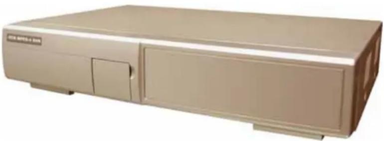
DMR - 504
natural_image
Exterior view of a beige industrial machine (no visible text or symbols)1) "HDD Cartridge Lock":
Lock / Unlock the cartridge of the HDD.
2) "USB":
Support firmware update and files backup.
3) "LED LIGHT":
HDD: HDD is reading or recording
HDD Full: HDD is full.
ALARM: Once the alarm is triggered
TIMER: When timer recording is turned on
PLAY: Under playing status
REC: Under recording status
4) "MENU":
Press "MENU" button to enter main menu.
5) "ENTER" / "SET":
Press "ENTER" button to confirm.
Press "SET" to change channel display position.
Press “▲▼◀▶” to select the channel which you like to change,
Press “ + ” or “ - ” select the channel which You would like to show.
Press "ENTER" button to confirm.
6) "SEARCH":
Press "SEARCH" button to enter the search mode.
7) "SLOW":
Under playback mode, press "SLOW" button to show slow playback.
7) "ZOOM":
Press "ZOOM" button to enlarge the picture of selected channel (2X digital zoom).
Press "Button to show the 4 channel display mode.
Press “ - ” button to change the setting in the menu.
9) “SEQ” / “ + ”:
Press "SEQ" button to activate the call monitor function and press "SEQ" button again to escape the call monitor mode.
Press “ + ” button to change the setting in the menu.
10) "POWER":
Press this button to turn on / turn off the DVR.
(Under recording mode, please stop record before turn off the DVR).
11) “CH1” “CH2” “CH3” “CH4”:
Press "1" "2" "3" "4" buttons to select the channel.
12) "REC":
Press "REC" button to activate the manual recording.
13) "PLAY":
Press "PLAY" button to playback the recorded files.
14) " UP / PAUSE, DOWN / STOP, LEFT / FAST REWIND, RIGHT / FAST FORWARD":
Press “▲▼◀▶” to move the cursor up / down / left / right.
Under playback mode, press "button to pause playback.
Under playback mode, press "button to stop playback.
Under playback mode, press "button to fast rewind.
Under playback mode, press "button to fast forward.
Press these two buttons to select live or playback sounds of the 4 audio channels.
Press these two buttons at the same time to enter / exit the PTZ control mode.
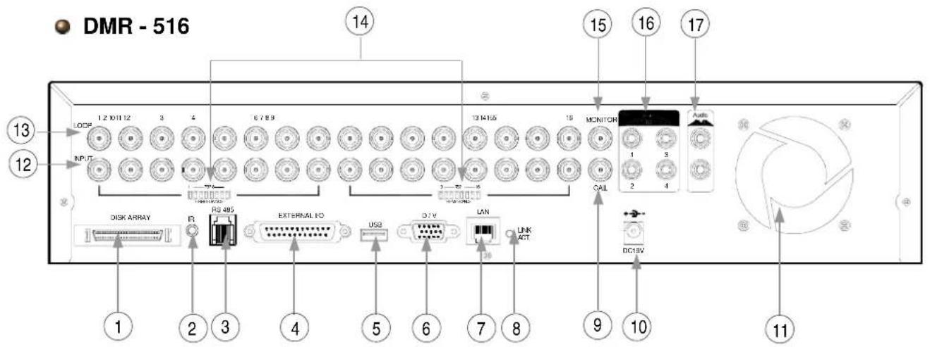
1.5 REAR PANEL
text_image
DMR - 516 14 15 16 17 12 13 12 1.2 10/11 12 3 4 6 7 8 9 13 M165 18 MONITOR 1 2 3 4 RS 485 EXTERNAL FO USB D.T.V LAN Link ACT SAL DC18V DISK ARRAY R 1 2 3 4 5 6 7 8 9 10 11DMR - 508
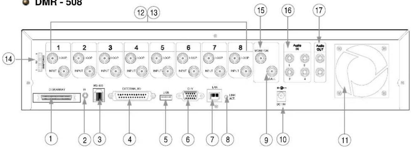
text_image
DMR - 508 12 13 14 1 2 3 4 5 6 7 8 MONITOR Audio IN Audio OUT DISKARRAY R RS 488 EXTERNAL IN USB D-V LAN LINK ACT. CALL DC 19V 1 2 3 4 5 6 7 8 9 10 11DMR - 504
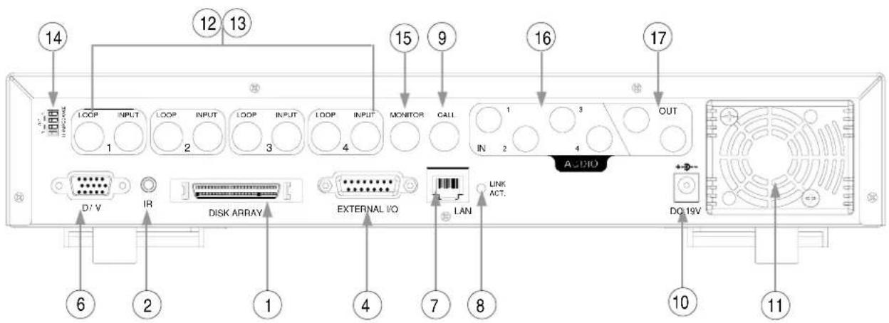
text_image
14 12 13 15 9 16 17 LOOP INPUT LOOP INPUT LOOP INPUT LOOP INPUT MONITOR CALL OUT 1 3 IN 2 4 D/V IR DISK ARRAY EXTERNAL I/O LAN LINK ACT. DQ 19V 6 2 1 4 7 8 10 111) DISK ARRAY PORT: Connect to disk array for extend HDD capacity.
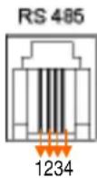
2: RS485B
3: RS485A
2) IR: Connect to IR receiver.
3) RS485: 1234 Connect to external device (such as PTZ camera) with RS485-A and RS485-B.
4) EXTERNAL I/O PORT: Connect to external device. Control external device or get controlled remotely by external device (alarm input, external alarm, PTZ camera).
5) USB PORT: Support firmware update and files backup.
6) D/V PORT (Digital Video Port): Connect to VGA connector card.
7) LAN: Connect to Internet by LAN cable.
8) LINK / ACT LED light: When the Internet is activated, the LED light will be on.
9) CALL MONITOR: Connect to CALL monitor. Show the channel switch display. When the alarm is triggered, the call monitor will show the image of the triggered channel for a period of time.
10) POWER: Connect to provided adapter.
12) VIDEO INPUT (CHANNEL 1 - 16 / CHANNEL 1 - 8 / CHANNEL 1 - 4) : Connect to video source, such as camera.
13) LOOP (CHANNEL 1 - 16 / CHANNEL 1 - 8 / CHANNEL 1 - 4): Video output.
14) 75Ω / HI: When using Loop function, please switch to HI. When you don't use Loop function, please switch to 75Ω.
15) MONITOR: Connect to Main monitor.
16) AUDIO IN (1-4): Connect to audio source, such as camera which equipped with audio function. When users start the recording function, the audio input will be recorded.
17) AUDIO OUT : Connect to monitor or speaker. With 2 mono audio outputs from the same source.
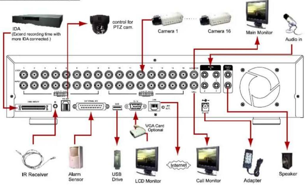
2.1 GETTING STARTED
Connecting all the devices to construct a surveillance.
1) Install HDD:
The HDD must be installed before the DVR is turned on.
2) Connect cameras.
3) Connect monitors.
4) Connect the external devices.
5) Connect the AC power cord to power adapter and plug into an electrical outlet.
NOTE:
The standby LED would be on as red.
Press the "POWER" button. The power LED will be on as red.
It takes approximately 10 to 15 seconds to boot the system.
NOTE:
Please refer to Appendix #1 for HDD installation instructions.
NOTE:
Please refer to "Section 1.5 Rear Panel" for connection.
Please refer to Appendix#2 for pin configurations of the external I/O port.
Take 16CH as an example
flowchart
graph TD
    A["IDA (Extend recording time with more IDA connected.)"] --> B["control for PTZ cam."]
    B --> C["Camera 1"]
    B --> D["Camera 16"]
    B --> E["Main Monitor"]
    B --> F["Audio in"]
    B --> G["VGA Card Optional"]
    G --> H["Internet"]
    G --> I["Call Monitor"]
    G --> J["Adapter"]
    G --> K["Speaker"]
    A --> L["IR Receiver"]
    A --> M["Alarm Sensor"]
    A --> N["USB Drive"]
    A --> O["LCD Monitor"]
    A --> P["Microcontroller"]
    A --> Q["Microcontroller"]
    A --> R["Microcontroller"]
text_image
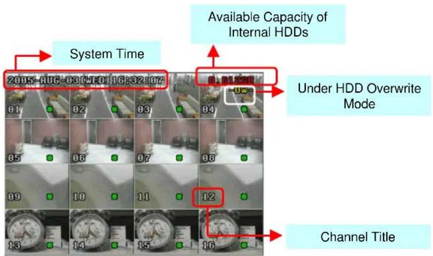
Available Capacity of Internal HDDs System Time 2005-06-03 04:10 16:32:07 81 82 83 84 85 86 87 88 89 10 11 12 13 14 15 16 Under HDD Overwrite Mode Channel Title3.1 RECORDING
The DVR offers three recording modes, manual record, event recording, and timer record. If power is off accidentally, recorded video files will still be stored in the HDDs. DVR will return to original recording status after power is on again.
1) MANUAL RECORDING (continuous recording): Recording is initiated by manually pressing the "REC" button. Indicated by the sign "●"
2) EVENT RECORDING (triggered by motion and external alarm): When this functions is activated, the recording is triggered by motion or external alarm. Indicated by the sign " and " .
3) TIMER RECORDING (scheduled time): Recording is scheduled by Timer. Indicated by the sign "TIMER RECORD".
NOTE :
When the HDDs are full under O/W recording mode, previous recorded files may be overwritten without further warning notices.
Take 16CH as an example
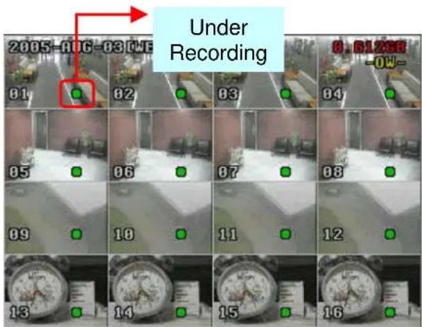
text_image
Under Recording 01-AUG-03 CWE 02 03 04 05 06 07 08 09 10 11 12 13 14 15 163.2 PLAYBACK
DMR - 516 / 508
16CH (D) / 8CH (D) / 4CH (D)
Press “PLAY” button, the DVR will display the last recording video.
1) FAST FORWARD (F.F.) & FAST REWIND (REW):
You can increase speed for fast forward and rewind on the DVR.
In the playback mode,
* Press "▶▶" once to get 4X speed forward and press twice to get 8X speed,... and the maximum speed can reach 32X.
* Press "◀◀" once to get 4X speed rewind and press twice to get 8X speed, ... and the maximum speed can reach 32X.
* The type of recording image size (Frame or CIF) will also shown on the screen.
2) PAUSE / IMAGE JOG:
Press "■ button to pause the current image displayed on the screen.
In the Pause mode,
* Press ▶ once to get forward by frame change.
* Press ◀ once to get rewind by frame change.
3) STOP:
Press “■” button under all circumstance, it will return DVR to live monitoring mode.
4) CHANNEL SHIFT:
* Display mode: Press MODE "button to select display mode.
* Full Screen Switch:
Press “+” or “-” button to show the full screen channels.
* Channel display switch: Press "SHIFT" button. SET
Press “▲” “▼” “◀” “▶” to select the channel which You would like to change.
Press “+” or “-” select the channel which You would like show.
Press "ENTER" button to confirm.
5) SLOW PLAYBACK:
Press “SHIFT” + “SLOW” button to get 1/4X speed playback and press twice to get 1/8X speed.
6) AUDIO:
Press “SHIFT” select AUDIO playback sounds of the 4 audio channels.
* AUDIO 1 (L) ; AUDIO 1 (P)
* AUDIO 2 (L) ; AUDIO 2 (P)
* AUDIO 3 (L) ; AUDIO 3 (P)
* AUDIO 4 (L) ; AUDIO 4 (P)
Note: For the playback of the DVD or CD backup file, please refer to "Section 4.13 ADVANCE MENU_BACKUP" for detailed instruction
DMR - 504
Press "PLAY" button, the DVR will display the last recording video.
1) FAST FORWARD (F.F.) & FAST REWIND (REW):
You can increase speed for fast forward and rewind on the DVR.
In the playback mode,
* Press “▶” once to get 4X speed forward and press twice to get 8X speed, ... and the maximum speed can reach 32X.
* Press “◀” once to get 4X speed rewind and press twice to get 8X speed, ... and the maximum speed can reach 32X.
* The type of recording image size (Frame or CIF) will also shown on the screen.
2) PAUSE / IMAGE JOG:
Press “☐” button to pause the current image displayed on the screen.
In the Pause mode,
* Press▶▶ once to get forward by frame change.
* Press once to get rewind by frame change.
3) STOP:
Press “■” button under all circumstance, it will return DVR to live monitoring mode.
4) CHANNEL SHIFT:
* Display mode:
Press MODE "button to 4 channels display.
* Full Screen Switch:
Press “ + ” or “ - ” button to show the full screen channels.
* Channel display switch:
Press "SET" to change channel display position.
Press “▲▼◀▶” to select the channel which you like to change,
Press “ + ” or “ - ” select the channel which You would like show.
Press "ENTER" button to confirm.
5) SLOW PLAYBACK:
Press "SLOW" button to get 1/4X speed playback and press twice to get 1/8X.
6) AUDIO:
Press “” to select live or playback sounds of the 4 audio channels.

* AUDIO 1 (L) ; AUDIO 1 (P)
* AUDIO 2 (L) ; AUDIO 2 (P)
* AUDIO 3 (L) ; AUDIO 3 (P)
* AUDIO 4 (L) ; AUDIO 4 (P)
DETAILED MENU CONFIGURATION
4.1 MENU TREE
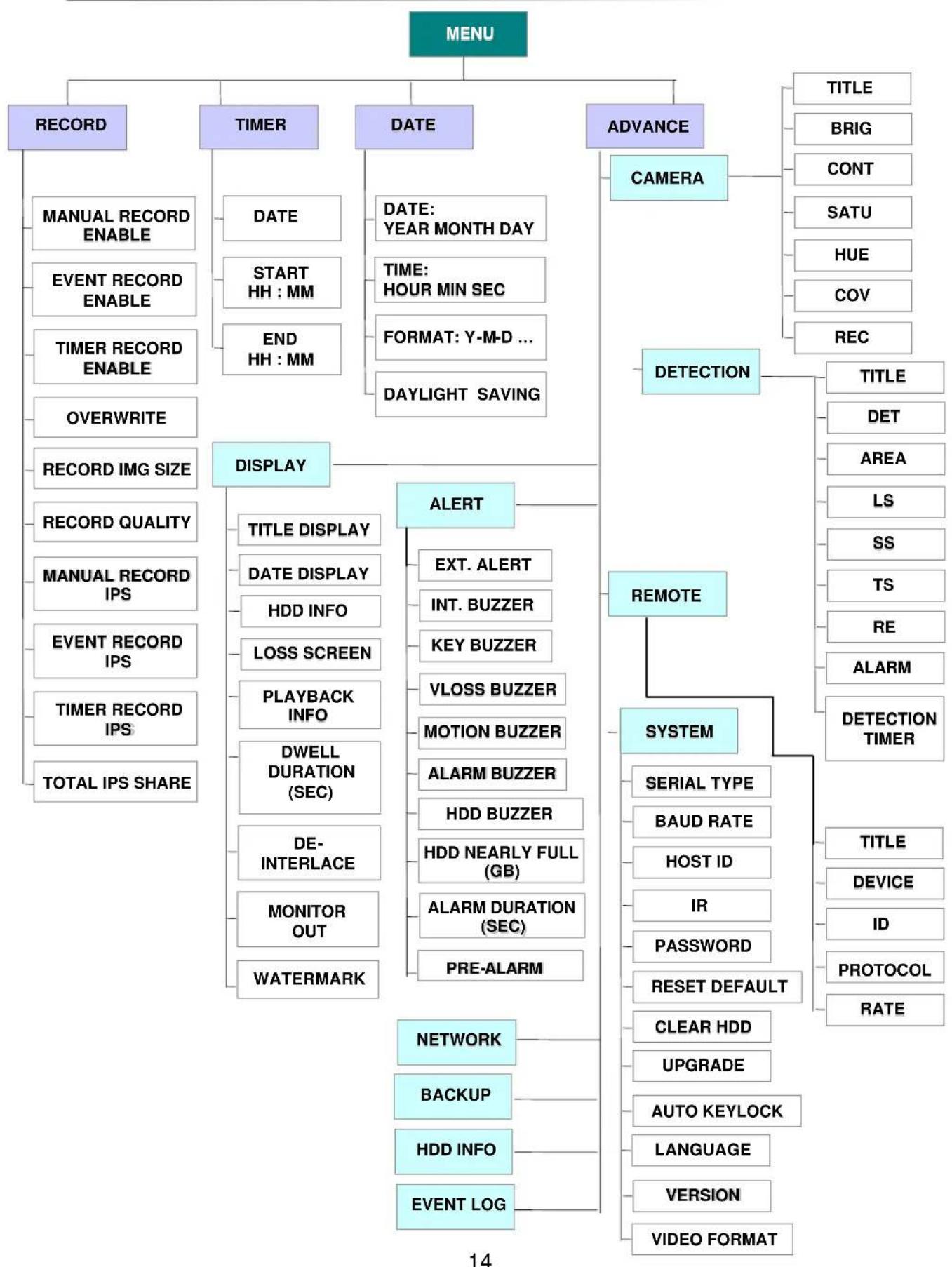
flowchart
graph TD
    A["MENU"] --> B["RECORD"]
    A --> C["TIMER"]
    A --> D["DATE"]
    A --> E["ADVANCE"]
    B --> F["MANUAL RECORD ENABLE"]
    B --> G["EVENT RECORD ENABLE"]
    B --> H["TIMER RECORD ENABLE"]
    B --> I["OVERWRITE"]
    B --> J["RECORD IMG SIZE"]
    B --> K["RECORD QUALITY"]
    B --> L["MANUAL RECORD IPS"]
    B --> M["EVENT RECORD IPS"]
    B --> N["TIMER RECORD IPS"]
    B --> O["TOTAL IPS SHARE"]
    C --> P["DISPLAY"]
    C --> Q["ALERT"]
    C --> R["REMOTE"]
    C --> S["SYSTEM"]
    S --> T["SERIAL TYPE"]
    S --> U["BAUD RATE"]
    S --> V["HOST ID"]
    S --> W["IR"]
    S --> X["PASSWORD"]
    S --> Y["RESET DEFAULT"]
    S --> Z["CLEAR HDD"]
    S --> AA["UPGRADE"]
    S --> AB["AUTO KEYLOCK"]
    S --> AC["LANGUAGE"]
    S --> AD["VERSION"]
    S --> AE["VIDEO FORMAT"]
    P --> F
    P --> G
    P --> H
    P --> I
    P --> J
    P --> K
    P --> L
    P --> M
    P --> N
    P --> O
    Q --> R
    Q --> S
    Q --> S
    R --> T
    R --> U
    R --> V
    R --> W
    R --> X
    R --> Y
    R --> Z
    R --> AA
    R --> AB
    R --> AC
    R --> AD
    R --> AE
4.2 MAIN MENU OPTIONS \_\_\_\_RECORD
Press "MENU" button to enter the main menu list. The default admin password is 0000. Enter the default password and press "ENTER". (Users could alter the password later, please refer to "Section 4.11 ADVANCE MENU SYSTEM")
Move the cursor to the "RECORD", and press "ENTER", then the screen will show the following options.
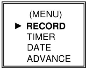
text_image
(MENU) ▶ RECORD TIMER DATE ADVANCEUse the following buttons for menu setting:
“▲▼◀▶” to move the cursor.
“+ , - ” to choose the numbers / selections.
"ENTER " to go to the submenu / to confirm the selection
"MENU " to go to the menu OSD / to confirm the change / to exit the menu OSD
Start / Stop the manual recording function.
2) EVENT RECORD ENABLE:
Start / Stop the event recording function. When this functions is activated, the recording will triggered by motion or external alarm
Start / Stop the timer recording function.
4) OVERWRITE:
Select to overwrite previous recording video in HDD. When the HDD is full under O/W recording mode, previous recorded files will be overwritten without further warning notices.
5) RECORD IMG SIZE:
There are two recording options: FRAME & CIF. When change record image size, user need to stop recording first.
6) RECORD QUALITY:
There are four quality settings: BEST, HIGH, NORMAL & BASIC
In the following (7) \~ (9) sections is for 16 channels.
For 8 channels, divided the IPS by 2. For 4 channels, divided the IPS by 4.
Recording is activated by pressing the "REC" button. Select the images per second of MANUAL RECORD, The options are as the followings:
NTSC: FRAME: 120, 60, 30, 15 PAL: FRAME: 100, 50, 25, 12
CIF: 480, 240, 120, 60 CIF: 400, 200, 100, 50
8) EVENT RECORD IPS:
Recording is activated by event (alarm and motion trigger). Select the images per second for event record, The options are as the followings:
NTSC: FRAME: 120, 60, 30, 15 PAL: FRAME: 100, 50, 25, 12
CIF: 480, 240, 120, 60 CIF: 400, 200, 100, 50
Recording is activated by timer schedule. Select the images per second of TIMER RECORD, The options are as the followings:
NTSC: FRAME: 120, 60, 30, 15 PAL: FRAME: 100, 50, 25, 12
CIF: 480, 240, 120, 60 CIF: 400, 200, 100, 50
10) TOTAL IPS SHARE:
There are two IPS settings: (Take 16ch as example)
FIX: IPS per channel = RECORD IPS ÷ 16 channels
GROUP: Every 4 channels will form a group.
IPS per channel = RECORD IPS ÷ 4 ÷ number of channels under recording within the group.
Ex.: If you set the record IPS as 480 IPS, then
Channel 01 will get 30 IPS (120 / 4 / 1 = 30)
Channel 05 and 06 each will get 15 IPS (120 / 4 / 2 = 15)
“●” means under recording
| 01 | Group 1:CH 01 ~ 04 | |||
| 05 | 06 | Group 2:CH 05 ~ 08 | ||
| Group 3:CH 09 ~ 12 | ||||
| Group 4:CH 13 ~ 16 |
NOTE: When users choose the image size as "CIF", the total IPS share will be fixed. That is IPS per channel will equal to record IPS divided by 16 channels.
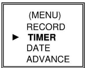
4.3 MAIN MENU OPTIONS\_TIMER
text_image
(MENU) RECORD ► TIMER DATE ADVANCEMove the cursor to the "TIMER", and press "ENTER", then the screen will show the following options.
A scheduled record date (SUN/MON/TUE/ WED/ THU/ FRI/ SAT/ MON-FRI / SAT-SUN / DAILY/OFF) could be set to activate the timer recording.
NOTE 1 : Specific date could be changed by “ + ” or “ - ” button.
NOTE 2 : If you plan to set the timer recording across the midnight, there are two ways for setting the timer recording schedule, please following the instructions below.
Example 1: If you only want to set recording timer schedule from every Sunday 23:30 to Monday 23:30, then you could set recording timer schedule as Sunday from 23:30 to 23:30.
Example 2 : If you plan to set the timer recording from Sunday 08:00 to Monday 15:00, then you could set the recording timer schedule as Sunday from 08 : 00 to 00 : 00, and Monday 00 : 00 to 15 : 00.
2) START:
Select the start time for the recording.
3) END:
Select the finishing time for the recording.
4.4 MAIN MENU OPTIONS\_DATE
(MENU)
RECORD
TIMER
▶ DATE
ADVANCE
Move the cursor to the "DATE", and press "ENTER", then the screen will show the following options.
| DATE |
| DATE 2005-NOV-08 13:55:22FORMAT Y-M-DDAYLIGHT SAVING ON |
1) DATE:
Set the correct time of the DVR (YEAR / MONTH / DAY / HOUR / MIN / SEC)
2) FORMAT:
There are three date formats: Y-M-D, M-D-Y, D-M-Y.
3) DAYLIGHT SAVING:
Specify whether to use daylight saving time and time period. ( START / END) Daylight saving time can be adjusted manually.
Enter the daylight saving menu mode to set start time, end time and adjust hour of the daylight saving.
| DAYLIGHT SAVING |
| START 4TH-SUN-MAR 01:00:00END 4TH-SUN-OCT 01:00:00ADJUST 01:00 |
NOTE: The illustrated setting means: During the daylight saving time period (start from the 4 ^th Sunday of March, end on the 4 ^th Sunday of October), the DVR system time will plus one hour.
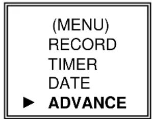
4.5 MAIN MENU OPTIONS ADVANCE
text_image
(MENU) RECORD TIMER DATE ► ADVANCE| ADVANCE |
| CAMERA |
| DETECTION |
| DISPLAY |
| ALERT |
| REMOTE |
| SYSTEM |
| NETWORK |
| BACKUP |
| HDD INFO |
| EVENT LOG |
Move the cursor to the "ADVANCE", and press "ENTER", then the screen will show the following options.
4.6 ADVANCE MENU \_\_\_\_ CAMERA
Move the cursor to the "CAMERA", and press "ENTER", then the screen will show the following options.
| Take 16CH as an example | CAMERA |
| TITLE BRIG CONT SATU HUE COV REC | |
| 01 110 128 128 128 NO YES | |
| 02 110 128 128 128 NO YES | |
| 03 110 128 128 128 NO YES | |
| 04 110 128 128 128 NO YES | |
| 05 110 128 128 128 NO YES | |
| 06 110 128 128 128 NO YES | |
| 07 110 128 128 128 NO YES | |
| 08 110 128 128 128 NO YES | |
| PREV NEXT | |
1) TITLE:
Move the cursor to the title which you want to change, and press "ENTER" to access the setting screen. Assign each channel a title (up to six characters (letters or symbols...)), the default title is the channel number.
2) BRIG / CONT / SATU / HUE:
Adjust the Brightness/Contrast/Saturation/Hue of each channel.
The level is from 0 to 255. The default value of BRIG is 110, others are 128.
3) COV (COVERT):
Select "YES" to mask the selected channel which is under recording.
When this function is activated, the "COV" words will shown on the screen.
4) REC (RECORD):
Select "YES" to enable the record function; Select "NO" to disable the record.
5) PREV / NEXT:
Select "PRE" to go to the previous page; Select "NEXT" to go the next page.
4.7 ADVANCE MENU \_\_\_\_DETECTION
Move the cursor to the "DETECTION", and press "ENTER", then the screen will show the following options.
| DETECTION |
| DETECTION SETUP |
| DETECTION TIMER |
1) DETECTION SETUP:
| Take 16CH as an example | DETECTION | ||||||
| TITLE DET AREA LS SS TS RE ALARM | |||||||
| 01 ON SETUP 07 03 02 10 OFF | |||||||
| 02 ON SETUP 07 03 02 10 LOW | |||||||
| 03 ON SETUP 07 03 02 10 HIGH | |||||||
| 04 ON SETUP 07 03 02 10 OFF | |||||||
| 05 ON SETUP 07 03 02 10 OFF | |||||||
| 06 ON SETUP 07 03 02 10 OFF | |||||||
| 07 ON SETUP 07 03 02 10 OFF | |||||||
| 08 | ON | SETUP | 07 | 03 | 02 | 10 | OFF |
| PREV NEXT | |||||||
a) TITLE:
Show the title of each channel of the camera.
b) DET:
Select "ON" to activate the motion detect function of each channel. Select "OFF" to inactivate the motion detect function of each channel.
c) AREA:
Press the "ENTER" button to set detection area.
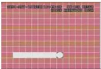
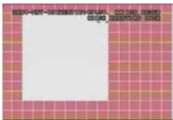
Pink blocks represent the area that is not being detected. While the transparent blocks is the area that is under detection.

natural_image
Grid pattern with pink and orange squares, no text or symbols visiblePress "ENTER" to confirm the start area
natural_image
Grid background with pink and orange squares, featuring a white horizontal bar and a small circle (no text or symbols)Press ◀ or ▶ to choose the width of the area
text_image
Cropped image showing a white rectangular area on a pink grid background with partial text above it.Press ◀ or ▶ to choose the height of the area, and press "ENTER" again to confirm.
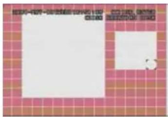
text_image
Scanned document page with red grid background and two blank white boxes, likely a form or template.Multi-detected area
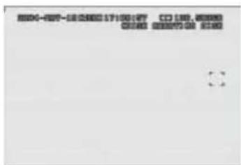
text_image
8004-807-5826031710017 CD 130,0000 00:00 00:00:00 01:00Press “-” to turn all area under detection
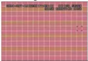
text_image
Scanned document with pink grid background and Chinese text, likely a form or report with redacted sections.Press “+” to turn all area not to be detected
▲▼◀▶: navigates between targets.
d) LS :
The sensitivity of comparing two different images. The smaller the value is, the higher sensitivity for motion detection.
The highest sensitivity setting is 00, the lowest sensitivity setting is 15. The default value is 07.
e) SS :
The sensitivity towards the size of the triggered object on the screen.(the number of motion detection grids). The smaller the value is, the higher sensitivity for motion detection.
The highest sensitivity setting is 00, and the lowest sensitivity setting is 15. The default setting is 03.
Note: The default setting of Spatial Sensitivity is 03, which means when 3 grids are detected for motion at one time, the system will get triggered. So the value of Spatial Sensitivity must be less than the number of grids which you set up to motion detection area.
f) TS :
The sensitivity towards how long the object gets triggered. The smaller the value is, the higher sensitivity for motion detection.
The highest sensitivity setting is 00, and the lowest sensitivity setting is 15. The default setting is 02.
g) RE :
The value of RE is a reference for detection. The default value is 10, which means DVR will compare 10 continuous images at one time according to the sensitivity of LS, SS, TS simultaneously. Therefore the bigger the value is, the higher sensitivity for motion detection.
h) ALARM :
Select LOW / HIGH for the alarm polarity. The default alarm value is OFF.
i) PRE / NEXT:
Select "PRE" to go to the previous page; Select "NEXT" to go the next page. Targets set in the AREA.
2) DETECTION TIMER:
Set the date, start time, end time of the detection function.
| DETECTION TIMER |
| DATE START ENDOFF 00 : 00 - 00 : 00DAILY 08 : 00 - 18 : 00SUN 06 : 00 - 23 : 00MON-FRI 00 : 00 - 00 : 00OFF 00 : 00 - 00 : 00OFF 00 : 00 - 00 : 00OFF 00 : 00 - 00 : 00 |
4.8 ADVANCE MENU \_\_\_\_DISPLAY
Move the cursor to the "DISPLAY", and press "ENTER", then the screen will show the following options.
| DISPLAY |
| TITLE DISPLAY ON |
| DATE DISPLAY ON |
| HDD INFO ON |
| LOSS SCREEN BLUE |
| PLAYBACK INFO NORMAL |
| DWELL DURATION (SEC) 2 |
| DE-INTERLACE ON |
| MONITOR OUT MAIN |
| WATERMARK ON |
1) TITLE DISPLAY: Turn the channel title display on / off.
2) DATE DISPLAY: Turn the date display on / off.
3) HDD INFO" Turn the display information of internal HDD on / off.
4) LOSS SCREEN" Set the color of video loss screen (Blue or Black)
5) PLAYBACK INFO: Set the position where playback information will be indicated (center or normal (on the button of left-hand side of the screen)).
6) DWELL DURATION (SEC): Set the duration time of each channel for CALL MONITOR (2, 4, 8, 16 sec.)
7) DE-INTERLACE: Set the "DE-INTERLACE" function on / off.
8) MONITOR OUT: Select video output device (Main monitor / VGA output (optional device))
9) WATERMARK: In the playback mode of the software AP, users could proof the authenticity of the BACKUP VIDEO. If the BACKUP VIDEO had been altered, the video image will turn to light red and the playback will be paused. Please refer to P. 36 for detailed instruction.
4.9 ADVANCE MENU \_ ALERT
Move the cursor to the "ALERT", and press "ENTER", then the screen will show the following options.
| ALERT |
| EXT. ALERT ON |
| INT. BUZZER ON |
| KEY BUZZER ON |
| VLOSS BUZZER ON |
| MOTION BUZZER ON |
| ALARM BUZZER ON |
| HDD BUZZER ON |
| HDD NEARLY FULL (GB) 05 |
| ALARM DURATION (SEC) 05 |
| PRE-ALARM OFF |
1) EXT. ALERT: Set the sound on / off when external alarm is triggered.
2) INT. BUZZER: Set the sound of KEY / VLOSS / MOTION / ALARM / HDD FULL on or off.
3) KEY BUZZER: Set the sound on / off when pressing the button.
4) VLOSS BUZZER: Set the sound on / off when video loss happened.
5) MOTION BUZZER: Set the sound on / off when motion alarm triggered.
6) ALARM BUZZER : Set the sound on / off when internal alarm triggered.
7) HDD BUZZER : Set the sound on / off when the HDD is full.
8) HDD NEARLYFULL (GB): If HDD buzzer is on, you could choose to have a buzzer notification when the HDD available capacity is only xxx GB left..
9) ALARM DURATION (SEC): Press "ENTER" or "+" or "-" button to set the duration time of alarm recording (5, 10, 20, 40 sec.).
10) PRE-ALARM: Set the pre-alarm function on (8MB) / off. When pre-alarm and event record functions are activated, the DVR will record 8MB file before alarm / motion triggered.
4.10 ADVANCE MENU \_\_\_\_REMOTE
Move the cursor to "REMOTE", and press "ENTER", then the screen will show the following options.
| Take 16CH as an example | REMOTE |
| TITLE DEVICE ID PROTOCOL RATE | |
| 01 PTZ 001 P - D 02400 | |
| 02 CAMERA 002 NORMAL 02400 | |
| 03 CAMERA 003 NORMAL 02400 | |
| 04 CAMERA 004 NORMAL 02400 | |
| 05 CAMERA 005 NORMAL 02400 | |
| 06 CAMERA 006 NORMAL 02400 | |
| 07 CAMERA 007 NORMAL 02400 | |
| 08 CAMERA 008 NORMAL 02400 | |
| PREV NEXT | |
1) TITLE:
Title of each camera.
2) DEVICE:
Select to control normal camera or PTZ camera for each channel.
3) ID:
Set the ID number (0 \~ 255) of PTZ camera.
Note: After connect to PTZ correctly, the default ID of PTZ will be shown on the screen.
Note: Please refer to below instruction "PTZ Connection and Control".
4) PROTOCOL:
Select NORMAL (our protocol) or PELCO-D protocol.
5) RATE:
Set the baud rate of each channel (2400, 4800, 9600, 19200, 57600).
\*\*\*PTZ Connection and Control: \*\*\*
1) Device: Our own brand PTZ / Pelco-D protocol PTZ
2) Connection: Detailed connection and instructions, please refer to PTZ manual.
Note:
As for "RS485A and RS485B Port" please refer to "Section 1.5 Rear Panel", or refer to "Appendix #2 PIN Configuration".
3) Control Mode: Refer to front panel / Refer to IR remote control manual.
4.11 ADVANCE MENU \_\_\_\_ SYSTEM
Move the cursor to the "SYSTEM", and press "ENTER", then the screen will show the following options.
| SYSTEM | |
| SERIAL TYPE RS - 485 | |
| BAUD RATE 02400 | |
| HOST ID 003 | |
| IR ON | |
| PASSWORD SETUP | |
| RESET DEFAULT RESET | |
| CLEAR HDD MASTER | |
| UPGRADE NO | |
| AUTO KEYLOCK NEVER | |
| LANGUAGE ENGLISH | |
| VERSION | 1042-09-H6-04-AA-08 |
| VIDEO FORMAT | NTSC |
1) SERIAL TYPE:
Press "ENTER" or "+" or "-" button to set the control serial type (RS-485, RS-232) of DVR.
2) BAUD RATE:
Press "ENTER" or "+" or "-" button to set the BAUD RATE of DVR (2400, 9600, 19200, 57600).
3) HOST ID:
Press "ENTER" or "+" or "-" button to set the ID of DVR (0 \~ 255).
4) IR:
Press "ENTER" or "+" or "-" button to set the IR function on / off.
5) PASSWORD:
Press “ENTER” to set the password for accessing DVR (admin password or guest password). Users who use guest password to access the DVR will only allow to view the live streaming video, sequence display, shift the channel display, and key lock.
6) RESET DEFAULT:
Press "ENTER", and select "YES" to confirm or "NO" to cancel.
7) CLEAR HDD:
Press "ENTER", and "YES" to confirm clear HDD or "NO" to cancel. In this function, you can press "+" or "-" to select the HDD MASTER HDD, SLAVE HDD or DISK ARRAY which you plan to clear.
8) UPGRADE:
Press "ENTER", and select "YES" to confirm upgrade or "NO" to cancel.
9) AUTO KEYLOCK :
Set the auto key lock function (Never / 10 sec / 30 sec / 60 sec).
10) LANGUAGE:
Press "ENTER", and select the language of the OSD.
11) VERSION:
The firmware version information will be shown on the screen.
12) VIDEO FORMAT:
The information of the DVR's video format will be shown on the screen.
4.12 ADVANCE MENU \_\_\_\_NETWORK
Move the cursor to the "NETWORK", and press "ENTER", then the screen will show the following options.
| NETWORK | |
| NETWORK TYPE STATIC | ____ |
| DNS 168. 95. 1. 1 | ____ ____ ____ |
| PORT 0 0 8 0 | ____ ____ ____ |
1) NETWORK TYPE (STATIC):
Select NETWORK TYPE, and press “+” or “-” button to set the network type as STATIC, and then press “ENTER” to go to the submenu of the network. In the submenu of network type, use “+” or “-” button to set all the information needed in the DVR. See the illustration below.
| STATIC | |
| IP 60 | ____.121.46.236 |
| GATEWAY 60. 121. 46. 226 | ____ ____ ____ |
| NETMASK 255. 255. 255. 254 | ____ ____ ____ ____ |
2) NETWORK TYPE (DHCP):
This DHCP function need to be supported by router or cable modem network with DHCP service. For detailed DHCP setting, please refer to P.37 and P.38 (Licensed Software AP).
3) NETWORK TYPE (PPPoE):
This PPPoE function need to have “username” and “password” from ISP supplier. For detailed PPPoE setting, please refer to P.37 and P.38 (Licensed Software AP).
NOTE:
DHCP and PPPoE network types need to apply DDNS service to get "Hostname" to correspond to dynamic IP address. For detailed DDNS setting, please refer to P.38.
4.13 ADVANCE MENU BACKUP
DMR - 516 / 508 / 504
Move the cursor to the "BACKUP", and press "ENTER", then the screen will show the following options.
| BACKUP |
| USB BACKUP |
Select "USB BACKUP" and then press "Enter".
| USB BACKUP |
| START TIME 2005-12-27 11 : 25 : 46END TIME 2005-12-27 11 : 50 : 58AVAILABLE SIZE 0512 MBCHANNEL 01HDD NUM MASTERBACKUP TO USB START |
1) START TIME:
Select the start time of the backup.
2) END TIME: Select the end time of the backup.
3) AVAILABLE SIZE: The information of the USB available capacity.
4) CHANNEL: Choose the channel.
5) HDD NUM: Choose the HDD.
6) BACKUP TO USB: Press "ENTER" to start backup the chosen file to USB.
NOTE:
① The USB format must be "FAT 32".
② If the USB is not supported by the DVR, then the "USB ERROR" message will be shown on the screen.
③ It is suggest that clear all the files in the USB before you backup files in your USB.
④ The file type of the backup files could use the licensed software to view the playback. Or convert to AVI format and playback with other software (such as Media Player or RealPlayer).

flowchart
graph LR
    A["20051228_10\n5632_0T"] --> B{Do you want to convert this file?}
    B -->|Cancel| C["Play File"]
    B -->|Cancel| D["End"]
Move the cursor to the "BACKUP", and press "ENTER", then the screen will show the following options.
| BACKUP |
| USB BACKUPDISK BACKUP |
Select "DISK BACKUP" and then press "Enter".
| DISK BACKUP |
| START TIME 2005-11-30 15:30:00END TIME 2005-12-01 16:00:00AVAILABLE SIZE 4083 MBCHANNEL 01HDD NUM MASTERBACKUP TO DISK START |
1) Press “+” and “-” buttons to open the DVD / CD WRITER.
Put the DISK into DVD / CD WRITER, and press “+” and “-” buttons again to close.
(NOTE: Use DVD-R DISK only)
2) Go to "DISK BACKUP" menu and set the start time, end time, channel and HDD number.
3) After setting up the backup information, move the cursor to "START", and press "ENTER".
While the files are backup to DISK, users will see the backup completed percentage on the screen.
4) After backup files to DISK, "DISK BURN FINISH" will prompt on the screen.
Press “+” and “-” to take out the DISK from DVD / CD WRITER.
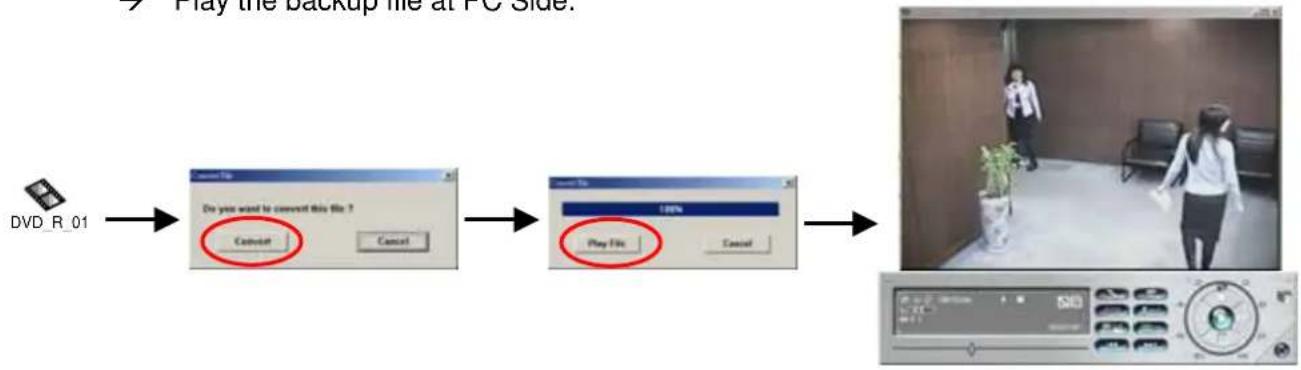
5) Put DISK into the DVD / CD -ROM of PC.
(O/S system: Windows XP, and Windows2000).
And then double click the file → Convert the file
→ Play the backup file at PC Side.
flowchart
graph LR
    A["DVD_R_01"] --> B["Do you want to convert this file?"]
    B --> C["Play File"]
    C --> D["Virtual photo with person walking in room"]
4.14 ADVANCE MENU \_\_\_\_HDD INFO
You can get all the capacity information of the connected HDD.
| HDD INFO |
| HDD NUM HDD SIZE HDD NUM HDD SIZEMASTER 400.517 SLAVE NO HDDEXT001 400.517 EXT 002 400.517EXT003 400.517 EXT 004 NO HDDEXT005 NO HDD EXT 006 NO HDDEXT007 NO HDD EXT 008 NO HDDEXT009 NO HDD EXT 010 NO HDDEXT011 NO HDD EXT 012 NO HDD |
4.15 ADVANCE MENU \_\_\_\_EVENT LOG
You can get all the information (event type, time, and channel) of the event list (including video loss list, net list, other lists (such as power on / off, key unlock, reset to default). Select the event list you want to see and press "ENTER".
| EVENT LOG | |
| VLOSS | LIST |
| NET | LIST |
| OTHERS | |
| CLEAN | ALL |
1) VLOSS LIST:
Show the information of video loss list.
2) NET LIST:
Show the information of net login list.
3) OTHERS:
Show the information of power on / off, unlock, reset to default list.
4) CLEAN ALL:
Clear all the event log lists.
5.1 SEARCH
DMR - 516 / 508
16CH (D) / 8CH (D) / 4CH (D)
Press "SHIFT" buttons on the front panel of the DVR to enter the search mode. Then the screen will show the following options.
4CH
Press "SEARCH" buttons on the front panel of the DVR to enter the search mode. Then the screen will show the following options.
| SEARCH |
| HDD MASTERFULL LISTRECORD LISTSYSTEM LISTALARM LISTMOTION LISTEVENT SEARCHTIME SEARCH |
1) HDD:
Select the the specific HDD.
2) FULL LIST:
List all recorded files
( R: RECORD / S: SYSTEM / A: ALARM / MS: MOTION / T: TIMER).
3) RECORD LIST:
List of manual recorded files.
4) SYSTEM LIST:
List of system recorded files.
Under continuous recording mode, the DVR system will save one recording file every one hour.
5) ALARM LIST:
List of alarm trigger recorded files.
6) MOTION LIST:
List of motion trigger recorded files.
7) EVENT SEARCH:
Search by specific time period (YEAR / MONTH / DAY / HOUR / MIN / CHANNEL).
Display all the motion triggered recording videos.
When you saw the playback of the motion triggered recording videos, it would play with fast speed.
8) TIME SEARCH:
Search by specific time period (YEAR / MONTH / DAY / HOUR / MIN).
NOTE:
Move the cursor to the specific recorded file and press "ENTER" to play the video, and press stop "■button to return the live display.
5.2 2X DIGITAL ZOOM
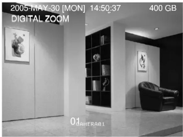
Press "ZOOM" button on the front panel of the DVR to enlarge the picture of selected channel (2X digital zoom). You will have 1/4 view size of the enlarged picture. Therefore use the "▲▼◀▶" to navigate.
text_image
2005-MAY-30 [MON] 14:50:37 400 GB DIGITAL ZOOM 01 CAMERA01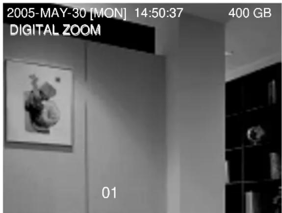
text_image
2005-MAY-30 [MON] 14:50:37 400 GB DIGITAL ZOOM 011) Press the "ZOOM" button again to exit the zoom picture.
2) Press “▲▼◀▶” button to move the zoom position.
3) Users could also press the "Digital Zoom" button on the IR remote control panel.
5.3 KEY LOCK
1) Key Lock On:
① Press "MENU" + "ENTER" buttons on the DVR front panel to key lock.
② Press "F2" button on the IR remote control to key lock.
③ Auto key lock: refer to "Section 4.11 ADVANCE MENU_SYSTEM".
2) Key Lock Off:
Press any key (except "SHIFT" and "POWER" buttons)
and then key in the password to exit Key Lock mode.
3) Password:
As to the password setting, please refer to "Section 4.11 ADVANCE MENU SYSTEM".
5.4 SWITCH THE N/P SYSTEM
1) Press "POWER" button on the DVR front panel to shutdown, and then press "POWER" + "▶" to switch to PAL system.
(Press till the monitor show the video image of the DVR.)
2) Press "POWER" button on the DVR front panel to shutdown, and then press "POWER" + "◀" to switch to NTSC system.
(Press till the monitor show the video image of the DVR.)
5.5 USB UPGRADE
Users can use USB to upgrade.
Please format the USB memory device as FAT 32 format first.
1) Get the upgrade files from your distributor.
2) Save the upgrade files in your USB device (Do not change the file name).
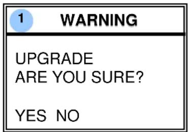
3) Go to the "MAIN MENU - SYSTEM - UPGRADE", and press "ENTER".
4) Select "YES", and press "ENTER" again to confirm upgrade.
text_image
1 WARNING UPGRADE ARE YOU SURE? YES NO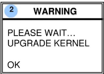
text_image
2 WARNING PLEASE WAIT... UPGRADE KERNEL OK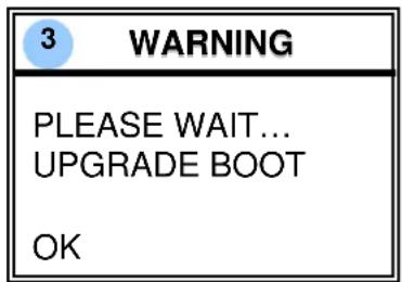
text_image
3 WARNING PLEASE WAIT... UPGRADE BOOT OK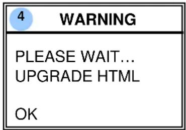
text_image
4 WARNING PLEASE WAIT... UPGRADE HTML OK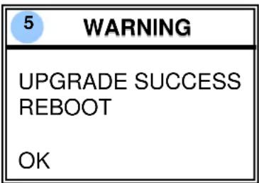
text_image
5 WARNING UPGRADE SUCCESS REBOOT OK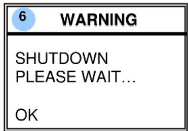
text_image
6 WARNING SHUTDOWN PLEASE WAIT... OKNOTE:
① The USB format must be "FAT 32".
② If the USB can't be detected by the DVR, the "USB ERROR" message will be shown on the screen.
5.6 LICENSED SOFTWARE AP
1) Install the Software:
① Place the attached CD into CD-ROM and it will start to install application programs into PC (Including AP and JAVA program).
② The PC will run the setup file automatically.
③ After setup, user will see “ ” icon on the desktop.
Video Server E
NOTE:
For the latest version of the software AP, please refer to your distributor, or refer to "Section 5.7 CONNECT TO AP VIA IE BROWSER".
2) Software Operation:
① Connect DVR to PC via RJ45 network line.
② LAN Setting :
The default DVR IP is “192.168.1.10”, and default “username” and “password” are both “admin”. Users should set PC’s IP address as “IP:192.168.1.XXX (1\~255, except 10)” (in order to make the PC and DVR under the same domain).
③ Double click to enter login page.
Key in IP (192.168.1.10), username (admin), password (admin), port (80) in the login page. After connect to the DVR with local LAN, users could modify the network settings in DVR or in system config of the licensed software AP.
④ Network Type \~ Static IP :
Set the network information in the DVR menu (Section 4.12) or in System Config of the licensed software AP (P.37).
Network Type \~ Dynamic IP (DHCP and PPPoE) :
Set the Network information in System Config of the licensed software AP. For detailed DHCP and PPPoE setting, please refer to P.37 and P.38.
⑤ After setup the network information, double click 📋 to enter login page. Key in “Username”, “Password”, “IP” (Static IP) or “Host name” (Dynamic IP), and “Port”. And then click the green button to connect.
⑥ LOGIN AP Icon Explanation.

Address Book: Press this button to add a new IP into the IP Address Book or choose any preset IP address to access the software AP.

Copy: Press this button to copy all the software installation files, so users could keep all the settings of video web server for next software installation on other PC.

Search: Search available DVR IP address in local area network and modify the network setting of the DVR.

Upgrade Firmware: Press this button, upgrade DVR firmware. The provided firmware files should be saved at PC first.

Player: Press this button to access and play the recorded files that are saved in your PC.
NOTE: The version of the licensed software will shown on the login page.
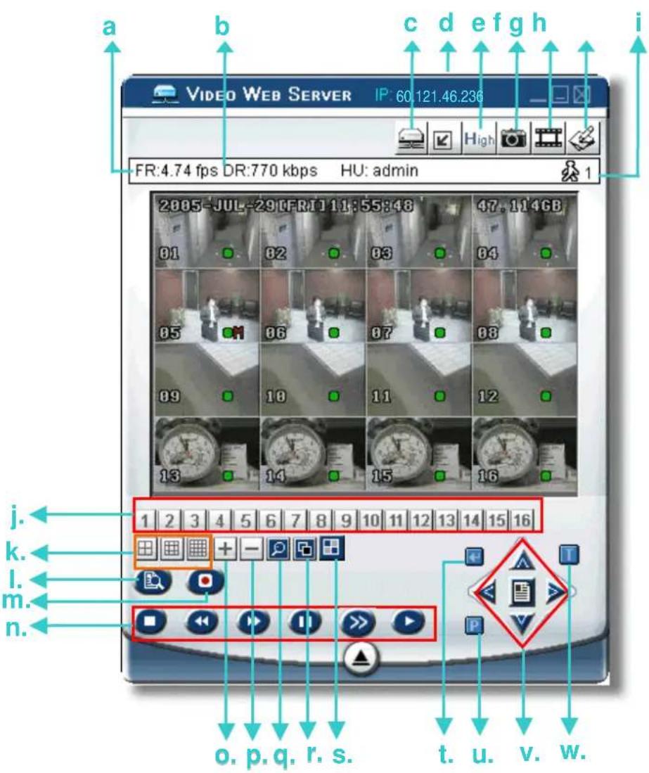
⑦ Introduction of Basic Operation : Video Web Server Control Panel.
Digital Device Control Panel \~ Take 16CH DVR as an example
text_image
a b c d e f g h i FR:4.74 fps DR:770 kbps HU: admin 2005-JUL-29 [FRI] 11:55:48 01 02 03 04 05 06 07 08 09 10 11 12 13 14 15 16 j. k. l. n. o. p. q. r. s. t. u. v. w.a. Image Transfer Rate Per Second
b. Data Transfer Rate
c. Connect / Disconnect
d. Resolution:
NTSC: 320 × 228 ; 640 × 456
PAL: 320 × 276 ; 640 × 552
e. Image Quality (High, Medium, Low)
f. Snapshot : press this button to have a snapshot of the image which will be saved in the designated destination.
g. Record : press this button to start recording, and press this button again to stop recording. The recorded files will be saved to the designed path on the PC. Each recording file can be up to 18,000 frames. When the recording file is full, the new recorded file will be saved as the second file.
If the HDD space is less than 200MB, the program will stop recording.
h. System Config: press this button to enter the setting page of the software AP.
i. Number of Online Users
j. CH 1 \~ 16
k. 4, 9, 16 Channel Display
I. Search
m. Record
n. Stop / Fast Rewind / Fast Forward / Pause / Slow Playback / Play
- +
p. -
q. Digital Zoom
r. Set : press this button to change channel display position.
Press “▲▼◀▶” to select the channel which You would like to change.
Press “ + ” or “ - ” select the channel which You would like to show.
Press "Enter" button to confirm.
s. Sequence: press this button to enter the call monitor function and press again to exit from call monitor mode.
t. Enter
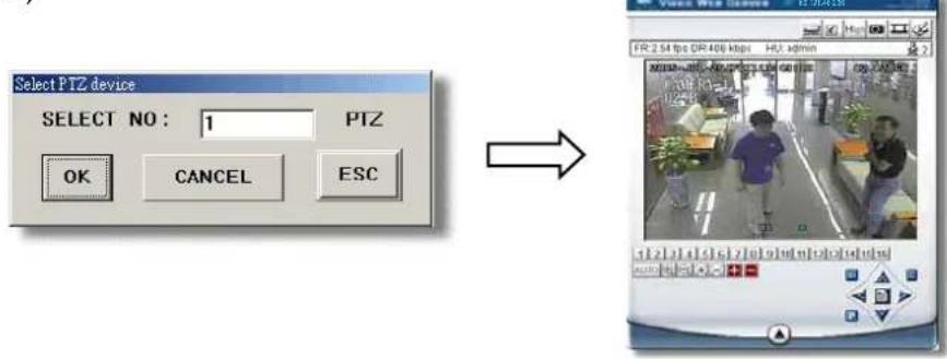
u. PTZ Control On / Off:
When the PTZ control turned on, users could select
the PTZ device, and press "OK" button to enter the PTZ control AP screen.
(Press "ESC" to exit from PTZ control AP screen and back to DVR control AP screen)
text_image
Select PTZ device SELECT NO : 1 PTZ OK CANCEL ESC → EPR: 2.54 fps GR 406 kbps HU admin EPR: 2.54 fps GR 406 kbps HU adminv. Menu / Up / Down / Left / Right
w. Turbo ON/ OFF:
To speed up menu selection or the control of the PTZ camera under software AP, users could activate "Turbo" function by clicking this button. Users are allowed to change the turbo steps from 1 to 10. .
Ex. If users activate the TURBO function, and set the value of the turbo step as 3, then when users press one of the button up/down/left/right, one mouse click will function as clicking 3 times.
text_image
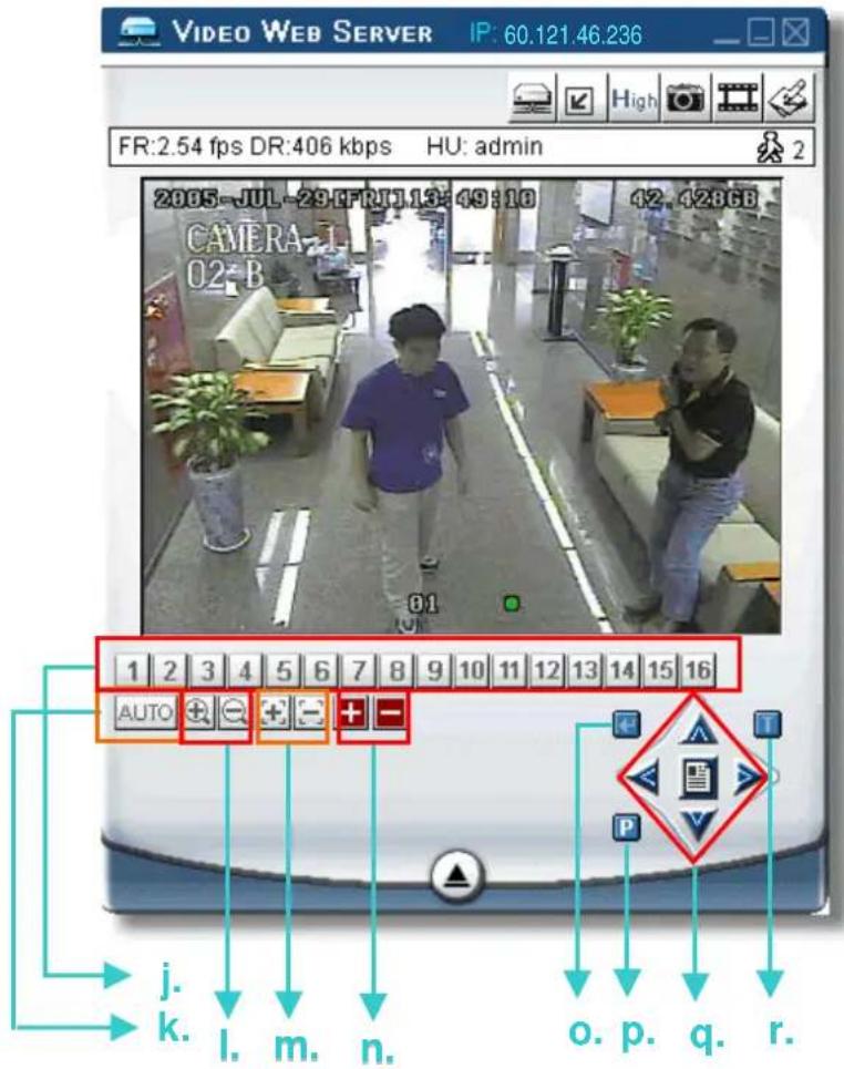
VIDEO WEB SERVER IP: 60.121.46.236 FR:2.54 fps DR:406 kbps HU: admin 2005-JUL-29-FRJ1.13:49:10 42.42853 CAMERA-1 02-B 1 2 3 4 5 6 7 8 9 10 11 12 13 14 15 16 AUTO AUTO AUTO AUTO AUTO AUTO AUTO AUTO AUTO AUTO AUTO AUTO AUTO AUTO AUTO AUTO AUTO AUTO AUTO AUTO AUTO AUTO AUTO AUTO AUTO AUTO AUTO AUTO AUTO AUTO AUTO AUTO AUTO AUTO AUTO AUTO AUTO AUTO AUTO AUTO AUTO AUTO AUTO AUTO AUTO AUTO AUTO AUTO AUTO AUTO AUTO AUTO AUTO AUTO AUTO AUTO AUTO AUTO AUTO AUTO AUTO AUTO AUTO AUTO AUTO AUTO AUTO AUTO AUTO AUTO AUTO AUTO AUTO AUTO AUTO AUTO AUTO AUTO AUTO AUTO AUTO AUTO AUTO AUTO AUTO AUTO AUTO AUTO AUTO AUTO AUTO AUTO AUTO AUTO AUTO AUTO AUTO AUTO AUTO AUTO AUTO j. k. l. m. n. o. p. q. r.j. Preset 1 \~ 16
k. AUTO
I. Zoom+Tele
m. Focus Near
n. MaxZoom In
o. Enter
p. PTZ Control On / Off:
When PTZ control mode is turned on, users could select the PTZ device, and press "OK" button to enter the PTZ control AP screen. (Press "ESC" to exit from PTZ control AP screen and back to DVR control AP screen)
q. Menu / Up / Down / Left / Right
r. Turbo:
To speed up menu selection or the control of the PTZ camera under software AP, users could activate "Turbo" function by clicking this button. Users are allowed to change the turbo steps from 1 to 10.
Ex. If users activate the TURBO function, and set the value of the turbo step as 3, then when users press one of the button up/down/left/right, one mouse click will function as clicking 3 times.
⑧ Playback Operation
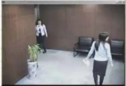
AP Playback Window :
natural_image
Interior view of a modern office hallway with two women walking, a potted plant, and a bench (no visible text or signage)AP Config. Setting Box :
text_image
C:\Documents and Settings\ PATH A TEXT PROGRESS Mute OK Record Style : User Record Size : 5007351 Bytes Resolution : 720 x 480 Date : 05/12/27 09:10:01One click to activate
text_image
De-interface De-blocking OSD AVI Convert Config. Setting Watermark Open Previous File Open Next File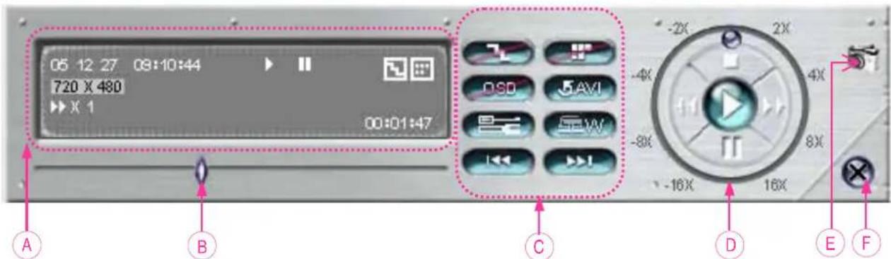
text_image
05 12 27 08:10:44 720 X 480 X 1 00:01:47 A B C D E FA. Playback Information :
Display information such as "Date", "Time", "Resolution", "Rewind / Forward Speed", "Status" and "Functions", etc..
B. Time Progress Bar :
Show the playback progress status.
C. Functions :
text_image
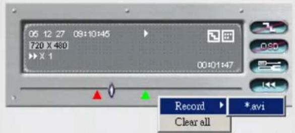
05 12 27 08:10:45 720 X 480 >> X 1 00:01:47 Record *.avi Clear allTo snap video, right-click of the mouse to make a starting point (red) and click one more time to make a ending point. Then right-click to convert to AVI format.
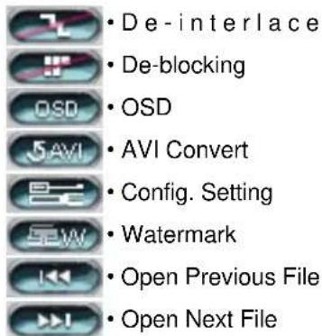
- De-interlace: Reduce the vibration of the paused picture.
- De-blocking: Reduce the video mosaic phenomenon.
- OSD: Display the OSD of the AP playback window.
- AVI convert: Convert the entire recorded file to AVI format.
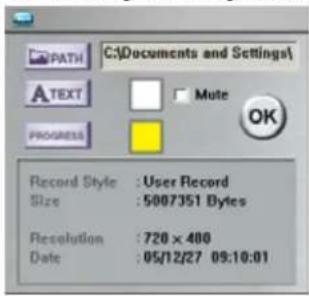
- Config. Setting: Enter AP config. setting box, and set the file destination, text color, and text color of progress status.
- Watermark: Proof the authenticity of the backup video.
- Open Previous File: Open previous backup video.
- Open Next File: Open next backup video.
D. Playback Control Buttons :
Play / Stop / Pause / Fast Rewind / Fast Forward
E. Snapshot :
Press this button to take a snapshot of the current image which will be saved in the designated destination.
F. Close the Player.
Note:
- When users pause the playback picture, press "button to go to the previous frame, or press "button to go to the next frame.
- In the playback mode of the software AP, users could press "button" to check the authenticity of the BACKUP VIDEO. If the BACKUP VIDEO had been altered, the video image will turn to light red and the playback will be paused.
3) Advanced Setting:

text_image
VIDEO WEB SERVER IP: 60.121.46.236☐ Press "System Config 🔍" button to enter the system setting page.
Network
The network configuration allows DVR to be available for Ethernet network or dial-up.
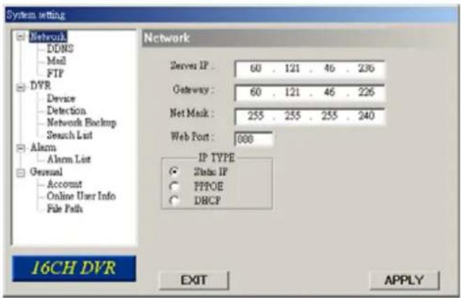
① Static IP:
Enter the "server IP", "gateway", "net mask" and "web port", then press "APPLY" to confirm.
② PPPoE:
Enter the "username" and "password" provided by your ISP (Internet Sever) supplier, then press "APPLY" to confirm.
③ DHCP:
This DHCP function need to be supported by router or cable modem network with DHCP service. Choose the DHCP IP type and press "APPLY" to confirm.
\*\*\*Note\*\*\*:
PPPoE and DHCP network connection type will require to apply DDNS service to get a "Hostname" to correspond to dynamic IP address.
Please refer to P.38 for details.
\*\*\*Note\*\*\*:
Some router brand may need to restart the DVR to get the IP address.
④ Web Port:
The DVR can be viewed over the network with software AP or a web browser. Typically the TCP port used by HTTP is 80. However in some cases it is better to change this port number for added flexibility or security. Valid number is 80 \~ 19999.
text_image
System setting Network DDNS Mail FTP DVR Device Detection Network Backup Search List Alarm Alarm List General Account Online User Info File Path Network Server IP : 60 . 121 . 46 . 236 Gateway : 60 . 121 . 46 . 226 Net Mask : 255 . 255 . 255 . 240 Web Port : 000 IP TYPE Static IP PPPOE DHCP 16CH DVR EXIT APPLY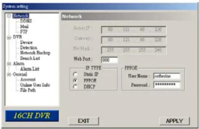
text_image
System setting Network DDNS Mail FTP DVR Device Detection Network Backup Search List Alarm Alarm List General Account Online User Info File Path Network Server IP: 60 121 46 236 Outflow: 60 121 46 236 Bit Mark: 255 255 255 240 Web Port: 898 IP TYPE Static IP PPPOE DHCP PPPOE User Name : catharine Password : ********* EXIT APPLY 16CH DVR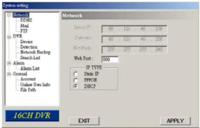
text_image
System setting Network DDNS Mail FTP DVR Device Detection Network Backup Search List Alarm Alarm List General Account Online User Info File Path 16CH DVR Network Server IP: 60 . 121 . 46 . 226 G Devr: 60 . 121 . 46 . 226 Net Mark: 255 . 255 . 255 . 240 Web Port: 000 IP TYPE Static IP PPPOR DHCP EXIT APPLYDDNS
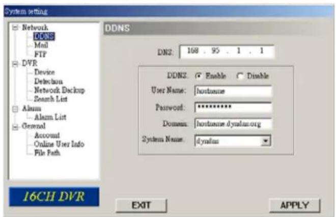
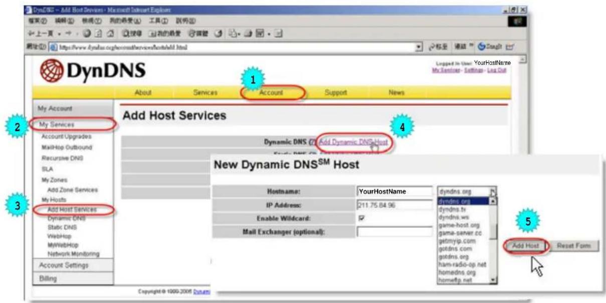
① DDNS is a service for transforming dynamic IP to corresponding to a specific "Hostname".
② DDNS Apply:
Go to a website which provide free DDNS services and apply a "Hostname". See the example below.
③ Enable the DDNS function:
Enter "DDNS username" into "username" column.
Enter the "DDNS password" into "password" column.
Enter the "Hostname" into "Domain" column.
Choose the "DDNS system name".
After setting, press "APPLY" to confirm.
text_image
System setting Network DDNS Mail FTP DVR Device Detection Network Backup Search List Alarm Alarm List General Account Online User Info File Path DDNS DNZ: 168 . 95 . 1 . 1 DDNZ: Enable Disable User Name: hostname Password: ********** Domain: hostname dynlus.org System Name: dynlus 16CH DVR EXIT APPLYDDNS APPLY EXAMPLE:
☐ Go to a website which provide free DDNS services.
For example, "http://www.dyndns.org".
☐ Create an account in DynDNS.
☐ After created your account, users will receive an confirmation e-mail within few minutes. To complete registration, please follow the instructions received.
Users must complete these steps within 48 hours to complete the registration. If the confirmation e-mail was not received within an hour, request "password reset" (http://www.dyndns.org/account/resetpass/).
☐ Use the DDNS username and password to login the DynDNS.
□ Create Hostname:
Login → “Account” → “My Service” → “Add Host Services” → “Add Dynamic DNS Host” → Enter and choose the hostname → Click on “Add Host” → DDNS Hostname created.
text_image
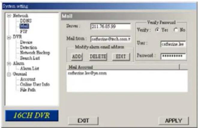
DynDNS About Services Account Support News 1 2 My Account My Services Account Upgrades MailHop Outbound Recursive DNS SLA My Zones Add Zone Services My Hosts Add Host Services Dynamic DNS Add Dynamic DNS Host New Dynamic DNS™ Host Hostname: YourHostName IP Address: 211.75.84.96 Enable Wildcard: Mail Exchanger (optional): dyndns.org dyndns.org dyndns.tx dyndns.ws game-host.org game-server.cc getmyip.com gotdns.com gotdns.org ham-radio-op.net homedns.org homeftp.net 5 Add Host Reset Form 3 Account Settings Billing Copyright © 1000-2005 DynDNS① When alarm or motion is triggered, a video copy file can be captured. DVR can send e-mail notification to the assigned recipients (up to 5 recipients).
\*\*\*Note\*\*\*:
To activate the e-mail notification function, please enable the function of e-mail notification in the "Alarm" setting first (page 43).
② Add the recipients' email accounts in the "Mail Account" column. The detailed information (SMTP server, username and password) refer to e-mail system supplier.
③ Please type in the entire email address in the "Mail from" column to ensure emails will not be blocked by SMTP.
④ In some cases, mail server require to verify password, please enter the "user name" and "password".
⑤ After setting, press "APPLY" to confirm.
text_image
System setting Network DDNS Mail FTP DVR Device Detection Network Backup Search List Alarm Alarm List General Account Online User Info File Path Mail Server : 211.76.05.99 Mail from : catherine@tech.com p Modify alarm email address ADD DELETE EDIT Verify Password Verify: Yes No User : catherine.lee Password : ********** Mail Account catherine.lee@ya.com 16CH DVR EXIT APPLYFTP
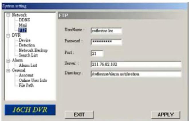
① When alarm or motion is triggered, a video copy file can be captured. And DVR can upload the captured images to the assigned FTP site.
② Enter the detailed FTP information.
\*\*\*Note\*\*\*:
To activate the FTP notification function, please enable the function of FTP notification in the "Alarm" setting first.
③ After setting, press "APPLY" to confirm.
text_image
System setting Network DDNE Mail FTP DVR Device Detection Network Backup Search List Alarm Alarm List General Account Online User Info File Path 16CH DVR FTP UserName : catherine.lee Password : ********** Port : 21 Server : 211.76.82.102 Directory : Altletune/alarm notification EXIT APPLYDVR – Camera Setting
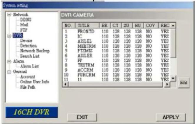
① Each camera channel can be adjusted independently.
② Select the desired camera channel. Press "Edit" to enter the setting box.
③ Title: Enter the camera channel name up to 6 characters.
④ Adjustment: Adjust the BR (brightness) / CT (contrast) / SU (saturation) / HU (hue) / REC (recording) of the camera.
⑤ After setting, press "OK" and then press "APPLY" to confirm.
Take 16CH as an example
text_image
System setting Network DDNS Mail FTP DVR Device Detection Network Backup Search List Alarm Alarm List General Account Online User Info File Path 16CH DVR DVTR CAMERA NO. TITLE BR CT SU HU COV REC 1 FRONTD 110 128 128 128 NO YES 2 IC 110 128 128 128 NO YES 3 AISLEL 110 120 120 120 NO YES 4 MEETRM 110 128 128 128 NO YES 5 PTZMIS 110 128 128 128 NO YES 6 AISLER 110 120 120 120 NO YES 7 FF 110 128 128 128 NO YES 8 TESTRM 110 128 128 128 NO YES 9 ACCRM 110 120 120 120 NO YES 10 PURCRM 110 128 128 128 NO YES 11 110 128 128 128 NO YES Edit EXIT APPLY
text_image
No. TITLE BR CT ST HUE COV REC 1 FRONTD 110 120 128 128 NO YES OKDevice
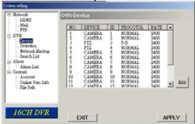
① Select the desired channel of the installed external device.
Press "Edit" to enter the setting box.
② Device Type: Choose either general camera or PTZ camera.
③ ID No. : Set the ID number (0 \~ 255) of the installed external PTZ device.
④ Protocol Type:
Choose "NORMAL" protocol for our own brand camera.
Choose "P-D" protocol for PELCO-D protocol camera.
⑤ Baud Rate : Set the baud rate of each channel (2400, 4800, 9600, 19200, 38400, 57600, 115200).
⑥ After setting, press "OK" and then press "APPLY" to confirm.
Take 16CH as an example
text_image
System setting Network DDNZ Mail FTP DVR Device Detection Network Backup Search List Alarm Alarm List General Account Online Users Info File Path 16CH DVR NO. DEVICE ID PROCOTOL RATE 1 CAMERA 1 NORMAL 2400 2 CAMERA 2 NORMAL 2400 3 PTZ 3 P-D 2400 4 PTZ 4 NORMAL 2400 5 CAMERA 5 NORMAL 2400 6 CAMERA 6 NORMAL 2400 7 CAMERA 7 NORMAL 2400 8 CAMERA 8 NORMAL 2400 9 CAMERA 9 NORMAL 2400 10 CAMERA 10 NORMAL 2400 11 CAMERA 11 NORMAL 2400 12 CAMERA 12 NORMAL 2400 Edit EXIT APPLY
text_image
EAd NO. DEVICE ID PROTOCOL RATE 1 CAMERA 1 NORMAL 2400 OKDetection
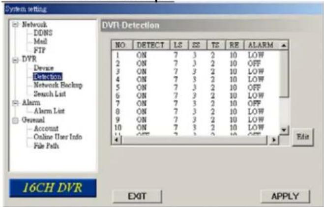
① Select the desired channel, and press "Edit" to enter the motion detection sensitivity and area setting box.
② Motion Detection Sensitivity:
Set the detection sensitivity in 4 different adjustable factors.
LS: The sensitivity of comparing two different images. The smaller the value is, the higher sensitivity for motion detection.
SS: The sensitivity towards the size of the triggered object on the screen (the number of motion detection grids). The smaller the value is, the higher sensitivity for motion detection.
TS: The sensitivity towards how long the object gets triggered. The smaller the value is, the higher sensitivity for motion detection.
RE: The value of RE is a reference for detection. The bigger the value is, the higher sensitivity for motion detection.
③ Alarm:
Select LOW / HIGH for the alarm polarity.
④ Motion Detection Area:
Clicking the area by PC mouse, one can choose the motion area to be detected. The under-detection area is in transparent picture while the undetected area is in pink color. *Click the "Select All" to clean the previously selected detection area. *Click the "Clear All" to activate the detection area as full area.
⑤ After setting, press "OK" and then press "APPLY" to confirm.
Take 16CH as an example
text_image
System setting Network DDNS Mail FTP DVR Devase Detection Network Backup Search List Alarm Alarm List General Account Online User Info File Path 16CH DVR DVR Detection NO DETECT LS SS TE RE ALARM 1 ON 7 3 2 10 LOW 2 ON 7 3 2 10 OFF 3 ON 7 3 2 10 LOW 4 ON 7 3 2 10 LOW 5 ON 7 3 2 10 OFF 6 ON 7 3 2 10 LOW 7 ON 7 3 2 10 OFF 8 ON 7 3 2 10 LOW 9 ON 7 3 2 10 LOW 10 ON 7 3 2 10 LOW 11 OFF 7 3 2 10 OFF Edit EXIT APLY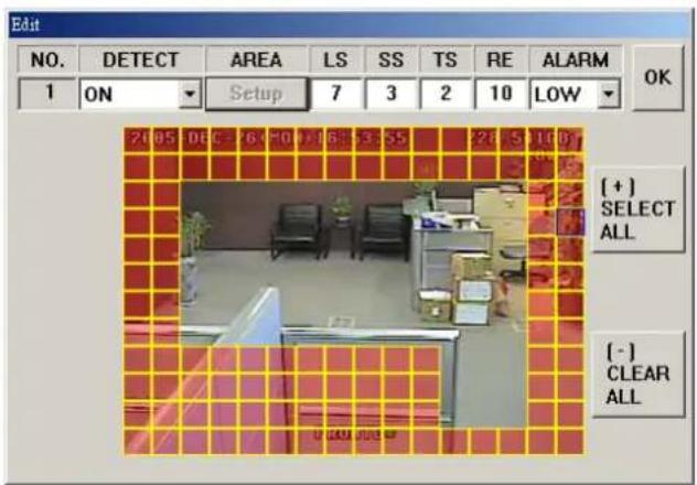
text_image
Edit NO. DETECT AREA LS SS TS RE ALARM OK 1 ON Setup 7 3 2 10 LOW [+] SELECT ALL [-] CLEAR ALL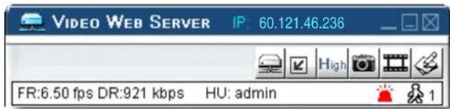
text_image
VIDEO WEB SERVER IP: 60.121.46.236 FR:6.50 fps DR:921 kbps HU: adminNote: Enable the motion detection function.
When the motion is triggered, a “ ”icon will shown on the screen. And software AP will start recording automatically.
Network Backup & Playback
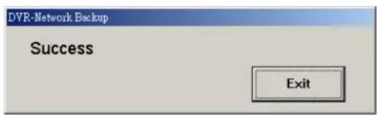
① Backup the recorded files to the PC from DVR via network.
② Enter the backup information → Press "Start" → Success → Covert → Play File.
text_image
DVR-Network Backup Success Exit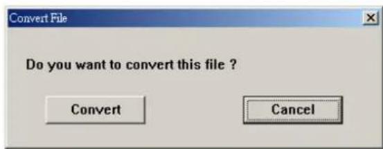
text_image
Convert File Do you want to convert this file ? Convert Cancel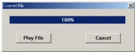
text_image
Convert File 100% Play File Cancel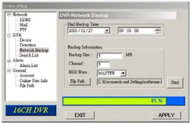
text_image
System setting Network DDNS Mail FTP DVR Device Detection Network Backup Search List Alarm Alarm List General Account Online User Info File Path 16CH DVR DVR-Network Backup Start Backup Time 2005/12/27 09:10:00 Backup Information Backup Size : $ MB Channel : $ HDD Num : MASTER File Path : C:\Documents and Settings\chatterase.1 Start 85 % EXIT APPLY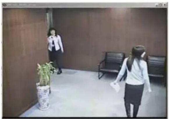
natural_image
Interior hallway scene with two women walking, a potted plant, and a bench (no visible text or symbols)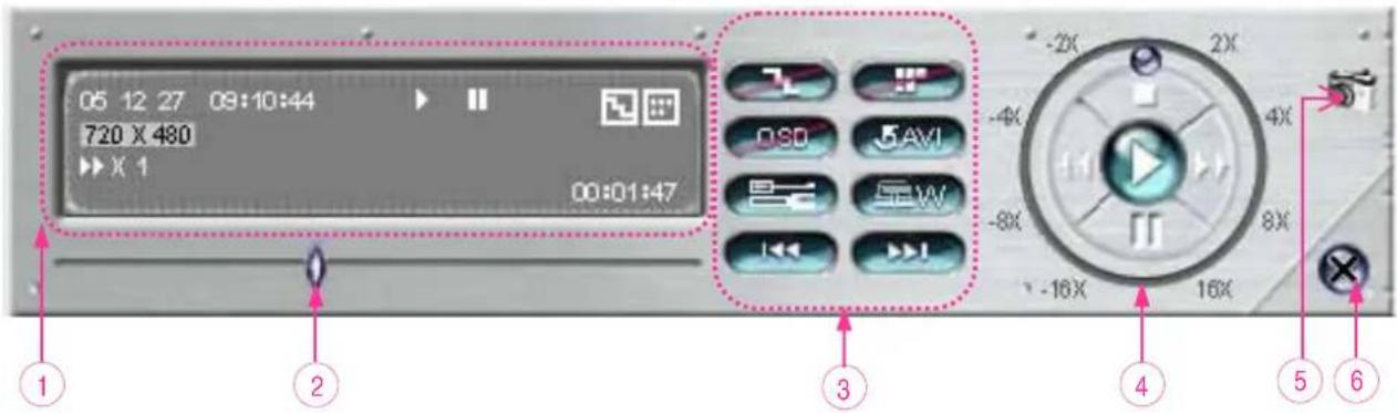
text_image
05 12 27 09:10:44 720 X 480 X 1 00:01:47 -2X 2X OSO 5 AVI SW -4X -8X 4X -16X 16X ① ② ③ ④ ⑤ ⑥- Playback Information
- Time Progress Bar
- Functions :
(1) De-interlace
(2) De-blocking
(3) OSD
(4) AVI Convert
(5) Config. Setting
(6) Watermark
(7) Open Previous
(8) Open Next File
- Playback Control Buttons :
Play / Stop / Pause / Fast Rewind / Fast Forward - Snapshot
- Close the Player.
***Note:***
While backup the file, users can see the live playback image at the same time.
Alarm
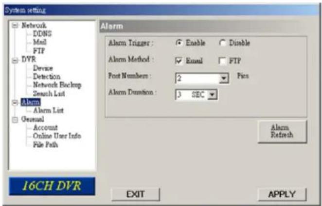
① Alarm Trigger: Enable or disable Email and FTP notification function.
② Alarm Method: Two notification methods — Email and / or FTP.
③ Post Number: Set MJPEG pictures (1-10 pictures).
④ Alarm Duration: Set the duration time of motion trigger recording (3 sec., 15 sec., 30 sec., 1 min., or 30 min.).
⑤ Alarm Refresh: Clean the alarm message "which is shown on the screen.
text_image
System setting Network DDNS Mail FTP DVR Device Detection Network Backup Search List Alarm Alarm List General Account Online User Info File Path Alarm Alarm Trigger : Enable Disable Alarm Method : Email FTP Post Numbers : 2 Pics Alarm Duration : 3 SEC Alarm Refresh 16CH DVR EXIT APPLYNote:
Email Notification:
MJPEG pictures will be made at your designated space set in "File Path", plus an e-mail contained with the MJPEG pictures (1-10 pictures) to be sent to the address which is set under "Mail".
FTP Notification:
MJPEG pictures will be made at your designated space set in "File Path", plus a FTP file contained with the MJPEG pictures (1-10 pictures) to be sent to the address which is set under "FTP".
Alarm List
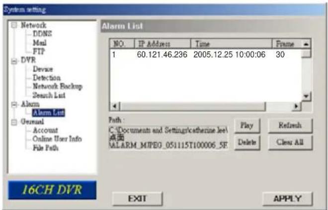
① It's a database, which precisely lists all alarm triggered events, with IP address of Video Web Server, alarm triggered time, and number of frames.
② Users could directly play, delete, or clear all motion trigger recording events easily.
③ Click on the "Refresh" button to update the database list.
④ All the motion triggered files will be listed systematically for easily search.
text_image
System setting Network DDNS Mail FTP DVR Device Detection Network Backup Search List Alarm Alarm List General Account Online User Info File Path 16CH DVR Alarm List NO. IP Address Time Frame 1 60.121.46.236 2005.12.25 10:00:06 30 Path : C:\Documents and Settings\catherine.lee\ 桌面 MALAR_MIPEO_051115T100006_5E Play Refresh Delete Clear All EXIT APPLYGeneral
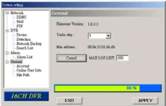
① Get the information of DVR firmware version in this window.
② Select "Turbo Step" (1 - 10).
To speed up menu selecting or the control of the PTZ camera under video web server, users can activate "Turbo" function by clicking this button. Users are allowed to change the turbo steps from 1 to 10.
Ex. If the value of turbo step is "5" means that when user press one of the button up/down/left/right, one click is as clicking 5 times.
③ Max Log List:
Set the maximum number of log list.
④ Server Log:
Press "Server Log" button to enter the server log list window.
text_image
System setting Network DDNS Mail FTP DVR Device Detection Network Backup Search List Alarm Alarm List General Account Online User Info File Path General Firmware Version: 1.0.3.5 Turbo step : 5 Mac address : 00.0e.53.01.b6.db Cancel MAX LOG LIST 300 80 % EXIT APPLY 16CH DVR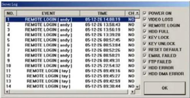
text_image
NO. EVENT TIME CH 1 REMOTE LOGIN [andy] 05-12-26 14:08:19 NO 2 REMOTE LOGIN [andy] 05-12-26 13:58:43 NO 3 REMOTE LOGIN [andy] 05-12-26 13:56:19 NO 4 REMOTE LOGIN [andy] 05-12-26 13:39:28 NO 5 REMOTE LOGIN [andy] 05-12-26 08:57:45 NO 6 REMOTE LOGIN [andy] 05-12-26 08:53:04 NO 7 REMOTE LOGIN [andy] 05-12-26 08:52:26 NO 8 REMOTE LOGIN [andy] 05-12-26 08:50:21 NO 9 REMOTE LOGIN [andy] 05-12-26 08:49:31 NO 10 REMOTE LOGIN [andy] 05-12-25 22:54:32 NO 11 REMOTE LOGIN [tay] 05-12-25 09:49:16 NO 12 REMOTE LOGIN [tay] 05-12-25 09:45:27 NO 13 REMOTE LOGIN [tay] 05-12-25 09:42:59 NO 14 REMOTE LOGIN [tay] 05-12-25 09:30:44 NO OKAccount
① Set up the user's account (Max 5 accounts), password, life time, and authority level. (Max 5 users on line at the same time).
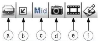
② User's level:
SUPERVISOR —
Control all the functions
("a", "b", "c", "d", "e" and "f").
HIGH —
Control only "a", "b", "c", "d" and "e" functions, but cannot control "f" function.
NORMAL —
Control only "a", "d", and "e" functions, but cannot control "b", "c" and "f" functions.
GUEST —
Watch the image only. Only the "a" function can be used.
③ Life time :
According to different authority level, different accounts can stay online for different time period (1min, 5min, 10min, 1hour, 1day, infinity).
text_image
Mid a b c d e f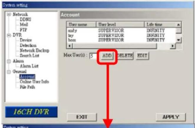
text_image
System setting Network DDNS Mail FIP DVR Device Detection Network Backup Search List Alarm Alarm List General Account Online User Info File Path 16CH DVR Account User name User level Life time andy SUPERVISOR INFINITY lay SUPERVISOR INFINITY box SUPERVISOR INFINITY Max User(s): 5 ADD DELETE EDIT EXIT APPLY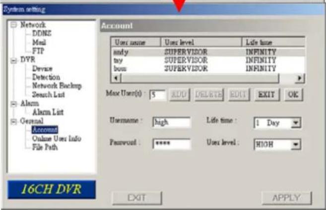
text_image
System setting Network DDNS Mail FTP DVR Devase Detection Network Backup Session List Alarm Alarm List General Account Online User Info File Path Account User name User level Life time andy SUPERVISOR INFINITY tax SUPERVISOR INFINITY box SUPERVISOR INFINITY Max User(s) : 5 XDU DELETE EDIT EXIT OK Username : high Life time : 1 Day Password : **** User level : HIOH 16CH DVR EXIT APPLYOnline User Info
① Get all the online users' information list (Name, IP Address, Authority Level, Resolution and Image Quality).
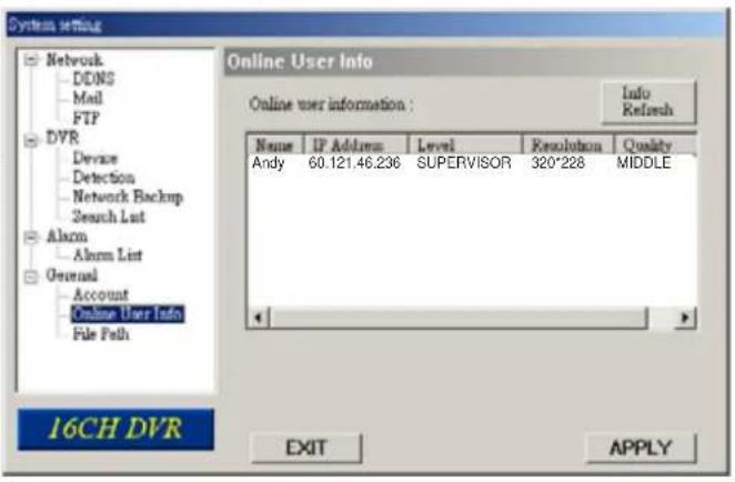
text_image
System setting Network DDNS Mail FTP DVR Devase Detection Network Backup Search List Alarm Alarm List General Account Online User Info File Path 16CH DVR Online User Info Online user information : Info Refresh Name IP Address Level Resolution Quality Andy 60.121.46.236 SUPERVISOR 320*228 MIDDLE EXIT APPLYFile Path
① Snapshot Path: Assign the route for saving the snapshot picture.
② Record Path: Assign the route for saving the manual recording file.
③ Alarm Audio Path:
The default alarm audio sound is "alarm.wav". Users could have their own alarm sound file by giving the file path.
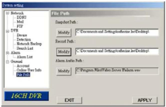
text_image
System setting Network DDNS Mail FTP DVR Device Detection Network Backup Search List Alarm Alarm List General Account Online User Info File Path 16CH DVR File Path Snapshot Path : Modify C:\Documents and Settings\katherine.lee\Desktop\ Record Path : Modify C:\Documents and Settings\katherine.lee\Desktop\ Alarm Audio Path : Modify C:\Program Files\Video Server\Alarm.wav EXIT APPLY5.7 CONNECT TO AP VIA IE BROWSER
The DVR can be viewed over the network with a web browser. Please install licensed software AP first.
*** This function is suitable in both Windows 2000 and Windows XP ***
Step 1: Type in IP address into the URL address box and press enter. Then you'll see the following page.
Note: If the TCP port number is not 80, see the example below.
IP address: 60.121.46.236 ; Port number: 888
→ Key in "http://60.121.46.236 :888" into the URL address box and press enter.
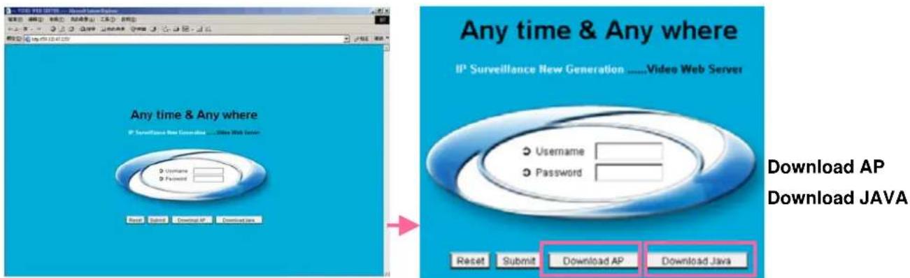
text_image
Any time & Any where IP Surveillance New Generation ....Video Web Server Username Password Reset Submit Download AP Download Java Any time & Any where IP Surveillance New Generation ....Video Web Server Username Password Reset Submit Download AP Download JavaNOTE: Users can download the latest AP version from the website.
NOTE: Users can update the JAVA program from the website.
Step 3: Key in the "username" and "password". Then you'll see the following page to login
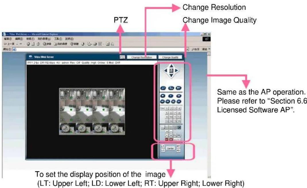
text_image
PTZ Change Resolution Change Image Quality Same as the AP operation. Please refer to "Section 6.6 Licensed Software AP". To set the display position of the image (LT: Upper Left; LD: Lower Left; RT: Upper Right; Lower Right)5.8 GPRS
GPRS function Installation and Viewing (Take Motorola 768i for example)
1) Your mobile service provider must have GPRS service, and the phone handset needs to support GPRS and Java MIDP 2.0 to run the application.
2) Connect to the website http://211.22.74.18 via the web browser of your cell phone. (Make sure that your GPRS function is working).
3) Download and install "16CH_MPEG-4" / "8CH_MPEG-4" / "4CH_MPEG-4".
4) After installation, the "16CH_MPEG-4" / "8CH_MPEG-4" / "4CH_MPEG-4" icon will shown on the desktop of the phone.
5) Click the icon of the "16CH_MPEG-4" / "8CH_MPEG-4" / "4CH_MPEG-4" video server to enter the setting frame.
Please type in IP address, port, username, and password of the DVR, which you like to see. And then press "connect" button.
6) After connected to the "16CH_MPEG-4" / "8CH_MPEG-4" / "4CH_MPEG-4" video server, you will see AP interface shown on the screen and will see "Online" on title.
7) Wait 3 minutes for video signal to coming out.
8) After video signal is shown, you could monitor and control your security system handily anytime, anywhere.
NOTE: It's not suggested to set the DVR port as 80 port. Because some telecommunication service provider may regulate 80 port.
5.9 OPTIONAL PERIPHERALS
For the operation of the following peripherals, please refer to their manual individually.
1) IDA (independent disk array).
2) VGA connector.
3) For 4CH DVR, IR Remote Control is optional.
TROUBLE SHOOTING
6.1 FAQ
Please refer to the FAQ table below for easy trouble shooting. The table below describes some typical problems and also their solutions. Please check them before calling your DVR dealer.
| SOLUTIONPROBLEM | |
| Check power cord connection.No power | |
| Confirm that there is power at the outlet. | |
| Not working when pressing any button | Press any key and then enter the password to exit “Key Lock” mode. |
| Timer record is not working | Check if the “RECORD ENABLE” is set to “YES”. |
| Check camera video cable and connections.No live video | |
| Check monitor video cable and connections. | |
| Confirm the camera is power supplied. | |
| Check the setting of camera lens. | |
| Check if the HDD is installed and connected properlyNo recorded video | |
| DVR keeps rebooting | Users could align the power connector and HDD closely, or change another suitable HDD. |
| Change another HDD for testing.Detect HDD fail | |
| Change another HDD cable for testing. | |
| Make sure HDD “Master”, “Slave” mode is correctly set. | |
| Change another USB thumb-drive to test.Can’t detect USB thumb-drive | |
| When two Seagate’s power-saving HDDs installed, DVR can’t be turned on successfully. | Please don’t use 2 Seagate’s power-saving HDDs simultaneously. |
| Can’t view the DVR over the network with a web browser | Update the JAVA programUpdate the firmware of the software AP |
APPENDIX #1 - INSTALL THE HDD
DMR - 516 / 508
16CH (D) / 8CH (D) / 4CH (D)
Carefully following the steps to ensure correct installation.
*** Note: If you want to install two HDDs, please set one HDD to "Master Mode" or "Single Mode", and the other one to "Slave Mode". ***
1) Open the upper cover of the DVR and screw out the bracket. 1 \~ 2
2) Screw HDD to the HDD bracket. 3 \~ 8
3) Connect the HDD to power connector and IDE BUS (make sure to align the HDD precisely to the pin connection). 9 \~ 14
4) Close the upper cover of the DVR.
natural_image
Close-up of hands working on a green circuit board with electronic components (no visible text or symbols)
natural_image
Close-up of hands assembling electronic components on a green circuit board (no visible text or symbols)
natural_image
Close-up of hands holding a white electronic device with a small black tool nearby (no visible text or symbols)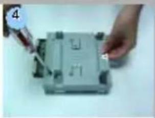
natural_image
Close-up of hands using a tool to adjust or install a component on a base (no visible text or symbols)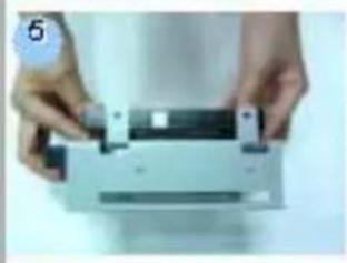
natural_image
Close-up of hands holding a white electronic device with a black clip, no visible text or symbols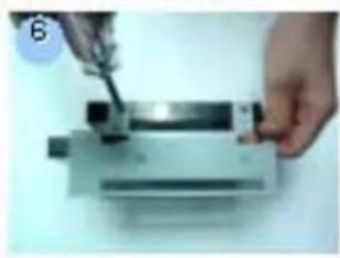
natural_image
Close-up of hands using a tool to apply material to a mechanical component (no visible text or symbols)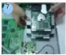
natural_image
Close-up of hands assembling electronic circuit boards on a workbench (no visible text or symbols)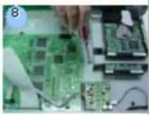
natural_image
Close-up of hands operating a green circuit board with electronic components (no visible text or symbols)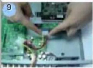
natural_image
Close-up of hands assembling electronic components on a circuit board (no visible text or symbols)
natural_image
Close-up of hands assembling electronic components on a circuit board (no visible text or symbols)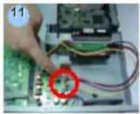
natural_image
Close-up of a hand connecting electronic circuit boards to a component, with wires and a red circle highlighting a specific part (no visible text or symbols)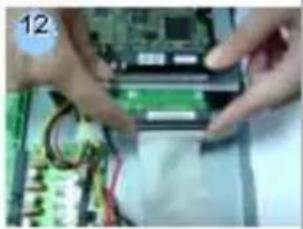
natural_image
Close-up of hands installing or adjusting a circuit board with wires and components (no visible text or symbols)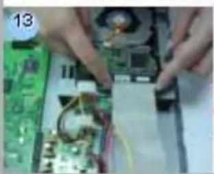
natural_image
Close-up of hands assembling electronic components on a circuit board (no visible text or symbols)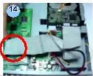
natural_image
Close-up of an electronic circuit board with visible traces and components (no readable text or symbols)DMR-504
Carefully following the steps to ensure correct installation.
*** Note: Please set one HDD to "Master Mode" or "Single Mode" ***
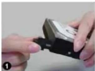
natural_image
Close-up of hands holding a small electronic device with a black handle (no visible text or symbols)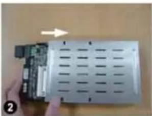
natural_image
Close-up of a hand holding an electronic device with a circuit board and ventilation grille (no visible text or symbols)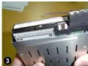
natural_image
Close-up of a handheld electronic device with visible ports and a metallic casing (no text or symbols)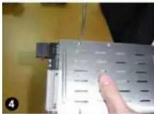
natural_image
Close-up of a hand holding a metallic electronic device with ventilation slots and a small connector (no visible text or symbols)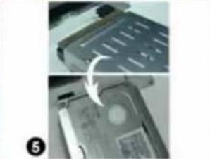
natural_image
Close-up of a computer hard drive showing internal components and a close-up view (no text or symbols visible)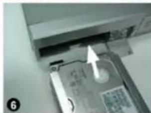
natural_image
Close-up of a computer hard drive showing internal components and a white arrow pointing to the drive (no visible text or symbols)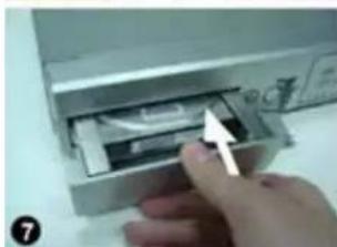
natural_image
Close-up of a hand inserting a device into a plastic container (no visible text or symbols)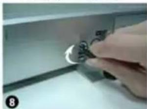
natural_image
Close-up of a hand pressing down on a metallic component with a knob (no visible text or symbols)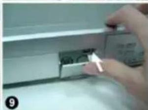
natural_image
Close-up of a hand inserting a small electronic component into a device (no visible text or symbols)- Step 1 Connect the connector with the HDD (refer to Picture 1).
- Step 2 Put HDD into the HDD cartridge. Please notice the bottom side is power side as chart shows (refer to Picture 2).
- Step 3 Screw the HDD to the cartridge. Before you screw the HDD, please be aware that you must to level pin 1 of the HDD at pin 1 mark, because the screw hole is different from different HDD brands. Then screw the HDD correctly (refer to Picture 3 and 4). You must precisely align the hard disk to the pin connection to ensure correct installation.
- Step 4 Reverse the HDD and put it into DVR (refer to Picture 5 and 6).
- Step 5 Connect the HDD with DVR (refer to Picture 7).
- Step 6 Lock the cabinet by turning the key clockwise (refer to Picture 8).
A (locked)
B ( unlocked )
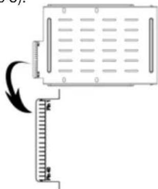
text_image
Diagram showing a device with a spring scale and directional arrow indicating motion or force, alongside a vertical ruler for measurement.Note : If you do not lock the cabinet, the DVR system will not function properly.
- Step 7 Close the cap (refer to Picture 9).
APPENDIX #2 - PIN CONFIGURATION
DMR - 516 / 508
16CH (D) / 8CH (D) / 4CH (D)
PIN 1. GND
GROUND
PIN 2. \~ PIN 9. ALARM INPUT
To connect wire from ALARM INPUT (PIN 2 -- 9) to GND (PIN 1) connector,
DMR will start recording and buzzer will be on.
When Menu/ Camera/ Alarm is set up to "Low": When alarm input signal is "Low", the unit starts to record and buzzer.
When Menu/ Camera/ Alarm is set up to "High": When alarm input signal is "High", the unit starts to record and buzzer.
PIN 10. PIN OFF
PIN 11. TXD232
DVR can be controlled remotely by the keyboard of PC, using RS-232 serial communications signals.
PIN 12. RS485-A
DVR can be controlled remotely by the keyboard of PC, using RS-485 serial communications signals.
PIN 13. EXTERNAL ALARM NO.
Under normal operation COM disconnect with NO. But when Alarm triggered, COM connect with NO.
Attention: Voltage restrictions is under AV/DC 30V.
PIN 14. PIN OFF
PIN 15. \~ PIN 22. ALARM INPUT
To connect wire from ALARM INPUT (PIN 15 -- 22) to GND (PIN 1) connector,
DMR will start recording and buzzer will be on.
When Menu/ Camera/ Alarm is set up to "Low": When alarm input signal is "Low", the unit starts to record and buzzer.
When Menu/ Camera/ Alarm is set up to "High": When alarm input signal is "High", the unit starts to record and buzzer.
PIN 23. RXD232
DVR can be controlled remotely by the keyboard of PC, using RS-232 serial communications signals.
PIN 24. RS485-B
DVR can be controlled remotely by the keyboard of PC, using RS-485 serial communications signals.
PIN 25. EXTERNAL ALARM COM
Under normal operation COM disconnect with NO. But when alarm triggered, COM connect with NO.
Attention: Voltage restrictions is under AV/DC 30V.
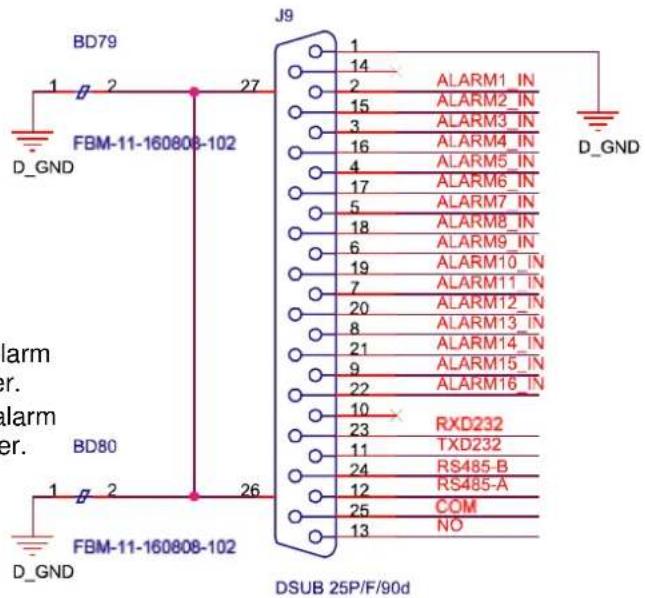
text_image
BD79 1 2 27 J9 FBM-11-160808-102 D_GND J9 14 2 ALARM1_IN 15 ALARM2_IN 3 ALARM3_IN 16 ALARM4_IN 4 ALARM5_IN 17 ALARM6_IN 5 ALARM7_IN 18 ALARM8_IN 6 ALARM9_IN 19 ALARM10_IN 7 ALARM11_IN 20 ALARM12_IN 8 ALARM13_IN 21 ALARM14_IN 9 ALARM15_IN 22 ALARM16_IN 10 RXD232 23 TXD232 11 RS485-B 24 RS485-A 12 COM 25 NO 13 D_GND BD80 FBM-11-160808-102 DSUB 25P/F/90dDMR 504
PIN 1. RS232-TX
DVR can be controlled remotely by the keyboard of PC, using RS-232 serial communications signals.
PIN 2. RS232-RX
DVR can be controlled remotely by the keyboard of PC, using RS-232 serial communications signals.
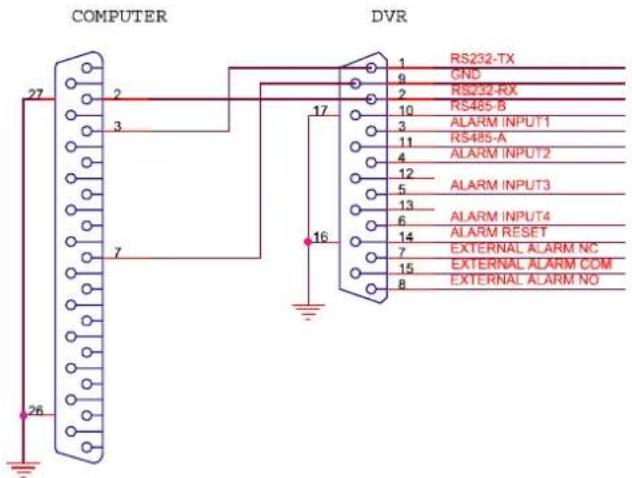
text_image
COMPUTER 27 2 3 7 26 17 16 DVR 1 RS232-TX 9 GND 2 RS232-RX 10 RS485-B 3 ALARM INPUT1 11 RS485-A 4 ALARM INPUT2 12 5 ALARM INPUT3 13 6 ALARM INPUT4 14 ALARM RESET 7 EXTERNAL ALARM NC 15 EXTERNAL ALARM COM 8 EXTERNAL ALARM NOPIN 3. \~ PIN 5. ALARM INPUT
To connect wire from ALARM INPUT (PIN 3 -- 5) to GND (PIN 9) connector, DVR will start recording and buzzer will be on.
When Menu/ Camera/ Alarm is set up to "Low": When alarm input signal is "Low", the unit starts to record and buzzer.
When Menu/ Camera/ Alarm is set up to "High": When alarm input signal is "High", the unit starts to record and buzzer.
PIN 7. EXTERNAL ALARM NC
Under normal operation COM connect with NC and disconnect from NO. But when alarm is triggered, COM disconnect with NC, and connect with NO.
Attention: Voltage restrictions is under AV/DC 30V.
PIN 8. EXTERNAL ALARM NO.
Under normal operation COM disconnect with NO. But when Alarm triggered, COM connect with NO. Attention: Voltage restrictions is under AV/DC 30V.
PIN 9. GND
Signal GND.
PIN 10. RS485-B
DVR can be controlled remotely by the keyboard of PC, using RS-485 serial communications signals.
PIN 11. RS485-A
DVR can be controlled remotely by the keyboard of PC, using RS-485 serial communications signals.
PIN 12, 13. PIN OFF
PIN 14. ALARM RESET
To connect wire from ALARM RESET (PIN 14) to GND (PIN 9) connector, it can disable ALARM. An external signal to
ALARM RESET (PIN 14) can be used to reset both ALARM OUTPUT signal and DVR's internal buzzer. When alarm has been triggered, signal becomes "Low", and it will stop all alarm activities. Under normal operation, signal remains "High".
PIN 15. EXTERNAL ALARM COM
Under normal operation COM disconnect with NO. But when alarm triggered, COM connect with NO. Attention: Voltage restrictions is under AV/DC 30V.
PIN 16, 17. GND
Earth GND
APPENDIX #3 - RS-232 Protocol
1) Use PC keyboard to simulate DVR keypad.
2) Data: REMOTE PROTOCOL use 8 bit data, 1 start bit, 1 stop bit.
| FUNCTION | CODE | ASCII | FUNCTION | CODE | ASCCI |
| KEY_MENU | 0x4D | M | KEY_CH1 | 0x31 | 1 |
| KEY_ENTER | 0x0D | ENTER | KEY_CH2 | 0x32 | 2 |
| KEY_4 CUT | 0x61 | a | KEY_CH3 | 0x33 | 3 |
| KEY_ZOOM | 0x5A | z | KEY_CH4 | 0x34 | 4 |
| KEY_9 CUT | 0x62 | b | KEY_CH5 | 0x35 | 5 |
| KEY_16 CUT | 0x63 | c | KEY_CH6 | 0x36 | 6 |
| KEY_SLOW | 0x53 | S | KEY_CH7 | 0x37 | 7 |
| KEY_REC | 0x72 | r | KEY_CH8 | 0x38 | 8 |
| KEY_LEFT | 0x4C | L | KEY_CH9 | 0x39 | 9 |
| KEY_UP | 0x55 | U | KEY_CH10 | 0x41 | A |
| KEY_PLAY | 0x50 | P | KEY_CH11 | 0x42 | B |
| KEY_DOWN | 0x4E | N | KEY_CH12 | 0x43 | C |
| KEY_RIGHT | 0x52 | R | KEY_CH13 | 0x44 | D |
| KEY_POWER | 0x57 | W | KEY_CH14 | 0x45 | E |
| KEY_KEY_LOCK | 0x4B | K | KEY_CH15 | 0x46 | F |
| G0x47KE |
APPENDIX #4 - RECORDING TIME TABLE
Take 16CH as an example
1) Recording time varies depending on the following factors:
* Different camera quality
* Different picture composition (such as frequency of the object movement)
2) Record day for 8CH: please multiply "Record day" by 2.
Record day for 4CH: please multiply "Record day" by 4.
| Record mode | Quality IPS | 500GB record time(hour) | Record day | |
| Frame Best | 120 109 | 4.6 | ||
| 60 192 | 8.0 | |||
| 30 349 | 14.6 | |||
| 15 565 | 23.5 | |||
| High | 120 138 | 5.8 | ||
| 60 243 | 10.1 | |||
| 30 442 | 18.4 | |||
| 15 714 | 29.8 | |||
| Normal | 120 182 | 7.6 | ||
| 60 319 | 13.3 | |||
| 30 581 | 24.2 | |||
| 15 939 | 39.1 | |||
| Basic | 120 293 | 12.2 | ||
| 60 516 | 21.5 | |||
| 30 939 | 39.1 | |||
| 15 1517 | 63.2 | |||
| CIF Best | 480 130 | 5.4 | ||
| 240 229 | 9.5 | |||
| 120 417 | 17.4 | |||
| 60 673 | 28.0 | |||
| High | 480 184 | 7.6 | ||
| 240 323 | 13.4 | |||
| 120 587 | 24.5 | |||
| 60 949 | 39.5 | |||
| Normal | 480 242 | 10.1 | ||
| 240 424 | 17.7 | |||
| 120 773 | 32.2 | |||
| 60 1249 | 52.0 | |||
| Basic | 480 335 | 13.9 | ||
| 240 588 | 24.5 | |||
| 120 1071 | 44.6 | |||
| 60 1730 | 72.1 | |||
APPENDIX #5
APPENDIX #5 - COMPATIBLE USB BRAND
NOTE: Please upgrade the Firmware of the DVR to latest version to ensure the accuracy of following table
| Manufacturer | Model | Capacity |
| Transcend | 256MBJetFlas | |
| Transcend | 512MBJetFlas | |
| Kingston | 256MBDataTr | |
| Kingston | 512MBDataTr | |
| PQI | 256MBCool D | |
| PQI | 512MBCool D | |
| Apacer | 256MBHAND | |
| Apacer | 512MBHAND | |
| SanDisk | 128MBCruzer | |
| SanDisk | 256MBCruzer | |
| 512MBCruzer |
sh 110
sh 110
aveler D
aveler D
rive (U3:
rive (U3;
/ STEN(
/ STEN(
Micro
Micro
MicroSa
APPENDIX #6
APPENDIX #6 - COMPATIBLE HDD BRAND
NOTE: Please upgrade the Firmware of the DVR to latest version to ensure the accuracy of following table
| Brand Name | Model | Capacity | Rotation |
| HITACHI | Deskstar HDS728080PLAT20 | 80GB | 7200 rpm |
| HITACHI | 7200 rpm120GB | ||
| HITACHI | Deskstar 7K250, HDS722516VLAT20 | 160GB | 7200rpm |
| HITACHI | HDS722516VLAT80 | 160GB | 7200rpm |
| 160GB | 7200rpmHDS722516DLA | ||
| HITACHI | 250GB | 7200rpmDeskstar 7K250, | |
| HITACHI | 7200rpm500GB | ||
| IBM | Deskstar 120GXP (80GB) | 80GB | 7200 rpm |
| IBM | Deskstar 120GXP (120GB) | 120GB | 7200 rpm |
| Maxtor | DiamondMax 536DX(60GB) 4W060H4 | 60GB | 5400rpm |
| Maxtor | DiamondMax Plus 9 | 80GB | 7200 rpm |
| Maxtor | DiamondMax Plus 9, Model#6Y120L | 120GB | 7200 rpm |
| Maxtor | DiamondMax Plus 9, Model#6Y160L0 | 160GB | 7200rpm |
| Maxtor | 7200rpm120GB | ||
| Maxtor | DiamondMax 10 6L160R0 | 160GB | 7200rpm |
| Maxtor | DiamondMax 10 6L200R0 | 200GB | 7200rpm |
| Maxtor | DiamondMax 10 6L200PO | 200GB | 7200rpm |
| Maxtor | MaxLine Plus II, Model#7Y250P0 | 250GB | 7200rpm |
| Maxtor | 7200rpm250GB | ||
| Seagate | Barracuda ATA IV, ST380021A | 80GB | 7200rpm |
| Seagate | Barracuda ATA V, ST3120023A | 120GB | 7200 rpm |
| Seagate | Barracuda 7200.7 Plus, ST3160023A | 160GB | 7200 rpm |
| Seagate | Barracuda 7200.8 ST3200826A | 200GB | 7200 rpm |
| Seagate | Barracuda 7200.8 ST3250826A | 250GB | 7200 rpm |
| Seagate | 7200 rpm300GB | ||
| Seagate | 7200 rpm400GB | ||
| Western Digital | Caviar WD1200BB-00CAA1 | 120GB | 7200rpm |
| Western Digital | 7200rpm120GB | ||
| Western Digital | Caviar SE WD1600JB | 160GB | 7200rpm |
| Western Digital | Caviar WD2000BB-00DWA0 | 200GB | 7200rpm |
| Western Digital | CaviarSE WD2500JB | 250GB | 7200rpm |
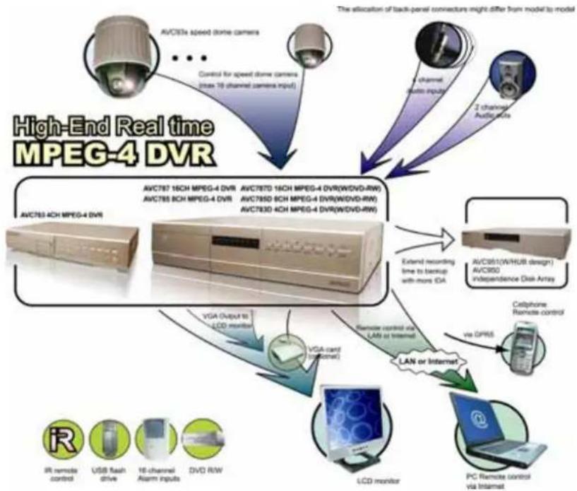
flowchart
graph TD
    A["AVC783 4CH MPEG-4 DVR"] --> B["AVC787 16CH MPEG-4 DVR"]
    B --> C["AVC787D 16CH MPEG-4 DVR(W/DVD-RW)"]
    C --> D["AVC785 8CH MPEG-4 DVR"]
    D --> E["AVC785D 6CH MPEG-4 DVR(W/DVD-RW)"]
    E --> F["AVC783D 4CH MPEG-4 DVR(W/DVD-RW)"]
    F --> G["AVC3951(W/HUB design) AVC3950 independence Disk Array"]
    G --> H["CLDN monitor"]
    H --> I["LCD monitor"]
    I --> J["PC Remote control via Intemat"]
    J --> K["Phone Remote control via Intemat"]
    L["VR remote control"] --> M["USB flash drive"]
    M --> N["16-channel Alarm inputs"]
    N --> O["DVD R/W"]
    P["Control for speed"] --> Q["(max 10 channel camera input)"]
    Q --> R["AVC395x speed dome camera"]
    S["The allocation of back-panel connectors might differ from model to model"] --> T["4 channel audio inputs"]
    T --> U["2 channels AVICbrance"]
    V["VGA Output to LCD monitor"] --> W["VGA card (optional)"]
    W --> X["LAN or Internet"]
    Y["Extended recording time to backup with more iDA"] --> Z["Cellphone Remote control"]
    Z --> AA["via OPMS"]