Tancan 4000 - Solarium Dr. Kern - Free user manual and instructions
Find the device manual for free Tancan 4000 Dr. Kern in PDF.


User questions about Tancan 4000 Dr. Kern
0 question about this device. Answer the ones you know or ask your own.
Ask a new question about this device
Download the instructions for your Solarium in PDF format for free! Find your manual Tancan 4000 - Dr. Kern and take your electronic device back in hand. On this page are published all the documents necessary for the use of your device. Tancan 4000 by Dr. Kern.
USER MANUAL Tancan 4000 Dr. Kern
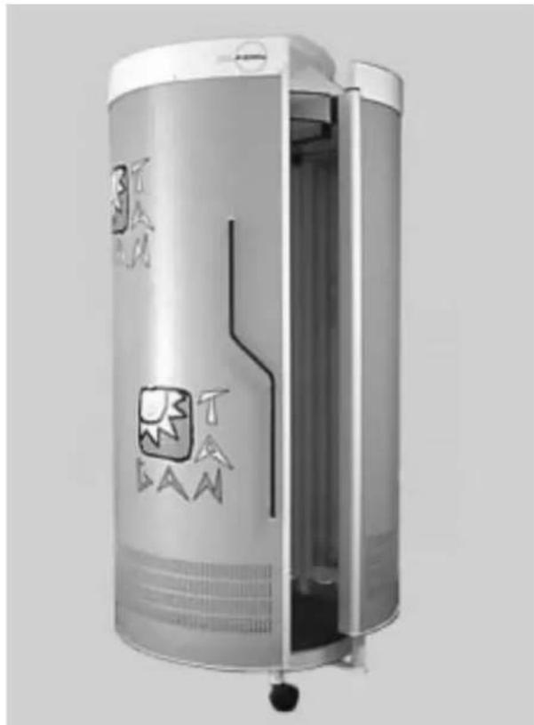
INSTALLATION AND USER'S GUIDE FOR SUNSHOWER
Tan Can 4000 Tan Can 8000
natural_image
Exterior view of a cylindrical industrial device with internal components and branding (no readable text or symbols)Contents
Please note! 3
Interesting facts about tanning 3
General safety precautions 3
Tanning times 4
Tanning program 4
After tanning....4
System installation 5
Operation 9
Operation via external timer control 9
Modification to coin box operation 11
Resetting to timer operation.... 11
Freeze the appointed time....11
Timer adjustment ....11
Cleaning the sunshower and the acrylic plates 12
Replacing UV tubes and starters 12
System exhaust configuration 12
Technical specifications 12
Warranty 13
Dear Customer,
With your purchase of a Dr. KERN tanning system, you have opted for a technically superior, high-performance unit. Our production staff has made every effort to ensure the reliable, trouble-free operation of your Dr. KERN system.
There is also a great deal that you can do to enhance your satisfaction and extend the life of your tanning system. Please read the User's Guide carefully and install the equipment in accordance with the installation instructions enclosed. Proper installation is essential to flawless tanning system performance.
Please note!
The tanning system is designed for a fixed connection with separator to a 380-400 V 3NAC power outlet (or for a CEE plug connector). In the event of power cable replacement, only type H05W-5 FG 1.5 ^2 cable may be used.
The tanning system must be installed in a dry room and kept free of exposure to spray or drop moisture. Maximum relative humidity and room temperature should not exceed 70% and 28°C, respectively. Higher room temperatures generate higher temperatures on the bench surface and under the sun hood.
Air intake slots and hot air exhaust vents on the cooling fans must not be blocked or covered, as the system may otherwise overheat.
In case of fan failure-which results in unusual heating of the tanning appliance-turn the equipment off immediately.
Always disconnect the system from the power source when performing work on the system (replacement of tubes/bulbs and starters or cleaning operations).
Repairs to the tanning system may be carried out only by a locally certified electrician or by plant customer service personnel.
When installing the tanning system, please ensure that the floor has sufficient load-bearing capacity (min. 4.5 KN/m ^2 ). If the capacity is lower, the installer must furnish appropriate documentation.
The acrylic plates in the system have proven to be incompatible with several cosmetics and cleansers currently on the market. Compatibility with our product ECOCLEAN has been tested, and the use of these products is safe for the equipment. We assume no liability for damage to the acrylic plates caused by chemical products of other manufacturers.
Attention!
This unit has an exhaust air system which only works properly with an sufficient incoming and outgoing air. The warranty expires if the requirements will not be fulfilled.
Interesting facts about tanning
The radiation of the tanning units is of an optimal composition. The special lamps emit a particularly high proportion of mild UV-A tanning rays. This avoids sunburn while allowing the skin to tan in the shortest possible time.
Aside from the cosmetic effects, reasonable exposure to tanning rays can promote overall physical well-being and may, in addition, have a favorable influence on a variety of skin disorders. Persons with known health disorders, however, should always consult a physician prior to tanning. The tanning appliance can produce its optimal tanning effect only when normal preconditions which are required for tanning in sunlight are present. The radiation of the tanning appliance will have no tanning effect on persons whose skin does not tan in sunlight.
General safety precautions
UV appliances must not be used by persons who sunburn in sunlight without tanning their skin (Skin type I), persons who show a tendency to sunburn, children under 16 years of age, or by persons who have suffered from skin cancer or who have a tendency to do so.
The recommendations specific to the individual unit regarding the tanning times and radiation intervals must be observed.
Do not use the system if the time control unit is defective or the filter glass is broken.
Ultraviolet exposure (radiation) from the sun or from UV appliances can lead to damage to the skin or eyes. These biological effects depend on the type and quantity of exposure (radiation), as well as on the sensitivity of the skin of the individual.
The skin may exhibit sunburn after excessive tanning. Overly frequent repetition of ultraviolet tanning sessions with sunlight or UV appliances may lead to premature aging of the skin as well as to an increased risk of skin tumors.
Without the use of protective eyewear, eyes can become inflamed on the surface, and in certain cases excessive exposure to UV light may damage the retina. Many repeated tanning sessions may lead to the formation of grey cataracts.
Special care must be taken in cases of particular sensitivity of some individuals to ultraviolet radiation, as well as in cases where certain medications or cosmetics are being
Therefore, the following safety precautions must be observed:
After tanning
- Always use protective goggles.
- Remove cosmetics in time for tanning and do use any type of sunscreen agent.
It is advisable to apply a moisturizing lotion to the skin after tanning.
- Do not tan when taking medication which increases the sensitivity of the skin to ultraviolet radiation. If in doubt, consult a physician.
- Always leave a break of one day between tanning sessions and do not have a sunbath on the same day.
- Follow recommendations concerning tanning times, intervals and distances.
- Visit your physician if the skin displays persistent swelling, sores or pigmented moles.
Tanning Times
| Skin type Description Designation | Reaction to sunlight | Max. sunlight exposure time without protection | |||
| Sunburn Tanning | |||||
| I | Skin: extremely lightFreckles: very noticeableHair: reddishEyes: blue, seldom brownNipples: very light | Celtic type(2%) | only,severe,painful | none,reddening,turns white after 1-2 days, skin peels | 5-10minutes |
| II | Skin: somewhat darker than IFreckles: seldomHair: blonde to brownEyes: blue, green, brownNipples: light | light-skinnedEuropean(12%) | always,severe,painful | negligible,skinpeels | 10-20minutes |
| III | Skin: light to light brownFreckles: noneHair: dark blonde, brownEyes: grey, brownNipples: darker | dark-skinnedEuropean(78%) | moderate | averageseldom, | 20-30minutes |
| IV | Skin: light brown, oliveFreckles: noneHair: dark brownEyes: darkNipples: dark | Mediterraneantype(8%) | negligible | quickanddeep | 40minutes |
Tanning program
Using data which coordinates skin types with the radiation source integrated in your tanning system, a tanning program has been determined for your tanning system in accordance with the recommendations of EN 60-335-2-27. This program accompanies your tanning system as printed matter.
The beginning and maximum exposure times must not be exceeded.
System Installation
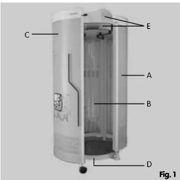
The system is delivered in several separately packed sections for transport to its final installation point. The complete package contains the following individual elements:
A right tanning element (package 3)
B. left tanning element (package 2)
C. door tanning element (package 1)
D. base
E. exhaust unit
text_image
C E A B D Fig. 1System assembly is described step by step in the following sections. Please ensure that electrical wiring and connection is performed by a certified electrician in keeping with VDU and local EVU regulations.
①Baseplate
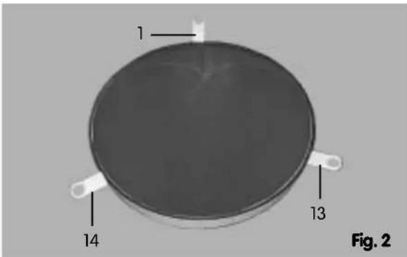
Begin the assembly by removing the baseplate (D) from package 4, and placing it at the intended location of the system.
Note:
The baseplate must be placed flat and level! For orientation purposes, the rear positioning tongue is provided with an adhesive label.
text_image
1 13 14 Fig. 2②Right tanning element
Remove the right element (A) from package 1. You must now carry out the initial assembly of the two stand feet.
Stand foot, facing side lower right:
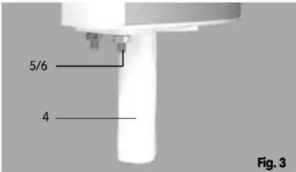
From the accessory pack, take the stand foot (4), two M10 nuts (5) and washers (6), and assemble the foot as shown in Fig. 3.
text_image
5/6 4 Fig. 3Stand foot, facing side lower left:
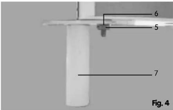
From the accessory pack, take the stand foot (7), two M10 nuts (5) and washers (6), and assemble the foot as shown in Fig. 4
text_image
6 5 7 Fig. 4Ensure that the installation plate of the stand foot is correctly positioned for connection to the next element (Fig. 4).
③Left tanning element
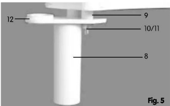
Remove the left element (B) from package 2, and assemble the stand foot (8) as follows:
From accessory pack 2, take 2 distance collars (9), two M10 nuts (10) and 2 lock-washers (11), and assemble as shown in Fig. 5.
Note: The bearing (12) for the door element is already fitted in stand foot (8).
text_image
12 9 10/11 8 Fig. 5④Installing the tanning elements preassembled in steps 2 and 3
Installation of the right element
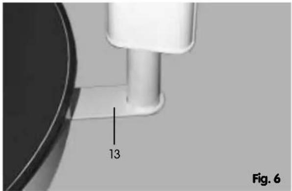
Lift the element and place it in the tongues provided (13 + 1) in the baseplate (Figs. 6 and 7).
Note!
The element will need to be held in place by one person.
text_image
13 Fig. 6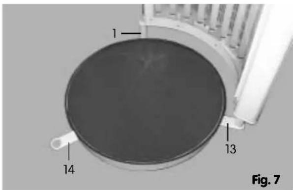
text_image
1 14 13 Fig. 7Installation of the left element
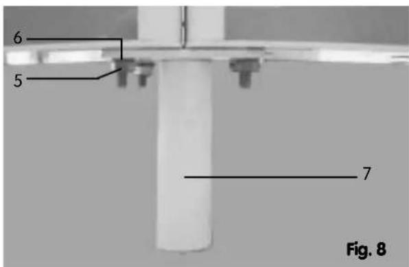
Lift the element and place the lower right side on the installation plate of the stand foot (7) (Fig. 8).
text_image
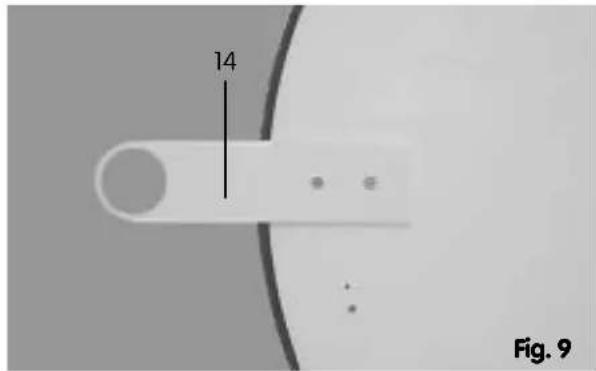
6 5 7 Fig. 8Now lift the stand foot (8) on the lower left side into the positioning tongue (14) in the baseplate (Fig. 9).
text_image
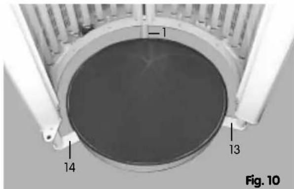
14 Fig. 9The current assembly condition is shown in Fig. 10.
text_image
1 13 14 Fig. 10Note! Both elements must be held in the upright position until they are bolted together.
Bolting together the two elements at stand foot (7). For this step, you will need two M10 nuts (5) and 2 lock-washers (6) from the accessory pack (Fig. 8).
Bolting together the two elements at the top
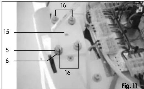
For this step, you will need the installation plate (15), 4 nuts (5) and 4 lock-washers (6) from the accessory pack.
M10 bolts (16) are provided in the upper sections of both elements. Place the installation plate with its holes over the bolts (16), and fix it firmly in place using the nuts (Fig. 11.
The two tanning elements are now assembled.
Note: Check the correct position in relation to the baseplate and the aligned position!
text_image
16 15 5 6 16 Fig. 11⑤Installation of the exhaust unit
Remove the following parts of the exhaust unit (E) from package 4:
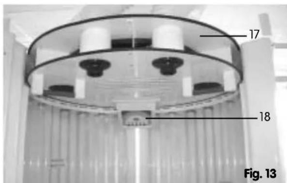
- Ceiling plate (17) with integral central fan and operating panel (18)
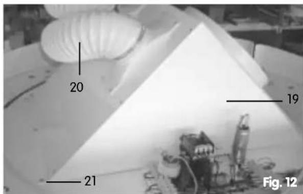
- Exhaust duct (19) with two bypass hoses (20)
These two parts must be bolted together. To do this, remove the pre-assembled bolts (21) from the ceiling plate (17), place the exhaust duct with its attachment holes in position on the ceiling plate, and then refit the bolts (21) (Fig. 12).
text_image
20 19 21 Fig. 12Note: The operating panel (18) must not be bolted to the lower plate yet!
The complete exhaust unit is now lifted onto the tanning elements (Fig. 13).
text_image
17 18 Fig. 13Now place the attachment holes in the exhaust unit over the matching holes in the tanning elements.
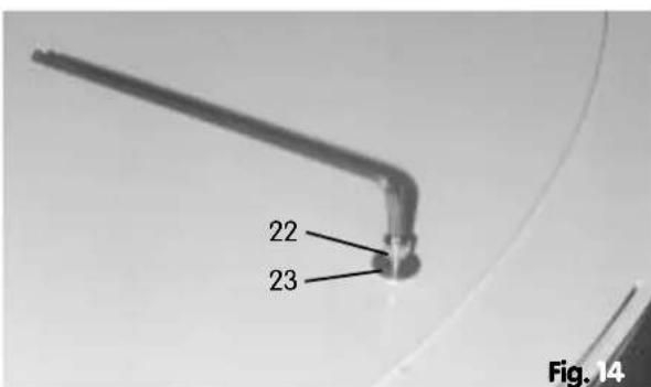
Use 6 hex-head bolts (22) with washers (23) from the accessory pack to bolt the exhaust unit in place (Fig. 14)
text_image
22 23 Fig. 14Now bolt the operating panel (18) to the lower ceiling plate (Fig. 13), using the bolts provided in the accessory pack.
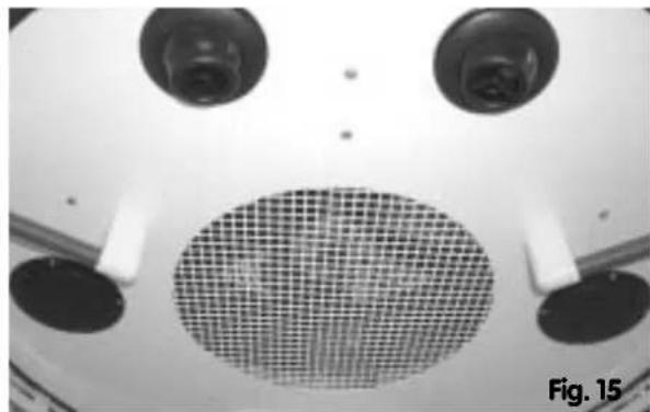
The following auxiliary elements are built into to ceiling plate of the TAN CAN 8000
- 2 air jets for the head area
- 2 loudspeakers for connection to an external audio system
- control unit
natural_image
Top-down view of a mechanical component with a grid-patterned grille and two circular ports (no text or symbols visible)⑥ Installing the door element
Remove the door element (C) from package 3.
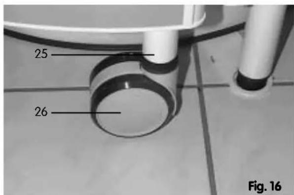
Note: The retaining bolt (25) for the castor, and the upper and lower bearings (27) and (32) are already fitted to the door element (Figs. 16 - 18).
text_image
25 26 Fig. 16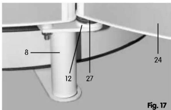
text_image
8 12 27 24 Fig. 17Now screw the castor (26) onto the retaining bolt (25) (Fig. 16).
Lift the door element with the pre-assembled bearing bolt (27) onto the installation plate (12), and slide the bearing into place.
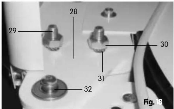
To assemble the upper bearing (Fig. 18), you will need the installation plate (28), which is first loosely assembled using the two threaded bolts (29), the nuts (30) and lock-washers (31).
Swing the door element over the installation plate (28) so that the upper bearing point of the door element (32) is positioned opposite the opening in the installation plate (28).
Now let the installation plate (28) drop down over the upper bearing, and tighten the two nuts (30) firmly (Fig. 18).
text_image
28 29 30 31 32 Fig. 18⑦ Electrical connection of the elements
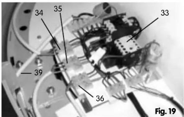
All 3 elements have their electrical connections at the top, and are connected to the control unit (33) by means of the 3 plugs (34 - 36) (Fig. 19).
text_image
34 35 33 39 36 Fig. 1933 = Control unit
34 = Connection cable, right element
35 = Connection cable, left element
36 = Connection cable, door element
39 = Main connection cable
⑧Installing the upper trim panels
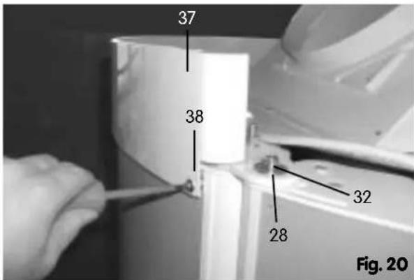
Finally, fit the three trim panels (37) around the upper edge of the system (Fig. 20), using for each panel two self-tapping screws (38) on the outside, and two M4 screws in the central area.
Ensure that a distance sleeve is placed between the trim panel and rear wall of the unit at each attachment point.
text_image
37 38 32 28 Fig. 20⑨Installation of main connection cable / cover panel
The main connection cable (39) is pre-assembled to the control unit (33), and lies rolled up on the exhaust unit.
Take the cable (39) and lead it down along the side of the system (Fig. 21).
Then fit the cable tension-relief device (40) (from the accessory pack) to the cable (Fig. 22).
Now remove the cover panel (41) from package 3, and fit it as shown in Fig. 23.
Note: The existing screws in the rear walls are used for the attachment of the cover panel (41). These screws must be removed before fitting the cover panel.

text_image
39 Fig. 21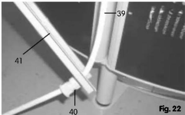
text_image
39 41 40 Fig. 22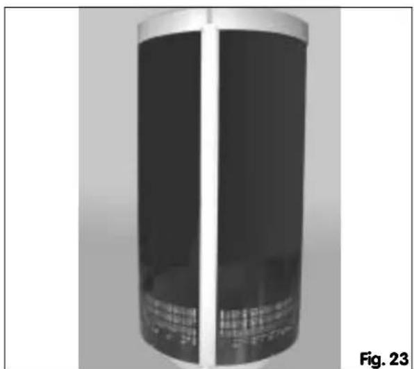
natural_image
Exterior view of a cylindrical mechanical component with metallic rim and internal structure (no visible text or symbols)Connect the main power cable to the mains power source using a fixed connection or a plug connection (CECON plug).
The system is now ready for operation.
Operation
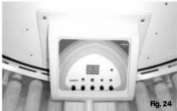
The tanning unit will be switched on by using the On/Off-switch ① (fig.) at the digital-timer.
With the keys ④ and ⑤ (fig. 25) you can select your tanning time (max. 30 minutes).
⑤=up, ④=down
After loose of time the digital timer of the tanning unit switches off automatically.
After tanning session the unit is switching over to after cooling mode for 3 minutes.
natural_image
Close-up of a medical imaging device with a digital display and control buttons, labeled 'Fig. 24' (no readable text or symbols on the device itself)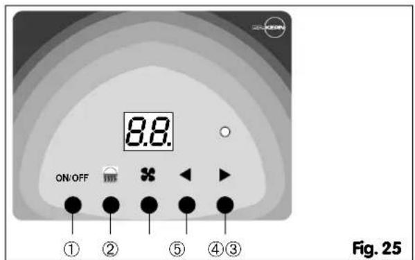
text_image
ON/OFF 8.8 ① ② ⑤ ④③ Fig. 25Attention: The switches ② and ③ are inoperable in this tanning appliance.
Operation via external timer control
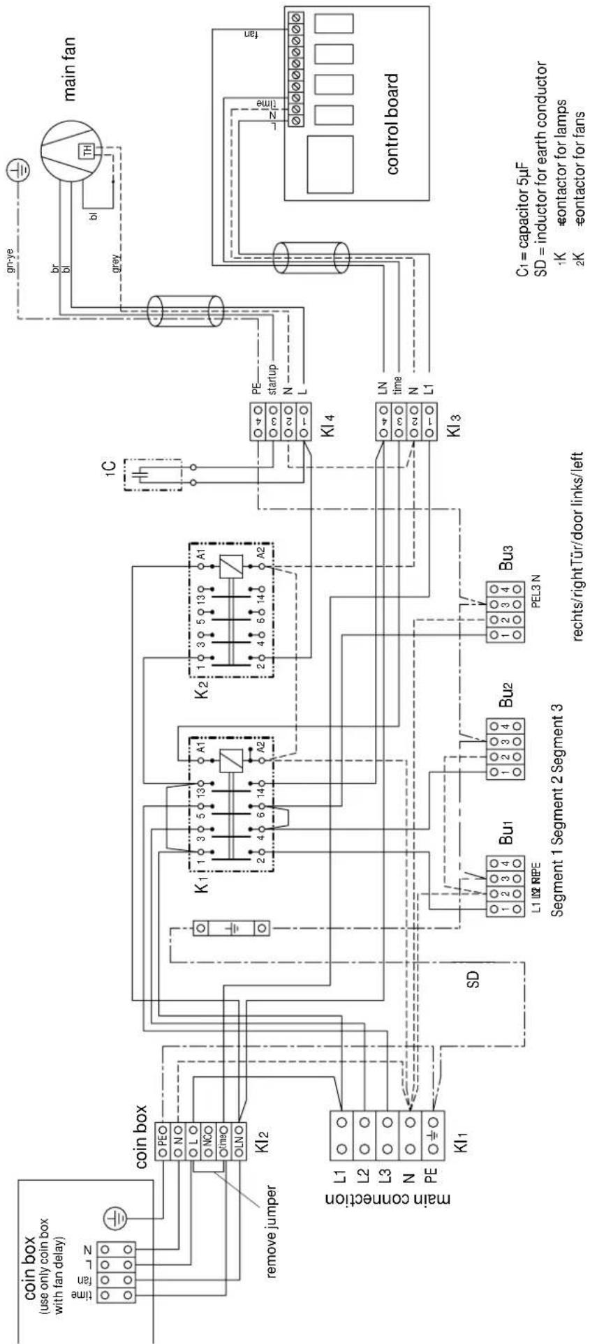
Further on you can use your tanning unit via external timer control (e.g. coin box). The connection is to be made according to the following wiring diagram.
Please pay attention, that a control line for the fan delay has to be available in either case.
The connection line between the application and the external timer control is inducted into the appliance besides the main connection line and applied to the connection terminal (fig.26).
flowchart
graph TD
    A["main fan"] --> B["control board"]
    B --> C["coin box (use only coin box with fan delay)"]
    C --> D["coin box"]
    D --> E["remove jumper"]
    E --> F["KI1"]
    F --> G["L1 L2 L3 N PE KI1"]
    G --> H["SD"]
    H --> I["L1 L2 RPE"]
    I --> J["Bu1"]
    J --> K["Segment 1 Segment 2 Segment 3"]
    K --> L["Bu2"]
    L --> M["PEL3 N"]
    M --> N["KI3"]
    N --> O["L1 L2 RPE"]
    O --> P["Bu1"]
    P --> Q["Segment 1 Segment 2 Segment 3"]
    Q --> R["Bu2"]
    R --> S["PEL3 N"]
    S --> T["KI4"]
    T --> U["PE startup N L"]
    U --> V["main connection"]
    V --> W["L1 L2 RPE"]
    W --> X["Bu1"]
    X --> Y["Segment 1 Segment 2 Segment 3"]
    Y --> Z["Bu2"]
    Z --> AA["PEL3 N"]
    AA --> AB["KI3"]
    AB --> AC["L1 L2 RPE"]
    AC --> AD["Bu1"]
    AD --> AE["Segment 1 Segment 2 Segment 3"]
    AE --> AF["Bu2"]
    AF --> AG["PEL3 N"]
    AG --> AH["KI4"]
    AH --> AI["L1 L2 RPE"]
    AI --> AJ["Bu1"]
    AJ --> AK["Segment 1 Segment 2 Segment 3"]
    AK --> AL["Bu2"]
    AL --> AM["PEL3 N"]
    AM --> AN["KI3"]
    AN --> AO["L1 L2 RPE"]
    AO --> AP["Bu1"]
    AP --> AQ["Segment 1 Segment 2 Segment 3"]
    AQ --> AR["Bu2"]
    AR --> AS["PEL3 N"]
    AS --> AT["KI4"]
    AT --> AU["L1 L2 RPE"]
    AU --> AV["Bu1"]
    AV --> AW["Segment 1 Segment 2 Segment 3"]
    AW --> AX["Bu2"]
    AX --> AY["PEL3 N"]
    AY --> AZ["KI3"]
    AZ --> BA["L1 L2 RPE"]
    BA --> BB["Bu1"]
    BB --> BC["Segment 1 Segment 2 Segment 3"]
    BC --> BD["Bu2"]
    BD --> BE["PEL3 N"]
    BE --> BF["KI4"]
    BF --> BG["L1 L2 RPE"]
    BG --> BH["Bu1"]
    BH --> BI["Segment 1 Segment 2 Segment 3"]
    BI --> BJ["Bu2"]
    BJ --> BK["PEL3 N"]
    BK --> BL["KI3"]
    BL --> BM["L1 L2 RPE"]
    BM --> BN["Bu1"]
    BN --> BO["Segment 1 Segment 2 Segment 3"]
    BO --> BP["Bu2"]
    BP --> BQ["PEL3 N"]
    BQ --> BR["KI4"]
    BR --> BS["L1 L2 RPE"]
Fig. 26
Modification to coin box operation
For this procedure 2 persons are needed.
- If the coinbox is not connected yet, separate the appliance completely from power supply.
●During one person keeps pushing simultaneously the up and down button at the timer, the other person is connecting the appliance to power supply again. - If the coinbox is already connected, the appliance must not be separated from the power supply. In this case follow the instructions below:
- one person keeps pushing simultaneously the up and down button at the timer.
- the other person starts running the coin box by throwing in a coin
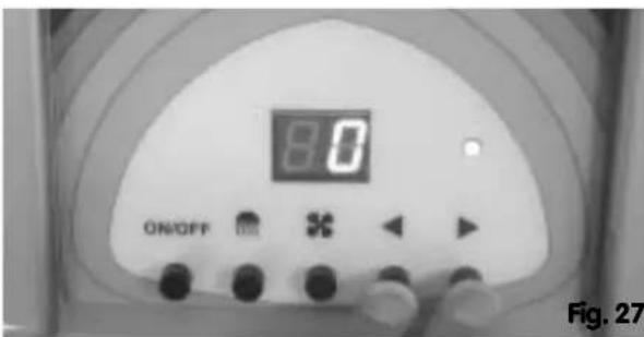
- Keep pushing the up and down button as long as „0“ appears on the timer display (fig. 27).
text_image
8.0 ON/OFF Fig. 27The appliance is now coin box operated.
After release by the coin box the timer is going from „0" minutes upwards.
The appliance can be started and stopped.
The up and down buttons are locked. The other buttons keep their function.
When the time is over, the appliance is completely switched off and the timer display expires.
Attention: The fan delay has to be executed by the coin box!
Resetting to timer operation
The resetting is only possible, if the coinbox is separated and the wire jumper "L1-Time" is mounted (see connection diagram on fig. 26).
For this procedure 2 persons are needed.
●Separate the appliance completely from power supply.
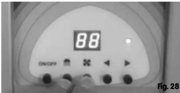
●During one person keeps pushing simultaneously the face tanner and body fan button at the timer, the other person is connecting the appliance to power supply again.
- Keep pushing the face tanner and body fan button as long as „88“ appears on the timer display (fig. 28).
● Afterwards the display expires.
text_image
88 ON/OFF Fig. 28The appliance is now timer operated.
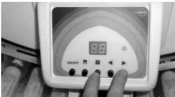
Freeze the appointed time
●Tune the favoured tanning time at the timer.
●Push the button "fan" and "upward" at the same time (fig. 29).
text_image
3.0 OFF/ONNow the sunbed is working as long as the appointed time is expired.
In between it is not possible to shift the time, the bottoms are blocked. But the sunbed can be switched off an on. By switching on again the balance time elapses. After run of time the sunbed cuts off and a new time can be set.
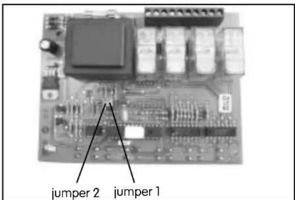
Timer adjustment
text_image
jumper 2 jumper 1jumper 1 (time period):
opened = maximum period 30 min
closed = maximum period 60 min
jumper 2 (fan delay)
opened = without fan delay
closed = with fan delay
Cleaning the sunshower and the acrylic plates
Use a moist cloth to clean the sunshower . The acrylic plates should also be cleaned at regular intervals. Use only solvent-free, non-caustic and non-aromatic cleaning agents.
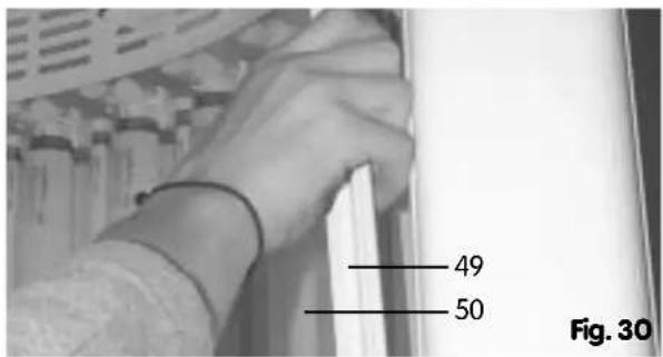
To remove the acrylic plates, pull each plate forward from its position, gripping the profile bars on the side (49) from behind as shown in Fig. 30. Bend the plate (50) slightly toward the inside. Then press the plate down and out of the mounting frame grooves on the sides. The plate can now be cleaned on both sides.
After cleaning, replace each plate in the following manner:
Set the lower edge of the plate on the pin (51), grip the side profile bars and press the outer edge of the plate (52) against one edge of the mounting frame.
Then bend the plate slightly toward the inside and press until the opposite edge locks into place on the other edge of the mounting frame. Fig. 31.
text_image
49 50 Fig. 30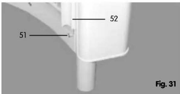
text_image
51 52 Fig. 31Replacing UV tubes and starters
To replace tubes and starters, first remove the acrylic plates as described above.
The UV tubes in your tanning system must be replaced after a certain number of operating hours.
The effective service life of the UV low-pressure tubes is about 500 hours. Please ensure that only original replacement parts are used when replacing tubes and starters. Replacement parts can be ordered from customer service or your local dealer. Please indicate the system number (see ID plate). This applies to orders for all replacement parts.
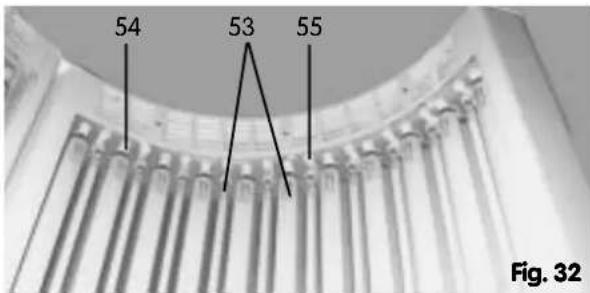
UVA low-pressure tubes (53) are removed/inserted by turning them 90° in their sockets (54) both above and below and pulling them forward. When inserting new tubes, please ensure that the contact pins on the tubes are fitted properly into the sockets.
Starters (55) are located at the upper ends of the tubes and are removed/inserted by turning them 90° and out of their sockets. Fig. 32.
text_image
54 53 55 Fig. 32System exhaust configuration
Exhaust air should be removed from your sunshower via a hose. Please take the following points into account with regard to the configuration of the exhaust system.
Outside temperature has a considerable impact on system operation. Ideally, outside temperature should be 28° with a relative humidity of 70%. Use only 300-mm hose for the exhaust line. Ideally, exhaust hose should lead in a straight line up and away from the cell. Bends in the hose generate air-flow resistance. Avoid 180° bends in all cases. Given a straight exhaust line configuration, exhaust hoses can be as long as 2 m without the need for an additional blower unit. If the exhaust line is longer than 2 m or has bends, the addition of an auxiliary blower unit is recommended in order to ensure effective exhaust air removal. Hose output diameter should not be reduced at any point in the exhaust line, as this may result in air blockage.
Technical Specifications
Tan Can 4000
Lamp tubes: 33 x 100 W UVA reflectorlamps
30 x 25 W spaghetti lamps
Nominal power output: 4700 W
Circuit breakers: 3 x 16 A
Nominal voltage: 3N AC 400 V
Power cable: 5 x 1,5 mm²
Dimensions:
Outside dimensions: ∅ 1.1 m, height 2.45 m
Inside dimensions: ∅ 0.88 m, height 2 m
Exhaust hose: ∅ 300 mm
Tan Can 8000
Lamp tubes: 48 x 160 W UVA reflector tubes
Nominal power output: 8500 W
Circuit breakers: 3 x 16 A
Nominal voltage: 3N AC 400 V
Power cable: 5 x 1.5 mm²
Dimensions:
Outside dimensions: ∅ 1,1 m, height 2,45 m
Inside dimensions: ∅ 0,88 m, height 2 m
Exhaust hose: ∅ 300 mm
Guarantee
The guarantee is taken over according to the legal regulations at present.
Manufacturer's warranty
The period of warranty starts from the date of purchase and lasts upto 12 months.
- Always include the completed warranty certificate when returning equipment.
- The warranty expires for appliances which have been modified without manufacturer's explicit agreement.
- Damages caused by incorrect operation or handling through non-authorized persons are not covered under the terms of warranty.
- In the event of a claim, please indicate the serial number as well as the article code number and type name with expressive description of the fault.
- This warranty covers damaged parts but no defects due to wear and tear.
In case of complaint please return the equipment in its original packaging or other suitable packaging (caution: danger of transport damage) to our service department.
Always include the completed warranty certificate when returning equipment. Possible shipping costs arising from the transport to and from point of repair cannot be borne by us. Always include the completed warranty certificate when returning equipment.
Outside of Germany please contact your specialist dealer in case of warranty claims. Direct warranty processing with our service department is in this case not possible.
Equipment start-up date:
Stamp and signature of the authorized electrician:
Service address:
DR. KERN GmbH
Please keep this address in a safe place together with the installation guide.
To help us answer your questions quickly and competently, please provide data printed on the ID plate, to include system type, article no. and serial no., in all inquiries.
Please note!
Waste Disposal Law of 27 August 1986
Tanning tubes require separate disposal measures as hazardous waste materials.
Local communities provide for disposal of tubes from private homes and commercial enterprises at designated hazardous-waste collection points.
Tubes must be delivered intact for disposal.