Leslie 2102 - Organ Hammond - Free user manual and instructions
Find the device manual for free Leslie 2102 Hammond in PDF.


User questions about Leslie 2102 Hammond
0 question about this device. Answer the ones you know or ask your own.
Ask a new question about this device
Download the instructions for your Organ in PDF format for free! Find your manual Leslie 2102 - Hammond and take your electronic device back in hand. On this page are published all the documents necessary for the use of your device. Leslie 2102 by Hammond.
USER MANUAL Leslie 2102 Hammond
"...music so beautiful that it has to be heard."
natural_image
Black-and-white illustration of a vintage portable radio with three speakers and a triangular antenna (no text or symbols)OWNER'S MANUAL
2101/
2102/
2103
Leslie
IMPORTANT SAFETY INSTRUCTIONS
Read these instructions.
Keep these instructions.
Heed all warnings.
Follow all instructions.
Do not use this apparatus near water.
Clean only with dry cloth.
Do not block any ventilation openings. Install in accordance with the manufacturer's instructions.
Do not install near any heat sources such as radiators, heat registers, stoves or other apparatus (including amplifiers) that produce heat.
Do not defeat the safety purpose of the polarized or grounding-type plug. A polarized plug has two blades with one wider than the other. A grounding type plug has two blades and a third grounding prong. The wider blade or third prong is provided for your safety. If the provided plug does not fit into your outlet, consult an electrician for replacement of the obsolete outlet.
Protect the power cord from being walked on or pinched, particularly at plugs, convenience receptacles, and the point where they exit from the apparatus.
Only use attachments/accessories specified by the manufacturer.
Unplug this apparatus during lightning storms, or when unused for long periods of time.
Refer all servicing to qualified service personnel. Servicing is required when the apparatus has been damaged in any way, such as power-supply cord or plug is damaged, liquid has been spilled or objects have fallen into the apparatus, the apparatus has been exposed to rain or moisture, does not operate normally, or has been dropped.
Apparatus shall not be exposed to dripping and splashing and no objects filled with liquids, such as vases, shall be placed on the apparatus.
WARNING: To reduce the risk of fire or electric shock, do not expose this apparatus to rain or moisture.
text_image
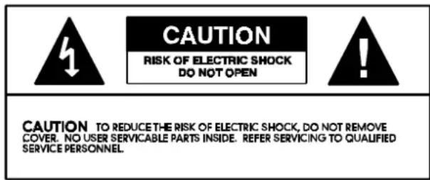
CAUTION RISK OF ELECTRIC SHOCK DO NOT OPEN CAUTION TO REDUCE THE RISK OF ELECTRIC SHOCK, DO NOT REMOVE COVER. NO USER SERVICABLE PARTS INSIDE. REFER SERVICING TO QUALIFIED SERVICE PERSONNEL.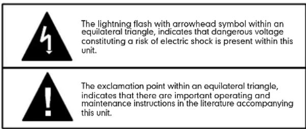
text_image
The lightning flash with arrowhead symbol within an equilateral triangle, indicates that dangerous voltage constituting a risk of electric shock is present within this unit. The exclamation point within an equilateral triangle, indicates that there are important operating and maintenance instructions in the literature accompanying this unit.FOR UNITED KINGDOM:
FOR YOUR SAFETY, PLEASE READ THE FOLLOWING TEXT CAREFULLY
This appliance is supplied with a molded 3-pin mains plug for your safety and convenience.
A 5 amp fuse is fitted in this plug.
Should the fuse need to be replaced, please ensure that the replacement fuse has a rating of 5 amps and that it is approved by ASTA or BSI to BSI1362.
Check for the ASTA mark ◆or the BSI mark ▼ on the body of the fuse.
If the plug contains a removable fuse cover, you must ensure that it is refitted when the fuse is replaced.
If the fuse is lost, the plug must not be used until a replacement cover is obtained.
A replacement fuse cover can be obtained from your local Hammond Dealer.
IF THE FITTED MOULDED PLUG IS UNSUITABLE FOR THE SOCKET OUTLET IN YOUR HOME, THEN THE FUSE SHOULD BE REMOVED AND THE PLUG CUT OFF AND DISPOSED OF SAFELY.
THERE IS A DANGER OF SEVERE ELECTRICAL SHOCK IF THE CUT-OFF PLUG IS INSERTED INTO ANY 13 AMP SOCKET.
If a new plug is to be fitted please observe the wiring code as shown below.
If in any doubt, please consult a qualified electrician.
IMPORTANT - The wires in this mains lead are coloured in accordance with the following code:
Blue: Neutral
Brown: Live
As the colours of the wires in the mains lead of this unit may not correspond with the coloured marking identifying the terminals in your plug, proceed as follows.
The wire which is coloured BLUE must be connected to the terminal in the plug which is marked with the letter N or coloured BLACK.
The wire which is coloured BROWN must be connected to the terminal in the plug which is marked with the letter L or coloured RED.
Under no circumstances should either of these wires be connected to the earth terminal of the three-pin plug, marked with the letter E or the Earth Symbol ± .
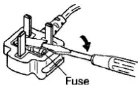
How to replace the fuse. Open the fuse compartment with a screwdriver and replace the fuse and fuse cover.
text_image
Fusethank
you...
for your purchase of the Leslie ^® Speaker System. Your new Leslie Speaker culminates many years of research and dedication to the art of sound reproduction. This new Leslie Speaker has been designed to provide the utmost in musical enchantment, plus dependable service.
The Leslie Speaker system sets revolutionary new standards of organ speaker performance, achieving heights of musical excellence never before considered possible. Not just another speaker - it marks a major breakthrough in organ sound, perhaps the most significant step forward since the introduction of the electronic organ.
Many features have been included in the speaker to insure the finest organ sound possible. Please take a moment to read this manual, then turn on your new Leslie Speaker and enjoy your organ playing to the fullest.
IMPORTANT - PLEASE READ
Your new Leslie Speaker is designed to give you the true and authentic Leslie Sound, as well as provide you great flexibility in how you want to play. This Guide is designed to explain the operating features of your Leslie Speaker as simply and graphically as possible.
This new Leslie has a number of Advanced Features which this Guide will explain in detail. Each feature is treated as an explanation unto itself, and does not require you to already have prior working knowledge of some other feature.
Do not be daunted by the number of steps required to perform each operation. Each step is simple. Simply bear these things in mind:
- Read each step carefully.
- Don't skip any of the steps.
- Don't perform the steps out of sequence.
With these guidelines, you are well on your way to mastering all of the many sounds and features of your Leslie Speaker.
- Table of Contents -
2101/2102/2103 Specifications & Description 2
Making the Connections ....
Connecting to a single-channel Hammond Organ using the 11-pin receptacle .
Connecting to the XE-1/CMS-100/XT-series/XH-series using the 11-pin receptacle .... 4
Connecting using the 8-pin receptacle (XM-1, XB-1)
Connecting using the ROTARY IN jack
Connecting the Leslie 2121 Stationary-Unit 6
ROT BASS LEVEL / HORN LEVEL
Connecting two Stationary-Units for Stereo Separation
Connecting two Horn Units to two Stationary-Units
Leslie Control Center 9,1
Advanced Features 11
A Brief History of the Leslie Speaker ....
Why Leslie Speed Controls?......
Slow Speed 13
Fast Speed 13
Rise Time 14
Fall Time 14
Brake Time 15
Rotor Direction.... 15
Horn Character....16
Crossover Frequency 1
Microphone Angle and Distance ....
Cabinet Resonance 18
MIDI Control Channel 1
MIDI Program Channel 19
MIDI Modulation Wheel Receive......
MIDI Expression Pedal Receive ....
S/F (Slow/Fast) Foot Switch Type....
S/F (Slow/Fast) Foot Switch Control Code ....
MIDI Dump Out 22
P.F.SW Type 23
Presets 24
Default 24
Controlling the Speaker via MIDI 25
Example of Controlling the Advanced Features of the Leslie via MIDI 25
SPECIAL NOTE: Connecting older digital Hammond Organs via MIDI .....
Connecting using the XB-2, XB-5 or A-205......
Connecting the XB-3/XC-3 or XB-3A/XC-3A ....
Preset Parameters 27
System Parameters 27
Parameter Settings 28
MIDI Information 29
MIDI Implementation Chart 30
flowchart
graph TD
    A["2°tweeter"] --> B["treble driver"]
    C["2°tweeter"] --> B
    B --> D["Lch amp 50w"]
    B --> E["horn amp 50w"]
    B --> F["Rch amp 50w"]
    D --> G["DSP crossover network above fc below fc"]
    E --> G
    F --> G
    G --> H["above 125Hz"]
    G --> I["below 125Hz"]
    H --> J["volume controls"]
    I --> J
    J --> K["rotary line in"]
    J --> L["rotary"]
    J --> M["Lch stationary & bass"]
    J --> N["Rch stationary & bass"]
    J --> O["line amp"]
    P["5°speaker"] --> Q["DSP simulator"]
    Q --> R["line amp"]
    Q --> S["line low rotary"]
    Q --> T["L/mono stationary & bass"]
    Q --> U["Rch stationary & bass"]
    Q --> V["L/mono line in"]
    style A fill:#f9f,stroke:#333
    style C fill:#f9f,stroke:#333
    style P fill:#f9f,stroke:#333
    style Q fill:#ccf,stroke:#333
SPECIFICATIONS:
Type:
3-channel (ROTARY, STATIONARY-L, STATIONARY-R)
Animation:
Horn Rotor, Digital Bass Rotor
Power Output:
Rotary Horn 50W. Stationary Channels 50W×2. 150 watts total.
Speakers:
Compression Driver for Horn, 13cm Woofer × 2, 5cm Tweeter × 2.
Controls:
Volume: STA-L, STA-R, ROTARY, OVERDRIVE
8-position Function Selector Touch Buttons: PRESET 1-2, MEMORY
Channel Mode:
NORMAL-STA MONO, STA ROT BASS-MUTE
Display:
7-segment, 2-digit LED display
Terminals:
Leslie 11-pin Receptacle, Leslie 8-pin Receptacle, ROTARY INPUT, LINE OUT (STATIONARY-L, STATIONARY-R, ROTARY-L, ROTARY-R), MIDI IN, MIDI OUT, REMOTE (Remote Power for #2121).
Foot Switch:
Foot Switch 1 (PRESET), Foot Switch 2 (SLOW/FAST/STOP)
Powre Consumption:
AC 120V,220-230V,230-240V 190W.
Dimensions:
51(W)×52(D)×33(H) cm
Weight:
23 kg
Optional Accessories:
Stationary-Unit #2121, Leslie 11-pin Cable, Leslie 8-pin Cable (LC8-7M), Stand Adapter, Foot Switch (FS-9H).
to insure your enjoyment of performing music.
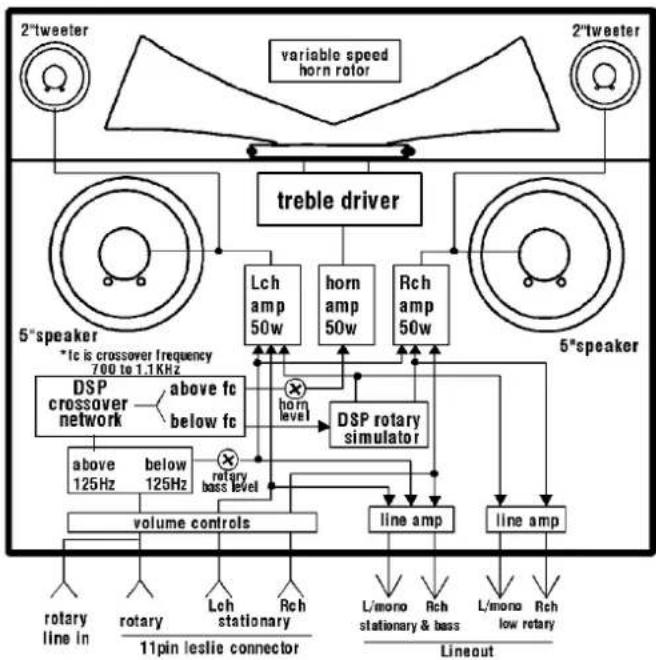
The Leslie ^® models 2101, 2102 and 2103 contain two rotors to produce the world-renowned Leslie Speaker "Sound-In-Motion ^® ." The sound is "separated" with the highs reproduced by a horn rotor and the lows reproduced by a two 5" speakers with electronic rotor capability. Both the mechanical and electronic rotors can be operated in two modes - Fast (Tremolo) or Slow (Chorale).
In addition, there is a stationary channel designed to accommodate the audio signal from another sound source such as a synthesizer or external sound module. This audio signal is handled by three speakers - the two 13cm speakers which also handle the lower frequencies for the rotary channel, and two 5cm dome tweeters for the high frequencies.
The Model 2101 cabinet comes in a textured black finish with side handles for professional portability, the Model 2102 cabinet is finished in silver and the Model 2103 is finished in a rich Walnut.
making the connections
♦ Connecting to a single-channel Hammond Organ using the 11-pin receptacle
flowchart
graph TD
    A["MIDI OUT"] --> B["11-pin Leslie Cable"]
    C["MIDI IN"] --> B
    D["XK-2"] --> E["HAMMOND"]
    E --> F["Antenna with keyboard"]
    F --> G["Antenna with antenna"]
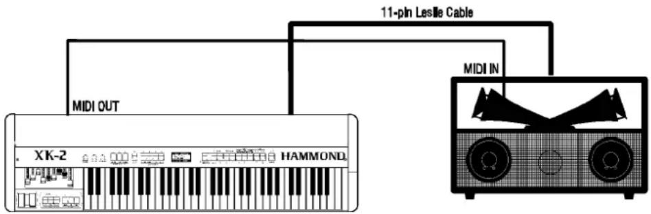
The above example show a Hammond XK-2 connected to a Leslie Horn Unit. The audio signal is connected via an 11-pin Leslie Cable.
To make this hookup:
- Make sure the power to both units is "OFF."
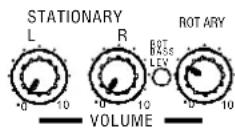
- Set the STATIONARY Volume Controls on the Leslie Speaker to "0" or Off to reduce noise, since the XK-2 uses the Rotary channel only.
- Set the ROTARY Volume Control to a low setting (the 10 o'clock position is recommended) when first making the connection.
- Plug the female end of the Leslie Connector Cable into the receptacle on the back of the Leslie Speaker.
- Plug the male end of the Connector Cable into the 11-pin Leslie socket of the organ.
- Turn the organ “ON.” After about 5 seconds, the Leslie Speaker will turn “ON.” Then adjust the volume settings of both units to your liking.
NOTE: In addition, a MIDI cable can be connected from the MIDI OUT of the XK-2 to the MIDI IN of the Leslie to allow the XK-2 to control the Advanced Features of the Leslie. Please see page 28 for more information.
NOTE: The above hookup will also work with older Hammond products such as XB-2, XB-5 and XB-3; however, all MIDI features may not be available. Please see page 27 for more information.
♦ Connecting to the XE-1/CMS-100/XT-series/XH-series using the 11-pin receptacle
flowchart
graph TD
    A["MIDI OUT"] --> B["11-pin Leslie Cable"]
    B --> C["MIDI IN"]
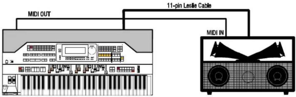
The above example show a Hammond XE-1 connected to a Leslie Horn Unit. The audio signal is connected via an 11-pin Leslie Cable. The above hookup can be used with any current Hammond Organ; however, all MIDI features may not be able to be controlled. Please see page 27 for more information.
To make this hookup:
text_image
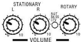
STATIONARY L R ROTARY 0 10 0 10 0 10 VOLUME- Make sure the power to both units is "OFF."
- Set the STATIONARY Volume Controls on the Leslie Speaker to a low setting (the 10 o'clock position is recommended) when first making the connection.
- Set the ROTARY Volume Control to a low setting (the 10 o'clock position is recommended) when first making the connection.
- Plug the female end of the Leslie Connector Cable into the receptacle on the back of the Leslie Speaker.
- Plug the male end of the Connector Cable into the 11-pin Leslie socket of the organ.
- Turn the organ "ON." After about 5 seconds, the Leslie Speaker will turn "ON." Then adjust the volume settings of both units to your liking.
NOTE: In addition, a MIDI cable can be connected from the MIDI OUT of the organ to the MIDI IN of the Leslie to allow the organ to control the Advanced Features of the Leslie.
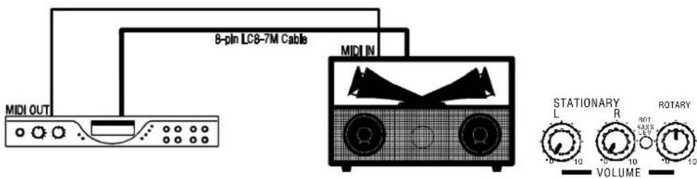
♦ Connecting using the 8-pin receptacle (XM-1, XB-1)
text_image
8-pin LC8-7M Cable MIDI OUT MIDI IN STATIONARY L R ROT 5ARS 10V 10 10 VOLUME 10 10 10The above example shows a Hammond XM-1 connected to a Leslie Horn Unit. The audio signal is connected via the special 8-pin cable. In addition, a MIDI cable can be connected from the MIDI OUT of the XM-1 to the MIDI IN of the Leslie to allow the XM-1 to control the Advanced Features of the Leslie.
NOTE: The Remote Turn-on feature is not available when using the 8-pin interface.
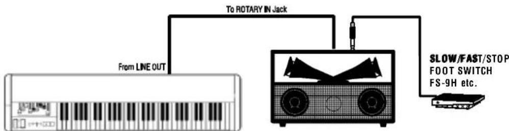
♦ Connecting using the ROTARY IN jack
text_image
To ROTARY IN JACK From LINE OUT SLOW/FAST/STOP FOOT SWITCH FS-9H etc.The above example shows a hookup using the LINE OUT of another instrument. The audio signal is connected via a patch cord from the LINE OUT jack (or the L/MONO jack if there is more than one) to the ROTARY IN jack of the Leslie.
NOTE: You may also use the L/MONO jack of a Hammond instrument in this fashion; however, you will NOT be able to control the rotor speed using the Touch Tabs. Use a Foot Switch for this purpose.
♦ Connecting the Leslie 2121 Stationary-Unit
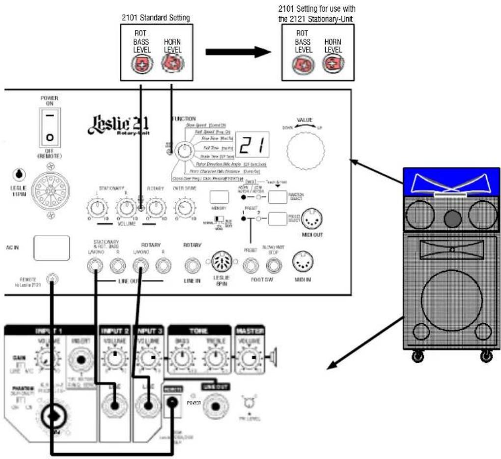
To connect the Leslie 2121 Stationary-Unit to the Horn-Unit, do the following:
-
Make Make the power to avail units, including underlying contracting disting institution "OFF." OFF."
-
Connéou the Stabio Sarty Unit as shown below be Setch Set control on the Stationary Unit-Unit similar to the settings shown below. Sett the ROT BASSS LEVEL and HORN LEVEL trimpots on the Horn-Unit as shown.
text_image
2101 Standard Setting ROT BASS LEVEL HORN LEVEL 2101 Setting for use with the 2121 Stationary-Unit ROT BASS LEVEL HORN LEVEL POWER ON OFF (REMOTE) LESLIE TIPIN AC IN REMOTE TO LESLIE BT21 LESLIE 21 Rotary-Unit FUNCTION Blue Signal Control On Fast Speed, Peak On Fast Time, Peak On Rotor Direction, Mid Angle, Off Current Home Diameter, Mid Distance, Damp On Cross-See Reg. Cable, Analog@STATION DOWN UP VALUE OFF STATIONARY R R ROTARY OVER TIME MEMORY METHI MIXI OUT HIGH / LOW NODA / ROSA FUNCTION SHIFT PRESET MIDI OUT RIGHT SLOW/AST STOP MIDI IN LINE OUT LINE IN LESLIE SPIN FOOTSW MIDI IN INPUT 1 VOLUME INPUT 2 VOLUME INPUT 3 TONE SMASS TRIPLE MASTER VOLUME PHASE OF OUT-ONLY ON ON ON ON POWER CAN OUTNOTE: the two LI-40 audio cables and the DCC-2 power connecting cable are supplied with the 2121 Stationary-Unit.
-
Turn Further cotheo-coccienging-in-mentBoth Castle Leslie will be epidwerped up automatically.
-
Finally, then MASTERSVDRUMEURMEryRGomryCloofthe all 15et the letter (12 o'clock) position to check the sound level, then adjust the sound to your liking.
ROT BASS LEVEL / HORN LEVEL
These two Trim Pots can be adjusted using a small screwdriver.

= Minimum setting.

= Maximum setting.

= Center position.
It is recommended that you set these Trim Pots as shown when first making the connections, then adjust them later to your preference.
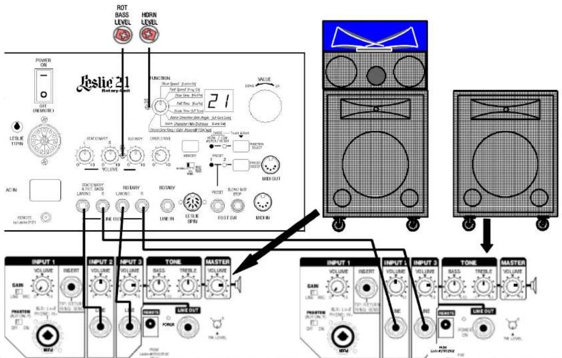
♦ Connecting two Stationary-Units for Stereo Separation
flowchart
graph TD
    A["Input 1: VOLUME, INSERT, GAIN, POWER OUT"] --> B["INPUT 2: VOLUME, INSERT, LINE OUT"]
    B --> C["INPUT 3: VOLUME, TONE, MASTER, POWER OUT"]
    C --> D["INPUT 4: VOLUME, INSERT, LINE OUT"]
    D --> E["INPUT 5: VOLUME, MASTER, POWER OUT"]
    E --> F["Output: VOLUME, INSERT, LINE OUT"]
The above hookup is recommended when using two 2121 Stationary-Units with a single Horn-Unit. Connecting the LEFT outputs to one Stationary-Unit and the RIGHT outputs to the other Stationary-Unit will provide Stereo separation, particularly to enhance the Bass Rotor effect. Be sure to set the ROT BASS LEVEL and HORN/ LEVEL triimpacts, showing musing as small screwdriver.
NOTE: It is recommended that you set the Volume Controls as shown when first making the connections, then adjust them later to your preference.
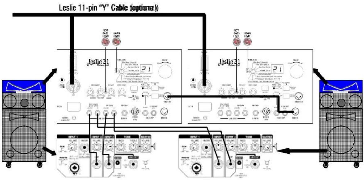
♦ Connecting two Horn-Units to two Stationary-Units
flowchart
graph TD
    A["Input 1: 20V/Hz"] --> B["NOT BASS LIFTS"]
    A --> C["NOW LIFTS"]
    D["Input 2: 20V/Hz"] --> E["ROT BASS LIFTS"]
    D --> F["NOW LIFTS"]
    G["Input 3: 20V/Hz"] --> H["ROT BASS LIFTS"]
    G --> I["NOW LIFTS"]
    J["Input 4: 20V/Hz"] --> K["NOW LIFTS"]
    L["Input 5: 20V/Hz"] --> M["NOW LIFTS"]
    N["Input 6: 20V/Hz"] --> O["NOW LIFTS"]
    P["Input 7: 20V/Hz"] --> Q["NOW LIFTS"]
    R["Input 8: 20V/Hz"] --> S["NOW LIFTS"]
    T["Input 9: 20V/Hz"] --> U["NOW LIFTS"]
    V["Input 10: 20V/Hz"] --> W["NOW LIFTS"]
    X["Input 11: 20V/Hz"] --> Y["NOW LIFTS"]
    Z["Input 12: 20V/Hz"] --> AA["NOW LIFTS"]
    AB["Input 13: 20V/Hz"] --> AC["NOW LIFTS"]
    AD["Input 14: 20V/Hz"] --> AE["NOW LIFTS"]
    AF["Input 15: 20V/Hz"] --> AG["NOW LIFTS"]
    AH["Input 16: 20V/Hz"] --> AI["NOW LIFTS"]
    AJ["Input 17: 20V/Hz"] --> AK["NOW LIFTS"]
    AL["Input 18: 20V/Hz"] --> AM["NOW LIFTS"]
    AN["Input 19: 20V/Hz"] --> AO["NOW LIFTS"]
    AP["Input 20: 20V/Hz"] --> AQ["NOW LIFTS"]
    AR["Input 21: 20V/Hz"] --> AS["NOW LIFTS"]
    AT["Input 22: 20V/Hz"] --> AU["NOW LIFTS"]
    AV["Input 23: 20V/Hz"] --> AW["NOW LIFTS"]
    AX["Input 24: 20V/Hz"] --> AY["NOW LIFTS"]
    AZ["Input 25: 20V/Hz"] --> BA["NOW LIFTS"]
    BB["Input 26: 20V/Hz"] --> BC["NOW LIFTS"]
    BD["Input 27: 20V/Hz"] --> BE["NOW LIFTS"]
    BF["Input 28: 20V/Hz"] --> BG["NOW LIFTS"]
    BH["Input 29: 20V/Hz"] --> BI["NOW LIFTS"]
    BJ["Input 30: 20V/Hz"] --> BK["NOW LIFTS"]
    BL["Input 31: 20V/Hz"] --> BLN["NOW LIFTS"]
Use the above hookup when connecting multiple Leslie 21 Systems. By connecting the two Horn-Units via MIDI, the entire system can be controlled from one master unit. Be sure to set the ROT BASS LEVEL and HORN LEVEL trim pots as shown using a small screwdriver.
NOTE: It is recommended that you set the Volume Controls as shown when first making the connections, then adjust them later to your preference.
controls that enhance the organ sounds
text_image
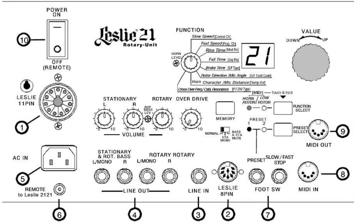
POWER ON OFF (REMOTE) LESLIE 21 Rotary-Unit 10 5 AC IN REMOTE to Leslie 2121 6 4 3 2 7 FUNCTION Slow Speed [Control Ch] Fast Speed [Prog. Ch] Rise Time [Mod Rx] Fall Time [Exp Rx] Brake Time [S/F Type] Rotor Direction /Mic Angle [S/F Cort Code] Horn Character /Mic Distance [Dump Out] Cross Over Freq/ Cable Resonance [P.F.SW Type] VALUE DOWN UP STATIONARY L R ROT BASS LEV VOLUME OVER DRIVE MEMORY NORMAL STA MONO BASS & STA MUTE MIDIOUT 9 PRESET 1 2 FUNCTION SELECT PRESET SELECT MIDI OUT STATIONARY & ROT. BASS L/MONO R ROTARY ROTARY L/MONO R LINE OUT LINE IN LESLIE 8PIN SLOW/FAST STOP FOOT SW MIDI INThe Leslie Control Center is located on the back panel of the Leslie Speaker.
1 - 11-pin Receptacle - This allows direct connection between the Leslie Speaker and the Hammond XB-Series Organs, using the cable supplied with the speaker.
2 - 8-pin DIN Receptacle - This allows direct connection between the Leslie Speaker and the Hammond XB-1 and XM-1 instruments using the special cable provided for this connection.
3 - ROTARY LINE IN - This allows other instruments to connect to the Rotary channel using standard phone cables.
4 - LINE OUT:
STATIONARY & BASS (L/MONO, R) Jacks - These allow both the STATIONARY and the LOW ROTARY channels to be connected to an external amplifier. To connect the STATIONARY UNIT #2121, connect the L/MONO OUT to INPUT 2. ROTARY (L/MONO, R) - This allows the LOW ROTARY channel to be connected to an external amplifier. To connect the STATIONARY UNIT #2121, connect the L/MONO OUT to INPUT 3.
NOTE: The HORN ROTOR channel has no LINE OUT connection due to the acoustic nature of the sound produced. Using the HORN ROTORY channel with external amplification requires a microphone.
5 - AC Power Cord Receptacle - Plug the female end of a grounded AC power cord into this receptacle, and the male end into an AC outlet.
6 - REMOTE - When the Leslie 2121 Stationary-Unit is connected, connect to the REMOTE IN with a DCC-2 cable. The power for the Stationary-Unit can be turned "ON" and "OFF" by the power switch of the Horn-Unit.
NOTE: The REMOTE feature is powered by a battery. The battery's estimated life is approximately 1000 "turn-ons," depending on constancy of electrical current, etc. Do not attempt to replace this battery. Refer all servicing to qualified service personnel.
7 - FOOT SW -
PRESET - Allows you to switch between PRESET 1 and 2 using a latching-type Foot Switch. SLOW/FAST/STOP - Allows you to control the Leslie rotors using the FS-9H Foot Switch. Each time the Foot Switch is activated, the rotors will switch between SLOW and FAST. If the Foot Switch is pressed and held for 1 second, the Rotors will Stop.
8 - MIDI IN - Connects to the MIDI OUT of an organ or keyboard.
9 - MIDI OUT - Connects to the MIDI IN of an additional Leslie Horn-Unit when 2 units are connected in series. The MIDI IN from the organ and the FOOT SW signal of the Horn-Unit are merged in the MIDI OUT.
10 - Power Switch ON / OFF - This allows the Leslie Speaker to be turned "ON" or "OFF."
Continued on next page.
text_image
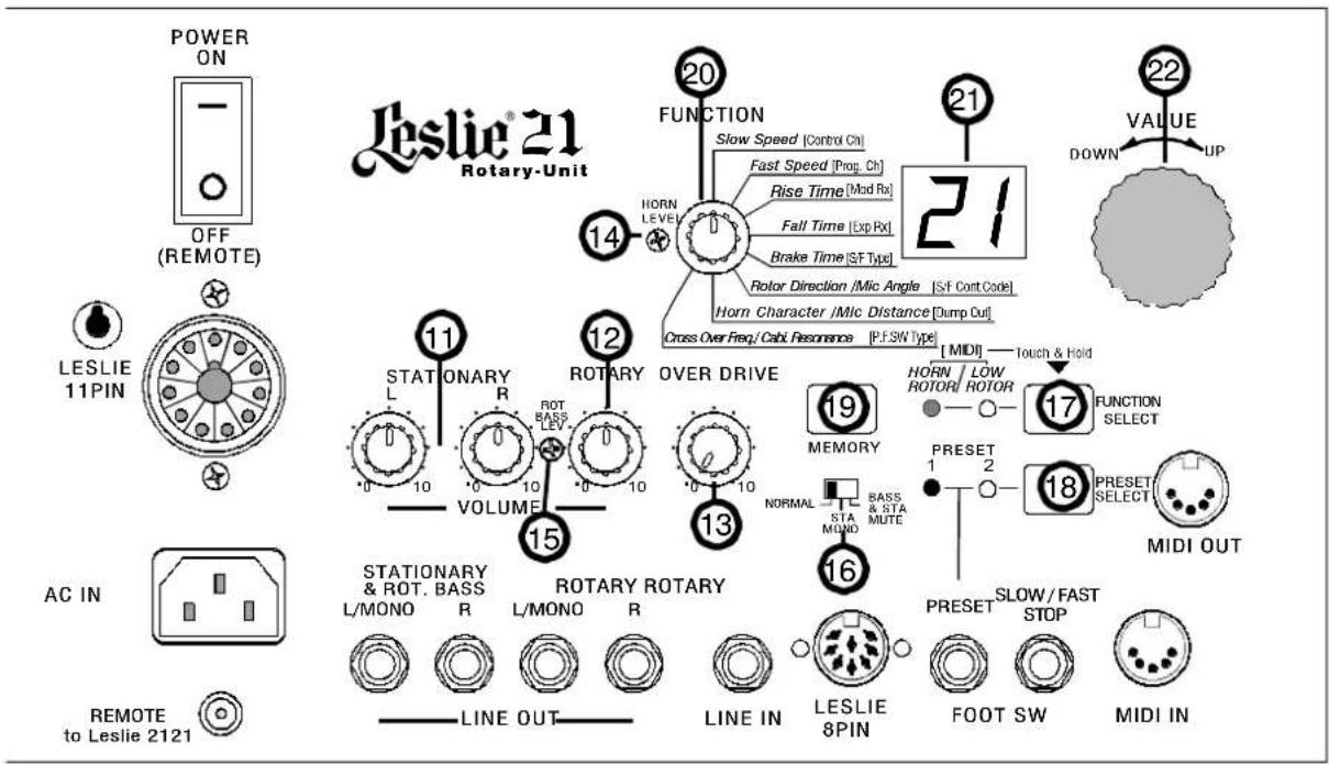
POWER ON OFF (REMOTE) LESLIE® 21 Rotary-Unit 14 FUNCTION Slow Speed [Control On] HORN LEVEL Fast Speed [Prop. Ch] Rise Time [Mod Rx] Fall Time [Exp Rx] Brake Time [SF Type] 20 21 22 DOWN UP VALUE STATIONARY R ROTARY OVER DRIVE [ MIDI ] HORN / LOW ROTOR/ ROTOR 17 FUNCTION SELECT PRESET 1 2 18 PRESET SELECT MIDI OUT STATIONARY & ROT. BASS L/MONO R ROTARY ROTARY L/MONO R LINE IN LESLIE 8PIN SLOW/FAST STOP FOOT SW MIDI IN AC IN REMOTE to Leslie 212111 - STATIONARY VOLUME CONTROLS
L - Allows you to adjust the Volume of the Stationary Left channel.
R - Allows you to adjust the Volume of the Stationary Right channel.
12 - ROTARY - Use this trim pot to adjust the volume of the Rotary channel.
13 - OVERDRIVE - This allows you to adjust the Overdrive Level of the Rotary channel.
14 - HORN LEVEL - Use this trim pot to adjust the Horn Rotor level when the Stationary Unit 2121 or an exterior amplifier is connected.
15 - ROT BASS LEVEL - Use this trim pot to adjust the Low Rotor (below 125Hz) level when the Stationary Unit 2121 or an exterior amplifier is connected.
16 - CHANNEL SWITCH - Use this switch to control the audio for different Leslie connections.
NORMAL - This is the preferred position for most applications.
STA MONO - Use this position to merge the Stationary Left and Right channels.
BASS & STA MUTE - Silences the Low Rotor and Stationary channels. This position may be desirable if the 2121 Bass unit is used to avoid overdriving the Stationary speakers in the Horn-Unit.
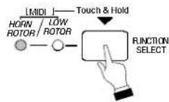
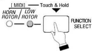
17 - FUNCTION SELECT Touch Button - Allows you to select either Horn Rotor or Low Rotor Advanced Features. Touching and Holding this Touch Button for 1 second will cause both LED's to light and and the MIDI Advanced Features to be accessed.
18 - PRESET SELECT Touch Button - Allows you to select either PRESET 1 or PRESET 2.
19 - MEMORY Touch Button - Allows you to save Presets and to return the Leslie Speaker to its factory default settings.
20 - FUNCTION SWITCH - Allows you to select the values for the Advanced Features, which are explained starting on page 2.
21 - LED DISPLAY - This is a 2-character 7-segment display which allows you to see the values for the selected parameters.
22 - VALUE ADJUST - This Rotary Knob allows you to select the values for the parameters you want to adjust (Slow, Speed, Fast Speed, etc.). The LED Display will change as you adjust the selected Value.
using the advanced features
Your Leslie Speaker has a number of Advanced Features which allow you a great deal of control over the sound and performance you desire. To see the Default Setting for each of these Advanced Features, please consult page 27 of this Guide.
The Leslie Advanced Features allow you to make the following changes to the organ:
- Horn Rotor - Allows you to adjust the Slow and Fast RPMs (Revolutions Per Minute) and the Rise and Fall Time as well as the Brake Time of the Horn Rotor (see pages 13, 14, 15, 14 and 16).
- Low Rotor - Allows you to adjust the Slow and Fast RPMs (Revolutions Per Minute) and the Rise and Fall Time as well as the Brake Time of the Low or Bass Rotor (see pages 13, 14, 15, 14 and 16).
- Microphone Settings - Allows you to adjust the Angle and Distance parameters to simulate different microphone placements (see pages 17).
- Rotor Direction - Allows you to select the direction in which the Horn Rotor will turn. (see page 15).
- Horn Character - Allows you to select the Resonance for the Horn Rotor (see page 16).
- Crossover Freq. - Allows you to select the crossover frequency for the Horn Rotor and the Low Rotor (see page 16).
- Cabinet Resonance - Allows you to simulate the resonance of a Leslie Model 122 Speaker cabinet (see page18).
- Control Ch. - Allows you to select the MIDI Control Channel as well as turn the MIDI Control Channel "ON" and "OFF" (see page 19).
- Prog. Ch. - Allows you to select the MIDI Program Channel as well as turn the MIDI Program Channel “ON” and “OFF” (see page 19).
- Mod Rx - Allows you to use a Modulation Wheel to send Motor Control data (see page 20).
- Exp Rx - Allows you to use an Expression Pedal to send Motor Control data (see page 20).
- S/F Type - Allows you to set up the Latch/Unlatch mode for a Slow/Fast Foot Switch (see page 21).
- S/F Cont. Code - Allows you to select the Control Code for a Slow/Fast Foot Switch (see page 21).
- Dump Out - Allows you to send MIDI Data out via a Data Dump (see page 22).
- P.F.SW Type - Allows you to set up the mode for the Preset Foot Switch (see page 23).
The following pages give a more detailed explanation of how these Advanced Features work.
♦ A Brief History of the Leslie Speaker
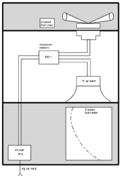
The Leslie Speaker was first developed in the late 1930's by Donald J. Leslie as a way to improve the sound of then-current I Hammond Organs. Mr. Leslie found that rotating a baffle in front of a stationary speaker added a very pleasing “tremolo-type” sound to organ music. This technique is a musical application of the “Doppler effect,” which is the apparent variation in pitch that a stationary listener hears from a moving sound source. The loudness of the sound also appears to vary, and it is this combination of frequency (vibrato) and amplitude (tremolo) modulation that give Leslie Speakers their characteristic sound.
In the majority of Leslie Speakers, there are actually two rotating baffles and two speakers. One speaker handles the high frequencies and is mounted in the upper part of the cabinet. The baffle and motor for this speaker are collectively called the Horn Rotor. The other larger speaker reproduces the bass or pedal frequencies and uses a larger baffle, and is therefore called the Bass or Low Rotor.
flowchart
graph TD
    A["2-speed from rotor"] --> B["crossover network"]
    B --> C["800-"]
    C --> D["15" sp. rotor"]
    D --> E["40 watt amp"]
    E --> F["sg rail nout"]
    G["2-speed foam rotor"] -.-> E
In addition to rotating a baffle at a high rate of speed to produce Tremolo, it is also possible to create a pleasing “Chorale” or “celeste” effect by rotating the baffle at a slow rate of speed - hence the rotor speed designations of Fast and Slow. The Chorale or effect is similar the effect produced by two ranks of pipes being slightly out of tune with each other and being played simultaneously on a pipe organ.
♦ Why Leslie Speed Controls?
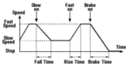
For many years, Leslie Speakers only had one speed - Fast or Tremolo. Even after the Chorale speed was introduced in the mid '60's. variations in the basic speed were introduced by relocating the motor drive belt to a different pulley to make the baffles turn either faster or slower. Although each Leslie Speaker cabinet was and is carefully calibrated at the factory, several factors such as motor age and placement of the belts on the pulleys can affect the speeds of the rotors as well as the time required for the rotors to speed up (Rise Time), slow down (Fall Time) or come to a complete stop (Brake Time).
line
| Time | Speed | | ------------- | ----- | | Fall Time | 0 | | Rise Time | 0 | | Brake Time | 0 |Your new Leslie Speaker features a new brushless DC-controlled motor for the Horn and a newly-designed digital Low rotor which allows control of these parameters to an unprecedented degree. You can now “customize” your Leslie Speaker to produce exactly the characteristics you want.
♦ Slow Speed
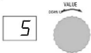
This Advanced Feature allows you to select the Slow Speed Setting that you prefer for either the Horn or the Low Rotor. You can select from “0,” (rotor stopped) through “99” for the Horn and from “01” through “9” for the Low Rotor.
TRY THIS:
- Touch the FUNCTION SELECT switch to select either HORN or LOW ROTOR. The LED (red for Horn, green for Low) will light.
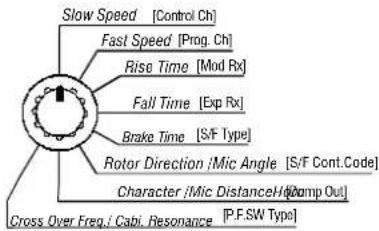
- Select Slow ____ Speed using the Function Selector.
text_image
Slow Speed [Control Ch] Fast Speed [Prog. Ch] Rise Time [Mod Rx] Fall Time [Exp Rx] Brake Time [S/F Type] Rotor Direction /Mic Angle [S/F Cont.Code] Character /Mic Distance/Ho [Comp Out] Cross Over Freq./Cabi. Resonance [P.F.SW Type]- Use the VALUE Rotary Knob to select the value you want. Make sure the Leslie is set at Slow Speed so that you can hear the effect when you make changes.
text_image
5 VALUE DOWN UP♦ Fast Speed
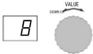
This Advanced Feature allows you to select the Fast Speed Setting that you prefer for either the Horn or Low Rotor. You can select from "0," or stop, through "21" for both Horn and Low Rotors.
TRY THIS:
- Touch the FUNCTION SELECT switch to select either HORN or LOW ROTOR. The LED (red for Horn, green for Low) will light.
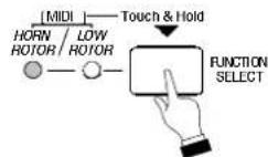
- Select Fast ____ Speed using the Function Selector.
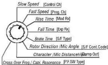
text_image
Slow Speed [Control Ch] Fast Speed [Prog. Ch] Rise Time [Mod Rx] Fall Time [Exp Rx] Brake Time [S/F Type] Rotor Direction /Mic Angle [S/F Cont.Code] Character /Mic Distance/Ho [Omp Out] Cross Over Freq./Capi. Resonance [P.F.SW Type]- Use the VALUE Rotary Knob to select the value you want. Make sure the Leslie is set at Fast Speed so that you can hear the effect when you make changes.
text_image
8 VALUE DOWN UPThe above data can be stored to a Preset. Please see page 24 for information on how to save Presets.
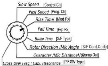
♦ Rise Time
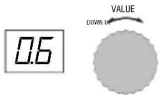
This Advanced Feature allows you to select the time required for the Rotors to go from Slow to Fast. You can select from "0.2" seconds through "12" seconds.
TRY THIS:
-
Touch the FUNCTION SELECT switch to select either HORN or LOW ROTOR. The LED (red for Horn, green for Low) will light.
-
Select Rise ____ Time using the Function Selector.
text_image
Slow Speed [Control Ch] Fast Speed [Prog. Ch] Rise Time [Mod Rx] Fall Time [Exp Rx] Brake Time [S/F Type] Rotor Direction /Mic Angle [S/F Cont.Code] Character /Mic Distance/Ho Jump Out Cross Over Freq./Cabi. Resonance [P.F.SW Type]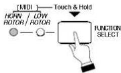
- Use the VALUE Rotary Knob to select the value you want.
text_image
0.6 VALUE DOWN OF◆ Fall Time
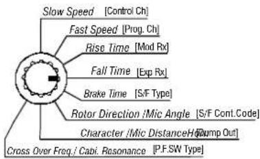
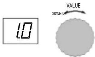
This Advanced Feature allows you select the time required for the Rotors to go from Fast to Slow. You can select from "0.2" seconds through "12" seconds. The default setting is "1.0" seconds for the Horn Rotor and "8.0" seconds for the Low Rotor.
TRY THIS:
-
Touch the FUNCTION SELECT switch to select either HORN or LOW ROTOR. The LED (red for Horn, green for Low) will light.
-
Select Fall ____ Time using the Function Selector.
text_image
Slow Speed [Control Ch] Fast Speed [Prog. Ch] Rise Time [Mod Rx] Fall Time [Exp Rx] Brake Time [S/F Type] Rotor Direction /Mic Angle [S/F Cont.Code] Character /Mic Distance/Ho [Jump Out] Cross Over Freq./Capi. Resonance [P.F.SW Type]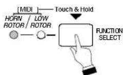
- Use the VALUE Rotary Knob to select the value you want.
text_image
1.0 VALUE DOWN UPThe above data can be stored to a Preset. Please see page 24 for information on how to save Presets.
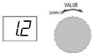
♦ Brake Time
This Advanced Feature allows you to select the time required for the rotors to come to a complete stop from Fast mode. You can select from "0.2" seconds through "12" seconds.
TRY THIS:
-
Touch the FUNCTION SELECT switch to select either HORN or LOW ROTOR. The LED (red for Horn, green for Low) will light.
-
Select Brake Time using the Function Selector.
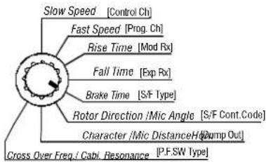
text_image
Slow Speed [Control Ch] Fast Speed [Prog. Ch] Rise Time [Mod Rx] Fall Time [Exp Rx] Brake Time [S/F Type] Rotor Direction /Mic Angle [S/F Cont.Code] Character /Mic Distance/Ho Jump Out Cross Over Freq./Cabi. Resonance [P.F.SW Type]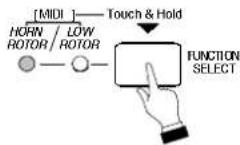
- Use the VALUE Rotary Knob to select the value you want.
text_image
1.2 VALUE DOWN UP♦ Rotor Direction
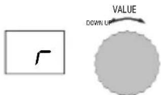
This Advanced Feature allows you to select the direction in which the Horn Rotor will turn. You can select either "r" (right, or clockwise) or "L" (left or counter-clockwise). The default setting is "r."
TRY THIS:
-
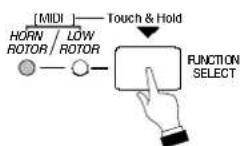
Touch the FUNCTION SELECT switch to select HORN ROTOR. The red LED will light.
-
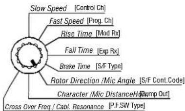
Select Rotor ____ Direction / Mic Angle using the Function Selector.
text_image
Slow Speed [Control Ch] Fast Speed [Prog. Ch] Rise Time [Mod Rx] Fall Time [Exp Rx] Brake Time [S/F Type] Rotor Direction /Mic Angle [S/F Cont.Code] Character /Mic Distance/Ho [Jump Out] Cross Over Freq./Cabi. Resonance [P.F.SW Type]- Use the VALUE Rotary Knob to select the value you want.
text_image
r VALUE DOWN UPThe above data can be stored to a Preset. Please see page 24 for information on how to save Presets.
♦ Horn Character
This Advanced Feature allows you to select the Resonance frequency for the Horn Rotor. You can select "1.0" (1.0kHz), "1.5" (1.5kHz), "2.0" (2.0kHz) or "Fl" (flat).
TRY THIS:
- Touch the FUNCTION SELECT switch to select HORN ROTOR. The red LED will light.
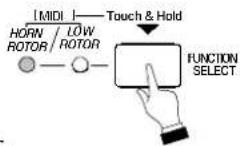
- Select Horn ____ Character / Mic Distance using the Function Selector.
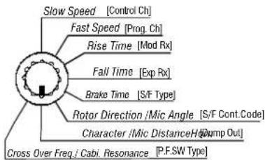
text_image
Slow Speed [Control Ch] Fast Speed [Prog. Ch] Rise Time [Mod Rx] Fall Time [Exp Rx] Brake Time [S/F Type] Rotor Direction /Mic Angle [S/F Cont.Code] Character /Mic Distance/Ho Jump Out Cross Over Freq./Cabi. Resonance [P.F.SW Type]- Use the VALUE Rotary Knob to select the value you want.
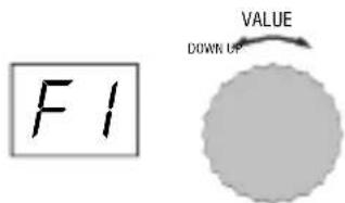
text_image
F1 VALUE DOWN UP♦ Crossover Frequency
This Advanced Feature allows you to select the crossover frequency for the Horn and Low Rotor. You can select "0.7" (700Hz), "0.8" (800Hz) or "1.0" (1.0kHz).
TRY THIS:
- Touch the FUNCTION SELECT switch to select HORN ROTOR. The red LED will light.
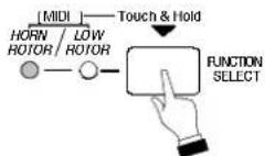
- Select Cross ____ Over Freq. using the Function Selector.
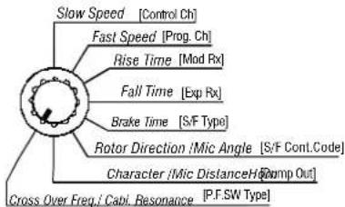
text_image
Slow Speed [Control Ch] Fast Speed [Prog. Ch] Rise Time [Mod Rx] Fall Time [Exp Rx] Brake Time [S/F Type] Rotor Direction /Mic Angle [S/F Cont.Code] Character /Mic Distance/H [Romp Out] Cross Over Freq./Capi. Resonance [P.F.SW Type]- Use the VALUE Rotary Knob to select the value you want.
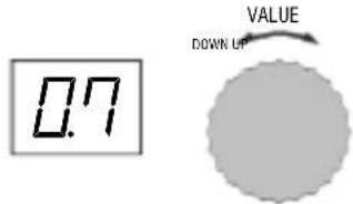
text_image
0.7 VALUE DOWN UPThe above data can be stored to a Preset. Please see page 24 for information on how to save Presets.
♦ Microphone Angle and Distance
When a Leslie Speaker cabinet or cabinets are used in a large facility such as an auditorium or outdoor arena, the Leslie(s) are frequently “miked” to insure that the sound carries adequately. Sound technicians have discovered that the placement of the microphones greatly affects the character of the sound heard by the audience from the Leslie Speaker(s) (see the diagram below).
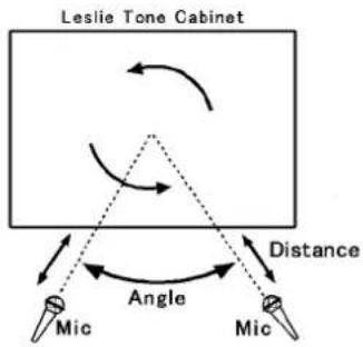
text_image
Leslie Tone Cabinet Distance Angle Mic MicThis Advanced Feature allows you to simulate various microphone distances and angles facing the Low Rotor.
TRY THIS:
-
Touch the FUNCTION SELECT switch to select LOW ROTOR. The green LED will light.
-
Select Mic ____ Angle or Mic Distance using the Function Selector.
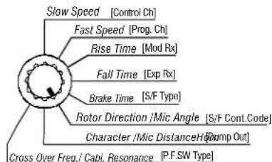
text_image
Slow Speed [Control Ch] Fast Speed [Prog. Ch] Rise Time [Mod Rx] Fall Time [Exp Rx] Brake Time [S/F Type] Rotor Direction /Mic Angle [S/F Cont.Code] Character /Mic Distance/Ho [Comp Out] Cross Over Freq./Capi. Resonance [P.F.SW Type]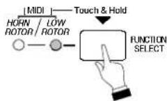
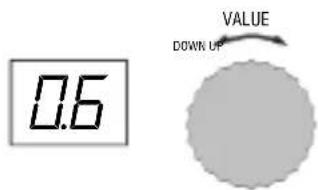
- Use the VALUE Rotary Knob to select the value you want.
text_image
0.6 VALUE DOWN UPThe data chart below shows the options that you may select.
| MICROPHONE SETTINGS | |
| Option | Parameter Limits |
| Angle | 0 ~ 180° |
| Distance | 0.3m ~ 2.7m |
NOTE: Both these are subtle effects and may require careful listening to detect the differences among the various settings.
The above data can be stored to a Preset. Please see page 24 for information on how to save Presets.
♦ Cabinet Resonance
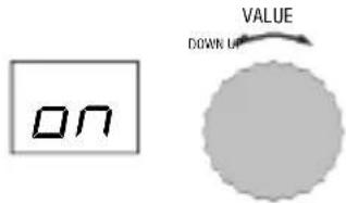
This Advanced Feature allows you to simulate the resonance of a Leslie Model 122 Speaker cabinet. You can turn this feature "ON" or "OFF."
TRY THIS:
- Touch the FUNCTION SELECT switch to select LOW ROTOR. The green LED will light.
flowchart
graph TD
    A["Input: Horn/ROTOR"] --> B{MIDI}
    B --> C["Low/ROTOR"]
    C --> D["Touch & Hold"]
    D --> E["FUNCTION SELECT"]
- Select Cab. _Res. using the Function Selector.
text_image
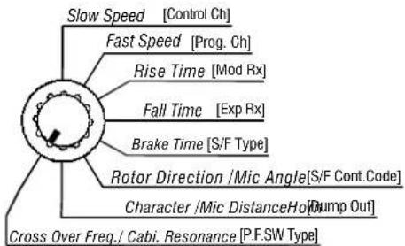
Slow Speed [Control Ch] Fast Speed [Prog. Ch] Rise Time [Mod Rx] Fall Time [Exp Rx] Brake Time [S/F Type] Rotor Direction /Mic Angle[S/F Cont.Code] Character /Mic DistanceHolt [Jump Out] Cross Over Freq./ Cabi. Resonance [P.F.SW Type]- Use the VALUE Rotary Knob to select the value you want.
text_image
ON VALUE DOWN UThe above data can be stored to a Preset. Please see page 24 for information on how to save Presets.
♦ MIDI Control Channel
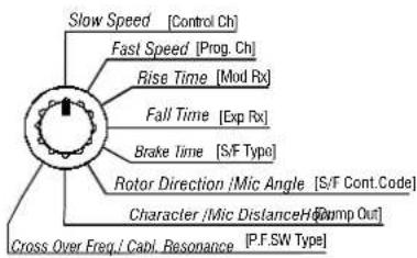
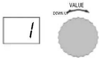
This Advanced Feature allows the Leslie to receive MIDI Controller information. You can select MIDI Channels "1" through "16" as well as "OFF."
TRY THIS:
-
Touch and Hold the FUNCTION SELECT switch for approximately 1 second. Both LEDs will light.
-
Select Control Ch using the Function Selector.
text_image
Slow Speed [Control Ch] Fast Speed [Prog. Ch] Rise Time [Mod Rx] Fall Time [Exp Rx] Brake Time [S/F Type] Rotor Direction /Mic Angle [S/F Cont.Code] Character /Mic DistanceH [Stmp Out] Cross Over Freq./Capi. Resonance [P.F.SW Type]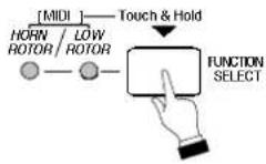
- Use the VALUE Rotary Knob to select the value you want.
text_image
VALUE DOWN UP♦ MIDI Program Channel
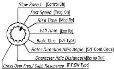
This Advanced Feature allows the Leslie Speaker to receive MIDI Program information in order to change Presets. You can select from MIDI Program Number Channels “1” through “16.” as well as “OFF.”
TRY THIS:
-
Touch and Hold the FUNCTION SELECT switch for approximately 1 second. Both LEDs will light.
-
Select Program Ch using the Function Selector.
text_image
Slow Speed [Control Ch] Fast Speed [Prog. Ch] Rise Time [Mod Rx] Fall Time [Exp Rx] Brake Time [S/F Type] Rotor Direction /Mic Angle [S/F Cont.Code] Character /Mic Distance/Ho[comp Out] Cross Over Freq./Capi. Resonance [P.F.SW Type]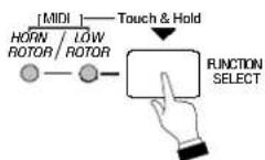
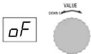
- Use the VALUE Rotary Knob to select the value you want.
text_image
OF VALUE DOWN UPNOTE: Sending Program # 1 will select Preset 1, while sending Program # 2 will select Preset 2. For more information about Presets, please see page 23.
♦ MIDI Modulation Wheel Receive
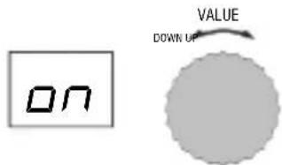
This Advanced Feature allows you to use a Modulation Wheel to continuously vary the Rotor Speed of the Leslie Speaker. You can turn this feature "ON" or "OFF."
TRY THIS:
-
Touch and Hold the FUNCTION SELECT switch for approximately 1 second. Both LEDs will light.
-
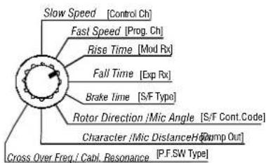
Select Mod ____ Rx using the Function Selector.
text_image
Slow Speed [Control Ch] Fast Speed [Prog. Ch] Rise Time [Mod Rx] Fall Time [Exp Rx] Brake Time [S/F Type] Rotor Direction /Mic Angle [S/F Cont.Code] Character /Mic Distance/Ho[Omp Out] Cross Over Freq./Capi. Resonance [P.F.SW Type]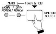
- Use the VALUE Rotary Knob to select the value you want.
text_image
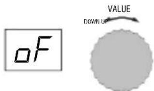
ON VALUE DOWN UP♦ MIDI Expression Pedal Receive
This Advanced Feature allows you to use an Expression Pedal to continuously vary the Rotor Speed of the Leslie Speaker. You can turn this feature "ON" or "OFF."
TRY THIS:
-
Touch and Hold the FUNCTION SELECT switch for approximately 1 second. Both LEDs will light.
-
Select Slow ____ Speed using the Function Selector.
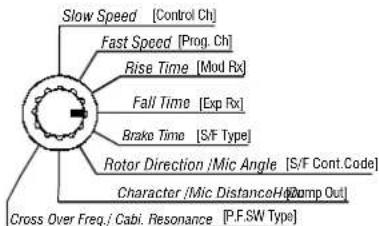
text_image
Slow Speed [Control Ch] Fast Speed [Prog. Ch] Rise Time [Mod Rx] Fall Time [Exp Rx] Brake Time [S/F Type] Rotor Direction /Mic Angle [S/F Cont.Code] Character /Mic DistanceH [Gamp Out] Cross Over Freq./Cabi. Resonance [P.F.SW Type]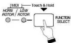
- Use the VALUE Rotary Knob to select the value you want.
text_image
OF VALUE DOWN UP♦ S/F (Slow/Fast) Foot Switch Type
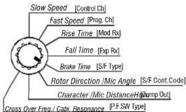
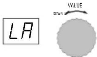
This Advanced Feature allows you to set up the mode for the Slow/Fast Foot Switch. You can select "LA" (Latch, or alternate press-on-press-off mode) or "uL" (Unlatch, or momentary press-on-release-off) mode.
TRY THIS:
-
Touch and Hold the FUNCTION SELECT switch for approximately 1 second. Both LEDs will light.
-
Select S/F ____ Cont. Code using the Function Selector.
text_image
Slow Speed [Control Ch] Fast Speed [Prog. Ch] Rise Time [Mod Rx] Fall Time [Exp Rx] Brake Time [S/F Type] Rotor Direction /Mic Angle [S/F Cont.Code] Character /Mic Distance/Ho [Jump Out] Cross Over Freq./Cabi. Resonance [P.F.SW Type]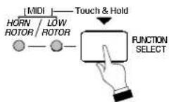
- Use the VALUE Rotary Knob to select the value you want.
text_image
LA VALUE DOWN OF♦ S/F (Slow/Fast) Foot Switch Control Code
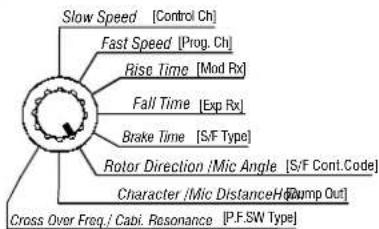
This Advanced Feature allows you to select the Control Code for a Slow/Fast Foot Switch. You can select from "0" through "99."
TRY THIS:
-
Touch and Hold the FUNCTION SELECT switch for approximately 1 second. Both LEDs will light.
-
Select S/F ____ Cont. Code using the Function Selector.
text_image
Slow Speed [Control Ch] Fast Speed [Prog. Ch] Rise Time [Mod Rx] Fall Time [Exp Rx] Brake Time [S/F Type] Rotor Direction /Mic Angle [S/F Cont.Code] Character /Mic Distance/Ho [Jump Out] Cross Over Freq./Cabi. Resonance [P.F.SW Type]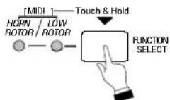
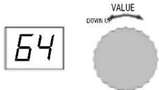
- Use the VALUE Rotary Knob to select the value you want.
text_image
64 VALUE DOWN UP♦ MIDI Dump Out
This Advanced Feature allows you to send MIDI Data out via a Data Dump.
NOTE: The feature is helpful if you want to dump Preset Data out to a MIDI data recorder for later use.
TRY THIS:
-
Prepare your MIDI Data recorder to Receive a MIDI Dump.
-
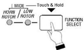
Touch and Hold the FUNCTION SELECT switch for approximately 1 second. Both LEDs will light.
flowchart
graph TD
    A["FUNCTION SELECT"] --> B["MIDI"]
    B --> C["HORN/LOW/ROTOR"]
    C --> D["Touch & Hold"]
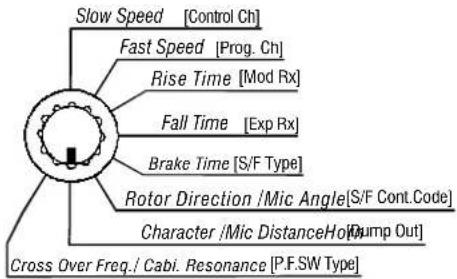
- Select Dump Out using the Function Selector.
text_image
Slow Speed [Control Ch] Fast Speed [Prog. Ch] Rise Time [Mod Rx] Fall Time [Exp Rx] Brake Time [S/F Type] Rotor Direction /Mic Angle[S/F Cont.Code] Character /Mic DistanceHolt [Jump Out] Cross Over Freq./ Cabi. Resonance [P.F.SW Type]-
Start the MIDI Data recorder.
-
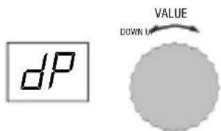
Turn the VALUE Rotary Knob until the display starts flashing. The Data Transfer will then commence.
text_image
dP VALUE DOWN UPWhen the display stops flashing, the Data Dump is complete.
♦ MIDI Dump IN
No special setup is required to send a MIDI Data Dump from another MIDI device to the Leslie. Simply connect the other MIDI device to the Leslie and transmit the data.
♦ P.F.SW Type
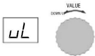
This Advanced Feature allows you to set up the mode for the Preset Foot Switch. You can select "La" (Latch, or alternate press-on-press-off mode) or "uL" (Unlatch, or momentary press-on-release-off) mode.
TRY THIS:
- Touch and Hold the FUNCTION SELECT switch for approximately 1 second. Both LEDs will light.

flowchart
graph TD
    A["HORN/ROTOR"] --> B["MIHD"]
    C["LOW/ROTOR"] --> B
    B --> D["Touch & Hold"]
    D --> E["FUNCTION SELECT"]
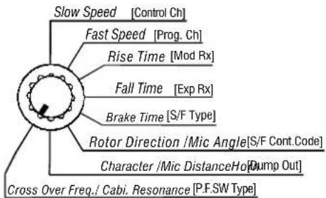
- Select P.F.SW Type using the Function Selector.
text_image
Slow Speed [Control Ch] Fast Speed [Prog. Ch] Rise Time [Mod Rx] Fall Time [Exp Rx] Brake Time [S/F Type] Rotor Direction /Mic Angle[S/F Cont.Code] Character /Mic DistanceHolt [Jump Out] Cross Over Freq./ Cabi. Resonance [P.F.SW Type]- Use the VALUE Rotary Knob to select the value you want.
text_image
UL VALUE DOWN UP♦ Presets
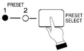
Because your Leslie Speaker has a number of Advanced Features allowing you to change the speaker's sound and performance, you may find it helpful to "bundle" your favorite settings together. Therefore, your Leslie Speaker has two Presets which allow you to save two different combinations of Advanced Feature settings for easy retrieval later.
TRY THIS:
- Select the Preset Number using the PRESET Touch Button.
flowchart
graph TD
    A["1"] --> B["2"]
    B --> C[" "]
    style A fill:#000,stroke:#fff,color:#fff
    style B fill:#fff,stroke:#000
    style C fill:#fff,stroke:#000
-
Make whatever changes you would like to the Leslie Advanced Features using the procedures described on the previous pages.
-
Touch and Hold the red MEMORY Touch Button for approximately 1 second.
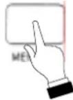
- The LED of the Preset you selected will flash, indicating that your Preset is now saved.
In addition, you may select Presets using a Foot Switch. Simply plug a Foot Switch into the PRESET Foot Switch receptacle located on the back of your Leslie Speaker.
NOTE: You may also select Presets using Program Numbers. To do this, you must enable the MIDI Program Number and send Program # 1 or 2 to select Preset 1 or 2. For more information, please see page 19.
♦ Default
To restore the default settings of your Leslie Speaker:
-
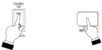
Make sure the power to the Leslie is turned "OFF."
-
Touch and Hold the red MEMORY Touch Button.

- Continue to hold the MEMORY Touch Button, and turn the Power to the Leslie "ON."
text_image
Power MOSThe factory default settings have now been restored.
controlling the speaker from another instrument via MIDI
Your Leslie Speaker gives you the capability to control the Leslie parameters (Slow Speed, Fast Speed, Rise Time, Fall Time, Brake Time, Horn Resonance, Microphone Angle, Microphone Distance) via MIDI. The Low Rotor is controlled through software via DSP, while the Horn Rotor uses a special brushless DC motor which responds to incoming MIDI Controller data. Below is an example of how to do this.
In this way:
- Non-Hammond keyboards such as synthesizers, MIDI master keyboards, etc., can control the rotors and sound of this Leslie Speaker without going through the 11-pin Leslie interface.
- Hammond Organ models which have Leslie parameter controls in the Information Center Display such as XB-1, XK-2, XE-1, CMS-100-series, A-305, and XT/XI I-series home organs can control the rotors and sound characteristics of the Leslie Speaker in addition to the built-in digital Leslie simulator.
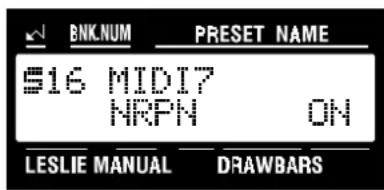
NOTE: In order for the above to work, the MIDI NRPN must be "ON." Please consult the Owner's Playing Guide for your instrument for instructions on how to do this.)
Example of Controlling the Advanced Features of the Leslie via MIDI
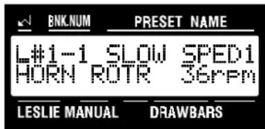
The example below applies to all the Advanced Features. The XK-2 screens are shown; however, the related screens of the Hammond XB-1, XM-1, XT/XI I-series, XE-1, CMS-100 series and A-305 will also control the Advanced Features. The example shown is Slow Speed.
TRY THIS:
- Turn MIDI NRPN "ON" using the MIDI Edit Menu of your organ.
text_image
BNK.NUM PRESET NAME $16 MIDI7 NRPN ON LESLIE MANUAL DRAWBARS- Select the Advanced Feature you want to change. For this example, we will use Slow Speed.
text_image
BNK.NUM PRESET NAME L#1-1 SLOW SPED1 HORN ROTR 36rpm LESLIE MANUAL DRAWBARS- Now select the option you wish by doing the following:
Use either the PAGE “▶” or the PAGE “◀” Select Touch Button to select between Horn and Low Rotors.
Use the VALUE “▲” Select Touch Button to increase the number setting.
Use the VALUE "▼" Select Touch Button to decrease the number setting.
You can use this same method to control whatever Advanced Features your Hammond Organ gives you access to via the Information Center Display.
NOTE: All of the Advanced Features available on your Leslie Speaker may not be able to be controlled using your Hammond Organ. Also, your Hammond Organ may not give you the full range of choices available when you use the controls of the Leslie Speaker to program the Advanced Features.
♦ SPECIAL NOTE: Connecting older digital Hammond Organs via MIDI
Connecting using the XB-2, XB-5 or A-205
When connecting the above instruments, the ONLY Advanced Feature you will be able to utilize is, the ability to control the speed of the rotors using the Modulation Wheel. Because the control codes are different on these organs, none of the Information Center-driven Advanced Features will work through the Leslie.
Connecting the XB-3/XC-3 or XB-3A/XC-3A
Because these organs have no Information Center-driven Leslie Advanced Features, the only Advanced Feature you will be able to utilize is, the ability to control the speed of the rotors using the Modulation Wheel. The CU-2 Control Unit must be connected in order to use this feature, since the Modulation Wheel is part of this control unit.
Also, the second wheel must be programmed as a Modulation Wheel and not as the Leslie Speed Control switch. Please consult the Owner's Playing Guide of the organ for instructions on how to do this.
Preset Parameters
| Category Parameter | NRPN Adr. | DATA Range | Default | |||||
| LSB(62) | MSB(63) | MSB(06) | LSB(26) | Preset1 | Preset2 | |||
| Horn Rotor | Slow Speed | 7F | 00 | 0 - 99 (0,24-318rpm) | *1 - 5(36rpm) | 5(36rpm) | ||
| Fast Speed | 7F | 02 | 1 - 27(375-450rpm) | *2 - 9(40rpm) | 7(393rpm) | |||
| Rise Time | 7F | 04 | 0-39(0.2-12.5s) | *5 - 2.2 | 1.8s | |||
| Fall Time | 7F | 06 | 0-39(0.2-12.5s) | *5 - 1.2 | 1.0s | |||
| Brake Time | 7F | 08 | 0-39(0.2-12.5s) | *5 - 1.4 | 1.2 | |||
| Direction | 7F | 0C | 0,1(Left,Right) - Right Right | |||||
| Horn Character | 7F | 0D | 0-3 | *7 - 1.0k | Flat | |||
| Low Rotor | Slow Speed | 7F | 01 | 0-9(0,24-48rpm) | *3 - 5(36rpm) | 5(36rpm) | ||
| Fast Speed | 7F | 03 | 1-21(372-431rpm) | *4 - 9(40rpm) | 6(391rpm) | |||
| Rise Time | 7F | 05 | 0-24(0.5-12.5s) | *6 - 5.5 | 5.0s | |||
| Fall Time | 7F | 07 | 0-24(0.5-12.5s) | *6 - 6.0 | 3.0s | |||
| Brake Time | 7F | 09 | 0-24(0.5-12.5s) | *6 - 8.5 | 2.0s | |||
| Mic Angle | 7F | 0A | 0-6(0°-180°) | *8 | -180° | 120° | ||
| Mic Distance | 7F | 0B | 0-8(0.2m-2.7m) | *9 - 1.8m | 1.2m | |||
| Horn&Low Rotor | CrossOver Frequency | 7F | 0E | 0-2(0.7k,0.8k,1.0k) - | 0.7k 0.7k | |||
| Cabinet Resonance | 7F | 0F | 0,1(Off,On) | - Off On | ||||
System Parameters
| Category Parameter | NRPN Adr. | DATA Range | Default | |||
| LSB(62) | MSB(63) | MSB(06) | LSB(26) | |||
| Preset | Preset Number | 7F | 10 | 0,1(Preset1,Preset2) | - 0(Preset1) | |
| MIDI System | Control Channel | 7F | 11 | 0-16(1-16channel,Off) | - 0(1Channel) | |
| Program Channel | 7F | 12 | 0-16(1-16channel,Off) | - 16(Off) | ||
| Modulation Receive | 7F | 13 | 0,1(Off,On) | - 1(On) | ||
| Exp Receive | 7F | 14 | 0,1(Off,On) | - 0(Off) | ||
| Slow/Fast Control Type | 7F | 15 | 0,1(UnLatch,Latch) | - 1(Latch) | ||
| Slow/Fast Control Code | 7F | 16 | 0-99 | - 64 | ||
| Other | Preset Foot Switch Type | 7F | 17 | 0,1(UnLatch,Latch) | - 0(UnLatch) | |
| Leslie Mode | 7F | 18 | 0-2(Slow,Fast,Brake) | - 0(Slow) | ||
*1 Horn Slow Speed
| Data Dec | LSB Hex D | Date Hex | m | |||
| 0 | 00 | 0 | 50 | 32 | 172 | |
| 1 | 0 | 1 | 24 | 51 | 33 | 174 |
| 2 | 0 | 2 | 27 | 52 | 34 | 178 |
| 3 | 0 | 3 | 31 | 53 | 35 | 181 |
| 4 | 04 | 33 | 54 | 36 | 183 | |
| 5 | 0 | 5 | 36 | 55 | 37 | 187 |
| 6 | 0 | 6 | 40 | 56 | 38 | 189 |
| 7 | 0 | 7 | 42 | 57 | 39 | 193 |
| 8 | 0 | 8 | 46 | 58 | 3A | 195 |
| 9 | 0 | 9 | 48 | 59 | 3B | 198 |
| 10 | 0A 50 | 60 3C 202 | ||||
| 11 | 0B 52 | 61 3D 204 | ||||
| 12 | 0C | 57 | 62 | 3E | 208 | |
| 13 | 0D 61 | 63 3F 20 | ||||
| 14 | 0E 63 | 64 40 213 | ||||
| 15 | 0F 65 | 65 41 217 | ||||
| 16 | 10 68 | 66 42 219 | ||||
| 17 | 11 72 | 67 43 223 | ||||
| 18 | 12 | 76 | 68 | 44 | 225 | |
| 19 | 13 78 | 69 45 229 | ||||
| 20 | 14 80 | 70 46 231 | ||||
| 21 | 15 84 | 71 47 234 | ||||
| 22 | 16 | 87 | 72 | 48 | 238 | |
| 23 | 17 | 91 | 73 | 49 | 240 | |
| 24 | 18 93 | 74 4A 2-3 | ||||
| 25 | 19 97 | 75 4B 2-7 | ||||
| 26 | 1A | 100 | 76 | 4C | 249 | |
| 27 | 1B | 102 | 77 | 4D | 253 | |
| 28 | 1C 10 | 6 78 4E 255 | ||||
| 29 | 1D 10 | 8 79 4F 258 | ||||
| 30 | 1E 11 | 2 80 50 262 | ||||
| 31 | 1F | 114 | 81 | 51 | 264 | |
| 32 | 20 11 | 7 82 52 267 | ||||
| 33 | 21 12 | 83 53 271 | ||||
| 34 | 22 12 | 84 54 273 | ||||
| 35 | 23 | 127 | 85 | 55 | 276 | |
| 36 | 24 13 | 86 56 280 | ||||
| 37 | 25 13 | 87 57 282 | ||||
| 38 | 26 13 | 88 58 286 | ||||
| 39 | 27 | 138 | 89 | 59 | 288 | |
| 40 | 28 14 | 90 5A 291 | 94 | 5E | ||
| 41 | 29 14 | 91 5B 295 | ||||
| 42 | 2A 14 | 7 92 5C 297 | ||||
| 43 | 2B 15 | 93 5D 300 | ||||
| 44 | 2C | 153 | 302 | |||
| 45 | 2D 15 | 7 95 5F 306 | ||||
| 46 | 2E | 160 | 96 | 60 | 309 | |
| 47 | 2F 16 | 2 97 61 311 | ||||
| 48 | 30 | 166 | 98 | 62 | 315 | |
| 49 | 31 | 168 | 99 | 63 | 318 |
*2 Horn Fast Speed
| Data LSB | rpm | |
| Dec | Hex | |
| 1 | 01 | 376 |
| 2 | 02 | 378 |
| 3 | 0 | 3 |
| 4 | 0 | 4 |
| 5 | 0 | 5 |
| 6 | 0 | 6 |
| 7 | 0 | 7 |
| 8 | 0 | 8 |
| 9 | 09 | 400 |
| 10 | 0A | 402 |
| 11 | 0B | 406 |
| 12 | 0C | 408 |
| 13 | 0D | 411 |
| 14 | 0E | 414 |
| 15 | 0F | 418 |
| 16 | 10 | 421 |
| 17 | 11 | 424 |
| 18 | 12 | 427 |
| 19 | 13 | 430 |
| 20 | 14 | 431 |
| 21 | 15 | 435 |
| 22 | 16 | 438 |
| 23 | 17 | 442 |
| 24 | 18 | 444 |
| 25 | 19 | 447 |
| 26 | 1A | 450 |
| 27 | 1B | 452 |
*5 Horn Rotor Time
| Data LSB | time Dis play | ||
| Dec | Hex second | ||
| 0 | 0 | 0 | 0.2 |
| 1 | 01 | 0.4 | 0.4 |
| 2 | 0 | 2 | 0.6 |
| 3 | 0 | 3 | 0.8 |
| 4 | 0 | 4 | 1.0 |
| 5 | 05 | 1.2 | 1.2 |
| 6 | 0 | 6 | 1.4 |
| 7 | 0 | 7 | 1.6 |
| 8 | 08 | 1.8 | 1.8 |
| 9 | 09 | 2.0 | 2.0 |
| 10 | 0A 2.2 | 2.2 | |
| 11 | 0B 2.4 | 2.4 | |
| 12 | 0C 2.6 | 2.6 | |
| 13 | 0D | 2.8 | 2.8 |
| 14 | 0E 3.0 | 3.0 | |
| 15 | 0F 3.2 | 3.2 | |
| 16 | 10 3.4 | 3.4 | |
| 17 | 11 3.6 | 3.6 | |
| 18 | 12 3.8 | 3.8 | |
| 19 | 13 4.0 | 4.0 | |
| 20 | 14 4.2 | 4.2 | |
| 21 | 15 4.4 | 4.4 | |
| 22 | 16 | 4.6 | 4.6 |
| 23 | 17 4.8 | 4.8 | |
| 24 | 18 5.0 | 5.0 | |
| 25 | 19 5.5 | 5.5 | |
| 26 | 1A | 6.0 | 6.0 |
| 27 | 1B 6.5 | 6.5 | |
| 28 | 1C 7.0 | 7.0 | |
| 29 | 1D 7.5 | 7.5 | |
| 30 | 1E | 8.0 | 8.0 |
| 31 | 1F 8.5 | 8.5 | |
| 32 | 20 9.0 | 9.0 | |
| 33 | 21 9.5 | 9.5 | |
| 34 | 22 | 10.0 | 10 |
| 35 | 23 | 10.5 | 10. |
| 36 | 24 | 11.0 | 11 |
| 37 | 25 | 11.5 | 11. |
| 38 | 26 | 12.0 | 12 |
| 39 | 27 | 12.5 | 12. |
*6 Low Rotor Time
| Data LSB | time Dis | play | ||
| Dec | Hex s | second | ||
| 0 | 0 | 0 | 0.5 | 0.5 |
| 1 | 01 | 1.0 | 1.0 | |
| 2 | 0 | 2 | 1.5 | 1.5 |
| 3 | 0 | 3 | 2.0 | 2.0 |
| 4 | 0 | 4 | 2.5 | 2.5 |
| 5 | 05 | 3.0 | 3.0 | |
| 6 | 0 | 6 | 3.5 | 3.5 |
| 7 | 0 | 7 | 4.0 | 4.0 |
| 8 | 08 | 4.5 | 4.5 | |
| 9 | 09 | 5.0 | 5.0 | |
| 10 | 0A 5.3 | 5.5 | ||
| 11 | 0B 6.0 | 6.0 | ||
| 12 | 0C 6.3 | 6.3 | ||
| 13 | 0D | 7.0 | 7.0 | |
| 14 | 0E 7.3 | 7.5 | ||
| 15 | 0F 8.0 | 8.0 | ||
| 16 | 10 8.5 | 8.5 | ||
| 17 | 11 9.0 | 9.0 | ||
| 18 | 12 9.5 | 9.5 | ||
| 19 | 13 | 10.0 | 10 | |
| 20 | 14 | 10.5 | 10. | |
| 21 | 15 | 11.0 | 11 | |
| 22 | 16 | 11.5 | 11. | |
| 23 | 17 | 12.0 | 12 | |
| 24 | 18 | 12.5 | 12. | |
*7 Horn Character
| Data LSB | Character | Display | |
| Dec | Hex | ||
| 0 | 0 | 0 1.0k | 1.0 |
| 1 | 0 | 1 1.5k | 1.5 |
| 2 | 02 | 2.0k | 2.0 |
| 3 | 0 | 3 flat | FI |
\*3 Low Rotor Slow Speed
*Low Rotor Slow Speed 0-9 (0,24-48 Rpm)
\*4 Low Rotor Fast Speed
*Low Rotor Fast Speed 1-21(372-431 Rpm)
*8 Mic Angle
| Data LSB | Character | Display | |
| Dec | Hex | ||
| 0 | 00 | 0^ | 0 |
| 1 | 0 | 1 ^30 | 30 |
| 2 | 0 | 2 ^60 | 60 |
| 3 | 0 | 3 ^90 | 90 |
| 4 | 04 | 120 ^ | 12. |
| 5 | 0 | 5 150 | 15. |
| 6 | 0 | 6 180 | 18. |
*9 Mic Distance
| Data LSB | Character | Display | |
| Dec | Hex | ||
| 0 | 00 | 0.3 | 0.3 |
| 1 | 0 | 1 0.6 | 0.6 |
| 2 | 02 | 0.9 | 0.9 |
| 3 | 0 | 3 1.2 | 1.2 |
| 4 | 04 | 1.5 | 1.5 |
| 5 | 0 | 5 1.8 | 1.8 |
| 6 | 06 | 2.1 | 2.1 |
| 7 | 07 | 2.4 | 2.4 |
| 8 | 08 | 2.7 | 2.7 |
MIDI Information
[Channel Voice Message]
Control Change
The value set by the Control Change is not reset even when
Program Change messages etc. are received.
Modulation(Leslie Speed)
| Status 2 | nd Byte 3rd | Byte |
| Bn 01 vv |
n=MIDI Channel Number: 0 - F(Ch.1 - 16)
vv=Modulation Depth: 00 - 7F
Data Entry
| Status 2 | nd Byte 3rd | Byte |
| Bn 06 mm | (MSB) | |
| Bn 26 ll (L) | SB) |
n=MIDI Channel Number: 0 - F(Ch.1 - 16)
mm,ll=Value for the Parameter designated by NRPN.
Expression(Leslie Speed)
| Status 2nd Byte 3rd Byte | ||
| Bn 0B | VV | |
n-MIDI Channel Number: 0 - F(Ch.1 - 16)
vv=Expression:
00 - 7F(0 - 127)
Default Value = 7F(127)
Korg Rotary Fast Code
| Status 2 | nd Byte 3rd | Byte |
| Bn 52 vv |
n=MIDI Channel Number: 0 - F(Ch.1 - 16)
vv=Control Value: 00 - 7F(0 - 127) 0-63 = Off, 64-127 = On
Korg Rotary Brake Code
| Status 2nd Byte 3rd Byte | ||
| Bn 53 vv | ||
n=MIDI Channel Number: 0 - F(Ch.1 - 16)
vv-Control Value: 00 - 7F(0 - 127) 0-63 = Off, 64-127 = On
Hold 1(Leslie Slow/Fast initial Code)
| Status 2nd Byte 3rd Byte | ||
| Bn 40 vv | ||
n=MIDI Channel Number: 0 - F(Ch.1 - 16)
vv-Control Value: Leslie Slow/Fast Control Type=Mormentary:
00 - 7F(0 - 127) 0-63 = Off, 64-127 = On
Leslie Slow/Fast Control Type=Altarnate:
00 - 7F(0 - 127) 64-127 = Latch
NRPN MSB/LSB
| Status 2 | nd Byte 3rd | Byte |
| Bn 63 mm | (MSB) | |
| Bn 62 ll (L SB) | ||
n=MIDI Channel Number: 0 - F(Ch.1 - 16)
mm=Upper Byte of the Parameter Number designated by NRPN[MSB].
ll=Lower Byte of same[MSB].
NRPN- "Non Registered Parameter Number"
The expansive range named NRPN is provided in the Control Change, which function is specific on each equipment and not defined in the MIDI Standard.
When you use it, designate the parameter to control, by gibing NRPN MSB and NRPN LSB (cc#98 and 99), and the set the value of the designated parameter by the Data Entry MSB(cc#6).
Once the NRPN parameter is designated, all the data entry received into the same channel after that is regarded as the change of the value of the parameter. To avoid any mis-operation, we suggest you to set RPN Null (RPN = 7F 7F), after setting the necessary parameter value.
Program Change
| Status | 2nd Byte |
| Cn | pp |
n=MIDI Channel Number: 0 - F(Ch.1 - 16)
pp=Program Number 0:preset1 1:preset2
Program Channel: Change Preset.
System Exclusive Message
Memory Dump
| F0 | System Exclusive |
| 55 | SUZUKI ID |
| 10 | Device ID |
| 10 | Model ID MSB |
| 12 | Model ID LSB |
| 11 | Command: Data Packet |
| [TYPE] | Data Type00h= Memory Dump |
| [PNH] | Packet Number MSB |
| [PNL] | Packet Number LSB |
| [DATA] | 128 Bytes Data256 Bytes nibblized ASCIIex: 7Eh = 37h, 45h |
| [CHD] | Check DigitLower 7 bits of XOR [DATA] |
| F7 | End of Exclusive |
Roland Leslie Slow Fast
| F0 | System Exclusive |
| 41 | Roland ID |
| 10 | Device ID |
| 00 | Model ID MSB |
| 08 | Model ID LSB |
| 12 | Command ID |
| 02 | address1 |
| 00 | address2 |
| 10 | address3 |
| 3D | address4 |
| [DATA] | 00:Slow 01:Fast |
| [SUM] | no check |
| F7 | End of Exclusive |
Leslie
Model: 2101/2102/2103
MIDI Implementation Chart
Date: 22-Mar-2002
Version: 1.0
| Function | Transmitted | Recognized | Remarks | |
| Basic Channel | DefaultChanged | 11 - 16 1 - 16 Program | 1Channel=Off | ControlChannel=1 |
| Mode | DefaultMessagesAltered | 3X***** X | 3X | |
| NoteNumber | : True Voice | X***** X | X | |
| Velocity | Note ONNote OFF | XX | XX | |
| After Touch | Key'sCh's | XX | XX | |
| Pitch Bender | X | X | ||
| Control Change | 16,381182836498,99 | OO O Data EntryXXO Korg Rotary FastX O Korg Rotary BraceX O Hold1(Slow/Fast)O | OOO | M oExpression(LeslieSpeed)N R |
| Program Change : True # | O 0 - 1 O 0 - 1***** O 0 - 1 | |||
| System Exclusive | O | O | ||
| System Common : Song Position : Song Select : Tune | XXX | XXX | ||
| System Real Time : Commands | XX | XX | ||
| Aux Messages : Local On/Off : All Notes Off : Active Sense : Reset | XXX | XXX | ||
Mode 1: OMNI ON, POLY Mode 2: OMNI ON, MONO O: Yes
Mode 3: OMNI OFF, POLY Mode 4: OMNI OFF, MONO
X: No
HAVE YOUR SERVICE PERFORMED BY:
An authorized Leslie Speaker dealer orauthorized service technician. If you still need further assistance, contact Hammond at the following addresses:
In the United States contact:
In Europe contact:
All other countries contact:
HAMMOND SUZUKI USA, Inc.
733 Annoreno Dr.
Addison, IL 60101
UNITED STATES
HAMMOND SUZUKI EUROPE B.V.
IR. D.S. Tuynmanweg 4A 4131 PN Vianen
THE NETHERLANDS
HAMMOND SUZUKI Ltd.
25-12, Ryoke 2 Chome
Hamamatsu 430-0852
(Shizuoka)
JAPAN
Email:info@hammondsuzuki.com
Website:www.hammondsuzuki.com
Technical materials are available and can be obtained by mailing a request to the appropriate address listed above marked ATTENTION: SERVICE DEPARTMENT.
Manufacturer:
SUZUKI MUSICAL INSTRUMENT MFG. CO., Ltd
25-12, Ryoke 2 Chome
Hamamatsu 430-0852 (Shizuoka)
JAPAN