
MEGA-DSP15 - Loudspeaker Monacor - Free user manual and instructions
Find the device manual for free MEGA-DSP15 Monacor in PDF.


| Product Type | Active 2-way speaker system with digital signal processor (DSP) |
| Model | MEGA-DSP15 |
| Amplifier Power (RMS) | Treble: 100 W, Bass: 500 W |
| Frequency Range (-6 dB) | 40 – 20,000 Hz |
| Maximum SPL | 123 dB |
| Bass Speaker | ∅ 38 cm (15") |
| Tweeter | Dynamic horn tweeter, voice coil ∅ 25.4 mm (1") |
| Input Sensitivity (LINE / AUX / MIC) | 1 V / 1 V / 50 mV (rated); 7 V / 5 V / 850 mV (max) |
| Input Impedance (LINE / AUX / MIC) | 16 kΩ / 8 kΩ / 2 kΩ |
| Directivity (-6 dB) | 90° × 60° (H × V) |
| Power Supply | 230 V~ / 50 Hz, max. 790 VA |
| Dimensions (W × H × D) | 416 × 678 × 454 mm |
| Weight | 25.5 kg |
| DSP Features | 10-band parametric EQ, limiter, signal delay, high-pass filter, presets, remote control via Ethernet |
| Inputs | 2× balanced (XLR/6.3 mm) for LINE A/MIC and LINE B; 1× unbalanced stereo AUX (RCA) |
| Outputs | MIX OUT (XLR), AC LINK (PowerCon) for daisy-chaining |
| Mounting Options | 35 mm stand sleeve, M8 threaded inserts for flying or brackets |
| Tweeter Rotation | Rotatable by 90° for horizontal operation |
| Cleaning | Use a dry, soft cloth only; no water or chemicals |
| Ambient Temperature | 0 – 40 °C |
| Safety | Indoor use only; do not cover vents; disconnect if damaged |
| Spare Parts & Repairability | Professional series; spare parts available from Monacor; servicing by skilled personnel only |
Frequently Asked Questions - MEGA-DSP15 Monacor
User questions about MEGA-DSP15 Monacor
0 question about this device. Answer the ones you know or ask your own.
Ask a new question about this device
Download the instructions for your Loudspeaker in PDF format for free! Find your manual MEGA-DSP15 - Monacor and take your electronic device back in hand. On this page are published all the documents necessary for the use of your device. MEGA-DSP15 by Monacor.
USER MANUAL MEGA-DSP15 Monacor
Active Speaker System with remotely controllable signal processor


MEGA-DSP 08
MEGA-DSP 10
MEGA-DSP 12
MEGA-DSP 15
6.3.4 Firmware Update 6
6.3.5 BGM-Player 6
6.3.6 Programm beenden....6
6.3.4 Firmware Update
⑧ Einschalt-Preset
6.6.5 Ruhemodus
⑨ Ruhe-Verzögerung
Change Unit Configuration:
⑩ Sperroptionen
6.6.7 Systeminformationen
Before switching on ...
Please read these operating instructions carefully prior to operating the unit. Thus, you will get to know all functions of the unit, operating errors will be prevented, and yourself and the unit will be protected against any damage caused by improper use. Please keep the operating instructions for later use.
Contents
1 Operating Elements and Connections .... 13
2 Safety Notes 13
3 Applications 13
4 Setup and Connection ..... 13
4.1 Turning the tweeter ..... 13
4.2 Connecting a signal source ..... 14
4.2.1 Selecting the input sensitivity ..... 14
4.3 Signal outputs 14
4.4 Computer 14
4.5 Mains connection ..... 14
5 Operation 14
5.1 Operation without a computer ..... 14
5.1.1 Calling up presets ..... 14
5.1.2 Showing system information ..... 14
5.1.3 Deactivating a lock ..... 14
5.1.4 Locking unit, changing password ..... 14
6 Remote Control by Means of a Computer .... 15
6.1 Installing the PC software ..... 15
6.2 Establishing a network connection ... 15
6.3 Control program 15
6.3.1 Unit groups ..... 16
6.3.1.1 Creating a new group ..... 16
6.3.1.2 Deleting a group ..... 16
6.3.2 Changing the program password ..... 16
6.3.3 Demo mode ..... 16
6.3.4 Firmware update 16
6.3.5 BGM player 16
6.3.6 Exiting the program ..... 16
6.4 Configuring the speaker ..... 16
6.4.1 Setting the gain ..... 17
6.4.2 Muting the input ..... 17
6.4.3 Sound correction 17
6.4.3.1 Frequency response ..... 17
6.4.4 Limiter 18
6.4.5 Signal delay 18
6.4.6 High pass filter (LOW CUT) ..... 18
6.4.7 Linking inputs ..... 18
6.5 Managing configurations ..... 18
6.5.1 Loading a preset 18
6.5.2 Saving a preset 18
6.5.3 Saving a preset on the computer ..... 18
6.5.4 Loading a preset from the computer .. 18
6.5.5 Saving all presets on the computer . . . 18
6.5.6 Restoring a set of presets ..... 18
6.5.7 Restoring factory presets ..... 19
6.6 Additional settings ..... 19
6.6.1 Changing the name ..... 19
6.6.2 Changing the password ..... 19
6.6.3 Changing network settings ..... 19
6.6.4 Defining preset for switch-on ..... 19
6.6.5 Standby mode ..... 19
6.6.6 Options for a locked speaker system .. 19
6.6.7 System information ..... 20
6.6.8 Closing the configuration window .... 20
7 Specifications 20

1 Operating Elements and Connections
1 Status LEDs:
POWER Power LED
SIGNAL A Signal A after gain control
SIGNAL B Signal B after gain control
LIMITER Level limiting active
PROTECT Protective circuit active
2 Button MENU to select a menu item and to confirm user input
3 Button ESC to exit a menu and to cancel a function
4 LC display
5 Knob MASTER VOLUME to adjust the volume of input channel A (gain control)
6 Knob SELECT/ ENTER to adjust the volume of input channel B (gain control) and to select a preset and change values in the menu
7 Status LEDs LINK /ACT for the Ethernet connection (connection and activity indication)
8 RJ45 jack for the Ethernet connection to configure the signal processor by means of a computer
9 Selector switch for the input sensitivity of input LINE A / MIC (10)
MIC = microphone
LINE = line-level signal source
The LED indicator next to the switch lights up when MIC is selected
10 Input LINE A / MIC as combined XLR / 6.3 mm jack, and an XLR connection underneath to transmit the input signal, e. g. to another speaker system
11 Input LINE B as combined XLR / 6.3 mm jack, and an XLR connection underneath to transmit the input signal, e. g. to another speaker system
12 Input AUX as RCA jacks for input channel B
13 XLR output MIX OUT with mixed signal of the inputs A and B to be transmitted, e. g. to another speaker system
14 Cooling fins
15 Power switch
16 PowerCon® mains output jack AC LINK to connect another speaker system of the MEGA-DSP series (chapter 4.5)
17 PowerCon ® mains input jack AC INPUT for connection to a socket (230 V\~ / 50 Hz)
2 Safety Notes
This unit corresponds to all relevant directives of the EU and is therefore marked with C€.
WARNING

The unit uses dangerous mains voltage (230 V\~). Leave servicing to skilled personnel only and do not insert anything into the air vents! Inexpert handling of the unit may result in electric shock.
Please observe the following items in any case:
- The unit is suitable for indoor use only. Protect it against dripping water and splash water, high air humidity and heat (admissible ambient temperature range: 0 – 40 °C).
- Do not place any vessel filled with liquid on the unit, e. g. a drinking glass.
- The heat generated inside the unit must be dissipated by air circulation; never cover the air vents of the housing and the cooling fins (14). Never position the rear side of the speaker system directly against a wall; always make sure the distance is sufficient.
- Do not operate the unit and immediately disconnect the mains plug from the socket
- if the unit or the mains cable is visibly damaged,
- if a defect might have occurred after the unit was dropped or suffered a similar accident,
- if malfunctions occur.
In any case the unit must be repaired by skilled personnel. - Never pull the mains cable to disconnect the mains plug from the socket; always seize the plug.
- For cleaning only use a dry, soft cloth; never use water or chemicals.
- No guarantee claims for the unit and no liability for any resulting personal damage or material damage will be accepted if the unit is used for other purposes than originally intended, if it is not correctly connected or operated, or if it is not repaired in an expert way.

If the unit is to be put out of operation definitively, take it to a local recycling plant for a disposal which is not harmful to the environment.
3 Applications
The speaker systems of the MEGA DSP series are high-performance active speaker systems in rugged wooden housings. They are suitable for a wide range of applications, e. g. for dances, for smaller stages or as monitor speakers for bands. The speakers are designed as 2-way systems. Each of them is provided with a separate amplifier for the bass speaker and tweeter ranges. The amplifiers are equipped with protective circuits against overload and overheating.
The speaker systems include two balanced signal inputs; one of them can be switched to microphone sensitivity. For the other input, unbalanced connections are available. Additional signal outputs allow, for example, for the connection of further active speaker systems.
The digital signal processor (DSP) is the core component of the MEGA-DSP series, offering numerous options for changing the sound, readjusting the delay time and limiting the dynamic range. The DSP can be remotely controlled via a computer network. Various configurations may be saved as presets in the speaker system and can thus be made available for standalone operations.
4 Setup and Connection
Place the speaker system on a firm ground, e. g. on the stage or on a table and align it to the ears of the listeners. Due to its bevelled housing, the speaker system can be used as a stage monitor, radiating diagonally upwards. If a microphone is to be used, do not direct the speaker towards the microphone and make sure that the distance between the speaker system and the microphone is sufficient; otherwise, an acoustic feedback (loud howling) may occur.
Alternatively, use the stand sleeve located on the lower side of the speaker system to place the speaker onto a standard speaker stand with a tube diameter of 35 mm (e. g. from the PAST series).
To support additional mounting options, the housing is provided with numerous M8 threaded jacks where, for example, mounting brackets (MHB-.../MVB-...) or the ring bolt delivered with the speaker system can be fastened. To use the M8 threaded jacks, remove the corresponding cover screws (hexagon socket screws).
When positioning the speaker system, always make sure that air is able to flow freely through the cooling fins (14) on the rear side of the system to provide sufficient cooling.
WARNING

Installations which are not made in an expert way are a hazard, especially if systems are suspended (flown) above persons. Therefore, the installation must only be made by expert personnel familiar with the valid standards and safety regulations.
The installation, especially the stability of the mounting connections, must be checked at regular intervals.
4.1 Turning the tweeter
If the speaker system is to be mainly operated in a horizontal position (e.g. as a floor monitor), the tweeter may be turned by 90° for a wider radiation of the high frequencies. For this purpose, remove the metal front (lateral screws), remove the four screws of the tweeter and retighten the tweeter in a position turned counterclockwise by 90°.
4.2 Connecting a signal source
Prior to connecting the speaker system or changing existing connections, switch off the speaker system and the units to be connected.
For the connections of a line-level signal source (e.g. CD player, mixer output), the following options are available:
- For balanced signals, the combined XLR / 6.3 mm jacks LINE A/ MIC (10) and LINE (11) [the contact configuration is printed on the unit, see figure].
- For unbalanced signals, the RCA jacks AUX (12) are suited. If the two RCA jacks or if the RCA jacks and the jack LINE B (11) are used together, the input signals will be mixed, creating a mono signal when a stereo signal source is connected. For a stereophonic sound reproduction, connect each stereo channel to a separate speaker system.
An unbalanced mono signal can also be connected to the jack LINE A/ MIC (10) or LINE B (11) by means of a 2-pole plug.
A microphone can be connected to the combined XLR / 6.3 mm jack LINE A/ MIC (10). The jack is provided for balanced signals for both plug types.
A microphone with an unbalanced output signal can be connected to the jack by means of a 2-pole plug.
To remove an XLR plug from the jack, press the PUSH lever.
4.2.1 Selecting the input sensitivity
If a microphone is connected to the input LINE A/MIC (10), switch the selector switch LINE / MIC (9) to the position MIC to increase the input sensitivity. The LED indicator next to the selector switch will light up. To connect a line-level signal source, switch the selector switch to the position LINE.
4.3 Signal outputs
The XLR jacks beneath the input jacks (10 and 11) are provided to transmit an input signal to additional speaker systems or to a recorder. The mixed signals of the inputs LINE A/ MIC, LINE B and AUX are additionally present at the jack MIX OUT (13).
4.4 Computer
To operate the speaker system by remote-control or to configure the presets, connect the speaker system to a single computer or to a computer network, using the jack ETHERNET (8) [125 chapter 6].
4.5 Mains connection
To provide the speaker system with power, connect the PowerCon® mains jack AC INPUT (17) to the 230 V mains using the mains cable supplied. After connecting the PowerCon® plug to the jack, turn the plug clockwise until it engages. To remove the plug, pull back the latch on the plug and turn the plug counter-clockwise.
Use the PowerCon ® mains output jack AC LINK (16) to connect an additional speaker system. Thus, a maximum of four speaker systems of the MEGA-DSP series can be connected with each other.
Note: A PowerCon ® plug must not be under load or voltage when it is connected or disconnected. Therefore, always first establish the PowerCon ® connection and then the mains connection, and always disconnect the mains connection prior to the PowerCon ® connection.
5 Operation
CAUTION: The volume is digitally adjusted by means of the two knobs (5, 6) or by remote control via the network, and cannot be changed or read before the unit is switched on. Therefore, the signal sources should be switched off when the initial adjustment of the unit at switch-on is not known.
Use the Power switch (15) to switch on the speaker system. The LED POWER (1) and the LED on the front panel of the speaker system light up. The upper line of the display (4) shows the name of the speaker system; the lower line shows the name of the current preset.
Once the connection to the control program on a computer has been established via the network, the lower line of the display shows Ethernet Active and it is no longer possible to make operations at the speaker system.
5.1 Operation without computer
For standalone operation, the speaker system may not be connected (via a network) to a computer running the control program.
1) Use the control "MASTER VOLUME" (5) to adjust the volume for the input LINE A/ MIC (10).
2) Use the control "SELECT/ENTER" (6) to adjust the volume for the inputs LINE B (11) and AUX (12).
The gain value adjusted (in dB) is shown on the display (4), e.g.:
In A Gain - 2 0. 0 0 dB
If both input channels are linked due to a preset, the upper line will show the following:
In AB Gain
In this case, each of the two controls will always adjust the volume of both channels.
CAUTION
Never adjust the amplifier to a very high volume. Permanent high volumes may damage your hearing! Your ear will get accustomed to high volumes which do not seem to be that high after some time. Therefore, do not further increase a high volume after getting used to it.
Functions of the status LEDs (1):
- The LEDs SIGNAL A and SIGNAL B will light up when a signal is present at the corresponding input and when the gain adjustment selected is not too low.
- The LED LIMITER will light up as soon as level limiting for an input channel is active.
- The LED PROTECT will light up as soon as the protective circuit responds, and will light up briefly each time the unit is switched on or off.
Note: All the adjustments made will be kept after switch-off, if the switch-on settings "Power on Preset" for the speaker system have been set to "Last Setting" (Chapter 6.6.4).
5.1.1 Calling up presets
Note: The factory settings provide this function to all users; however, the function can be locked by means of the setting menus (Chapter 6.6.6).
To call up a preset:
1) Press the button MENU (2) to show the following on the display (4): Load followed by the preset number in the first line, and the
name of the preset most recently selected in the second line.
The first five storage spaces are occupied by predefined presets; the remaining storage spaces can be configured as desired.
2) Turn the knob SELECT/ ENTER (6) to select the desired preset; then press the knob SELECT/ ENTER to confirm. The following message will appear on the display:
Load Preset? NO / yes
3) Turn the knob SELECT/ENTER to the right to load the preset. The following message will appear on the display:
Load Preset? no / YES
4) Press the knob SELECT/ ENTER. The preset is being loaded. During loading, the name of the preset is followed by *.
Pressing the button ESC (3) in the above steps or waiting for more than one minute will cancel the operation.
5.1.2 Showing system information
To show system information:
1) Press the button MENU (2) repeatedly until Version Info, IP Address or MAC Address appears on the display (4).
2) Turn the knob SELECT/ENTER (6) to show more information.
Pressing the button ESC (3) in the above steps or waiting for more than one minute will cancel the operation.
5.1.3 Deactivating a lock
Each time the speaker system is switched on, the speaker system is in a locked state providing only a limited range of operating options. The options available after switch-on can be defined on the computer in the settings of the speaker system ( chapter 6.6.6). Entering the password for the speaker system will deactivate the lock. The password is factory-set to "monacor" and can individually be changed for each speaker system ( chapter 6.6.2 or chapter 5.1.4).
1) Press the button MENU (2) repeatedly until Access Level appears on the display (4).
2) Turn the knob SELECT/ ENTER (6) to select the option Unlocked; then press the knob SELECT/ ENTER to confirm.Enter Password is shown on the display.
3) Turn the knob SELECT/ENTER to select the first password character for the speaker system; then press the knob SELECT/ ENTER to go to the next character position.
4) Proceed in the same way to enter the remaining password characters; however, do not press the knob after the last character has been selected. To correct a character, use the button ESC (3) to return to the previous character position.
5) When the password is complete, press the button MENU to confirm.
5.1.4 Locking unit, changing password
To lock the unit while in operation and, if required, change the password at the same time:
1) Press the button MENU (2) repeatedly until Access Level is shown on the display (4).
2) Turn the knob SELECT/ ENTER (6) to select the option **** Locked ****; then press the knob SELECT/ ENTER to confirm. The first line of the display shows Set Password, and the second line shows the current password of the speaker system.
3) To leave the password unchanged, press the button MENU and continue with step 6.
To assign a new password, overwrite the password shown on the display. To do so, turn the knob SELECT/ ENTER to select the first character of the new password, and then press the knob SELECT/ ENTER to go to the next character position.
4) Proceed in the same way to enter the remaining password characters; however, do not press the knob after the last character has been selected. To correct a character, use the button ESC (3) to return to the previous character position.
The maximum length of the password is 8 characters. If the new password is shorter than the old one, overwrite the old characters at the end of the password with space characters.
5) When the password is complete, press the button MENU to confirm. The display Confirm Password appears, asking you to confirm the password again.
6) Press the button MENU to confirm, or press the button ESC to correct the password.
Important: Make sure to remember the new password! If the password gets lost, it will not be possible to access the settings of the speaker system via the computer. The setting options available at the speaker system depend on the current access right settings ( chapter 6.6.6).
6 Remote Control by Means of a Computer
The speaker system includes a digital signal processor (DSP) which on the one hand splits the signal to the bass speaker and the tweeter and on the other hand offers a wide range of options for equalizing the frequency response, readjusting the delay time, and limiting the dynamic range. The DSP is factory-configured and ready to use. Five presets with different sound characteristics are available. The computer software delivered with the speaker system allows users to define their own settings, e.g. for adapting the system to the room acoustics. By means of the Ethernet interface (8), the speaker system can be connected to a single computer, a local computer network or, e.g. via a router, to larger computer networks (Internet). Network technology expertise is indispensable for the correct installation of the connection.
Note: A direct connection of the speaker system to the computer may require the use of a crossover cable or a corresponding adapter.
6.1 Installing the PC software
The installation of the control program supplied with the speaker system requires a computer equipped with the Windows XP operating system with Service Pack 2 or a later Windows version, or Mac OS X version 10.5.8 or later and an Ethernet interface. The screen resolution should be at least 1024 x 768 pixels. To install the PC software, start the installation program “[...] Controller.msi” or “[...] Controller.app” (for Mac OS X) on the CD supplied and follow the instructions of the installation program.
Windows is a registered trademark of Microsoft Corporation in the United States and other countries. Mac OS is a registered trademark of Apple Inc. in the United States and other countries.
6.2 Establishing a network connection
As per its factory settings, the speaker system automatically obtains network settings from a DCHP server in an existing network. If there is no DHCP server in the network connected, the speaker system will automatically assume the role of a DHCP server and will allocate an IP address to each of the other network members that are defined to automatically obtain network settings.
If only specific IP addresses are to be used, a particular IP address can be manually assigned to the speaker system (Chapter 6.6.3).
When in standalone operation, the most recently set IP address of a speaker system can be shown, using the menu ( chapter 5.1.2).
Note: The speaker system can only be configured by means of the program when the computer and the speaker system belong to the same sub-network. If they do not, it may be reasonable to first only connect the speaker system to a computer that automatically obtains its network settings from the speaker system. This connection can then be used to adapt the network settings of the speaker system to the settings of the designated network.
6.3 Control program
1) On the computer, call up the control program "DSP Controller".
A window appears, asking the user to enter the password for starting the program. The pre-defined password is "monacor". The user can change this password later.
2) Enter the password (without the inverted commas), observing the spelling.
If the password is not correctly entered, the message "Invalid password!" will be shown. Confirm this message and re-enter the password.
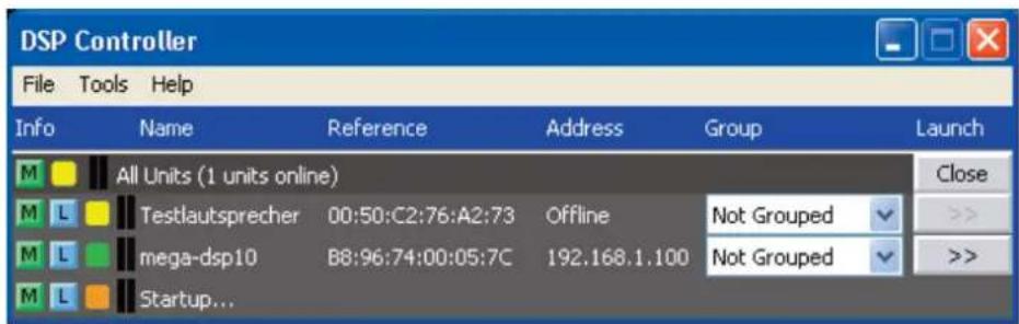
The overview window (fig. 2) appears, providing a list of all the speaker systems connected.
In the upper row "All Units", the information given in parentheses indicates the number of speaker systems that are currently online, i. e. actively connected with the computer.
The following rows provide functions and information with regard to the speaker systems. Each row includes the following columns:
Info
Button M to mute the speaker system. The button appears in red as long as the speaker system is muted. To reactivate the sound, click the button again. To mute all the speaker systems connected, click the button M in the row "All Units".
Button ☐ to locate and identify a speaker system. When the button has been clicked, the button as well as the status LEDs (1) on the rear panel of the corresponding speaker system flash for some seconds.
The colour field ○ indicates the connection status. It is green for units connected, and yellow for connections interrupted. When a new connection is established at switch-on, an additional row "Startup..." with an orange-coloured field appears at the end of the list.
The two vertical bars next to the coloured field are a simple level indication of the bass speaker and tweeter for the speaker system.
Name
Shows the name of the speaker system. The predefined name of the speaker system may be changed later ( chapter 6.6.1) for easier identification.
Reference
Shows the hardware address (MAC address) of the network interface of the speaker system. This address can be used to clearly identify a speaker system.
Address
Shows the IP address of a speaker system connected. If the connection is interrupted, "Offline" will be shown instead of the IP address.
Group
The list box field shows the group the speaker system currently belongs to. The list box can be used to assign the speaker to another group (group functions 15 chapter 6.3.1). The option "Not grouped" indicates that the speaker system is not assigned to any group.
Launch
If a speaker system is "online", the button [>>] can be used to call up the corresponding configuration window (fig. 5). To hide the list of speaker systems, click the button [Close]; to show the list, click the button [Open].
② Overview window

③ Overview window with group
6.3.1 Unit groups
Multiple speaker systems may be grouped so that they can be controlled (e. g. muted) simultaneously. Changes made to the settings of a speaker system in a group will automatically apply to all speaker systems of this group. It is always possible to assign a speaker system to another group.
6.3.1.1 Creating a new group
1) To create a new group, call up the menu item "Tools ➕ New Group".
2) In the window displayed, enter the desired group name in the field "Enter the name of the new group."
At the end of the list of speaker systems, an additional row for the group appears (row "Group: ...").
3) In each row of the speaker system to be included in the group, select the new group from the list in the column "Group".
This procedure can also be used at any time to remove a speaker system from a group (select „Not Grouped“) or to assign a speaker box to another group.
The row "Group: ..." indicates the number of speaker systems (members) that currently belong to the group.
4) Use the button [Open] at the end of the row "Group: ..." to show a list of all group members beneath the row; use the button [Close] to hide the list (fig. 3 – the list includes two members).
6.3.1.2 Deleting a group
To delete a group, click the button [Delete] (fig. 3) in the row of this group. A confirmation box appears, asking you to confirm the deletion. If the group to be deleted includes speaker systems, an additional note will let you know that the entry "Not Grouped" will be assigned to the speaker systems.
6.3.2 Changing the program password
To change the password for starting the program:
1) Call up the menu item „Tools ➕ Change Software Password“.
2) In the window displayed, enter the current password in the field "Enter Old Password:" (the pre-defined password is "monacor").
3) In the window displayed, enter the new password in the field "Enter New Password:".
4) In the window displayed, re-enter the password in the field "Confirm New Password":. Make sure to remember the password!
6.3.3 Demo mode
If no speaker system is connected to the computer, a virtual speaker system can be created for demonstration purposes. To do so, call up the menu item "Tools ➤ Enter Demo Mode".
In the list, a virtual speaker system named "Mega DSP" with the designation "DEMO..." in the field "Reference" is shown. As with real speakers, the configuration window can be called up by means of the button [>>] (fig. 5).
To remove the virtual speaker system from the list, call up the menu item "Tools ▶ Leave Demo Mode".
6.3.4 Firmware update
To ensure a smooth communication between the control program and the speaker system, both units must be equipped with matching firmware versions. If the control program is newer, the firmware (operating system) of the speaker system may be updated by means of the control program. With this update, all settings in the speaker system will get lost. To keep the settings, save them on the computer (chapter 6.5.5) before starting the update.
Note: Firmware updates are performed at your own risk. After a firmware update, the functions of the unit may differ from those described in this instruction manual.
CAUTION: Switch off the signal sources or reduce their output level so that the volume is not unexpectedly high after the settings have been reset.
To update the firmware of a speaker system, call up the menu item "Tools ▶ Enable Update". On the right-hand side of the list, the column "Update" appears.
1) In the row of the speaker system to be updated, click the button [>>] in the column "Update".
2) A message appears which informs the user that it is not allowed to switch off the speaker system or to interrupt the connection during the multi-step update process. If the update fails, it must be started again.
Click the button [OK] to start the update, or click [Cancel] to cancel the update.
3) Upon completion of the update, another message appears. Confirm this message.
If the program determines that the firm-ware of the speaker system is up to date, the settings will not be reset to the factory set-tings.
4) To reset the model-specific factory settings (preset 1 - 5), call up the configuration window of the speaker system and select the
function "Hardware Load Factory Presets" (chapter 6.5.7).
To hide the column "Update" in the list, call up the menu item "Tools ➤ Disable Update".
Note: Resetting to the factory settings will also affect the network settings and the password of the speaker system; i. e. it may initially not be possible to access the speaker system via the computer.
6.3.5 BGM player
Use the menu item "Tools ➕ BGM Player ➕ Open File/Open Directory" to call up a small utility program for playing audio files on the computer. "Open File" will play a single file; "Open Directory" will play all files included in the directory.
To play audio files on a speaker system, connect the audio output of the computer to the audio input (12) of the speaker system to be used.
6.3.6 Exiting the program
To exit the program, call up the menu item "File" or close the program window.
6.4 Configuring the speaker CAUTION!
Combined with the control program, the signal processor is an effective tool for making very detailed but also major changes to the transmission properties of the speaker system.
Therefore, each modification to the parameters should be performed with care and expertise. At the worst, extreme changes to the settings may damage the speaker system.
1) To configure a speaker system, click the button [>>] in the column "Launch" of the list (figs. 2, 3).
2) A dialog window appears. The name of the corresponding speaker system and its MAC address are shown in the list field.
If desired, select another speaker system.
3) In the field beneath "Password", enter the password for the speaker system selected. The password is factory-set to "monacor" and can individually be changed for each speaker system (chapter 6.6.2 or chapter 5.1.4).
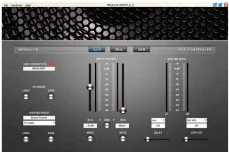
4) The main window (fig. 5) for the speaker system selected appears. The colour field on the left-hand side, next to UNIT CONNECTION, indicates the connection status of the speaker system. When the colour field is green, a data connection is established. A red colour field indicates that the connection is interrupted and that it is not possible to modify settings; if the user tries to make changes, an error message will appear.
Click the buttons [IN-A] and [IN-B] to switch to the configuration windows of the two input signal paths (fig. 6). Click the button [MAIN] to return to the main window.
Any settings changed on the screen are instantly transferred to the speaker system, provided that a data connection exists. The settings can be saved as presets on the computer ( chapter 6.5.3) or in the speaker system ( chapter 6.5.2). In addition, it is possible to define if the speaker system, when being switched on, is to load a specific preset or the state it was in when switched off ( chapter 6.6.4).
Figure 4 shows a block diagram of the path a signal takes through the amplifier system. Starting with the two inputs on the left-hand side, the signals, after A / D conversion, pass the input
![graph LR subgraph IN_A A1["A/D"] --> GAIN1["△"] B1["A/D"] --> GAIN2["△"] GAIN1 --> EQ1-10["◇"] GAIN2 --> EQ1-10["◇"] EQ1-10 --> LIMITER1["out/in"] LIMITER1 --> DELAY["+"] EQ1-10 --> LIMITER2["out/in"] LIMITER2 --> DELAY DELAY --> LOWCUT["LOW CUT"] end subgraph IN_B A2["A/D"] --> GAIN3["△"] B2["A/D"]…](/content/2026/05/775977/images/6db785dbfa8b43129903c1fc5b1a0b1afca2fb2f95a52e202c3cb7e9a776879d.jpg)
English
④ Block diagram
amplifier (GAIN), the 10-band sound adjustment (EQ) and the level limiter (LIMITER) before they are mixed. For the resulting mixed signal, a delay (DELAY) and a high pass filter (LOW CUT) can be set. The user can configure the signal path described up to this point and highlighted by a frame in the block diagram. The following signal-processing steps are factory-defined: frequency split to the two output branches HF and LF and for each of them sound correction, signal delay, level limiting, D /A conversion. The LF signal is transmitted to the amplifier (class D) of the bass speaker; the HF signal is transmitted to the amplifier (class AB) of the tweeter.
6.4.1 Setting the gain
The gain can be separately set for both input signals. To do so, use the slider INPUT CONTROL in the main window (fig. 5) or the slider GAIN in the configuration window of the respective input IN-A (fig. 6) or IN-B. Alternatively, instead of setting the value by means of the sliders, enter the numeric value (in dB) beneath the sliders.
Next to each of the sliders, a scale indicating the selected input level is provided. The resulting levels of the tweeter (HF) and the bass speaker (LF) are indicated on the right-hand side of the main window.
⑤ Main window for configuring a speaker

⑥ Window for the settings of an input
6.4.2 Muting the input
To mute an input, click the button MUTE beneath the corresponding gain slider in the main window or in the configuration window of the respective input IN-A or IN-B. While the input is muted, the button MUTE has a red contour. To switch on the sound, click the button MUTE again.
6.4.3 Sound correction
In the lower section of the configuration window for IN-A and IN-B, 10 parametric equalizers (filters) are provided. Combine these filters to perform highly complex sound corrections (e.g. to adapt the system to the room acoustics).
1) Click the button ON at the beginning of a filter row to switch a filter on (button has a green contour) or off.
2) In the field TYPE, select the filter characteristic: Bell, Notch, AllPass, Low Shelf, High Shelf, Band Pass, High Pass or Low Pass.
3) In the field FREQ., enter the filter frequency desired.
4) In the field Q, enter the quality factor desired or, as an alternative, the relative bandwidth BW. Click [Q] or [BW] to switch between these two parameters.
5) In the field GAIN, enter the amplification factor desired. The availability of this parameter depends on the filter characteristic selected.
6.4.3.1 Frequency response
The effects of the filter settings on the amplitude frequency response are represented by means of curves. Each filter is assigned a reference point (small square with number) and a coloured frequency curve. A white curve shows the frequency response resulting from all active filters. Some of the filter parameters can also be set graphically. To do so, move the appropriate reference point, using the mouse.
- To change the frequency, move the mouse horizontally
- To change the gain, move the mouse vertically
-- To change the quality factor/bandwidth, press the right mouse button and move the mouse horizontally - To switch a filter on or off, double-click the reference point
While being changed, the values are shown at the reference point. To show them permanently at the reference point, click the icon ☐ on the edge of the graphic. To hide the values, click the icon again.
For fine adjustment by means of the mouse, click the icon on the edge of the graphic. To return to the rough adjustment, click the icon again.
For a larger display of the curve, click the icon ☐ For a full-screen display, click the icon again. To return to a small curve display, click the icon ✗
To save the graphic as an image (png format), click the icon ☐
6.4.4 Limiter
The limiter reduces the dynamic range and allows the user to quickly limit the signal to an adjusted level. Thus, signal peaks can be attenuated in order to obtain a higher gain setting and consequently a higher average volume.
Additional limiters in the factory-set part of the signal-processing chain are provided to protect the speakers against damage due to amplifier overload.
1) Use the slider THR (threshold) to set the threshold value. If this value is exceeded, the amplification will be reduced. Alternatively, instead of setting the value by means of the slider, enter the numeric value (in dBu) in the field beneath the slider.
2) Use the slider REL to set the release time, i.e. the speed by which the amplification is to increase until it reaches its original value after the signal level has fallen below the threshold value. Alternatively, instead of setting the value by means of the slider, enter the numeric value (in dB / s) in the field beneath the slider.
If a limiter is activated because the level of an input signal has exceeded the threshold defined, the LED LIMITER (1) on the speaker system will light up.
6.4.5 Signal delay
The mixed signal of the two inputs can be delayed. This is reasonable, e.g. when speakers are not equally distant from the listener. To balance the different sound delay times that arise from the different distances, the signal of the nearer speaker system is delayed so that it does not reach the listener earlier than the sound of the more distant speaker system.
The user does not have to calculate the sound delay time, i. e. the user can enter the distance instead of the delay time. The calculations performed by the system are based on a speed-of-sound value of 343 m / s.
1) In the main window ( → MAIN), from the list field above DELAY, select the unit for the delay: time (s, ms) or distance (m, mm, feet, inch, mil).
2) In the field beneath, enter a numeric value or, as an alternative, move the slider beneath DELAY, using the mouse.
6.4.6 High pass filter (LOW CUT)
In addition to the sound correction of the two input signals, the low frequency of their mixed signal can be filtered.
1) In the main window ( → MAIN), from the list field above LOW CUT, select the unit for the filter type and its slope. The following filters are available:
Butterworth with 6, 12, 18 or 24 dB / octave Bessel with 6, 12, 18 or 24 dB / octave Linkwitz-Riley with 12 or 24 dB / octave
2) In the field beneath, enter a numeric value for the crossover frequency or, as an alternative, move the slider beneath LOW CUT, using the mouse. To switch off the filter ("Off" shown in the field), move the slider to the very left.
The usage of a high pass filter is reflected in the resulting frequency curve (white curve in the frequency diagrams for the inputs IN-A and IN-B).
6.4.7 Linking inputs
The controls of the two inputs IN-A and IN-B can be linked, making the setting procedure much easier when both inputs are to be set identically.
1) In the main window, click the button LINK (beneath the gain sliders), or in the configuration windows of the inputs, click the button A+B (right-hand side at the bottom).
2) A note appears informing the user that this step will cause input IN-B to adopt all settings of IN-A that have so far been defined. Click [OK] to confirm; click [Cancel] to cancel.
3) While the inputs are being linked, the buttons (LINK, A+B) have a green contour. All changes made to input IN-A are automatically transferred to input IN-B. It is not possible anymore to make any direct changes in the configuration window of IN-B.
4) To dissolve the link, click on the button LINK or A+B again. Then, the inputs can be individually set again.
6.5 Managing configurations
The speaker configuration created can be saved as a preset on the computer or in the actual speaker system. Five pre-defined factory presets with various sound characteristics are available. They may be loaded and used as a basis for user-defined configurations.
Note: The five pre-defined factory presets cannot be changed. The settings of these factory presets apply to the factory-configured part of the signal-processing chain and are not visible in the configuration menus.
6.5.1 Loading a preset
To load a preset from the storage of the speaker system:
1) In the main window ( → MAIN), from the list field beneath SPEAKER PRESET, select the preset desired. The first five storage spaces are occupied by the factory-defined presets. The following storage spaces can be used for user-defined presets. Unused storage spaces are indicated by EMPTY PRESET.
2) Beneath the list field, click the button LOAD. While the preset is being loaded, a window is shown indicating the loading progress.
6.5.2 Saving a preset
To save a preset in the speaker system:
1) In the main window ( → MAIN), in the field beneath SPEAKER PRESET, enter the name desired of the preset.
The maximum length of the name is 16 characters, and the name may not include (language-specific) special characters. Otherwise, an error message will be displayed.
2) From the list beneath the name field, select a free storage space (EMPTY PRESET) or, if an existing preset is to be replaced, an occupied storage space. The factory-defined presets that occupy the first five storage spaces cannot be overwritten.
3) Beneath the list field, click the button SAVE. While the preset is being saved, the button SAVE has a red contour. Upon completion, the preset name entered appears in the list field.
6.5.3 Saving a preset on the computer
To save a preset on the computer:
1) In the main window ( → MAIN), beneath PC PRESET, click the button SAVE. The dialog window "Choose a preset file" appears.
Alternatively, call up the dialog window by means of the menu item "File ➤ Save".
2) Enter the file name desired, select the storage location and save the file. The file name suggested by the system is the preset name preceded by the storage space number; the file extension ".preset" is automatically added to the name.
Regardless of the file name, the file will also save information about the preset name and the storage space number.
6.5.4 Loading a preset from the computer
To load a preset from the computer:
1) In the main window ( → MAIN), beneath PC PRESET, click the button LOAD. A dialog window appears.
Alternatively, call up the dialog window by means of the menu item "File ▶ Open".
2) The preset saved in the file is loaded onto the user interface and is shown along with its name and the storage space number that was assigned to the preset when saved. The preset may of course now be saved in a different storage space of the speaker system storage ( 188 chapter 6.5.2).
6.5.5 Saving all presets on the computer
To simultaneously save all presets of the speaker system storage on the computer:
1) Call up the menu item "Hardware ▶ Backup Presets". A dialog window appears.
2) In the dialog window, select the folder where the files are to be saved, and then confirm your selection.
3) While the presets are being saved, a window is shown indicating the saving progress. Upon completion (message "Done"), click the button [Close] to close the window.
In the selected folder, a new folder named after the MAC number of the corresponding speaker system is automatically created. This new folder, in turn, includes a folder the name of which is made up of the word "Backup" and the date/time the folder was saved. This backup folder contains the files with the presets of the speaker system.
6.5.6 Restoring a set of presets
To restore a set of presets saved on the computer to the storage of the speaker system:
1) Call up the menu item "Hardware ➤ Restore Presets". A dialog window appears.
2) In the dialog window, select the folder desired (folder with the MAC number of the appropriate speaker system, then backup folder with the appropriate save date / time), and then confirm your selection.
3) While the presets are being restored, a window is shown indicating the restoring progress. Upon completion (message "Done"), click the button [Close] to close the window.
This restoring process will only overwrite the storage spaces in the speaker system that were occupied at the time when the presets were saved onto the computer.
6.5.7 Restoring factory presets
To save only the factory-defined presets on the first five storage spaces of the speaker system:
1) Call up the menu item "Hardware ▶ Load Factory Presets". A dialog window appears.
2) In the dialog window, open the folder "factory", located in the installation folder of the program.
3) Select the appropriate file, depending on the model of the speaker system in question (MegaDSPxx.factory), and then confirm your selection.
Example: For the speaker system MEGA-DSP08, the files "MegaDSP08.factory" has to be selected.
CAUTION: At the worst, the selection of a wrong file may damage the speaker system during operation.
4) While the presets are being saved, a window is shown indicating the saving progress. Upon completion (message "Done"), click the button [Close] to close the window.
6.6 Additional settings
6.6.1 Changing the name
The speaker systems may be named differently for easier identification. To change the name of a speaker system:
1) In the main window ( → MAIN), in the field beneath UNIT CONNECTION, overwrite the current name with the new name, and then press the Enter key.
The maximum length of the name is 16 characters, and the name may not include (language-specific) special characters. Otherwise, an error message will be displayed.
2) The name is transferred to the speaker system and is shown on the display of the speaker system. In addition, the name is updated in the list of speaker systems (figs. 2, 3).
6.6.2 Changing the password
To change the password for the speaker system:
1) Call up the menu item "Hardware ► Configure ► Change Password".
2) In the window displayed, enter the current password in the field "Enter Old Password:" (the pre-defined password is "monacor").
3) In the window displayed, enter the new password in the field "Enter New Password:".
4) In the window displayed, re-enter the password in the field "Confirm New Password":
Important: Make sure to remember the new password! If the password gets lost, it will not be possible to access the settings of the speaker system via the computer. The setting options available at the speaker system depend on the current access right settings (Chapter 6.6.6).
The new password is saved in the speaker system.
6.6.3 Changing network settings
To change the network settings of the speaker system:
1) Call up the menu item "Hardware ➤ Configure ➤ Network Settings" The dialog window "Network Configuration" (fig. 7) appears.
2) In the dialog window, select the option "Configure Network Automatically" if the speaker system is to obtain its network settings from the DHCP server automatically or (provided that no DHCP server exists) if the speaker system is to configure the other network members. (To be configured by the speaker system, the other members must be defined to automatically obtain the IP address).
3) If a specific IP address is to be used, select the option "Configure Network Manually".
Enter the IP address in the field "IP-Address:", and the subnet mask of the network to be used in the field "Subnet Mask:".
4) Click [OK] to confirm, or click [Cancel] to keep the original settings.

⑦ Network settings
6.6.4 Defining preset for switch-on
To define the settings to be used when the speaker system is switched on:
1) Call up the menu item "Hardware ➤ Configure ➤ Power On Preset". The dialog window "Choose Preset" (fig. 8) appears.
2) From the list field of the dialog window, select the preset to be used automatically when the speaker system is switched on.
If the speaker system is not to use a pre-set but the settings that were valid when it was switched off, select the option "Last Setting".
3) Click [OK] to confirm, or click [Cancel] to keep the original settings.

⑧ Preset at switch-on
6.6.5 Standby mode
If the input of the speaker system does not receive any signal for a specific period of time, the speaker system will automatically change to the standby mode: the display (4) will become dark, and the LED on the front panel of the speaker system will change from blue to red. To define this period of time:
1) Call up the menu item "Hardware ► Configure ► Standby Delay". The dialog window "Unit Configuration" (fig. 9) appears.
2) In the dialog window, enter the period of time (in minutes) after which the speaker system is to change automatically to the standby mode (max. 30 minutes).
With the value 0, the speaker system will never change to the standby mode.
3) Click [OK] to confirm, or click [Cancel] to keep the original settings.
The standby mode can also be manually set by means of the menu item "Hardware ➤ Go to Standby".
The speaker system will exit the standby mode when an input signal with a sufficient level is present at the input, the button MENU (2) or ESC (3) is pressed, or the menu item "Hardware Exit Standby" is called up in a configuration window.

⑨ Standby delay
6.6.6 Options for a locked speaker system
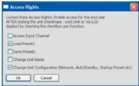
When a speaker system is switched on or when the network connection is interrupted during operation, the speaker system is "locked", providing only a limited range of operating options. To define the operating options available for a locked speaker system:
1) Call up the menu item "Hardware ➤ Configure ➤ Locked Rights". The dialog window "Access Rights" (fig. 10) appears.
2) Select (check mark) the options that are to be available for a locked speaker system:
Access Input Channel:
Accessing input configuration
Load Presets:
Loading presets
Save Presets:
Saving presets
Change Unit Name:
Changing the unit name
Change Unit Configuration:
Changing general settings (network, standby mode, preset at switch-on)
3) Click [OK] to confirm, or click [Cancel] to keep the original settings.
⑩ Locking options
6.6.7 System information
Call up the menu item "Help About" to view information about the speaker system and the network connection as well as about the versions of the speaker system firmware, the interface firmware and the computer program (fig. 11). If a newer firmware version is available in the computer program, the user will be informed accordingly (Update Available); in this case, the firmware should be updated (Chapter 6.3.4). For up-to-date firmware or interface firmware, (OK) is shown behind the respective version numbers.

⑪ System information
Use the menu item "Hardware ➤ Status Detail" to view the errors that may have occurred.
6.6.8 Closing the configuration window
Call up the menu item "File ♦ Quit" to exit the windows for configuring a speaker system. As long as the speaker system is not switched off or not disconnected from the network, the user does not have to re-enter the password when calling up the speaker system again by means of the button [>>] in the list (figs. 2, 3).
To enforce a re-entry of the password, call up the menu item "Hardware ▶Lock Unit". A message is shown informing you that the correct password will then be required to access the settings of the speaker system.
7 Specifications
| Model MEGA-DSP08 MEGA-DSP10 MEGA-DSP12 MEGA-DSP15 | ||||
| Amplifier power (rms power)TrebleBass | 100 W500 W | |||
| Frequency range (-6 dB) | 60-20 000 Hz | 55-20 000 Hz | 45-20 000 Hz | 40-20 000 Hz |
| Max. SPL 116 dB 119 dB 121 dB 123 dB | ||||
| Bass speaker | ∅ 20 cm (8") | ∅ 25 cm (10") | ∅ 30 cm (12") | ∅ 38 cm (15") |
| TweeterrVoice coil | dynamic horn tweeter, ∅25.4 mm (1") | |||
| ∅44 mm | ||||
| Rated input voltageLINEAUXMIC | 1V1V50 mV | |||
| Max. input voltageLINEAUXMIC | 7V5V850 mV | |||
| Input impedanceLINEAUXMIC | 16 kΩ8 kΩ2 kΩ | |||
| Directivity -6 dB (H × V) | 90° × 60° | |||
| Ambient temperature | 0-40°C | |||
| Power supplymax. power consumption | 230V~/50Hz320 VA | 230V~/50Hz360 VA | 230V~/50Hz580 VA | 230V~/50Hz790 VA |
| Dimensions (W × H × D)Weight | 290 × 480 × 313 mm15.5 kg | 320 × 504 × 345 mm18 kg | 350 × 612 × 383 mm19 kg | 416 × 678 × 454 mm25.5 kg |
Subject to technical modification.


- ACTIVE SPEAKER SYSTEM WITH REMOTELY CONTROLLABLE SIGNAL PROCESSOR
- 6.3.4 FIRMWARE UPDATE
- 6.6.5 RUHEMODUS
- 6.6.7 SYSTEMINFORMATIONEN
- BEFORE SWITCHING ON
- CONTENTS
- 1 OPERATING ELEMENTS AND CONNECTIONS
- 2 SAFETY NOTES
- 3 APPLICATIONS
- 4 SETUP AND CONNECTION
- 4.1 TURNING THE TWEETER
- 4.2 CONNECTING A SIGNAL SOURCE
- 4.2.1 SELECTING THE INPUT SENSITIVITY
- 4.3 SIGNAL OUTPUTS
- 4.4 COMPUTER
- 4.5 MAINS CONNECTION
- 5 OPERATION
- 5.1 OPERATION WITHOUT COMPUTER
- CAUTION
- 5.1.1 CALLING UP PRESETS
- 5.1.2 SHOWING SYSTEM INFORMATION
- 5.1.3 DEACTIVATING A LOCK
- 5.1.4 LOCKING UNIT, CHANGING PASSWORD
- 6 REMOTE CONTROL BY MEANS OF A COMPUTER
- 6.1 INSTALLING THE PC SOFTWARE
- 6.2 ESTABLISHING A NETWORK CONNECTION
- 6.3 CONTROL PROGRAM
- INFO
- NAME
- REFERENCE
- ADDRESS
- GROUP
- LAUNCH
- 6.3.1 UNIT GROUPS
- 6.3.1.1 CREATING A NEW GROUP
- 6.3.1.2 DELETING A GROUP
- 6.3.2 CHANGING THE PROGRAM PASSWORD
- 6.3.3 DEMO MODE
- 6.3.5 BGM PLAYER
- 6.3.6 EXITING THE PROGRAM
- 6.4 CONFIGURING THE SPEAKER CAUTION
- 6.4.1 SETTING THE GAIN
- 6.4.2 MUTING THE INPUT
- 6.4.3 SOUND CORRECTION
- 6.4.3.1 FREQUENCY RESPONSE
- 6.4.4 LIMITER
- 6.4.5 SIGNAL DELAY
- 6.4.6 HIGH PASS FILTER (LOW CUT)
- 6.4.7 LINKING INPUTS
- 6.5 MANAGING CONFIGURATIONS
- 6.5.1 LOADING A PRESET
- 6.5.2 SAVING A PRESET
- 6.5.3 SAVING A PRESET ON THE COMPUTER
- 6.5.4 LOADING A PRESET FROM THE COMPUTER
- 6.5.5 SAVING ALL PRESETS ON THE COMPUTER
- 6.5.6 RESTORING A SET OF PRESETS
- 6.5.7 RESTORING FACTORY PRESETS
- 6.6 ADDITIONAL SETTINGS
- 6.6.1 CHANGING THE NAME
- 6.6.2 CHANGING THE PASSWORD
- 6.6.3 CHANGING NETWORK SETTINGS
- 6.6.4 DEFINING PRESET FOR SWITCH-ON
- 6.6.5 STANDBY MODE
- 6.6.6 OPTIONS FOR A LOCKED SPEAKER SYSTEM
- 6.6.7 SYSTEM INFORMATION
- 6.6.8 CLOSING THE CONFIGURATION WINDOW
Brand : Monacor
Model : MEGA-DSP15
Category : Loudspeaker