RA16RF - Car hands-free kit Radical Audio - Free user manual and instructions
Find the device manual for free RA16RF Radical Audio in PDF.


User questions about RA16RF Radical Audio
0 question about this device. Answer the ones you know or ask your own.
Ask a new question about this device
Download the instructions for your Car hands-free kit in PDF format for free! Find your manual RA16RF - Radical Audio and take your electronic device back in hand. On this page are published all the documents necessary for the use of your device. RA16RF by Radical Audio.
USER MANUAL RA16RF Radical Audio
Technical Design Features 4
Installation Considerations 5
Mounting Location 5
Mid/woofer Installation 6
Crossover Wiring 6
Tweeter Installation 7
Fine Tuning of Tweeter Level 8
Fine Tuning of Presence Level 9
Technical Specifications 17
Mounting Dimensions .... 18
Limited Warranty 19
Einleitung ....10
Lieferumfang 10
Technical Specifications 17
Congratulations on your purchase of a Radical Audio Inc. loudspeaker system. Your new component system is comprised of loudspeakers and crossovers, that have been precision engineered to produce the highest quality audio for your vehicle.
This owner's manual provides detailed information on the features, installation and adjustment of the Radical Audio Reference component system. The Radical Audio RA16RF compo is a high performance loudspeaker. To reach optimum performance i.e. best sound reproduction quality, we strongly recommend to have this system installed by a skilled professional installer. This manual assumes that the installer has sufficient in-depth knowledge and experience installing high quality component speaker systems!
Please read this manual carefully! It is suggested to retain this manual and the purchase receipt – as well as the original carton – for possible future use.
If, after reading this manual, you still have questions regarding this product, we strongly recommend to see your nearest authorized Radical Audio Inc. dealer.
PACKAGE CONTENTS
(2) RA16RF (16.5cm) Neodymium Mid/Woofers
(2) RA28RF 28mm Neodymium Soft Dome Tweeters
(2) RA16RF 2-Way Crossovers
(2) MassBelt Steel Rings (13cm or 16.5cm)
(1) Foam Mounting Gasket Set
(1) Driver Mounting Hardware Kit
TECHNICAL DESIGN FEATURES
MID/WOOFER RA16RF
■ 16.5 CM EURO-DIN ALUMINUM DIE-CAST BASKET
■ ADVANCED NEODYMIUM MAGNET MOTOR
■ FARADAY AND KELLOG COPPER SHORTING RINGS
■ CARBON FIBER COMPOUND CONE
■ BACKVENTED BASKET DESIGN
■ NBR NITRILE RUBBER SURROUND
■ YELLOW NOMEX™ SPIDER
■ 36 MM 2-LAYER CCA-WIRE VOICE COIL
■ POLYIMIDE VOICE COIL FORMER
■ GOLD PLATED MOULDED TERMINAL
TWEETER RA28RF
■ 28 MM NEODYMIUM SOFT DOME TWEETER
■ SYNTHETIC SILK DOME DIAPHRAGM
■ NdFeB NEODYMIUM MAGNET MOTOR
■ FARADAY COPPER SHORTING RINGS
■ FERROFLUID COOLED CCAW VOICE COIL
■ ALUMINUM VOICE COIL FORMER
CROSSOVER RA16RF
■ BI-AMPING / BI-WIRING INPUT & OUTPUT
■ TWEETER ATTENUATION BY 4-POSITION JUMPER
■ PRESENCE ATTENUATION BY 2-POSITION JUMPER
■ FR4 GLASS FIBER EPOXY CIRCUIT BOARD
■ HIGH QUALITY INDUCTORS / CAPACITORS
■ GOLD PLATED MOULDED TERMINAL
INSTALLATION CONSIDERATIONS
GENERAL SUGGESTIONS
① Make sure you have enough high quality speaker wire at hand, to reach all the drivers and crossovers from their intended mounting locations! The preferable cross-section is 2x2.5mm². Please note that for quality reasons, speaker wire – e.g. to connect the amplifier to the crossover(s) - must be purchased separately.
② Before you attempt to mount the tweeter(s) or mid/woofer(s) to the doors of your vehicle, check the available mounting depth! Always make sure the speakers or crossovers do not impair the door or window functions.
③ Before you start any wiring work, speaker mounting etc, disconnect the negative main wire lead from the battery! For your own safety...
④ Never run speaker wires over or through sharp edges. Use rubber grommets to protect wires routed through sheet metal.
MOUNTING LOCATION
A solid front stage with good stereo imaging is the most difficult task to achieve in a vehicle! Mostly because the speakers are placed where they will fit easily, as opposed where they can perform best. In most cases, the factory cutouts in the front doors of a vehicle – offer a stable and convenient mounting platform for the mid/woofers. In some cases you will need to purchase car specific plastic adaptors that enable mounting Euro-DIN style mid/woofers to the factory speaker cutouts.
The mounting location for the tweeters does have a profound and direct effect on the stereo imaging of your component system install. Therefore, after mounting the mid/woofers and crossovers – it is recommended to provisionally fix the tweeters to different locations, to be able to choose the mounting spot that offers best possible imaging.
Some mounting tips:
① Place the tweeters where they have a direct and unobstructed path to the listening area. The best visual location may not be the best sounding one!
② Listen to the system with both tweeters connected to the crossovers in phase ( to , to ) AND reversed, before setting tweeter level attenuation.
③ Be sure to use the supplied foam gaskets when mounting the mid/woofers. These gaskets enable an airtight seal between the mid/woofer mounting rim and the speaker mounting hole, which is important to obtain the maximum dynamic range in the upper bass range!
④ The installation of your component set is carried out best, following the sequence below: Removal of Factory Speakers → Wire Routing → Installation of the Mid/Woofers → Mounting of the Crossovers → Mounting of the Tweeters
MID/WOOFER INSTALLATION
You can install the Radical Audio mid/woofers directly to the factory speaker mounting holes, because their Euro-DIN basket bolt hole configuration will fit to a great variety of European and Asian cars.
① Remove the plastic grille (front door) and unscrew the factory installed 16cm fullrange speaker unit.
② Place the Radical Audio Inc. mid/woofer over the mounting hole and see if the existing screw mounting holes and the basket mounting holes align properly. If not, you have to drill new screw mounting holes! Double check if the mounting clearance is sufficient to fit the mid/woofers! Otherwise you risk to impair the window or door function of your vehicle.
③ If the available clearance between the surround of the mid/woofer and the original factory plastic grilles is big enough, you can use the "MassBelt" steel rings supplied with this set. The rings are "sandwiched" between the mounting hole and the mid/woofer unit.
④ Attach the wires to the mid/woofer unit. Double-check for correct speaker polarity! Place the speaker into the mounting hole and screw the speaker into place. Don't forget to use the supplied foam gasket for an airtight seal!
⑤ Remount the factory plastic grilles. While doing this, check for the clearance between surround and backside of the grille. You will need at least 6mm of clearance between surround and the backside – or the surround may hit the grille when the speaker system is pushed hard.
Note → If one of the mid/woofers is wired out of phase (inverted), the resulting sound is very diffuse and the bass is almost nonexistent!
CROSSOVER WIRING
① Wire the crossover unit as shown in the schematic diagram on the next page. Be sure to maintain speaker polarity at the input/output terminals of the crossover!
② Fix the crossover in place with the provided self-tapping screws – and avoid installing the crossovers in locations where they could be exposed to water, excess humidity or other fluids.
Note → It is best to have the crossovers mounted in a location that allows easy access. It may be necessary to re-adjust tweeter attenuation and presence level, after the speaker break-in period.

text_image
RA16RF CROSSOVER MID/WOOFER INPUT TWEETER INPUT MID/WOOFER OUTPUT TWEETER OUTPUT AMP RA28RF TWEETER RA16RF MID/WOOFER Fig.: Crossover WiringTWEETER INSTALLATION
The tweeter units come with an aluminium main housing and a front rim that features three mounting holes. After you have determined the best sounding tweeter location, you can cut two holes with 48.5mm diameter, using a hole-saw attachment for your power drill.
Insert the tweeter wire into the hole you have just cut, attach the tweeter extension wire on the back and fix the tweeters in place using the cross bar, provided by the mounting hardware set.
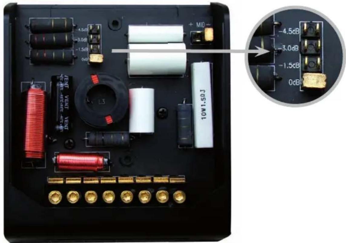
FINE TUNING OF TWEETER LEVEL
Fig.: Jumperposition Tweeter Level
text_image
MID -4.5dB -3.0dB -1.5dB 0dB VENT VENT VENT 10W1.50J -4.5dB -3.0dB -1.5dB 0dBATTENTION: Before you start to fine tune tweeter level and presence level, be sure the following steps have been completed:
→ All wiring work has been done (loudspeakers, crossovers, amplifier are wired etc).
→ Highpass and lowpass crossover frequency adjustments on the amplifier have been carried out.
→ Input gain level adjustment of satellite- and subwoofer channels (if applicable) are set
→ All tone controls – including the loudness function – have been reset to their neutral / zero position.
① Four different tweeter attenuation levels can be selected, to compensate for different tweeter mounting locations and – of course – to suit personal preferences.
② Slide back the transparent cover of the crossover unit and set the preferred attenuation level by adjusting the jumper on the circuit board.
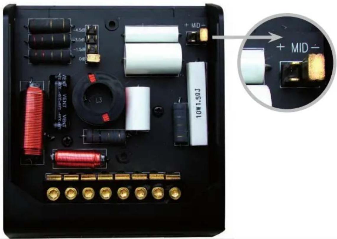
FINE TUNING OF PRESENCE LEVEL
Fig.: Jumperposition Presence Level
text_image
-4.5dB -3.0dB -1.5dB 0dB + MID - 10W1.50J + MID -① The presence level (3 – 5kHz) can be set by adjusting the jumper to “⊕” or “⊖” depending on the tweeter mounting location and personal preferences.
② Slide back the transparent cover of the crossover unit and set the preferred attenuation level by adjusting the "presence" jumper on the circuit board. Set the jumper to "⊕", if your tweeters are mounted relatively far away from the mid/woofers (like A-pillars or window triangle). Set the presence jumper to "⊖" when the tweeters are mounted in close vicinity of the mid/woofers.
CAUTION: Both attenuation jumpers – for tweeter attenuation and presence adjustment – must always be set to identical positions! The final tweeter and presence level adjustments should be carried out best, after the installation is complete with all the additional components being installed, like for example subwoofer, amplifier(s) etc.
EINLEITUNG
*Via 12dB/oct. highpass filter network @ 2700 Hz
CROSSOVER MODEL RA16.2RF
| Crossover Type | 2-Way |
| Crossover Frequency | 2800Hz |
| Electrical Crossover Slopes | 12dB/oct. tweeter highpass |
| 18dB/oct. mid/woofer lowpass | |
| Tweeter Attenuation | 0dB/+1.5dB/+3dB/+4.5dB |
| Presence Attenuation | « + » or « - » |
- Technical construction and specifications subject to changes without notice! -

If at any time in the future you should need to dispose this product please note that waste electrical products should not be disposed of with household waste. Please recycle where facilities exist. Check with your Local Authority or retailer for recycling advice. (Waste Electrical and Electronic Equipment Directive)
Radical Audio warrants this RA16RF component speaker system and it's parts to be free of defects in materials and workmanship for TWO YEARS from the date of purchase at retail, contingent upon being properly installed and approved by an authorized Radical Audio Inc. dealer.
Radical Audio will at its own discretion repair or replace any mechanically defective speaker unit or crossover during this warranty period.
Should your Radical Audio component system – or parts of it – require warranty service, please return it to the retailer from whom it was purchased. Please do not send any product to Radical Audio directly, as this could result in delays of the warranty return procedure. If you encounter difficulties in finding an authorized Radical Audio service center, details are available from the national distributor in the country of purchase, or on the homepage www.radical-audio.com.
Abuse of this component speaker system due to excessive amplifier power, improper installation, amplifier clipping, physical damage, or unauthorized modification of the speaker units and x-overs is not covered under warranty.
natural_image
Abstract geometric logo design with white and green stylized letters (no text or symbols)AUDIO
RADICAL AUDIO INC.
15584 E. Gale Avenue
Hacienda Heights
CA 91745, USA