GWH12 - Air-conditioner AIRLUX - Free user manual and instructions
Find the device manual for free GWH12 AIRLUX in PDF.

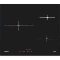
| Product Type | Split Air Conditioner (Wall-mounted) |
| Model | GWH12 |
| Brand | Airlux |
| Power Supply | 230V ~ 50Hz (estimated from wiring diagrams) |
| Cooling Capacity | 12,000 BTU/h (typical for GWH12 model) |
| Heating Capacity | 12,000 BTU/h (heat pump models) |
| Operation Modes | Auto, Cool, Dry, Fan, Heat (heat pump) |
| Fan Speeds | Auto, Low, Medium, High |
| Remote Control | Infrared LCD remote with timer, swing, turbo, sleep, X-FAN, I FEEL |
| Timer Functions | ON and OFF timer with 24-hour setting |
| Air Filter | Washable mesh filter (recommended cleaning every 3 months) |
| Refrigerant | R32 or R410A (not specified in manual, typical for this capacity) |
| Connection Pipe Length | Max 10m |
| Height Difference (indoor/outdoor) | Max 5m |
| Safety Features | Overload protection, automatic defrost, child lock, earth leakage protection |
| Installation | Professional installation required; wall-mounted indoor unit, outdoor unit on bracket |
| Dimensions (Indoor Unit) | Approx. 800 x 290 x 200 mm (estimated from typical 12k BTU units) |
| Dimensions (Outdoor Unit) | Approx. 800 x 550 x 300 mm (estimated) |
| Weight (Indoor Unit) | Approx. 10 kg (typical) |
| Weight (Outdoor Unit) | Approx. 30 kg (typical) |
| Warranty | Standard manufacturer warranty (check with dealer) |
Frequently Asked Questions - GWH12 AIRLUX
User questions about GWH12 AIRLUX
0 question about this device. Answer the ones you know or ask your own.
Ask a new question about this device
Download the instructions for your Air-conditioner in PDF format for free! Find your manual GWH12 - AIRLUX and take your electronic device back in hand. On this page are published all the documents necessary for the use of your device. GWH12 by AIRLUX.
USER MANUAL GWH12 AIRLUX
Thank you for selecting AIRLUX air conditioners. Please read this manual carefully before operation and keep it for further reference.
66129908792

CONTENTS
Operation and maintenance
■ 1 Safety Precautions ....
■ Name of parts 4
Operation of Remote Controller 5
■ ...Emergency.operation.... 11
■ Clean and care 12
- ...Troubleshooting.... 14
Installation service
■ Notices for installation.... 17
■ Installation Drawing 20
■ Installation of Indoor unit 21
■ Installation of Outdoor unit 24
■ Check after Installation and 25peration Test ……
■ Circuit diagram26
The figures in this manual may be different with the material objects, please refer to the material objects for reference.

Never attempt.

Be sure to follow this instruction
Do not dispose this product as unsorted municipal waste.
Collection of such waste separately for special treatment is necessary.

Safety Precautions
| Please read the following notices before operation. | ||
| WARNING | ||
★ If there's abnormal phenomenon (like smell of burning), please cut off the power immediately and then contact with AIRLUX authorized maintenance center.  If this abnormal status is kept on, air conditioner may be damaged or even cause electric shock or fire. If this abnormal status is kept on, air conditioner may be damaged or even cause electric shock or fire. | ★ Do not operate the air conditioner with wet hands.  Otherwise, it may cause electric shock. Otherwise, it may cause electric shock. | ★ Do not cut off or damage the power cord or signal control wire. If the power cord or signal control wire of air conditioner is damaged, please replace it by the professional with specified power cord. |
★ The special circuit must be adopted for power supply to avoid fire.  Do not use octopus multipurpose socket or mobile wiring board for wire connection. Do not use octopus multipurpose socket or mobile wiring board for wire connection. | ★ Please cut off the power supply when the air conditioner won't be used for an extended period of time. 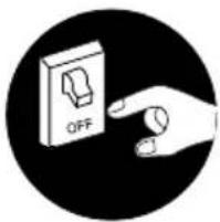 Otherwise, accumulated dust may cause overheating, fire and other accidents. Otherwise, accumulated dust may cause overheating, fire and other accidents. | ★ Do not damage the power cord or use unspecified power cord.  Otherwise, it may cause fire due to overheating of power cord. Otherwise, it may cause fire due to overheating of power cord. |
★ Before cleaning the air conditioner, please cut off the power.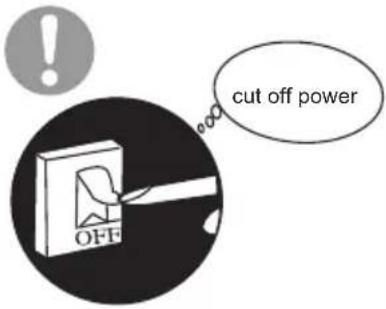 Otherwise, it will cause electric shock or injury. Otherwise, it will cause electric shock or injury. | ★ Power supply should adopt the special circuit with the protection of air switch and the capacity must be sufficient. Pease do not turn on or turn off the air conditioner frequently. JY-type connection is adopted for the power supply of this air conditioner. If the power cord is damaged, it must be replaced by the manufacturer, maintenance center or a similarly qualified person to avoid a hazard. J | ★ When the voltage is too high, electric elements can be damaged easily; if the voltage is too low, the compressor will vibrate fiercely, which may damage the cooling system or compressor, and electric components can't operate. |

Safety Precautions
 ★ Always ensure effective earthing. ★ Always ensure effective earthing.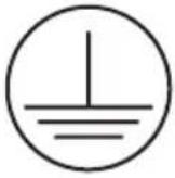 No earthing may cause electric shock. No earthing may cause electric shock. | ★ For safety, be sure to turn off the circuit beaker before performing any maintenance or cleaning or when the product is not used for an extended period of time. 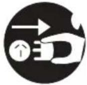 Accumulated dust may cause fire or electric shock. Accumulated dust may cause fire or electric shock. | ★ Select the most appropriate temperature.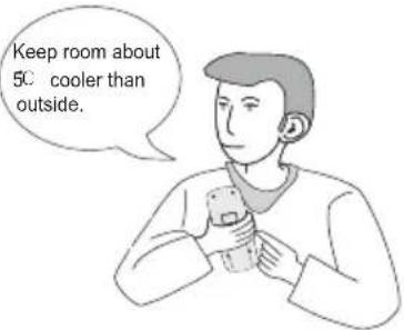 It can save electric energy. It can save electric energy. |
★ Do not keep windows and doors open for a long time during operation.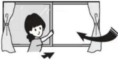 It will result in insufficient performance. It will result in insufficient performance. | ★ Do not block the air inlet or outlet.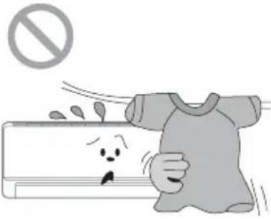 It will result in insufficient performance and cause malfunctions. It will result in insufficient performance and cause malfunctions. | ★ Keep combustible materials at least 1m away from the units .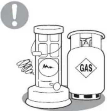 .noiso .noiso |
★ Install the outdoor unit firmly enough.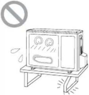 It may cause falling of the unit and injury to the person. It may cause falling of the unit and injury to the person. | ★ Do not step on the top of the outdoor unit or place heavy things on it.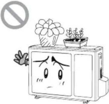 It may cause damage or injury . It may cause damage or injury . | ★ Do not attempt to repair the air conditioner by yourself.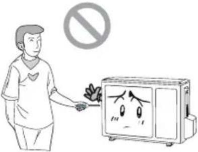 Incorrect repairs may cause electric shock or fire. Please contact the local authorised service center. Incorrect repairs may cause electric shock or fire. Please contact the local authorised service center. |

Safety Precautions
★ Do not cut off or damage the power cords or control cords. If they are damaged, please contact the dealer or qualified service personnel | ★ To change the airflow direction, adjust the vertical and horizontal air flow direction by using the remote controller. Vertical Louver Horizontal Louver Vertical Louver Horizontal Louver |
★ Do not insert your hands or objects into the air inlet or outlet.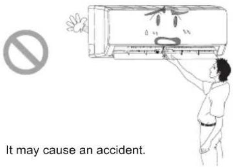 | ★ Do not expose animals or plants directly to the air flow.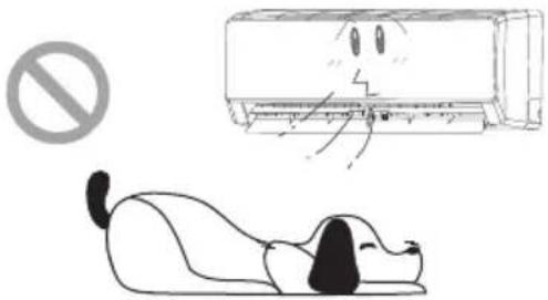 It may have a detrimental effect on them. It may have a detrimental effect on them. |
★ Do not expose yourself to cold air directly for a long time.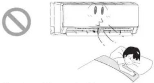 It's not good for your health. It's not good for your health. | ★ Do not use the unit for any other purpose, such as preserving food or drying clothes.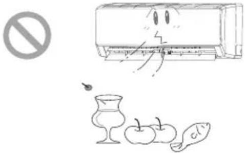 |
★ Do not splash water on the air conditioner.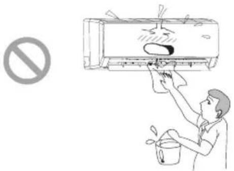 It may cause electric shock or malfunction. It may cause electric shock or malfunction. | ★ Do not place a burner near the air conditioner.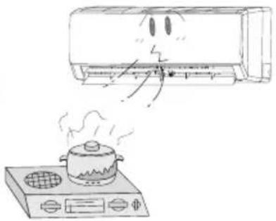 It will cause CO toxicosis due to incomplete burning. It will cause CO toxicosis due to incomplete burning. |

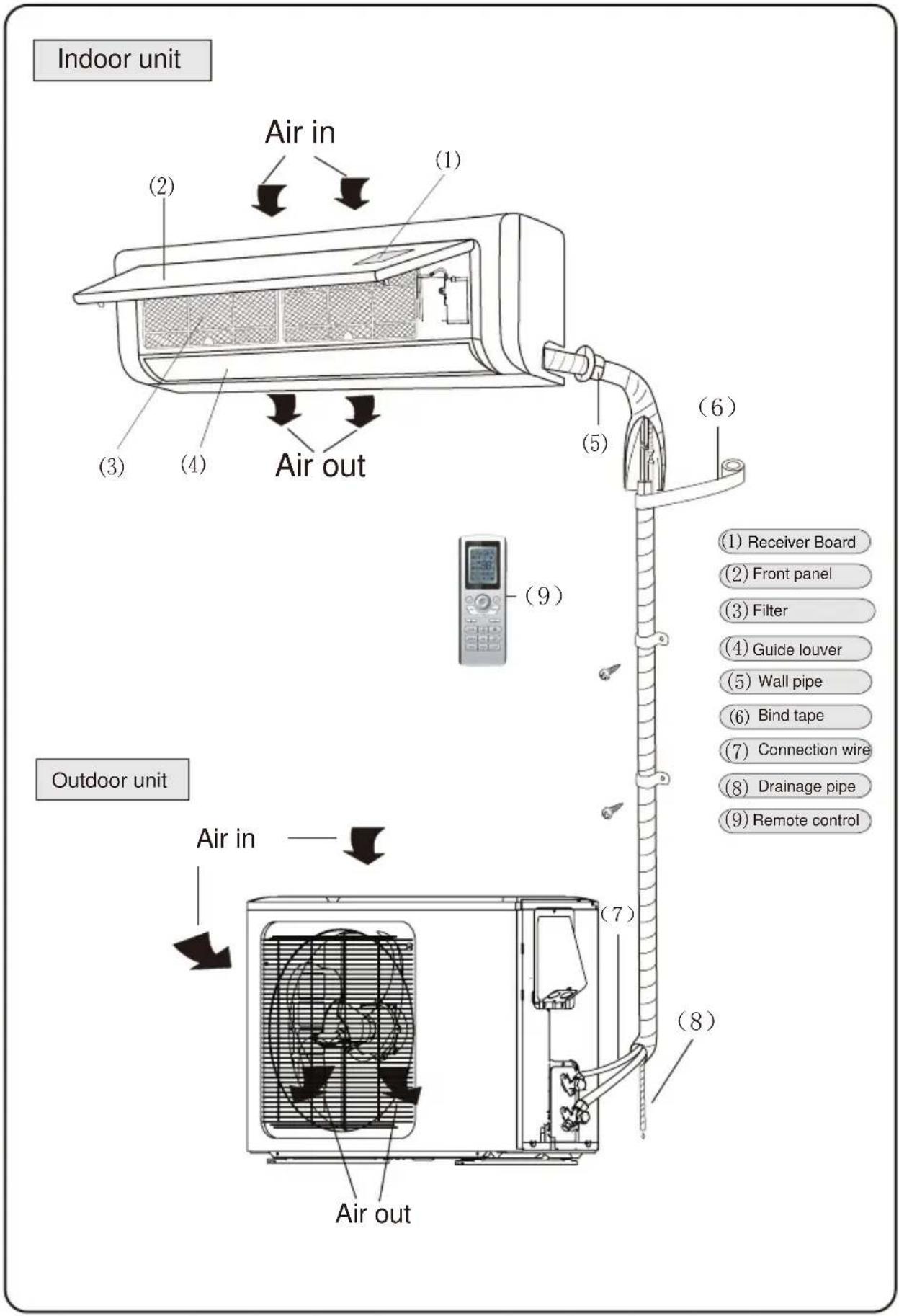
Names of Parts

Operation of Remote Controller
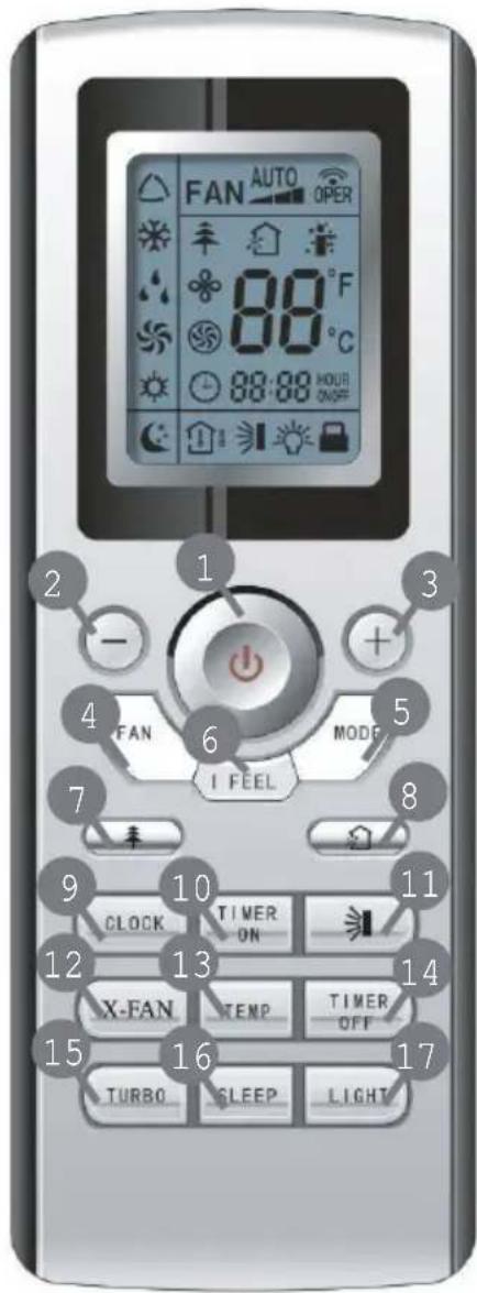
1 ON/OFF
Press it to start or stop operation.
2 - : Press it to decrease temperature setting.
3 + : Press it to increase temperature setting.
4 FAN
Press it to set fan speed.
5 MODE
Press it to select operation mode (AUTO/COOL/DRY/FAN/HEAT).
6 I FEEL
7
Press it to set HEALTH function
8
Press it to set AIR function.
9 CLOCK
Press it set clock.
10 TIMER ON
Press it to set auto-on timer.
11
Press it set swing angle.
12 X-FAN
13 TEMP
14 TIMER OFF
Press it to set auto-off timer
15 TURBO
16 SLEEP
17 LIGHT
Press it to turn on/off the light.

Operation of Remote Controller
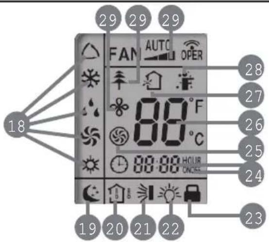
18 MODE icon:
If MODE button is pressed, current operation mode icon
△(AUTO), ✕ (COOL),
(DRY), ⚙ (FAN) or ⚙ (HEAT only for heat pump models) will show.
19 SLEEP icon :
is displayed by pressing the SLEEP button. Press this button again to clear the display.
20 TEMP icon:
Pressing TEMP button,
(set temperature), (indoor ambient temperature)
(outdoor ambient temperature) and blank is displayed circularly.
21 Up & down swing icon:
is displayed when pressing the up & down swing button.
Press this button again to clear the display.
22 LIGHT icon:
is displayed by pressing the LIGHT button. Press LIGHT button again to clear the display.
23 LOCK icon:
is displayed by pressing "+" and "-" buttons simultaneously. Press them again to clear the display.
24 SET TIME display:
After pressing TIMER button, ON or OFF will blink. This area will show the set time.
25 TURBO icon:
is displayed when pressing the
nottub siht ss
again to clear the display.
26 DIGITAL display:
This area will show the set temperature. In SAVE mode, "SE" will be displayed. During defrosting operation, "H1" will be displayed.

Operation of Remote Controller
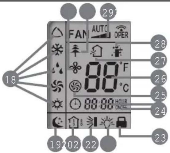
27 AIR icon:
is displayed when pressing the AIR button. Press this button again to clear the display.
30 HEALTH icon:
is displayed when pressing the HEALTH button. Press this button again to clear the display.
28 I FEEL icon:
is displayed when pressing the I FEEL button. Press this button again to clear the display.
31 X-FAN icon:
is displayed when pressing the X-FAN button. Press this button again to clear the display.
29 FAN SPEED display:
Press FAN button to select the desired fan speed setting (AUTO-Low-Med-High). Your selection will be displayed in the LCD windows except the AUTO fan speed.

Operation of Remote Controller
Remote Controller Description
1 ON/OFF :
Press this button to turn on the unit .Press this button again to turn off the unit.
2 —:
Press this button to decrease set temperature. Hold it down for above 2 seconds to rapidly decrease set temperature. In AUTO mode, set temperature is not adjustable.
3 + :
Press this button to increase set temperature. Hold it down for above 2 seconds to rapidly increase set temperature. In AUTO mode, set temperature is not adjustable.
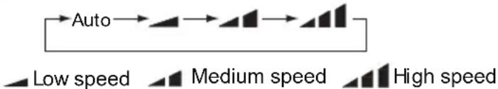
4 FAN :
This button is used for setting Fan Speed in the sequence that goes from AUTO, , to , then back to Auto.
flowchart
graph LR
    A["Auto"] --> B["Stage 1"]
    B --> C["Stage 2"]
    C --> D["Stage 3"]
    D --> E["Stage 4"]
    style A fill:#f9f,stroke:#333
    style E fill:#f9f,stroke:#333
    note1["Low speed"] -.-> A
    note2["Medium speed"] -.-> B
    note3["High speed"] -.-> C
    classDef stage fill:#f9f,stroke:#333;
    class A,B,C,D,E stage;
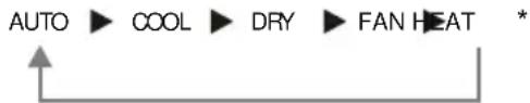
5 MODE :
Each time you press this button, a mode is selected in a sequence that goes from AUTO, COOL,DRY, FAN,and HEAT *,as the following:
flowchart
graph LR
    A["AUTO"] --> B["COOL"]
    B --> C["DRY"]
    C --> D["FAN HEAT"]
    D --> E["*"]
*Note: Only for models with heating function.
After energization, AUTO mode is defaulted. In AUTO mode, the set temperature will not be displayed on the LCD, and the unit will automatically select the suitable operation mode in accordance with the room temperature to make indoor room comfortable.
6 I FEEL:
Press this button to turn on I FEEL function. The unit automatically adjust temperature according to the sensed temperature. Press this button again to cancel I FEEL function.
7
Press this button to set HEALTH function ON or OFFAfter the unit is turned on, it defaults to HEALTH function ON. Some models don't have this function.
8
Press this button to select AIR function ON or OFF. There is no this function for this unit.
9 CLOCK :
Pressing CLOCK button, ⏻ blinks. Within 5 seconds, pressing + or - button adjusts the present time. Holding down either button above 2 seconds increases or decreases the time by 1 minute every 0.5 second and then by 10 minutes every 0.5 second. During blinking after setting, press CLOCK button again to confirm the setting, and then ⏻ will be constantly displayed.

Operation of Remote Controller
10 TIMER ON :
Press this button to initiate the auto-ON timer. To cancel the auto-timer program, simply press this button again.
After pressing this button, ⏻ disappears and "ON "blinks. 00:00 is displayed for ON time setting. Within 5 seconds, press + or - button to adjust the time value. Every press of either button changes the time setting by 1 minute. Holding down either button rapidly changes the time setting by 1 minute and then 10 minutes. Within 5 seconds after setting, press TIMER ON button to confirm.
11
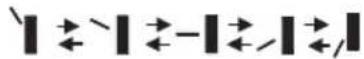
Press this button to set up & down swing angle, which circularly changes as below:
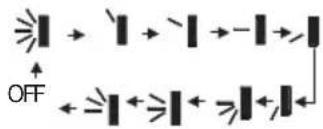
This remote controller is universal. If any command ≥slant I , ≥slant I or ≥slant I is sent out, the unit will carry out the command as ≥slant I
indicates the guide louver swings as:
12 X-FAN:
Pressing X-FAN button in COOL or DRY mode, the icon is displayed and the indoor fan will continue operation for 10 min utes in order to dry the indoor unit even though you have turned off the unit.
After energization, X-FAN OFF is defaulted. X-FAN is not available in AUTO, FAN or HEAT mode.
13 TEMP:
Press this button, could select displaying the indoor setting temperature or indoor ambient temperature. When the indoor unit firstly power on it will display the setting temperature, if the temperature's displaying status is changed from other status to ", displays the ambient temperature, 5s later or within 5s, it receives other remote control signal that will return to display the setting temperature. if the users haven't set up the temperature displaying status, that will display the setting temperature. (This function is not applicable for some models).
14 TIMER OFF :
Press this button to initiate the auto-off timer. To cancel the auto-timer program, simply press the button again. TIMER OFF setting is the same as TIMER ON.
15 TURBO:
Press this button to activate / deactivate the Turbo function which enables the unit to reach the preset temperature in the shortest time. In COOL mode, the unit will blow strong cooling air at super high fan speed. In HEAT mode, the unit will blow strong heating air at super high fan speed. (This function is not applicable for some models).

Operation of Remote Controller
16
SLEEP:
Press this button to go into the SLEEP operation mode. Press it again to cancel this function. This function is available in COOL, HEAT (Only for models with heating function) or DRY mode to maintain the most comfortable temperature for you.
17
LIGHT:
Press LIGHT button to turn on the display's light and press this button again to turn off the display's light. If the light is turned on, 🔒 is displayed. If the light is tuned off, 🔒 disappears.
18
Combination of "+" and "-" buttons: About lock
Press "+ " and "-" buttons simultaneously to lock or unlock the keypad. If the remote controller is locked, 🔔 is displayed. In this case, pressing any button, 🔔 blinks three times.
19
Combination of "MODE" and "-" buttons: About switch between Fahrenheit and Centigrade at unit OFF, press "MODE" and "-" buttons simultaneously to switch between ^ and ^ .
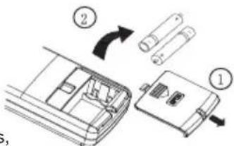
Replacement of Batteries
- Remove the battery cover plate from the rear of the remote controller. (As shown in the figure)
- Take out the old batteries.
- Insert two new AAA1.5V dry batteries, and pay attention to the polarity.
- Reinstall the battery cover plate.

Notes:
- When replacing the batteries, do not use old or different types of batteries, otherwise, it may cause malfunction.
- If the remote controller will not be used for a long time, please remove batteries to prevent batteries from leaking.
● The operation should be performed in its receiving range. - It should be kept 1m away from the TV set or stereo sound sets.
- If the remote controller does not operate normally, please take the batteries out and reinsert them after 30 seconds. If it still can't operate properly, replace the batteries.
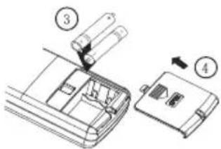
Sketch map for replacing batteries

Emergency Operation
Emergency Operation
When the remote controller is lost or damaged, please use the manual switch on the main unit. In that case, the unit will operate in AUTO mode and the temperature setting or fan speed can not be changed. The manual switch can be operated as below:
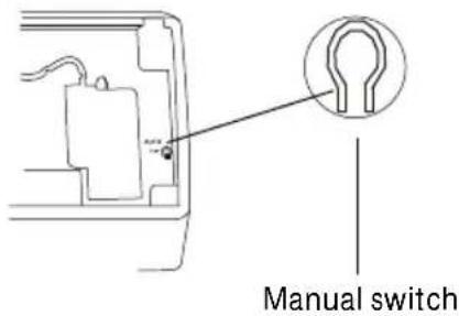
- Turn on the unit: Press AUTO/STOP button to enter AUTO mode.
The microprocessor will select the mode (COOL, HEAT, FAN) automatically according to the room temperature for reaching comfortable effect. - Turn off the unit: Press the AUTO/STOP button to switch off the unit.
- The operation mode is shown in the following table.
| Mode | Model | Temperature | ure setting | Airflow rate | |
| AUTO | COOLING | 25 ( | COOL,FAN) | AUTO | |
| AUTO | HEAT | PUMP | 25 ( | COOL,FAN) AUTO | |
| AUTO | HEAT | PUMP 20 | ( HEAT) | AUTO |
- This switch is to be applied when the remote controller is missing.

Clean and care

CAUTION
- Turn power off and pull out the power plug before cleaning air conditioner. Or it may cause electric shock.
- Never sprinkle water on the indoor unit and the outdoor unit for cleaning because it can cause an electric shock.
Volatile liquid (e.g. thinner or gasoline) will damage the air conditioner. (So wipe the units with a dry soft cloth, or a cloth slightly moistened with water or cleanser.)
Clean the front panel(make sure to take it off before cleaning)
① Take off the front panel
Along the direction of arrows to lift the front panel up, meanwhile to hold both slots of the front panel and take it out forcibly and then can take it off.
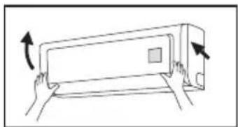
natural_image
Illustration of hands holding a rectangular appliance with an arrow indicating rotation (no text or symbols)② Washing
Washing□□Clean with a soft brush, water and neutral detergent and then dry it.(Note: Before cleaning the unit, please take down the displayer box firstly, then to wash the panel, if the unit has displayer on the front panel. Never use the water above 45 °C to wash the panel, or it could cause deformation or discoloration.)
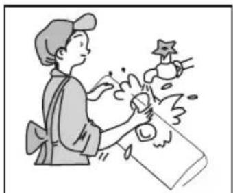
natural_image
Illustration of a person washing clothes with a star-shaped object nearby (no text or symbols)③ Install front panel
Place two supporters of the front panel into the slots, along the direction of arrows to cover and clasp the front panel. As show in right figure.
natural_image
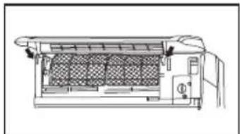
Technical line drawing of a mechanical device with internal components (no text or symbols)Cleaning the air filters (Recommended once every three
Note: If dust is much more around the air conditioner, the air filters should be cleaned many times. After taking off the filter, don't touch the fin of indoor unit, in order to avoid hurt your fingers.

Clean and care
① Take down the air filter
At the slot of surface panel to open an angle, pull the air filter downward and take it out.
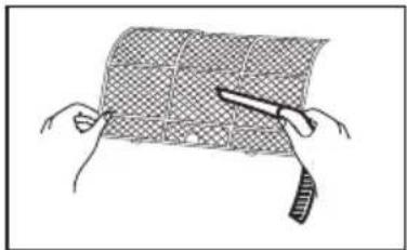
② Cleaning
To clean the dust adhering to the filters, you can either use a vacuum cleaner, or wash them with warm water (the water with the neutral detergent should below 45°C). When the filters are very dirty (such as oil stain), and dry it in the shade.
NOTE: Never use water above 45^ C to wash, or it can cause deformation or discoloration. Never partch it by fire, or can cause a fire or deformation.
natural_image
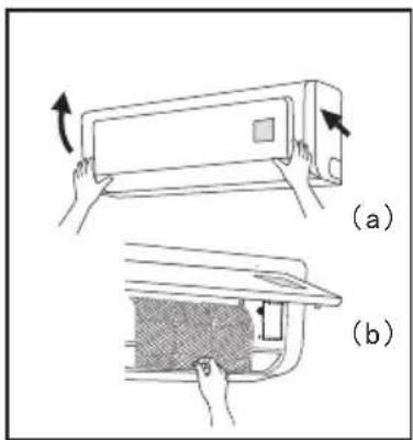
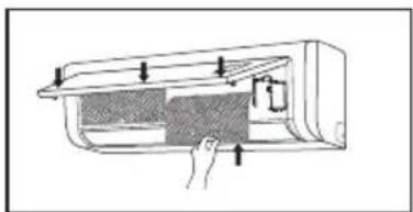
Illustration of hands holding a grid-patterned object with a tool, no text or symbols present③ Reinsert the filters
Reinsert the filters along with the arrow head, then cover the surface panel and clasp it.
natural_image
Diagram of a hand inserting a component into a device (no text or symbols visible)Check before use
① Be sure that nothing obstructs the air outlet and intake vents.
② Check that whether ground wire is properly connected or not.
③ Check that whether the batteries of air conditioner are changed or not.
④ Check that whether the installation stand of the outdoor unit is damaged or not. If damaged, please contact the dealer.
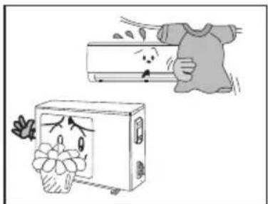
natural_image
Illustration of a washing machine with a cartoon face and a hand holding a cloth (no text or symbols)Maintain after use
① Turn main power off.
② Clean the filter and indoor and outdoor units' bodies.
③ Repaint the rubiginous place on the outdoor unit to prevent it from spreading.

Troubleshooting

CAUTION
The air conditioner is not expected to be serviced by users. Incorrect repair may cause electric shock or fire, so please contact an authorized service center for professional service. The following checks prior to contact may save your time and money.
| Phenomenon | Troubleshooting |
The unit does not operate: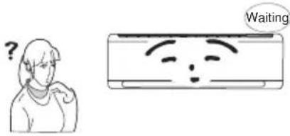 | · The unit does not operate if it is turned on immediately after being turned off. This is to protect the unit. You are expected to wait for about 3 minutes. |
Odours are emitted: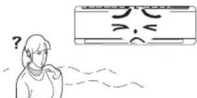 | · Some odours may be emitted from the indoor unit. This is the result of room smells (such as furniture, tobacco, ect.) which have been taken into the air conditioner.· Consult authorized service center for cleaning if the odours still exist. |
"Water flowing" noise: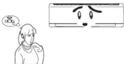 | · The swishing noise like water flowing is the sound of refrigerant flowing inside the unit. |
Mist is emitted in COOL mode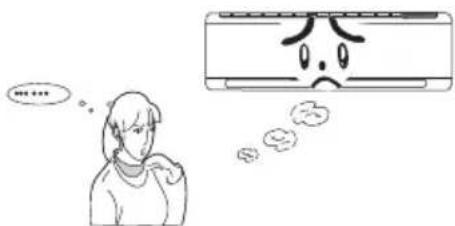 | · During cooling operation, a thin mist may be seen emitted from the indoor unit due to high room temperature and humidity. After a period of time, the mist will disappear with the decrease of room temperature and humidity. |
Cracking noise: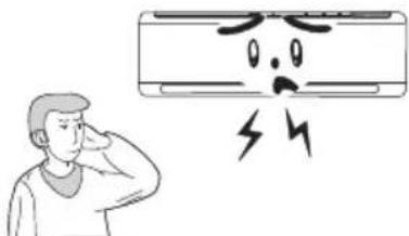 | · This is the sound of friction caused by expans and/or contraction of panel or other parts due to the change of temperature. |

Troubleshooting
| Phenomenon | Troubleshooting |
The unit can not be started up: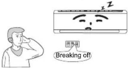 | Is the power cut off?Is the power plug loose? (If applicable)Is the circuit protection device tripped off?Is voltage higher or lower?(Tested by professionals)Is the TIMER correctly used? |
Cooling/Heating effect is poor: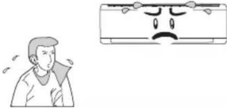 | Is temperature setting appropriate?Is the inlet or outlet blocked?Is the filter dirty?Is the window or the door open?Is low fan speed set?Are there heat sources in the room? |
Remote controller is not available: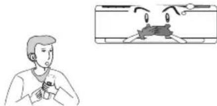 | Check if there is magnetic or electrical interference near the unit that may affecting operation of the controller. In this case, pull the plug out and reinsert it.Is the remote controller within its operating range or obstructed? Check the condition of the batteries and replace them if necessary.Check if the remote controller is damaged. |
| Water leakage of indoor unit : | The humidity is high.Condensate overflows.Drain hose is loose. |
| Water leakage of outdoor unit : | During cooling operation, condensate is generated around the pipes and connection joints.During defrosting operation, the thaw water flows out.During heating operation, the water on the heat exchanger drips out. |
| Noise from indoor unit. The noise emitted when the fan or compressor relay is switching on or off.When the defrosting operation is started or stopped, there is a sound of refrigerant flowing in the reverse direction. | |

Troubleshooting
| Phenomenon | Troubleshooting |
| Indoor unit can not blow air: | In HEAT mode, when the temperature of indoor heat exchanger is very low, air flow is stopped in order to prevent cold air. (Within 2minutes)In HEAT mode, when the outdoor temperature is low or humidity is high, frost will be formed on the outdoor heat exchanger. The unit will defrost automatically and indoor unit will stop blowing air for 3-12minutes.During defrosting operation, water or vapour may be emitted.In DRY mode, the indoor fan will stop blowing air for 3-12 minutes in order to avoid condensate being vaporised again. |
| Moisture on air outlet : | If the unit operates at high humidity for a long time, moisture will be generated on the air outlet grill and then drip off. |
| C5: Malfunction of connector jumper: | Check if the connector jumper contacts properly. If the PCB is to be replaced, please take off the old for the new PCB. |
| F1: Malfunction of indoor ambient temperature sensor | Check if indoor room temperature sensor is connected properly. |
| F2: Malfunction of evaporator temperature sensor | Check if the evaporator temperature is connected properly. |
| H1: Defrosting It is normal. | ● |
 If any one of the following situations occurs, immediately stop all operations, cut off the power supply, and contact the authorized personnel If any one of the following situations occurs, immediately stop all operations, cut off the power supply, and contact the authorized personnel | |
| There is harsh sound during operation.Strong odours are emitted during operation.Water is leaking from the unit.The air switch or protection switch often trips.Water or other liquid is splashed into the unit.Power cord and power plug is overheating. | |

Notices for Installation

Caution
-
The unit should be installed only by authorized service center according to local or government regulations and in compliance with this manual.
-
Before installing, please contact with local authorized maintenance center. If the unit is not installed by the authorized service center, the malfunction may not be solved due to incovenient contact between the user and the service personnel.
-
When removing the unit to the other place, please firstly contact with the local authorized service center.
-
Warning: Before obtaining access to terminals, all supply circuits must be disconnected.
-
For appliances with type Y attachment, the instructions shall contain the substance of the following. If the supply cord is damaged, it must be replaced by the manufacturer, its service agent or similarly qualified persons in order to avoid a hazard.
-
The appliance must be positioned so that the plug is accessible.
-
The temperature of refrigerant line will be high; please keep the interconnection cable away from the copper tube.
-
The instructions shall state the substance of the following:
This appliance is not intended for use by persons(including children)with reduced physical, sensory or mental capabilities, or lack of experience and knowledge, unless they have been given supervision or instruction concerning use of the appliance by a person responsible for their safety.
Children should be supervised to ensure that they do not play with the appliance.
Installation Site Instructions
Proper installation site is vital for correct and efficient operation of the unit. Avoid the following sites where:
• strong heat sources, vapours, flammable gas or volatile liquids are emitted.
- high-frequency electro-magnetic waves are generated by radio equipment, welders and medical equipment.
- salt-laden air prevails (such as close to coastal areas).
- the air is contaminated with industrial vapours and oils.
- the air contains sulphures gas such as in hot spring zones.
• corrosion or poor air quality exists.

Notices for Installation
Earthing Requirements
- Air conditioner is type I electric appliance. Please ensure that the unit is reliably earthed.
- The yellow-green wire in air conditioner is the earthing wire which can not be used for other purposes. Improper earthing may cause electric shock.
- The earth resistance should accord to the national criterion.
- The power must have reliable earthing terminal. Please do not connect the earthing wire with the following:
① Water pipe
②Gas pipe
③ Contamination pipe
④ Other place that professional personnel consider is unreliable
- The model and rated values of fuses should accord with the silk print on fuse cover or related PCB.

Notices for Installation
Installation Site of Indoor Unit
- The air inlet and outlet should be away from the obstructions. Ensure the air can be blown through the whole room.
- Select a site where the condensate can be easily drained out, and where it is easily connected to outdoor unit.
- Select a place where it is out of reach of children.
- Select a place where the wall is strong enough to withstand the full weight and vibration of the unit.
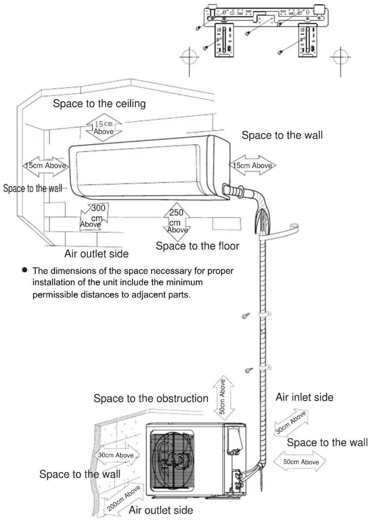
- Be sure to leave enough space to allow access for routine maintenance. The installation site should be 250cm or more above the floor.
- Select a place about 1m or more away from TV set or any other electric appliance.
- Select a place where the filter can be easily taken out.
- Make sure that the indoor unit is installed in accordance with installation dimension instructions.
- Do not use the unit in the laundry or by swimming pool etc.
Installation Site of Outdoor Unit
- Select a site where noise and outflow air emitted by the unit will not annoy neighbors.
- Select a site where there is sufficient ventilation.
- Select a site where there is no obstruction blocking the inlet and outlet.
- The site should be able to withstand the full weight and vibration.
- Select a dry place, but do not expose the unit to direct sunlight or strong wind.
- Make sure that the outdoor unit is installed in accordance with the installation instructions, and is convenient for maintenance and repair.
- The height difference between indoor and outdoor units is within 5 m, and the length of the connecting tubing does not exceed 10 m.
- Select a place where it is out of reach of children.
- Select a place where the unit does not have negative impact on pedestrians or on the city.
Safety Precautions for Electric Appliances
- A dedicated power supply circuit should be used in accordance with local electrical safety regulations.
- Don't drag the power cord with excessive force.
- The unit should be reliably earthed and connected to an exclusive earth device by the professionals.
- The air switch must have the functions of magnetic tripping and heat tripping to prevent short circuit and overload.
- The minimum distance between the unit and combustive surface is 1.5m.
- The appliance shall be installed in accordance with national wiring regulations.
- An all-pole disconnection switch with a contact separation of at least 3mm in all poles should be connected in fixed wiring.
Note:
- Make sure the live wire, neutral wire and earth wire in the family power socket are properly connected. There should be reliable circuit in the diagram.
- Inadequate or incorrect electrical connections may cause electric shock or fire.

Installation Drawing
Installation dimension diagram

Installation of Indoor Unit
Installation of Mounting Plate
- Mounting plate should be installed horizontally. As the water tray's outlet for the indoor unit is two-way type, during installation, the indoor unit should slightly slant to water tray's outlet for smooth drainage of condensate.
- Fix the mounting plate on the wall with screws.
- Be sure that the mounting plate has been fixed firmly enough to withstand about 60 kg. Meanwhile, the weight should be evenly shared by each screw.
12K UNIT:
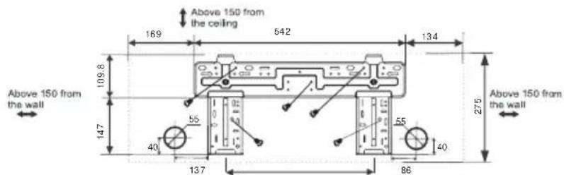
Fig.5
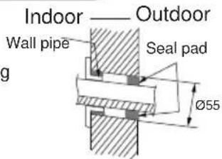
Drill Piping Hole
- Slant the piping hole ( 55) on the wall slightly downward to the outdoor side.
- Insert the piping-hole sleeve into the hole to prevent the connection piping and wiring from being damaged when passing through the hole.
Installation of Drain Hose
-
Connect the drain hose to the outlet pipe of the indoor unit. Bind the joint with rubber belt.
-
Put the drain hose into insulating tube.
-
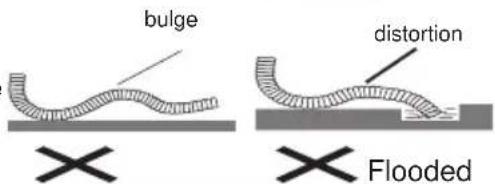
Wrap the insulating tube with wide rubber belt to prevent the shift of insulating tube. Slant the drain hose downward slightly for smooth drainage of condensate.
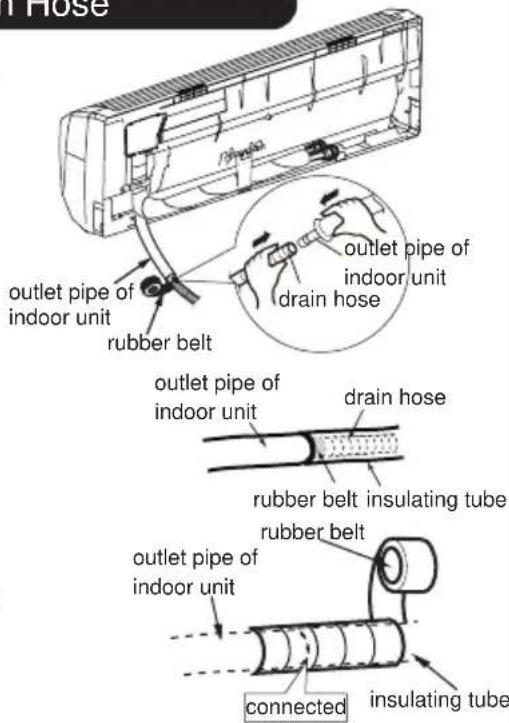
Note: The insulating tube should be connected reliably with the sleeve outside the outlet pipe. The drain hose should be slanted downward slightly, without distortion, bulge or fluctuation. Do not put the outlet in the water.

Installation of Indoor Unit
Connecting Indoor and Outdoor Electric Wires
1.Open the front panel.
2. Remove the wiring cover as shown in Fig 6.
4. Reinstall the cord anchorage and wiring cover.
5. Reinstall the front panel.
- Make the power connection cord and signal control wire (only for heat pump unit) pass through the hole at the back of indoor unit.
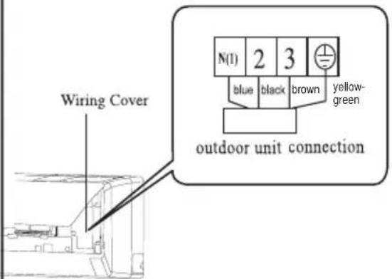
Fig.6
NOTE:
All wires between indoor and outdoor units must be connected by the qualified electric contractor.
● Electric wires must be connected correctly. Improper connection may cause malfunction.
● Tighten the terminal screws securely.
● After tightening the screws, pull the wire slightly to confirm whether it's firm or not.
● Make sure that the electric connections are earthed properly to prevent electric shock.
● Make sure that all wiring connections are secure and the cover plates are reinstalled properly. Poor installation may cause fire or electric shock.

Installation of Indoor Unit
Installation of Indoor Unit
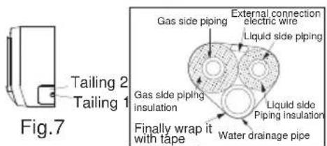
● The piping can be output from right, right rear, left or left rear.
-
When routing the piping and wiring from the left or right side of indoor unit, cut off the tailings from the chassis when necessary(As shown in Fig.7) (1) Cut off tailing 1 when routing the wiring only; (2) Cut off tailing 1 and tailing 2 when routing both the wiring and piping.
-
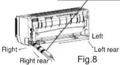
Take out the piping from body case; wrap the piping, power cords, drain hose with the tape and then make them pass through the piping hole. (As shown in Fig.8)
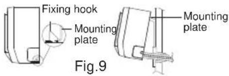
-
Hang the mounting slots of the indoor unit on the upper hooks of the mounting plate and check if it is firm enough. (As shown in Fig.9)
-
The installation site should be 250cm or more above the floor.
Installation of Connection Pipe
- Align the center of the pipe flare with the related valve.
- Screw in the flare nut by hand and then tighten the nut with spanner and torque wrench by referring to the following:
| Hex nut diameter | Tightening torque(N·m) |
| Φ6 | 15~20 |
| Φ9.52 | 30 ~4 0 |
| Φ12 | 4 5~55 |
| Φ16 | 60~65 |
| Φ19 | 70~75 |
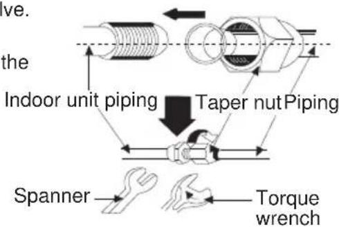
NOTE: Connect the connection pipe to indoor unit at first and then to outdoor unit. Handle piping bending with care. Do not damage the connection pipe. Ensure that the joint nut is tightened firmly, otherwise, it may cause leakage.

Installation of Outdoor Unit
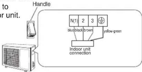
Electric Wiring
- Remove the handle on the right side plate of outdoor unit.
- Take off wire cord anchorage. Connect and fix power cord and signal control wire (only for heat pump unit) to the terminal board. Wiring should fit that of indoor unit.
- Fix the power cord and signal control wire (only for heat pump unit) with wire clamps and then connect the corresponding connector.
- Confirm if the wire has been fixed properly.
- Reinstall the handle.
NOTE:
- Incorrect wiring may cause malfunction of spare part.
- After the wire has been fixed, ensure there is free space between the connection and fixing places on the lead wire.
Schematic diagram being reference only, please refer to real product for authentic information.
Air Purging and Leakage Test
- Connect charging hose of manifold valve to charge end of low pressure valve (both high/low pressure valves must be tightly shut).
- Connect joint of charging hose to vacuum pump.
- Fully open the handle of Lo manifold valve.
- Open the vacuum pump for vacuumization. At the beginning, a loosen joint nut of low pressure valve to check if there is air coming inside (If noise of vacuum pump has been changed, the reading of multimeter is 0). Then tighten the nut.
- Keep vacuuming for more than 15mins and make sure the reading of multi-meter is -1.0 × 10 ^5 pa (-76cmHg)..
- Fully open high/low pressure valves.
- Remove charging hose from charging end of low pressure valve.
- Tighten lid of low pressure valve. (As shown in Fig.10)
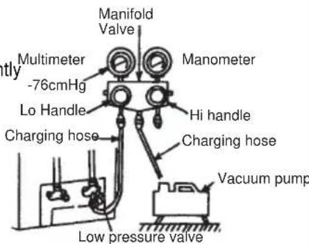
Fig.10
Outdoor Condensate Drainage (only for Heat pump unit)
During heating operation, the condensate and defrosting water should be drained out reliably through the drain hose.
Install the outdoor drain connector in a∅25 hole on the base plate and attach the drain hose to the connector so that the waste water formed in the outdoor unit can be drained out. The hole diameter 25 must be plugged.
Whether to plug other holes will be determined by the dealers according to actual conditions.
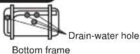

Drain plug
Drain connector Hose (available commercially, inner dia. 16mm)

Check after Installation
| Items to be checked Possible malfunction | |
| Has the unit been fixed firmly? | The unit may drop, shake or emit noise. |
| Have you done the refrigerant leakage test? | It may cause insufficient cooling(heating) |
| Is thermal insulation sufficient? | It may cause condensation. |
| Is water drainage satisfactory? | It may cause water leakage. |
| Is the voltage in accordance with the rated voltage marked on the nameplate? | It may cause electric malfunction or damage the unit. |
| Is the electric wiring or piping connection installed correctly and securely? | It may cause electric malfunction or damage the parts. |
| Has the unit been securely earthed? | It may cause electrical leakage. |
| Is the power cord specified? | It may cause electric malfunction or damage the parts. |
| Is the inlet or outlet blocked? It may cause insufficient cooling(heating) | |
| Is the length of connection pipes and refrigerant capacity recorded? | The refrigerant capacity is not accurate. |
Operation Test
- Before Operation Test
(1) Do not switch on power before installation is finished completely.
(2) Electric wiring must be connected correctly and securely.
(3) Cut-off valves of the connection pipes should be opened.
(4) All the impurities such as scraps and thrums must be cleared from the unit.
- Operation Test Method
(1) Switch on power and press "ON/OFF" button on the remote controller to start operation.
(2) Press MODE button to select the COOL, HEAT (Not available for cooling only unit), FAN to check whether the operation is normal or not.
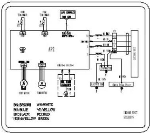
Indoor Unit
For 115V、230V models:
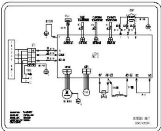
Outdoor Unit
For 230V heat pump type:
flowchart
graph TD
    A["ACF"] --> B["fuses"]
    B --> C["RELays"]
    C --> D[" meters"]
    D --> E["AP1"]
    E --> F[" meters"]
    F --> G[" relays"]
    G --> H[" meters"]
    H --> I[" meters"]
    I --> J[" meters"]
    J --> K[" meters"]
    K --> L[" meters"]
    L --> M[" meters"]
    M --> N[" meters"]
    N --> O[" meters"]
    O --> P[" meters"]
    P --> Q[" meters"]
    Q --> R[" meters"]
    R --> S[" meters"]
    S --> T[" meters"]
    T --> U[" meters"]
    U --> V[" meters"]
    V --> W[" meters"]
    W --> X[" meters"]
    X --> Y[" meters"]
    Y --> Z[" meters"]