EA 1500 FLX - Car stereo Emphaser - Free user manual and instructions
Find the device manual for free EA 1500 FLX Emphaser in PDF.


User questions about EA 1500 FLX Emphaser
0 question about this device. Answer the ones you know or ask your own.
Ask a new question about this device
Download the instructions for your Car stereo in PDF format for free! Find your manual EA 1500 FLX - Emphaser and take your electronic device back in hand. On this page are published all the documents necessary for the use of your device. EA 1500 FLX by Emphaser.
USER MANUAL EA 1500 FLX Emphaser
natural_image
Exterior view of a black EMPHaser industrial sensor module with attached terminal blocks (no visible text or symbols on main body)CUSTOM INSTALL POWER AMPLIFIER
Installation & operating Manual eInbau- & bedlenungsanleitung
Page
1. design Features 5
2. ConneCtions & Controls 6-7
2.1 FRONT PANEL CONNECTIONS 6-7
2.2 REAR PANEL CONNECTIONS 6-7
2.3 REMOTE CONTROL PANEL 6-7
2.4 SPEAKER IMPEDANCES & WIRE INFO 8
3. aMplIFler Mounting 8
4. Wire routing 9
4.1 MAIN POWER WIRES 9
4.2 RCA & REMOTE WIRES 9
4.3 LOUDSPEAKER WIRES 9
4.4 CONNECTION SCHEMATIC 10
4.5 MASTER/SLAVE CONNECTION SCHEMATIC 11
5. CrossoVer adJustMents 12
5.1 LOWPASS CROSSOVER FREQUENCY ADJUSTMENT 12
5.2 SUBSONIC HIGHPASS CROSSOVER ADJUSTMENT 12
5.3 INPUT LEVEL ADJUSTMENT 12
6. teCHnICal speCIFICATIONS 13
7. eMpHaser LIMITED Warranty 26
7.1 WARRANTY LIMITATIONS 26
8. Warranty Card 27
Seite
1. teCHnIsCHer auFbau/MerKMale 15
2. ansCHIÜsse & bedlenungseleMente 16-17
2.1. EINGÄNGE AM FRONT PANEL 16-17
2.2 EINGÄNGE AM REAR PANEL 16-17
2.3 FUNKTIONEN AM REMOTE CONTROL PANEL 16-17
2.4 LAUTSPRECHER-IMPEDANZ & KABELINFO 18
3. Montage des VerstÄrKers 19
And thank you for choosing this EMPHASER EA1500FLX class-D mono amplifier!
To maximize the performance of this amplifier and your car audio system install, we recommend that you acquaint yourself thoroughly with all capabilities and features of the EMPHASER amplifier.
Please read this manual carefully, before attempting the installation and retain this manual and your purchasing / installation receipts for future reference.
IMPORTANT NOTICE:
In case you are installing your EMPHASER amplifier yourself, you should have your installation checked and approved by an authorized professional EMPHASER dealer/installer, in order to qualify for full warranty protection and also, to reach maximum power- and audio performance possible with your individual car audio system.
1. design Features
■ Car audio aMplIFler: This EMPHASER digital mono amplifier allows the cross-over controlled amplification of subwoofer systems
■ reMote Control unit: A compact remote control unit that can be mounted in the trunk compartment of the car. This control device allows adjusting the gain, lowpass- and subsonic-filter in a convenient way.
■ digital aMplification: This EMPHASER amplifier features an extremely efficient class-D circuitry, to guarantee excellent sonic performance and very high power output.
■ 4/2 oHM load stability: This EMPHASER amplifier works totally stable into loads down to 2 ohms. The high damping factor guarantees full control over the connected subwoofer system.
■ Integrated eleCtronIC CrossoVer: The internal crossover section features fully variable subsonic and lowpass filters with crossover slope rates of 24 dB/octave.
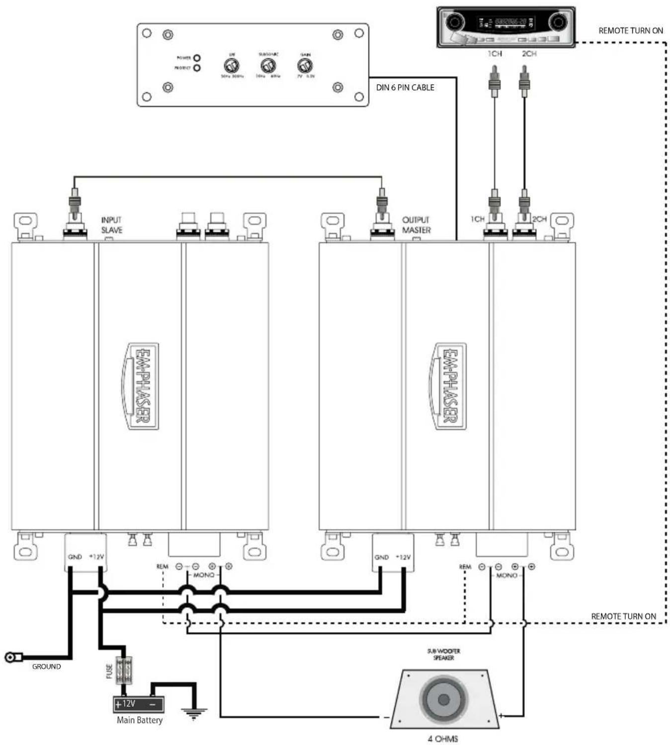
■ Master - slaVe ConFiguration: Two EA1500FLX can be connected together, to obtain a high output power twin-amp configuration, actually doubling the output of one EA1500FLX.
■ unCoMproMIsIng design and ConstruCtion: Only best electrical and electronic components have been used for the assembly of this amplifier. Such as double-sided glass-fiber epoxy circuit boards equipped with high current MOS-FET output devices. The power input side features molded direct power input terminals that accept 25 mm² power wires, for full unrestricted current flow
■ adVanCed proteCtion ClrCultrY: The protection circuitry safe-guards the amplifier from short-circuits at the speaker outputs, DC offset voltage at the outputs and overheating of power electronics.
■ status and proteCtion led's: A blue and a red LED located at the remote control panel enable you to monitor the operating status of your EMPHASER amp.
■ adJustable Input sensItIVItY: The RCA line-input accepts input voltages from 300mV to 7V, providing a good match to the line-output levels of almost any head-unit on the market.
2. CONNECTIONS & CONTROLS
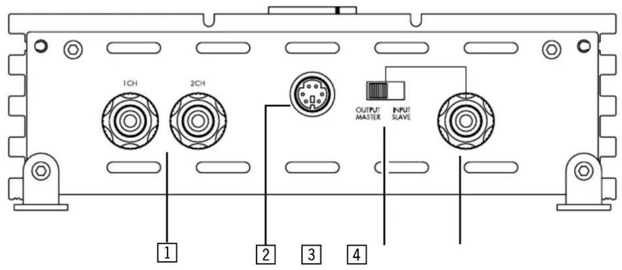
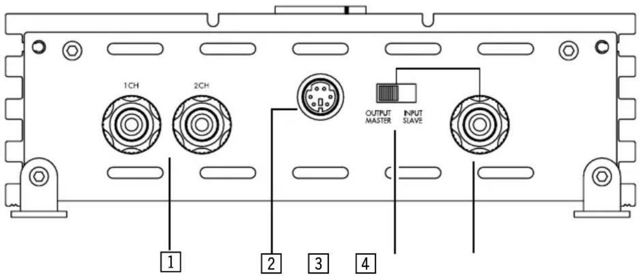
2.1 FRONT PANEL CONNECTIONS
1 RCA INPUTS 1/2-CH
Low-level stereo RCA signal input for connection with line-out of the head-unit (sub-out)
2 REMOTE CONTROL INPUT PORT
DIN socket for connection with the separate remote control unit
Switch to select the operation mode of amplifier. The default setting is MASTER
RCA input/output to branch two EA1500FLX amplifiers in master/slave operation mode
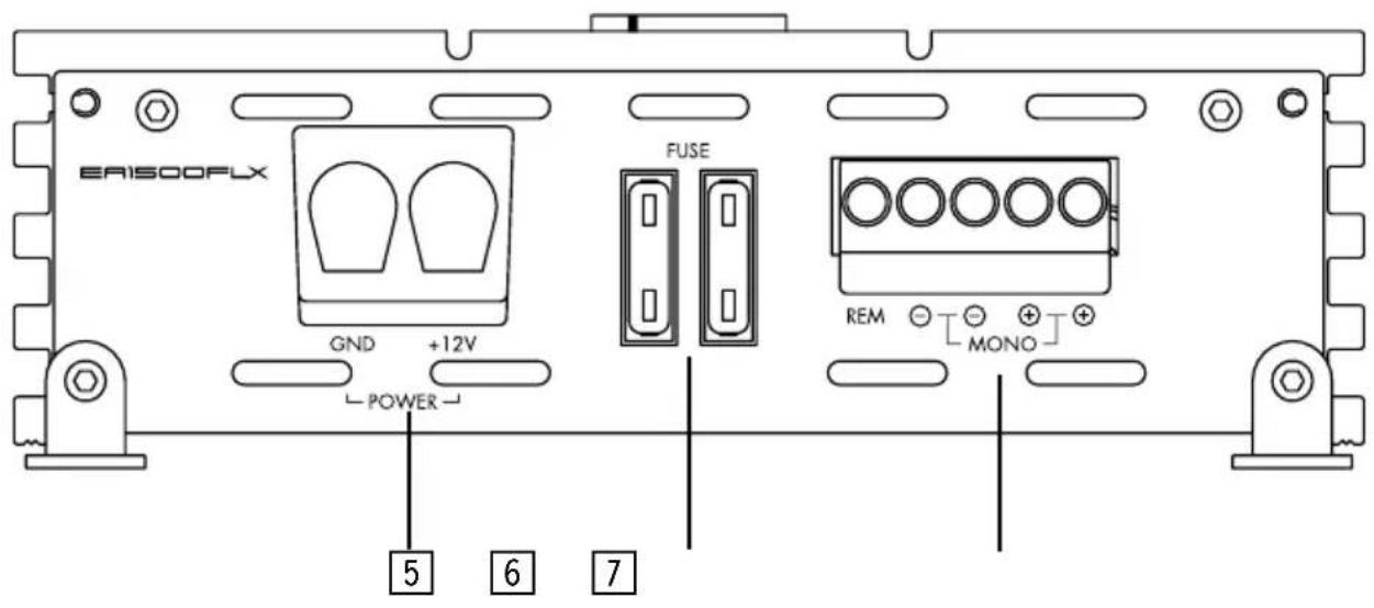
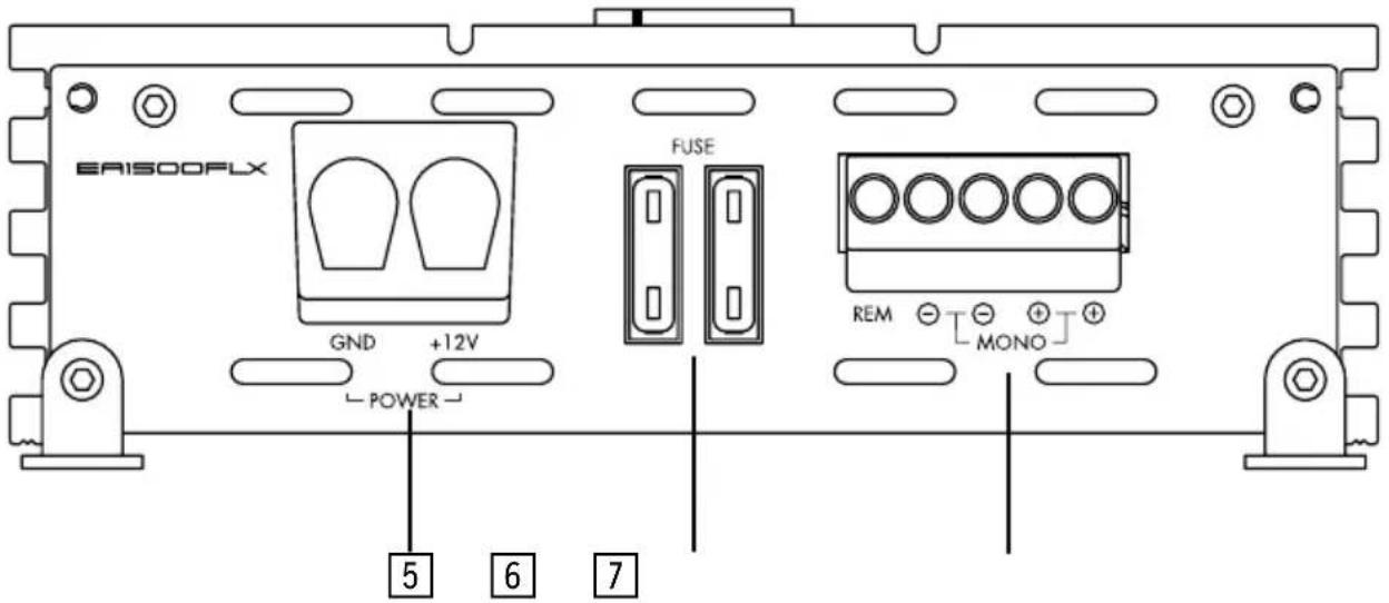
2.2 REAR PANEL CONNECTIONS
5 DETACHABLE POWER INPUT TERMINAL
25 mm ^2 direct power input terminal to connect the amplifier to the positive +12V power wire connected to the car battery and the ground wire connected to the negative or ground wire of the vehicle
6 FUSE TERMINAL
Replace defective fuses only with high quality 30 A fuses
7 DETACHABLE SPEAKER/REMOTE OUTPUT TERMINAL
Terminal to connect the amplifier to the Automatic (remote) turn-on/turn-off lead of the head unit and to connect the loudspeaker output terminal to the subwoofer(s)
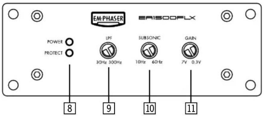
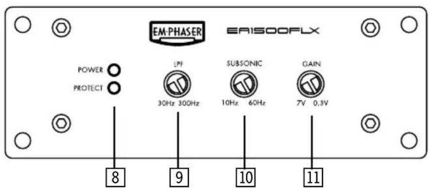
2.3 REMOTE CONTROL PANEL
8 STATUS LEDs
Blue "operation" LED signaling correct operation of the amplifier Red "protection" LED signaling faulty speaker connections or general malfunction of the amplifier
Crossover control potentiometer for the frequency adjustment of the 24dB/oct. low-pass filter
Crossover control potentiometer for the frequency adjustment of the 24dB/oct. subsonic high-pass filter
11 INPUT GAIN CONTROL
Input level gain control potentiometer, allows matching the output voltage of the head-unit's RCA line-outs to the amplifier input
Front panel ea1500FIX
text_image
1CH 2CH OUTPUT MASTER INPUT SLAVE 1 2 3 4rear panel ea1500FIX
text_image
ERISO0FLX GND +12V POWER FUSE REM MONO 5 6 7reMote Control panel ea1500FIX
text_image
EM-PHASER ERISOOFLX POWER PROTECT UPF 30Hz 300Hz SUBSONIC 10Hz 60Hz GAIN 7V 0.3V 8 9 10 112.4 SPEAKER IMPEDANCES & WIRE INFO
The heat dissipation capacity of this amplifier has been designed to cope with low impedance loads. However, EMPHASER laboratories recommend staying at or above the suggested impedance ratings listed below:
EA1500FLX → 2 ohms mono
2 x EA1500FLX in Master/Slave configuration: 4 ohms mono
Note: EMPHASER laboratory recommends a minimum main power cable cross-section (5m total length) of minimum 25mm^2 and 35 mm^2 , when the amp is intended to be operated at full output power for prolonged periods of time. To reduce the diameter down to 25 mm^2 , please use an according power distribution block.
These recommendations guarantee trouble-free operation of your amplifier, giving you full power output.
3. AMPLIFIER MOUNTING
Attention! For your own safety, disconnect the positive battery terminal (+12V) or remove the main fuse in the positive power cable near the car battery, before you start any wiring work!
Before you proceed to install this EMPHASER amplifier, it is recommended to map out the complete audio system and the respective wiring required. Consider all additional electrical requirements and accessories, such as power cables, interconnect cables etc., to complete this install. Please note that - because of possible interference problems with the existing car electrics and electronics - especially the routing of the signal cables and the chassis ground connection will have a profound impact on a trouble-free (noise free!) operation of the amplifier.
The mounting location should be carefully selected and in the interest of passive driver and passenger safety, the amplifier must be securely mounted. Make sure that there is no wiring harness, fuel tank etc. behind or below the mounting surface that may be damaged by the drilling of the holes for the amplifier mounting screws. After installation, there should be a clearance of at least 5cm on all sides including the top of the amplifier heatsink. Make sure the unit is not exposed to direct sunlight, humidity, water, oil or spill of other fluids that may enter the amplifier.
Once the location where the amplifier will be mounted is defined, use the unit as a template for the marking of the mounting holes with pencil or felt-tip marker. The mounting holes should be pilot-drilled, using a 2,5 mm or 3 mm drill bit. Make sure that the housing of the amp does not come into electrical contact with the vehicle.
Important! There must not be a direct contact of the amplifier heatsink, bottom panel or other metal parts to the vehicle chassis ground! Electrical ground-loops can result in audible hum!
4. WIRE ROUTING
4.1 MAIN POWER WIRES
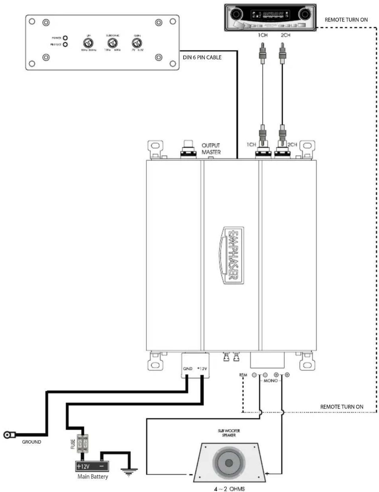
Run the positive main power cable („+12 V“) directly from the positive terminal of the car battery to the amplifier's detachable power terminal. For protection of your car audio system against electrical fire hazards, resulting from a short-circuit of the main power cable to chassis ground a main fuse holder must be inserted within the first 30 cm of the positive main power cable. The applicable fuse value must be matched to the limitations of your main power cable AND the current draw of the amplifier – therefore choose an appropriate fuse value.
Attach the ground cable to the amplifier's detachable power terminal. In most cases it will be best to keep the ground cable („-12V“) as short as possible, i.e. to find a chassis contact very close to the amplifier. The ground power wire must have the same cross-section as the positive power cable. The contact point where the ground wire is attached to, must be solid and clean, i.e. free from rust or paint!
Before connecting the detachable plug to the amplifier, tighten both power input terminals of the plug, and double check for perfect fit of both main cable leads!
4.2 RCA & REMOTE WIRES
Carefully run the audio signal interconnects, the amp remote wire and – if applicable - the cable of the low pass level remote control from the head-unit or dashboard to the amplifier. As mentioned before, the audio signal cables should always be routed completely separate from the power cables. Connect the remote (turn on/turn off) lead to the respective input terminal of the amplifier and to the remote output of your head-unit. Now you can connect the RCA interconnects to the respective outputs of your head-unit and to the inputs of the amplifier. The remote low pass level remote control unit can be mounted in any convenient position where it can be reached while you drive in your car.
4.3 REMOTE & LOUDSPEAKER WIRES
Once the remote and speaker cables have been routed, turn loose the screws of the detachable speaker terminal and – after inserting the stripped remote and speaker cables – re-tighten the screws. When baring wires for connection, remove approximately 6-8mm of the insulation and after axially twisting the wires, insert the bare ends into the corresponding speaker terminal output on the detachable plug. At least connect the detachable terminal to the amplifier.
Close the electrical circuit by inserting the main fuse. Now switch on your head unit. The blue OPERATING LED of the remote control panel should light-up. If the LED lights up red, your installation is wrong! Immediately turn off your head-unit and carefully re-check all installation steps!
4.4 CONNECTION SCHEMATIC
text_image
PONTE PROTECT IP 30Hz 30Hz SUBSTONE 1MHz 6MHz GAIN 7V 6.4V DIN 6 PIN CABLE OUTPUT MASTER 1CH 2CH REMOTE TURN ON GND +12V EMPHASER REM MONO GROUND FUSE +12V - Main Battery REMOTE TURN ON SUB WOOFER STEAKER 4~2 OHMS4.5 MASTER/SLAVE CONNECTION SCHEMATIC
Connect the master/slave ports of both amps with on RCA cable. Select one amp as master and switch the second amp to slave.
text_image
MAIN BATTERY GROUND FUSE +12V - MAIN BATTERY GND +12V GND +12V OUTPUT MASTER EM-PHASER IN 30Hz 300Hz SUBSOURCE 10Hz 4MHz 5MHz 7V 3.5V DIN 6 PIN CABLE 1CH 2CH REMOTE TURN ON GND -12V REM - MONO 5.8 WOOFER SPEAKER 4 OHMS5. CrossoVer adJustMents
5.1 LOWPASS CROSSOVER FREQUENCY ADJUSTMENT
Note: Before you attempt to adjust the lowpass crossover frequency, you must set the subsonic highpass filter to its lowest position (10 Hz).
The LOWPASS cut-off frequency setting depends on some variables. As a rule of thumb, settings in a range between 60 to 90 Hz will render best sonic results. If you use this amp for SPL scores, it is advisable to set the lowpass crossover frequency above 80Hz.
Note: In general, setting the lowpass crossover frequency too low, will result in a weak and muddy sounding bass, while setting this crossover frequency too high will result in a 'booming' bass sound and reduced low end extension.
5.2 SUBSONIC HIGHPASS CROSSOVER FREQUENCY ADJUSTMENT
Adjust the SUBSONIC potentiometer according to your needs. This setting depends on the dimension and the power handling of the installed subwoofer system. The higher the subsonic crossover frequency is set, the higher the mechanical power handling of the connected subwoofer system will be. The trade-off is reduced low end extension! The subsonic highpass can not be bypassed! But you can set the SUBSONIC control to its lowest position at 10 Hz, which will not longer impose an audible effect to the music played.
5.3 INPUT LEVEL ADJUSTMENT
To reach a maximum in dynamic response from each individual head-unit/amplifier/speaker combination, it is important to set the respective input level controls („GAIN“) of this amplifier correctly.
Before you start, you MUST set all tone controls (Bass, Mid, Treble, Loudness etc.) and the fader on the head unit to their neutral or center positions.
Now turn the input gain controls of the installed amplifier anti-clockwise to its minimum position. Set the volume control of your head-unit to approximately 34 of full volume, while playing a dynamic piece of music. Slowly increase the input gain control by turning the GAIN control clockwise until you can just about hear distorted sounds coming out of your subwoofer system. Reduce the main volume level on your head-unit to a medium listening level.
6. teCHnICal speCIFICATIONS
ea1500FIX
CustoM Install Mono aMplIFler
| 300W x 1 @ 4 ohms (< 1.0% THD / 14.4V) |
| 500W x 1 @ 2 ohms (< 1.0% THD / 14.4V) |
| 1000W x 1 @ 4 ohms in master/slave mode (< 1.0% THD / 14.4V) |
| Full MOS-FET class-D amplification circuitry |
| Variable subsonic highpass filter: 10 – 60 Hz with 24 dB/oct. |
| Variable lowpass filter: 30 – 300 Hz with 24 dB/oct. |
| Variable input sensitivity: 0.3 – 7 V |
| Damping factor @ 4 ohms: > 100 |
| Signal to noise ratio: > 80 dB |
| Externally mountable control unit for gain, low-pass filter and subsonic |
| Detachable quick-connect power and speaker terminals |
| Dimensions W x H x D: 190 x 53 x 175 mm |


If at any time in the future you should need to dispose this product please note that waste electrical products should not be disposed of with household waste. Please recycle where facilities exist. Check with your Local Authority or retailer for recycling advice. (Waste Electrical and Electronic Equipment Directive)
1. teCHnIsCHer auFbau/MerKMale
1 CINCH INPUTS 1/2-CH
Front panel ea1500FIX
text_image
1CH 2CH OUTPUT MASTER INPUT SLAVE 1 2 3 4rear panel ea1500FIX
text_image
ERIS00FLX GND +12V POWER FUSE REM MONO 5 6 7reMote Control panel ea1500FIX
text_image
EM-PHASER EAISOOFLX POWER PROTECT LPF 30Hz 300Hz SUBSONIC 10Hz 60Hz GAIN 7V 0.3V 8 9 10 112.4 LAUTSPRECHER IMPEDANZ & KABELINFO
Please read the warranty specifications below carefully.
Should your EMPHASER product require warranty service, please return it to the retailer from whom it was purchased or the distributor in your country. Please do not send any product to EMPHASER Inc. U.S.A. Should you have difficulty in finding an authorized EMPHASER service center, details are available from your local distributor.
This EMPHASER amplifier is fully warranted against defective materials or workmanship for a period of two years from date of purchase at retail. Warranty work will not be carried out unless this warranty certificate is presented fully completed with serial number, purchaser's address, purchasing date and dealer stamp together with the original sales slip and either an authorized dealer's confirmation of installation or authorized dealer's installation approval!
7.1 WARRANTY LIMITATIONS
This warranty does not cover any damage due to:
- Unauthorized or unapproved installation, incorrect audio or mains connection(s).
- Exposure to excessive humidity, fluids, sun rays or excessive dirt or dust.
- Accidents or abuse, unauthorized repair attempts and modifications not explicitly authorized by the manufacturer.
This warranty is limited to the repair or the replacement of the defective product at the manufacturer's option and does not include any other form of damage, whether incidental, consequential or otherwise. The warranty does not cover any transport costs or damages caused by transport or shipment of the product.
7. EMPHASER GARANTIE-BESTIMMUNGEN
Limited Warranty: 24 Months (Valid with authorized Installation Approval only)
Model name:
CUSTOM INSTALL POWER AMPLIFIER EA1500FLX
Date of purchase:
Serial number:
Your name:
Your address:
City:
State: ZIP or Postal Code:
Country:
Your phone number:
Dealer's address & stamp
Installation Approval

Installed by
authorized dealer

Self-installed
by customer
Installation date:
Inspected and
approved by:

text_image
EM·PHASEREMPHASER Inc., Wyoming, Michigan, U.S.A.
Exclusive distributor for Europe & Asia
ACR, Brändli & Vögeli AG, Bohrturmweg 1, CH-5330 Bad Zurzach, Switzerland
Phone: (+41) (0)56 269 64 64, Fax: (+41) (0)56 269 64 65, mail@acr.eu, www.acr.eu
EM·PHASER
WWW.EMPHASER.COM
Emphaser Inc., Wyoming, Michigan, U.S.A.