GP1500.4 - Car stereo Crunch - Free user manual and instructions
Find the device manual for free GP1500.4 Crunch in PDF.


User questions about GP1500.4 Crunch
0 question about this device. Answer the ones you know or ask your own.
Ask a new question about this device
Download the instructions for your Car stereo in PDF format for free! Find your manual GP1500.4 - Crunch and take your electronic device back in hand. On this page are published all the documents necessary for the use of your device. GP1500.4 by Crunch.
USER MANUAL GP1500.4 Crunch
natural_image
Top-down line drawing of a car interior showing front, rear, and side views with no text or symbolsKabelanschlüsse
natural_image
Top-down line drawing of a car interior with a speaker and antenna (no text or symbols)Kabelanschlüsse
natural_image
Simple line drawing of a speaker emitting sound waves (no text or symbols)natural_image
Top-down line drawing of a car front view showing dashboard, front seats, and speaker grille (no text or symbols)Kabelanschlüsse
natural_image
Top-down line drawing of a car interior layout with no text or symbolsKabelanschlüsse
natural_image
Top-down line drawing of a car front view showing speaker and rear-mounted speakers (no text or symbols)Kabelanschlüsse
natural_image
Top-down line drawing of a car interior showing front, rear, and side views (no text or symbols)Kabelanschlüsse
Congratulations on your purchase of a CRUNCH GROUNDPOUNDER Amplifier. These quality audio products are designed and engineered to afford you years of uncompromised musical service. CRUNCH has utilized the latest electronic technologies in order to deliver a superb listening experience.
Contents
Page
General Installation Notes, Installation of the amplifier, Electrical Connection.... 17
2 Channel Amplifier - Features.... 18
4 Channel Amplifier - Features.... 19
2 Channel Amplifier - Applications, One 2 Channel Amplifier in Stereo Mode.... 20
2 Channel Amplifier - Applications, One 2 Channel Amplifier in Mono/Subwoofer Mode.... 21
2 Channel Amplifier - Applications, One 2 Channel Amplifier in Stereo Mode with One 2 Channel Amplifier in Mono/Subwoofer Mode...... 22
4 Channel Amplifier - Applications, One 4 Channel Amplifier with Front-/Rear Speakers...... 24
4 Channel Amplifier - Applications, One 4 Channel Amplifier in Mono/Subwoofer Mode with two Subwoofers.... 25
4 Channel Amplifier - Applications, One 4 Channel Amplifier in 3 Channel Mode with Stereo Front Speakers and Mono Subwoofer.... 26
Specifications.... 27
crunch
USA

text_image
GROUND POUNDERGeneral Installation Notes
The amplifier is generally mounted in the rear trunk area but can be mounted in any convenient area such as beneath a seat. Please be sure to locate this unit where you have reasonable air circulation and protection from moisture. When considering the mounting location you should minimize the length of the power and speaker leads. Minimizing both leads will yield a more reliable installation. It is also important to ensure that the heat sink fins are not against a panel or a surface, preventing air circulation. Do not install the amplifier on a subwoofer box or on vibrating parts of the vehicle, since the vibrations can cause damage to the amplifiers electrical components.
Installation of the amplifier
Mark the location for the mounting screw holes by using the amplifier as a template. Drill holes at the marked locations and firmly fasten the amplifier in place with the mounting screws supplied in the accessory kit.
Before drilling or cutting any holes, investigate the layout of your automobile thoroughly: Take care when working near the gas lines or hydraulic lines and electrical wiring.
Electrical Connection
Ground (GND)
This wire is the electrical ground and must be fastened securely to the vehicle chassis. The best method is to use a threading sheet metal screw since the threads cut into bare metal. Ensure that all paint or other insulation is remove from around the hole area, and using self tapping screw, securely affix the bare wire ends to the vehicle chassis. Use as short a piece of cable as possible - use the same gauge as was used for the +12V cable. Make sure that the connection is safe, a loose connection may result in amplifier noise and fault condition.
Remote (REM)
Many radios or other music sources have an output terminal for connection of the remote turn-on of the power amplifier. If a radio doesn't have a remote turn-on feature, then you can use the antenna relay wire, which activates the antenna motor. Please note, if the power antenna retracts when the radio is operating, then you cannot use the antenna relay wire to operate the remote turn-on.
Batterie Connection (+12V)
This wire is usually connected directly to the positive battery terminal. Ensure that the + power supply wire is fused via an assigned fuse in line with the + power supply wire. Please use a sufficient gauge for the installed amplifiers (min. 10-16 mm ^2 for GP1000.2 and
GP1000.4 or min 16-25 mm² for GP1500.2 and GP1500.4).
This connection must be Completed using spade lug with Insulating sleeve.
Fuses
The integrated amplifier fuses protect the units from short circuit and overload. The fuse rating is for 4 Ohm loads (impedance) of the speakers, for 2 Ohm loads the fuses may have to get increased by up to 50% in case of higher power consumption.
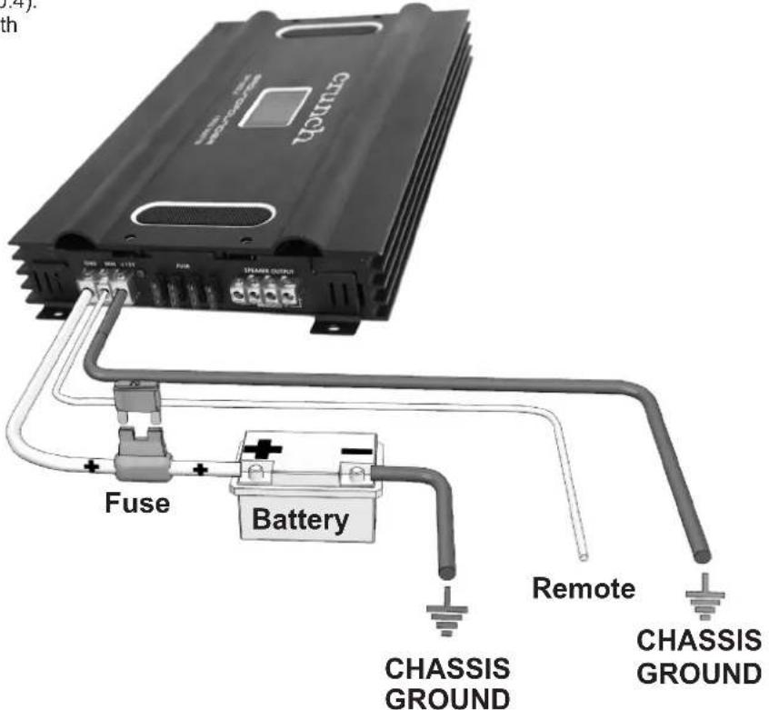
text_image
CRUNCH FUSE Battery Remote CHASSIS GROUND CHASSIS GROUND2 Channel Amplifier - Features
GP1000.2 / GP1500.2
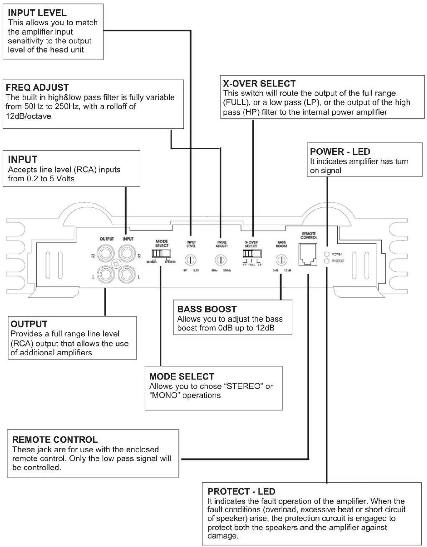
text_image
INPUT LEVEL This allows you to match the amplifier input sensitivity to the output level of the head unit FREQ ADJUST The built in high&low pass filter is fully variable from 50Hz to 250Hz, with a rolloff of 12dB/octave X-OVER SELECT This switch will route the output of the full range (FULL), or a low pass (LP), or the output of the high pass (HP) filter to the internal power amplifier INPUT Accepts line level (RCA) inputs from 0.2 to 5 Volts POWER - LED It indicates amplifier has turn on signal OUTPUT Provides a full range line level (RCA) output that allows the use of additional amplifiers MODE SELECT Allows you to chose "STEREO" or "MONO" operations REMOTE CONTROL These jack are for use with the enclosed remote control. Only the low pass signal will be controlled. BASS BOOST Allows you to adjust the bass boost from 0dB up to 12dB PROTECT - LED It indicates the fault operation of the amplifier. When the fault conditions (overload, excessive heat or short circuit of speaker) arise, the protection circuit is engaged to protect both the speakers and the amplifier against damage.4 Channel Amplifier - Features
GP1000.4 / GP1500.4
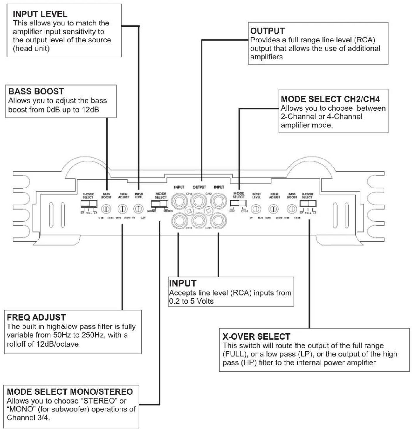
text_image
INPUT LEVEL This allows you to match the amplifier input sensitivity to the output level of the source (head unit) BASS BOOST Allows you to adjust the bass boost from 0dB up to 12dB OUTPUT Provides a full range line level (RCA) output that allows the use of additional amplifiers MODE SELECT CH2/CH4 Allows you to choose between 2-Channel or 4-Channel amplifier mode. FREQ ADJUST The built in high&low pass filter is fully variable from 50Hz to 250Hz, with a rolloff of 12dB/octave MODE SELECT MONO/STEREO Allows you to choose "STEREO" or "MONO" (for subwoofer) operations of Channel 3/4. INPUT Accepts line level (RCA) inputs from 0.2 to 5 Volts X-OVER SELECT This switch will route the output of the full range (FULL), or a low pass (LP), or the output of the high pass (HP) filter to the internal power amplifier2 Channel Amplifier - Applications
GP1000.2 / GP1500.2
One 2 Channel Amplifier in Stereo Mode
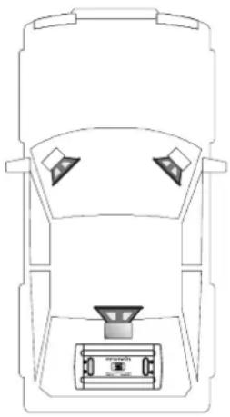
natural_image
Top-down line drawing of a car interior showing front, rear, and side views with no text or symbolsInterconnect cable checklist:
- Connect the INPUT of the amplifier to the head unit line output with good quality RCA to RCA cables.
- Connect the speakers with the terminal block (SPEAKER OUTPUT/ + RIGHT - and + LEFT - and) of the amplifier.
•The minimum final speaker impedance must not be below 2 Ohm per channel. Too low speaker loads result in too high heat dissipation and may cause the amplifier run into protection. - Please observe speaker channel and polarity as printed by the speaker terminal block. Incorrect phasing of the speakers results in total loss of bass response.
Caution
Be careful not to connect speaker (-) to the ground or vehicle chassis.
X-OVER SELECT
- If larger than 20 cm speakers are used, the FULL position is recommended.
- For all smaller speakers ( 8.7cm - 16cm ) the Highpass-Position (HP) is recommended, which eliminates the lowest frequencies and protects the speakers from damage. Set the crossover-frequency between 60Hz - 150Hz , depending of the size of the installed speakers. The Highpass adjustment can be done with the FREQ - ADJUST control.
- Turn the INPUT LEVEL control on the amplifier to 5V position.
- Turn the head unit volume control to about 80 - 90% of its full setting.
- Turn the INPUT LEVEL control clockwise until you hear some distortion.
- Then turn back the INPUT LEVEL control slightly until you can hear clean sound.
INPUT LEVEL
BASS BOOST
- Turn the BASS BOOST control into "0dB" - position.
MODE SELECT
- The MODE SELECT - switch must be in "STEREO" - position.
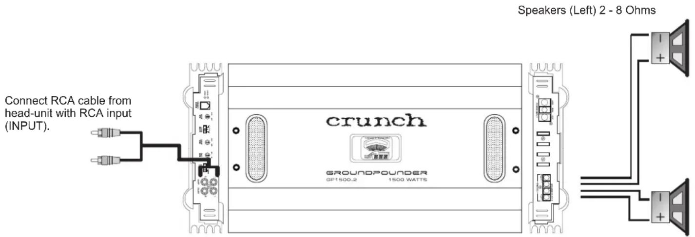
text_image
Connect RCA cable from head-unit with RCA input (INPUT). crunch GROUNDPOUNDER GP1500.2 1500 WATTS Speakers (Left) 2 - 8 OhmsSpeakers (Right) 2 - 8 Ohms
2 Channel Amplifier - Applications
GP1000.2 / GP1500.2
One 2 Channel Amplifier in Mono/Subwoofer Mode
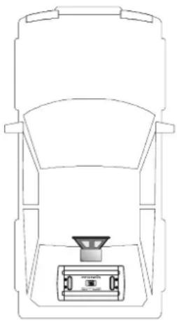
natural_image
Top-down schematic of a vehicle showing front, side, and top views with no text or symbolsInterconnect cable checklist:
- Connect the INPUT of the amplifier to the head unit line output with good quality RCA to RCA cables.
- Connect the speakers with the terminal block (SPEAKER OUTPUT/ + BRIDGED - ) of the amplifier.
•The minimum final speaker impedance must not be below 4 Ohms. Too low speaker loads result in too high heat dissipation and may cause the amplifier run into protection. - If you use more than one speaker (subwoofer), make sure that both are connected in phase. Incorrect polarity of the speakers results in total loss of bass response.
Caution
Be careful not to connect speaker (-) to the ground or vehicle chassis.
X-OVER SELECT
- In 1 Channel/Mono-Mode select the Lowpass-Position (LP), which eliminates the higher frequencies. The recommended crossover frequency ranges between 60 - 100Hz, depending on the size and response of the Subwoofer. The Lowpass adjustment can be done with the FREQ - ADJUST control.
INPUT LEVEL
- Turn the INPUT LEVEL control on the amplifier to 5V position.
- Turn the head unit volume control to about 80 - 90% of its full setting.
- Turn the INPUT LEVEL control clockwise until you hear some distortion.
- Then turn back the INPUT LEVEL control slightly until you can hear clean sound.
BASS BOOST
- The BASS BOOST - Control increases the bass level at 45 Hz max. +12dB. Caution! Please use the Bass-Boost carefully. The additional boost may result in clipping or overload.
MODE SELECT
- The MODE SELECT - switch must be in "MONO" - position.
Connect cable from REMOTE CONTROL with the input jack from the amplifier
Subwoofer 4 - 8 Ohms
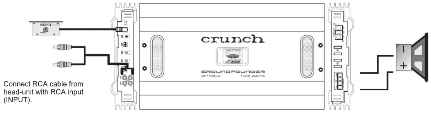
text_image
Connect RCA cable from head-unit with RCA input (INPUT).2 Channel Amplifier - Applications
GP1000.2 / GP1500.2
One 2 Channel Amplifier in Stereo Mode (Front Amplifier) with One 2 Channel Amplifier in Mono/Subwoofer Mode (Rear Amplifier)
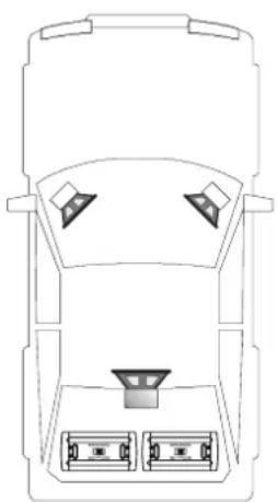
natural_image
Top-down line drawing of a car front view showing dashboard, front seats, and rear seats (no text or symbols)Interconnect cable checklist:
- Connect the INPUT of the Stereo (Front) Amplifier to the head unit line outputs with good quality RCA to RCA cables.
- Connect the OUTPUT of the Stereo (Front) Amplifier with the INPUT of the designated Bass (Rear) Amplifier with a further RCA cable.
- Connect the speakers with the terminal block (SPEAKER OUTPUT/ + RIGHT - and + LEFT -) of the Stereo (Front) Amplifier.
- Connect the Subwoofer with the terminal block (SPEAKER OUTPUT/ + BRIDGED - ) of the designated Bass (Rear) Amplifier.
•The minimum final speaker impedance must not be below 2 Ohms for the Stereo Amplifier, the total impedance of the Subwoofer(s) must not be below 4 Ohms. Too low speaker loads result in too high heat dissipation and may cause the amplifier run into protection. - If you use more than one speaker (Subwoofer), make sure that both are connected in phase. Incorrect polarity of the speakers results in total loss of bass response.
Caution Be careful not to connect speaker (-) to the ground or vehicle chassis.
Control settings of the Stereo (Front) Amplifier:
X-OVER SELECT
- If larger than 20 cm speakers are used, the FULL position is recommended.
- For all smaller speakers ( 8.7cm - 16cm ) the Highpass-Position (HP) is recommended, which eliminates the lowest frequencies and protects the speakers from damage. Set the crossover-frequency between 60Hz - 150Hz , depending of the size of the installed speakers. The Highpass adjustment can be done with the FREQ - ADJUST control.
INPUT LEVEL
- Turn the INPUT LEVEL control on the amplifier to 5V position.
- Turn the head unit volume control to about 80 - 90% of its full setting.
- Turn the INPUT LEVEL control clockwise until you hear some distortion.
- Then turn back the INPUT LEVEL control slightly until you can hear clean sound.
BASS BOOST
- Turn the BASS BOOST control into "0dB" - position.
MODE SELECT
- The MODE SELECT - switch must be in "STEREO" - position.
Control settings of the Bass (Rear) Amplifier:
X-OVER SELECT
- In 1 Channel/Mono-Mode select the Lowpass-Position (LP), which eliminates the higher frequencies. The recommended crossover frequency ranges between 60 - 100Hz, depending on the size and response of the Subwoofer. The Lowpass adjustment can be done with the FREQ - ADJUST control.
INPUT LEVEL
• see descriptions for Stereo Amplifier above
BASS BOOST
- The BASS BOOST - Control increases the bass level at 45 Hz max. +12dB.
Caution! Please use the Bass-Boost carefully. The additional boost may result in clipping or overload.
MODE SELECT
- The MODE SELECT - switch must be in "MONO" - position.
2 Channel Amplifier - Applications
GP1000.2 / GP1500.2
One 2 Channel Amplifier in Stereo Mode (Front Amplifier) with
One 2 Channel Amplifier in Mono/Subwoofer Mode (Rear Amplifier)
Stereo (Front) Amplifier
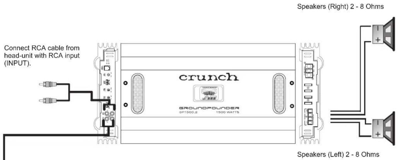
text_image
Connect RCA cable from head-unit with RCA input (INPUT). crunch GROUNDPOUNDER GP1500.2 1500 WATTS Speakers (Right) 2 - 8 Ohms Speakers (Left) 2 - 8 OhmsBass Amplifier
Connect cable from REMOTE CONTROL with the input jack from the amplifier.
Subwoofer 4 - 8 Ohms
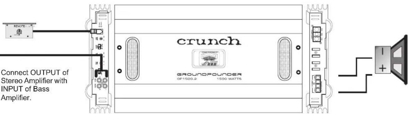
text_image
Remote crunch GROUNDPOUNDER OP1500.2 1500 WATTS Connect OUTPUT of Stereo Amplifier with INPUT of Bass Amplifier.Connect OUTPUT of Stereo Amplifier with INPUT of Bass Amplifier.
4 Channel Amplifier - Applications
GP1000.4 / GP1500.4
One 4 Channel Amplifier with Front-/Rear Speakers
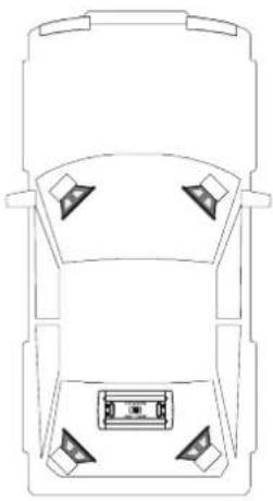
natural_image
Top-down line drawing of a car viewed from the side, showing four corner compartments (no text or symbols)Interconnect cable checklist:
- Connect the head unit line outputs with good quality RCA to RCA cables to the INPUT CH1&2 / CH3&4 of the amplifier.
- Connect the Front-/Rear Speakers with the terminal blocks (SPEAKER OUTPUT / + CH1 - , + CH2 -, + CH3 -, and + CH4 -) of the amplifier.
•The minimum final speaker impedance must not be below 2 Ohm per channel. Too low speaker loads result in too high heat dissipation and may cause the amplifier run into protection. - Please observe speaker channel and polarity as printed by the speaker terminal block. Incorrect phasing of the speakers results in total loss of bass response.
Caution Be careful not to connect speaker (-) to the ground or vehicle chassis.
X-OVER SELECT (CH1/2 & CH3/4)
- If larger than 20 cm speakers are used, the FULL position is recommended.
- For all smaller speakers ( 8.7cm - 16cm ) the Highpass-Position (HP) is recommended, which eliminates the lowest frequencies and protects the speakers from damage. Set the crossover-frequency between 60Hz - 150Hz , depending of the size of the installed speakers. The Highpass adjustment can be done with the FREQ - ADJUST control.
- Turn the INPUT LEVEL controls on the amplifier to 5V position.
- Turn the head unit volume control to about 80-90% of its full setting.
- Turn the INPUT LEVEL controls clockwise until you hear some distortion.
- Then turn back the INPUT LEVEL controls slightly until you can hear clean sound.
INPUT LEVEL (CH1/2 & CH3/4)
BASS BOOST (CH1/2 & CH3/4)
- Turn the BASS BOOST control into "0dB" - position.
MODE SELECT
- The MODE SELECT - switch from CH1/CH2 must be in "4" - position and the MODE SELECT - switch from the CH3/CH4 must be in "STEREO" - position.

text_image
Connect RCA outputs from head-unit with RCA inputs (INPUT CH1/2 and CH3/4). crunch GROUNDPOUNDER DP1500.4 1500 WATTS Rear-Speakers 2 - 8 Ohms Front-Speakers 2 - 8 Ohms4 Channel Amplifier - Applications
GP1000.4 / GP1500.4
One 4 Channel Amplifier in Mono/Subwoofer Mode with two Subwoofers
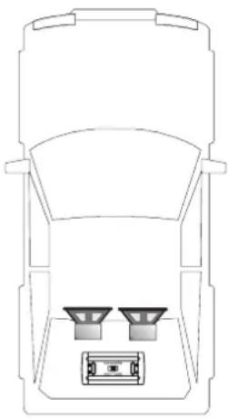
natural_image
Top-down line drawing of a car interior with two speakers and a box (no text or symbols)Interconnect cable checklist:
- Connect the head unit line outputs with good quality RCA to RCA cables to the INPUT CH1&2 of the amplifier.
- Connect the Subwoofers with the terminal blocks (SPEAKER OUTPUT / + BRIDGED - from Channel 1&2 and + BRIDGED - from Channel 3&4) of the amplifier.
•The minimum final speaker impedance must not be below 4 Ohm per channel pair. Too low speaker loads result in too high heat dissipation and may cause the amplifier run into protection. - Please observe speaker channel and polarity as printed by the speaker terminal block. Incorrect phasing of the speakers results in total loss of bass response.
Caution
Be careful not to connect speaker (-) to the ground or vehicle chassis.
X-OVER SELECT (CH1/2 & CH3/4)
- In Mono/Subwoofer-Mode select the Lowpass-Position (LP), which eliminates the higher frequencies. The recommended crossover frequency ranges between 60 - 100Hz, depending on the size and response of the Subwoofers. The Lowpass adjustment can be done with the FREQ - ADJUST control.
INPUT LEVEL (CH1/2 & CH3/4)
- Turn the INPUT LEVEL controls on the amplifier to 5V position.
- Turn the head unit volume control to about 80 - 90% of its full setting.
- Turn the INPUT LEVEL controls clockwise until you hear some distortion.
- Then turn back the INPUT LEVEL controls slightly until you can hear clean sound.
BASS BOOST (CH1/2 & CH3/4)
- The BASS BOOST - Control increases the bass level at 45 Hz max. +12dB. Caution! Please use the Bass-Boost carefully. The additional boost may result in clipping or overload.
MODE SELECT
- The MODE SELECT - switch from CH1/CH2 must be in "2" - position and the MODE SELECT - switch from the CH3/CH4 must be in "MONO" - position.
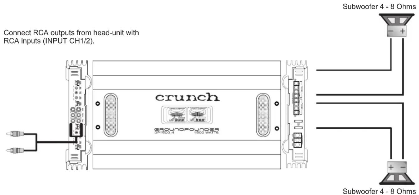
text_image
Connect RCA outputs from head-unit with RCA inputs (INPUT CH1/2). crunch GROUNDPOUNDER SP1500.4 1500 WATT6 Subwoofer 4 - 8 Ohms Subwoofer 4 - 8 Ohms4 Channel Amplifier - Applications
GP1000.4 / GP1500.4
One 4 Channel Amplifier in 3 Channel Mode with
Stereo Front Speakers and Mono/Subwoofer
natural_image
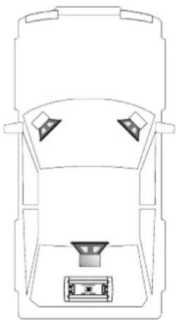
Top-down line drawing of a car interior showing front, rear, and side views (no text or symbols)Interconnect cable checklist:
- Connect the head unit line outputs with good quality RCA to RCA cables to the INPUT CH1&2 / CH3&4 of the amplifier.
- Connect the Front Speakers with the terminal block (SPEAKER OUTPUT / + CH1 - and + CH2 -) of the amplifier.
- Connect the Subwoofer with the terminal block (SPEAKER OUTPUT / + BRIDGED - from Channel 3&4) of the amplifier.
•The minimum final speaker impedance must not be below 2 Ohms Stereo and 4 Ohms Mono. Too low speaker loads result in too high heat dissipation and may cause the amplifier run into protection. - Please observe speaker channel and polarity as printed by the speaker terminal block. Incorrect phasing of the speakers results in total loss of bass response.
Caution Be careful not to connect speaker (-) to the ground or vehicle chassis.
X-OVER SELECT (Front Speakers Channel 1&2)
- If larger than 20 cm speakers are used, the FULL position is recommended.
- For all smaller speakers ( 8.7cm - 16cm ) the Highpass-Position (HP) is recommended, which eliminates the lowest frequencies and protects the speakers from damage. Set the crossover-frequency between 60Hz - 150Hz , depending of the size of the installed speakers. The Highpass adjustment can be done with the FREQ - ADJUST control.
X-OVER SELECT (Subwoofer Channel 3&4)
- In Mono/Subwoofer-Mode select the Lowpass-Position (LP), which eliminates the higher frequencies. The recommended crossover frequency ranges between 60 - 100Hz, depending on the size and response of the Subwoofer. The Lowpass adjustment can be done with the FREQ - ADJUST control.
INPUT LEVEL (CH1/2 & CH3/4)
- Turn the INPUT LEVEL controls on the amplifier to 5V position.
- Turn the head unit volume control to about 80 - 90% of its full setting.
- Turn the INPUT LEVEL controls clockwise until you hear some distortion.
- Then turn back the INPUT LEVEL controls slightly until you can hear clean sound.
BASS BOOST (CH1/2 & CH3/4)
- Turn the BASS BOOST control from the Front Speakers (Channel 1&2) into "0dB" - position.
• The BASS BOOST - Control from the Subwoofer (Channel 3&4) increases the bass level at 45 Hz max. +12dB.
Caution! Please use the Bass-Boost carefully. The additional boost may result in clipping or overload.
MODE SELECT
- The MODE SELECT - switch from CH1/CH2 must be in "4" - position and the MODE SELECT - switch from the CH3/CH4 must be in "MONO" - position.
4 Channel Amplifier - Applications
GP1000.4 / GP1500.4
One 4 Channel Amplifier in 3 Channel Mode with
Stereo Front Speakers and Mono/Subwoofer
Connect RCA outputs from head-unit with RCA inputs
(INPUT CH1/2 and CH3/4).
Subwoofer 4 - 8 Ohms
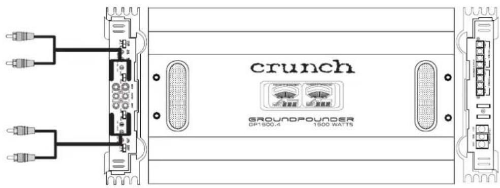
text_image
crunch GROUNDPOUNDER DP1500.4 1500 WATTS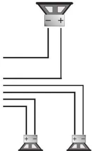
natural_image
Pure electrical circuit lines without any symbolsFront-Speakers 2 - 8 Ohms
Specifications
| GP1000.2 GP1500.2 GP1000.4 | GP1500.4 | |||
| Channels | 2 2 4 | 4 | ||
| Output Power Ratings at 14.4 Volts | ||||
| Watts at 4 Ohms - RMS / MAX. | 2 x 150 / 300 2 x | 225 / 450 4 x 75 / 150 | 4 x 125 / 250 | |
| Watts at 2 Ohms - RMS / MAX. | 2 x 250 / 500 2 x | 375 / 750 4 x 125 / 250 | 4 x 200 / 375 | |
| Output Power Ratings at 14.4 Volts bridged | ||||
| Watts at 4 Ohms - RMS | 1 x 500 1 x 750 | 2 x 250 | 2 x 375 | |
| Watts at 4 Ohms - Max. | 1 x 1000 1 x 1500 | 2 x 500 | 2 x 750 | |
| Frequency response -3dB | 20Hz - 30kHz 20Hz - 30kHz 20Hz - 30kHz | 20Hz - 30kHz | ||
| Damping factor | >200 >200 >200 | >200 | ||
| Signal to noise ratio | >90dB >90dB | >90dB | >90dB | |
| Channel seperation | >74dB >74dB | >74dB | >74dB | |
| THD & N | < 0.5% < 0.5% | < 0.5% | < 0.5% | |
| Input Gain Control | 0.2 - 5 Volt 0.2 - 5 Volt 0.2 - 5 Volt | 0.2 - 5 Volt | ||
| Crossover Channel 1 & 2 | ||||
| Full/Lowpass/Highpass | Full/LP/HP Full/LP/HP Full/LP/HP | Full/LP/HP | ||
| Variable Highpass Crossover 12 dB | 50Hz - 250Hz 50Hz - 250Hz 50Hz - 250Hz | 50Hz - 250Hz | ||
| Variable Lowpass Crossover 12 dB | 50Hz - 250Hz 50Hz - 250Hz 50Hz - 250Hz | 50Hz - 250Hz | ||
| BassBoost Control at 45Hz | 0dB - 12dB | 0dB - 12dB | 0dB - 12dB | 0dB - 12dB |
| Crossover Channel 3 & 4 | ||||
| Full/Lowpass/Highpass | - | - | Full/LP/HP | Full/LP/HP |
| Variable Highpass Crossover 12 dB | - | - | 50Hz - 250Hz | 50Hz - 250Hz |
| Variable Lowpass Crossover 12 dB | - | - | 50Hz - 250Hz | 50Hz - 250Hz |
| BassBoost Control at 45Hz | - | - | 0dB - 12dB | 0dB - 12dB |
| RCA Line Outputs | Fullrange | Fullrange | Fullrange | Fullrange |
| Bass Remote Control | Yes | Yes | - | - |
| Heatsink size in mm | ||||
| Width x Height | 260 x 62 | 260 x 62 | 260 x 62 | 260 x 62 |
| Lenght | 490 | 610 | 490 | 610 |
* All specifications subject to change without notice
crunch
USA
GROUNDO POUNDERS
Distribution:
Audio Design GmbH
Am Breilingsweg 3
76709 Kronau
Tel. 07253/9465-0, Fax 07253/9465-10
www.audiodesign.de