
HCC 360P2 - Uncategorized Dantherm - Free user manual and instructions
Find the device manual for free HCC 360P2 Dantherm in PDF.


| Product Type | Residential Ventilation Unit with Heat Recovery |
| Model | HCC 360P2 (also available as P1 and E1 variants) |
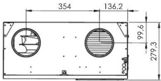
| Dimensions (W x H x D) | 600 x 1122 x 279 mm |
| Weight | 34 kg |
| Power Supply | 230 V AC, 50 Hz |
| Max Power Consumption | 161 W (without preheater), 1061 W (with preheater) |
| Max Nominal Airflow | 220 m³/h |
| Heat Exchanger Type | Counter flow, thermal efficiency up to 94% (DIBt) / 88% (EN 13141-7) |
| Filter Class | ISO Coarse (G4) standard; optional ePM1 (F7) on supply air |
| Duct Connections | 4x Ø125 mm female spigots |
| Mounting | Wall or ceiling (horizontal/vertical), must tilt ≥1° towards drain |
| Operating Ambient Temperature | +12°C to +40°C (installation), outdoor -12°C to +45°C (without preheater) |
| Protection Class | IP20 |
| Cabinet Sound Power Level | 40 dB(A) at reference flow |
| Control Interfaces | Wired remote control (HCP10/11), wireless remote (HRC3), smartphone app, PC Tool (USB) |
| Ventilation Modes | Manual (4 speeds + boost), Week timer (10 preset + 1 custom), Demand (with RH/VOC sensor) |
| Override Functions | Fan boost, summer mode, bypass, fireplace booster, night mode, away mode |
| Special Features | Defrost protection, bypass damper, electric preheater (accessory), humidity sensor (standard), optional VOC sensor |
| Maintenance | Filter check every 6 months, replace annually; clean heat exchanger and fans every 2 years; drain hose annually |
| Accessories | Electric preheater, wired/wireless remote, HAC2 controller, VOC sensor, ePM1 filters |
| Safety & Certifications | CE, Low Voltage Directive, EMC, RoHS; mandatory earthing; fire classification B2 (DIN 4102-1) |
Frequently Asked Questions - HCC 360P2 Dantherm
User questions about HCC 360P2 Dantherm
0 question about this device. Answer the ones you know or ask your own.
Ask a new question about this device
Download the instructions for your Uncategorized in PDF format for free! Find your manual HCC 360P2 - Dantherm and take your electronic device back in hand. On this page are published all the documents necessary for the use of your device. HCC 360P2 by Dantherm.
USER MANUAL HCC 360P2 Dantherm
natural_image
Technical line drawing of a mechanical enclosure or enclosure with labeled parts (FILTER), showing internal structure and mounting holes (no text or symbols beyond labels)Introduction
Table of contents
Table of contents
This service manual covers the following main topics:
Introduction ....3
Table of contents....3
Overview....4
Declaration of conformity 5
Product description 6
Overall description 6
Components description 9
Accessory....10
System operation strategy....11
Installation 12
General location requirements....12
Installation options....14
Mounting....17
Connecting additional equipment 21
Initial calibration 24
Operation (user)....26
Overall ventilation functions 26
User Rights....27
Maintenance and care 28
Preventative maintenance....28
Trouble shooting....31
Appendix 38
Technical data....38
Schematics....40
Week program specification 41
Spare parts....43
Overview
| Manual | This is the service manual for the Dantherm HCC 260/360 residential ventilation unit.Part number of this service manual is 108478 and covers units with serial numbers from:HCC260 P1-A-BP - 2010121652545HCC360 E1-A-BP-RH - 2010131652548HCC360 P2-A-BP-RH - 2010131652549 |
Target group WARNING WARNING | This manual is for both installers and users of the product.Installation and repair of the unit is to be carried out by qualified personnel only. It is theresponsibility of the installer to read and understand this service manual prior to initial startand setup of the HCC 260/360 unit. Warranty is restricted to units, installed by trained person-nel only.This application is not intended for use by persons (including children) with reduced physi-cal, sensory or mental capabilities, unless they have been given supervision or instructionsconcerning the use of the appliance by a person responsible for their safety.Children should be supervised to ensure that they do not play with the appliance.Apart from the replacement of air filters and exterior cleaning of the system, any kind ofmaintenance will require the use of trained personnel. |
 WARNING WARNING | The unit MUST be earthed, through cables WITH earth wire and earthed power supply. |
| Copyright | Copying of this service manual, or part of it, is forbidden without prior written permissionfrom Dantherm |
| Reservations | Dantherm reserves the right to make changes and improvements to the product and theservice manual at any time without prior notice or obligation. |
| Recycling | This units is designed for long term durability. When total lifetime ends, the unit should berecycled according to national rules and with high environmental protection considerations |
 viations in inual viations in inual | This manual uses following abbreviations for ventilation terminologies. |
| Abbr. Description | |
| T1 Outside air coming into the unit | |
| T2 Supply air from the unit to the home | |
| T3 Extract air from the home to the unit | |
| T4 Exhaust air from the unit | |
| S1 Temperature sensor no 1 | |
| S2 Temperature sensor no 2 | |
| S3 Temperature sensor no 3 | |
| S4 Temperature sensor no 4 | |
| Mode A Indicating operation mode A. See more at page 15 | |
| Mode B Indicating operation mode B.(reverse fan) See more at page 15 | |
| G4 Standard air filter class (ISO Coarse) | |
| F7 Filter class (ePM1), better and absorbs finer grains than G4 filter | |
| BP Bypass damper | |
| IP Unique address for the Ethernet port. | |
| DHCP Automatic settings of an Ethernet address provided from an external networkcomponent ( if connecting the unit to Ethernet) | |
| PC Personnel computer running MS Windows | |
| USB Universal serial bus connection- located on almost any computer | |
| LAN Local area network is the internal network with or without wireless access | |
| VOC Volatile organic compounds sensor, controls the ventilation level depending onthe pollution of the air. | |
| PC Tool Windows software application specific for this unit. |
Declaration of conformity
Declaration of Conformity
CE
Dantherm hereby, declare that the unit mentioned below:
No.: 352444 Type: HCC 260/360
- complies with the following directives:
2014/35/EU Low Voltage Directive
2014/30/EU EMC Directive
2014/53/EU RED
2009/125/EC Eco Design Directive (incl. Regulation 2014/1253)
2011/65/EU RoHS Directive
1907/2006/EC REACH Regulation
- and is manufactured in compliance with the following standards:
EN 60335-1:2012 Household and similar electrical appliances - Safety - Part 1
EN 60335-2-40:2003 Household and similar electrical appliances - Safety - Part 2-40
EN 61000-3-2:2014 Electromagnetic compatibility (EMC) - Part 3-2
EN 61000-3-3:2013 Electromagnetic compatibility (EMC) - Part 3-3
EN 61000-6-2:2005 Electromagnetic compatibility (EMC) - Part 6-2
EN 61000-6-3:2007 Electromagnetic compatibility (EMC) - Part 6-3
EN 60730-1:2011 Automatic electrical controls for household and similar use - Part 1
EN 62233:2008 Measurement methods for electromagnetic fields of household appliances
EN 55014-1:2006 Electromagnetic compatibility - Requirements for household appliances - Part 1
EN 55014-2:1997 Electromagnetic compatibility - Requirements for household appliances - Part 2
EN 301 489-1 V1.9.2 ElectroMagnetic Compatibility (EMC) standard for radio equipment and services; Part 1
EN 301489-3 V1.6.1 ElectroMagnetic Compatibility (EMC) standard for radio equipment and services; Part 3
EN 300 220-1 V2.4.1 ElectroMagnetic compatibility & Radio spectrum Matters (ERM); Short Range Devices
EN 300 220-2 V3.1.1 ElectroMagnetic compatibility & Radio spectrum Matters (ERM); Short Range Devices
EN 13141-7:2010 Ventilation for buildings - performance testing of components/products for residential ventilation
Skive, 24.09.2020

Product manager
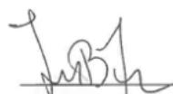
Managing director Jakob Bonde Jessen
Product description
Overall description
Introduction
HCC 260/360 residential ventilation unit is designed to supply fresh air to residential home, by exchanging heat from outgoing air to incoming air, resulting in low heat energy loss.
These units are designed for installation underneath a ceiling, in dry surroundings, with temperatures >12^ C. e.g. utility room or similar heated rooms.
The duct connections can be electronically swapped, providing ability to route the connected ducts, either to the right or to the left, as described on page 15
Product illustration
This illustrates the unit, without the steel drip tray:
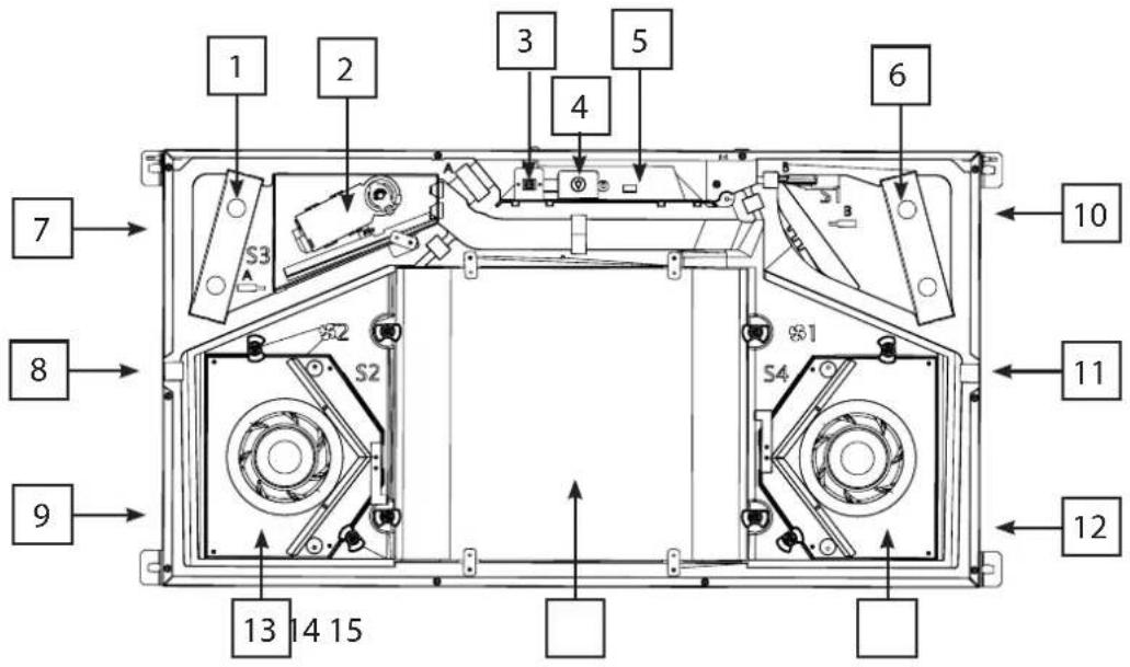
Fig. 1
Part description
This table shows the parts according above illustration:
| Pos Mode A(default) Mode B | ||
| 1 Extract filter ISO Coarse Supply filter ISO Coarse or ePM1 | ||
| 2 Bypass module | ||
| 3 USB connection | ||
| 4 Filter reset button | ||
| 5 Controller PCB (external connections see page 21) | ||
| 6 Supply filter ISO Coarse or ePM1 Extract filter ISO Coarse | ||
| 7 Extract air - T3 Outside air - T1 | ||
| 8 | Blocked | Water drainage spigot |
| 9 Supply air - T2 | Exhaust air-T4 | |
| 10 | Outside air - T1 | Extract air - T3 |
| 11 Water drainage spigot | Blocked | |
| 12 | Exhaust air - T4 | Supply air - T2 |
| 13 | Supply fan | Extract fan |
| 14 | Heat exchanger | |
| 15 | Extract fan | Supply fan |
HCC 260/360
variants
P1, P2, E1
There are three different variants of the HCC 260/360 unit: P1, P2, E1. The function and installation of the unit is exactly the same.
The variants only differ by either heat exchanger or ventilator thus influencing the performance of the unit.
The product label showing the variant is placed on the cover for PCB access beside the filter reset button (see fig. 2).
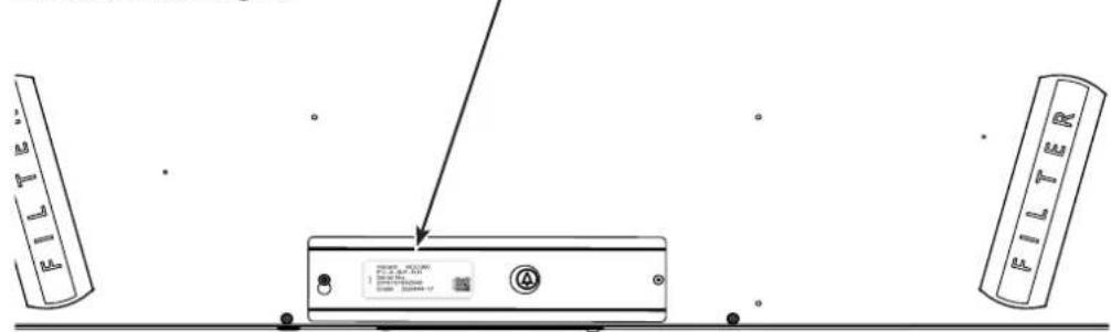
Fig. 2
Airflows
This illustration shows the air flow paths, through the unit. See more about changing operation mode at page 16
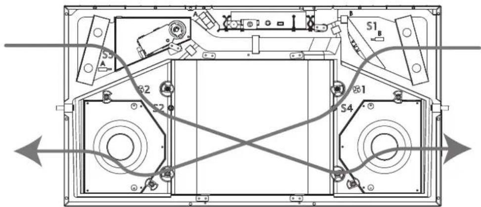
Fig. 3
Sensor placement
This illustration shows correct placement of sensors (if available) are placed inside the unit. See also "Part description" on page 6
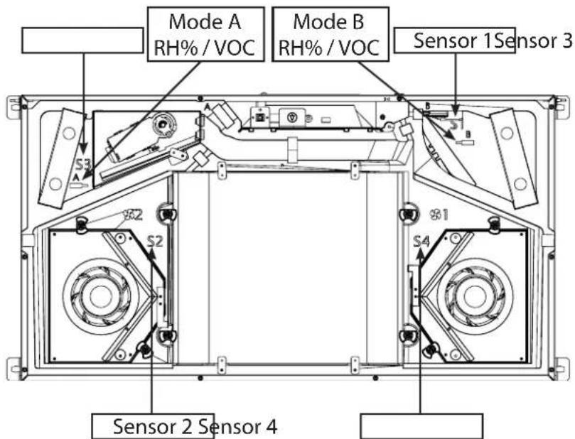
Fig. 4
Sensor function according operation mode:
| Sensor Mode A Mode B | |
| 1 Outside air - T1 Extract air - T3 | |
| 2 Supply air - T2 Exhaust air-T4 | |
| 3 Extract air - T3 Outside air - T1 | |
| 4 Exhaust air - T4 Supply air - T2 | |
Components description
| Introduction | This section describes the individual components which are included in the HCC 260/360 unit. Please use the illustration on page 6 for reference. |
| Cabinet | Cabinet outer parts are made of aluzink sheet metal. The inner part is one moulded polystyrene block. If adding accessory or exchanging parts, access to all parts are available, just by removing the front cover and drip tray.The cabinet is internal sound and heat insulated, with fire retardant polystyrene foam. The unit's cabinet is designed for mounting in 12^ - 40^ C ambient temperature |
| Heat exchanger | The counter flow heat exchanger absorbs the heat energy from extract air and moves this heat energy to the ingoing supply air, resulting in domestic ventilation with low heat loss. |
| Fans | The supply fan supplies fresh outdoor air through the unit's heat exchanger to the ducts, where it's distributed to bedrooms, living rooms and possibly sauna or steam bath.The extract air fan draws used, moistened and polluted air from house, through the unit and heat exchanger, where the heat is transferred to supply air. |
| Bypass damper | The motorized bypass damper overrides the heat exchanger functionality. This is used in warm summer conditions, where colder outside air can be used for reducing inside temperature, when inside temperature exceeds an upper temperature limit. |
| Controller | The unit's main controller is named main PCB. It electrically connects all electrical and electronic parts and various accessory components. |
| Temperature sensor | Units are fitted with 4 temperature sensors that continuously monitor the temperature changes on 4 sides of heat exchanger, i.e. in outdoor air, in supply air, in extract air and in exhaust air. |
| Humidity sensor | The HCC 260 P1 unit, is not default fitted with a RH sensor. RH sensor is available as an accessory.HCC 360 P2 and E1 units are fitted with an RH sensor in the extract duct.The humidity sensor will continuously monitor the quality of the extract air, and adjust the air flow level accordingly. This operation is named demand mode.If an HRC remote control is connected, the level will be shown in the display using 3 level icon.Using demand mode will result in the correct level of ventilation with lowest possible electrical power consumption. |
| Filters | The unit is fitted with two ISO Coarse class cassette filters. These filters protect the heat exchanger and improve the indoor climate by removing dust and particles in both airflows.As alternative/accessory, an ePM1 class filter can be obtained. If ePM1 is used, then it is always placed in the supply air, removing even smaller particles. |
| Water drainage | The unit is fitted with 2 pcs. spigot connections for draining condensed water. It is mandatory to fit the spigot next to the T4 with a hose, discharging the condensed water to a sever.Correct drainage is shown on the connection label placed on the unit. The remaining unused drain is to be blocked with the enclosed cap. |
| Hanging rail | The unit is delivered with hanging rail. |
Accessory
| Introduction | The unit is delivered from factory, without any accessories mounted. These are to be installed prior to initial unit installation or alternative after commissioning, if further functionality is requested. The detailed installation of one or more accessories, is illustrated on the leaflet following each accessory. | |
| Electric preheating | The unit can be fitted with an electrical preheating element that preheats the incoming air. The preheater increases the outside air temperature going into the heat exchanger, and thereby reduces the risk of ice in the heat exchanger in very cold conditions. The preheater is an external enclosure, connected and controlled by the HCC 260/360 controller. | |
| Hand held Remote control | For controlling HCC 260/360 units, Dantherm recommends using remote control, designed for this range of units. | 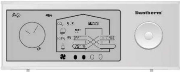 Fig. 5 Fig. 5 |
| Wired Remote Control (HCP 10/11) | A wired remote control (HCP 10/11) without display can be connected to the unit as an alternative to the hand held remote control. | 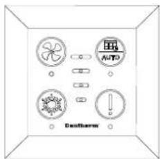 Fig. 6 Fig. 6 |
| Accessory control (HAC 2) | Connect a number of additional accessories to the HCC 260/360 unit via an accessory controller: HAC 2. | 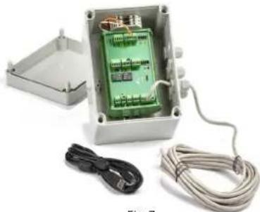 Fig. 7 Fig. 7 |
| VOC and humidity sensors | HCC 260/360 can be fitted with Humidity (RH%) (if not already included as standard) and/or VOC (organic chemicals) sensors. These sensors will continuously monitor the extract air, and adjust the air flow level accordingly. This will result in adequate level of ventilation, with lowest possible electrical power consumption. If a remote control is connected, the sensor level will be shown in the display using 3 level icon. | 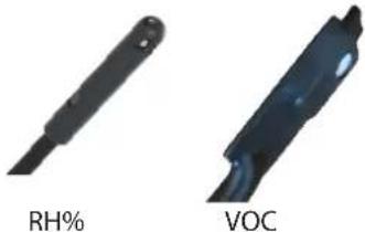 Fig. 8 Fig. 8 |
| Filters | Replacement of filters in sets of 2 ISO Coarse filters or 1 ISO Coarse plus 1 ePM1 (pollen) filter. | |
System operation strategy
| Introduction | This section describes the operation strategy in various conditions. For a user specific running operation see page 26. |
| Defrost | In cold conditions where T1 is below -4°C and exhaust T4 is <+8°C the condensed water could built up as ice in the heat exchanger, blocking the air path and eventually destroying the heat exchanger.In order to prevent this sequence is initiated:The supply fan speed will decrease with 3 rpm/second until minimum RPM is reached.After 10 seconds at this speed the supply fan will stop completely, while the ongoing exhaust fan is supplying warmer air into the heat exchanger component, to remove any potential ice.When T4 yet again is>+8°C the supply fan will start at minimum RPM, and then increase speed with 3 rpm/second until the original required speed is regained.If T4 becomes <+2°C during the speed increase cycle, the supply fan will decrease speed again.If T1<= -13°C for more than 4 minutes and 25 seconds, even with defrost mode active, the unit will stop all operation for 30 minutes, and reattempt previous operation condition. If electrical preheat is present, this total off mode is disabled.The defrost operation will create an under pressure inside the house, so if fireplace mode is enabled, and defrost is necessary; the unit will stop all operation in 4 hours instead. Set-points cannot be changed.When defrost is active any connected remote control will show dEF in the display, and when defrost has shut all off, the display will flash the T1 temperature |
| Preheat (Accessory) | If the preheater is installed, the unit will add electrical heat to the incoming outdoor air, in order to increase the temperature of outdoor air entering the heat exchanger and thereby reduce or eliminate the possibility of going into defrost mode and to ensure balanced operation as long as possible.Preheater can be "master" enabled/disabled on the wireless remote control in installer modePreheat is applied before the T1 sensor.If outside temperature is <+3°C or supply air is <+16,5°C the preheater will switch on with 10% power.The power will increase/decrease 10% for each 60 seconds depending on the T1 or T2 temperature.Temperature set-points are fixed. |
Installation
General location requirements
Introduction
The HCC 260/360 must fulfil all of the previous consideration prior to starting any installation process.
Location and duct connections
The following should be considered selecting an appropriate location for installation:
- The HCC 260/360 units, is designed to be mounted in dry surroundings, with temperatures >12°C like in utility rooms or similar heated rooms.
- The HCC 260/360 can be mounted vertically or horizontally. Please ensure that the ceiling or walls structure is adequate to withstand the additional weight of the unit.
- The air flow direction can be electronically swapped, providing ability to route the connected ducts, either to the right or to the left. See more about swapping at page 16.
- It is mandatory to tilt the HCC 260/360 minimum 1° towards the drain. The enclosed bracket provides this requirement, in case of horizontal ceiling.
Reserve additional space
The HCC 260/360 is designed for hidden installation. It is very important to leave additional space:
- Adequate space for exchanging the unit if needed, including turning the unit into its bracket and up, if mounting underneath the ceiling.
- External preheater (accessory), which is mounted external into the duct system on the T1 incoming outside air, minimum 320 mm from the unit.
- Additional space, in order to inspect and test any drainage hose, also if no preheater is installed..
This applies also for after sales situations, where the unit is to be dismounted completely for service. Any warranty claim will not be acknowledge if these above requirements are not fulfilled.
See min. measurements on page 13.
Service space, ceiling
If installing the unit underneath the ceiling, please reserve space for the tilting up/down, and additional space, if electrical preheater is installed.
Additional space dimensions here shown in operation mode A
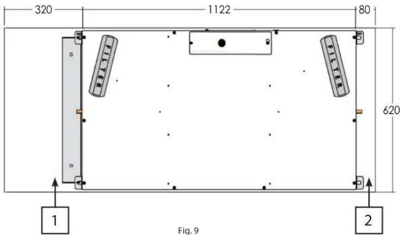
and here shown in operation mode B
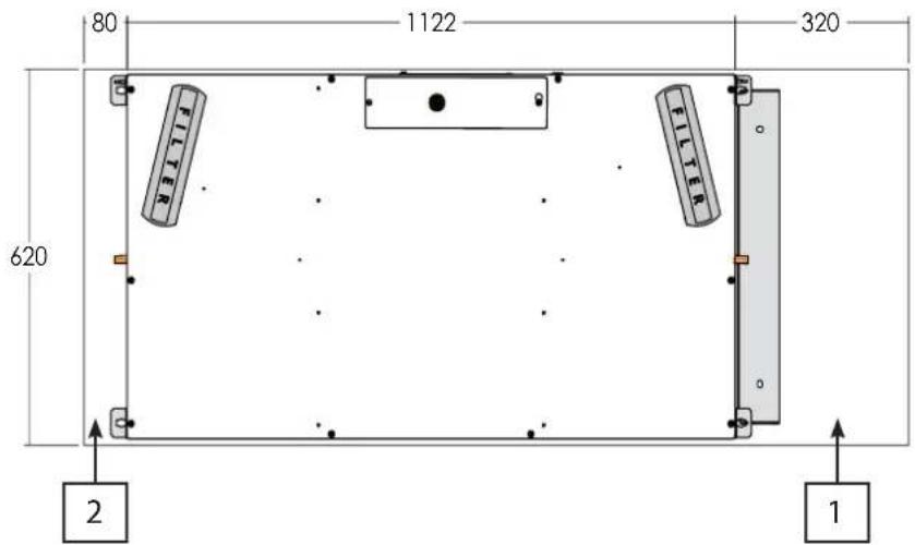
Fig. 10
No Description
1 This space is mandatory in order to lift the unit upwards in its wall bracket. Please ALWAYS mount the bracket and reserve this space, at the unit end, in which the T1 and T4 (cold ducts) are connected. If preheater is installed, this additional space is required to make future service if needed.
2 In order to be able to mount the screws into the ceiling properly, please add minimum this space shown
Service space, wall
If installing the unit onto the wall, always have the T1 and T4 (cold ducts) in the bottom of the unit. If the unit has additional preheater, please allow space for this as well, see illustration.
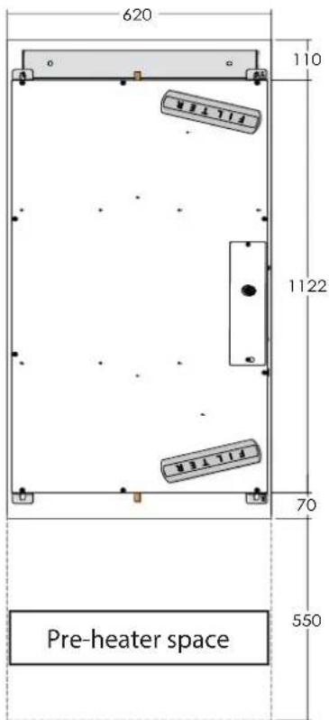
Fig. 11
Installation options
Introduction
HCC 260/360 has a variety of installation options such as vertical or horizontal mounting, flexible cable routing and duct connections making the unit adaptable to different locations. Check the installation options and decide how the installation best fulfils the local demands.
Vertical or horizontal
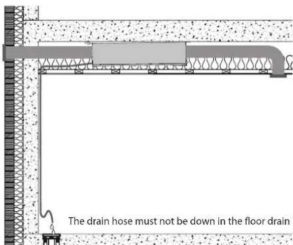
Fig. 12
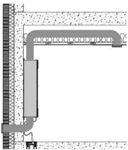
natural_image
Cross-sectional diagram of a structural joint or pipe system with embedded components and reinforcement (no text or labels)Fig. 13

NOTICE
Please ensure that the ceiling or walls structure is adequate to withstand the additional weight of the unit.
Remember to reserve the mandatory service space.
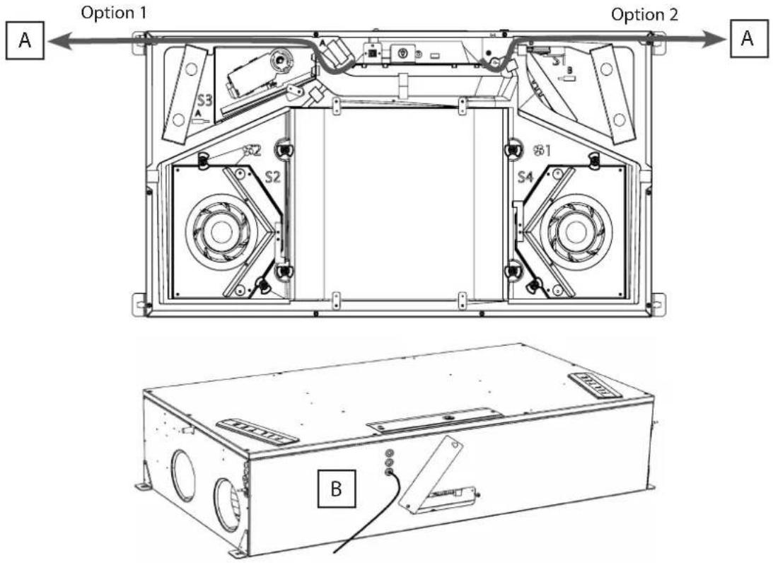
Cable routing
All cable connection can be routed inside the unit, for exit through both end plates (fig. A). Alternatively connect as shown in fig. B. This enables the installer to route and connect cables in best suitable way.
Selecting mode A or B
The air ducts going into the house can either be connected on the right hand side or the left hand side. The default mode is mode A. (Follow procedure on page 16 for swapping to mode B)
Illustration of duct connections in operation mode A:
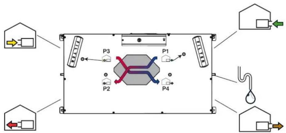
flowchart
graph TD
    A["Home Control"] --> B["Sensor P1"]
    B --> C["Sensor P2"]
    C --> D["Sensor P3"]
    D --> E["Sensor P4"]
    E --> F["Output"]
    style A fill:#f9f,stroke:#333
    style B fill:#ccf,stroke:#333
    style C fill:#cfc,stroke:#333
    style D fill:#fcc,stroke:#333
    style E fill:#cff,stroke:#333
    style F fill:#ffc,stroke:#333
Fig. 14
Illustration of duct connections in operation mode B:
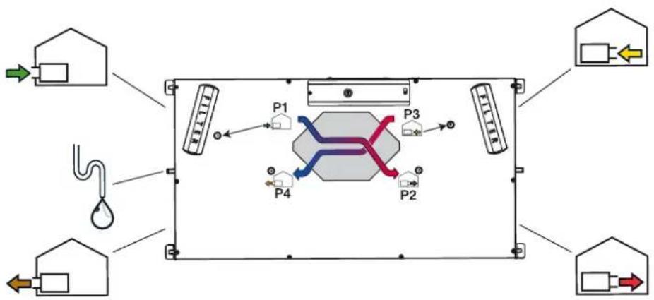
flowchart
graph TD
    A["Household"] --> B["Refrigerator"]
    B --> C["Valve 1"]
    B --> D["Valve 2"]
    B --> E["Valve 3"]
    B --> F["Valve 4"]
    B --> G["Control Unit P1"]
    B --> H["Control Unit P2"]
    B --> I["Control Unit P3"]
    B --> J["Refrigerator"]
    B --> K["Refrigerator"]
Fig. 15

WARNING
Always disconnect the power by removing the 230V plug from the socket, before opening the unit!
Swapping to mode B
If local systems demand mode B, follow the below procedure AND check the label in order to connect the water drainage correctly.
| Step Action Illustration | ||
| 1 | Locate the small lid on the long side of the unit closest to the filter lids. | 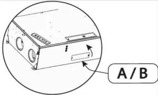 |
| 2 | Locate the switch on the main PCB The default is mode A as shown. To select mode B slide the switch to the right. Close the lid again. | 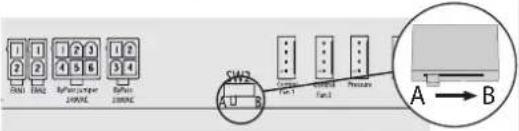 |
| 3 | Swap the drain hose and plug as indicated.For a further description of the drain hose installation, see page 20. | 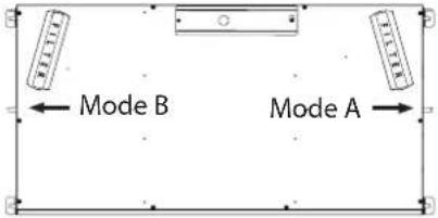 |
| 4 To swap the RH sensors, open sidepanel and look for the marking "A" and "B" | Mode A Mode B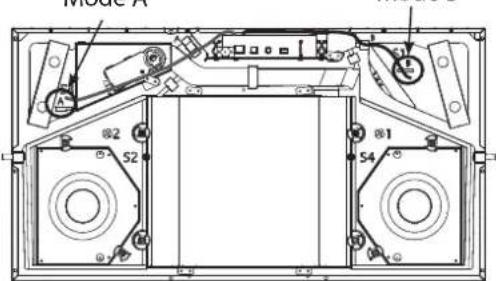 | |
| 5 | Swap the filter (ONLY if the optional pollen filter ePM1 is used for the supply air).Check the table on page 6 in order to determine the right position of the ePM1 filter during mode A/B. | 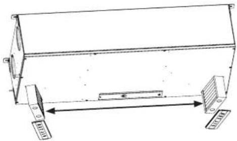 |
| 6 | Place new B sticker and calibration sticker on the unit. | |
| 7 | Connect the duct as specified on the label and described on page 19. | |
| 8 | Calibrate the unit as described on page 24. | |
Mounting
Multi purpose mounting bracket
The enclosed bracket can and should be used, both for wall and for ceiling installation. The bracket will automatically tilt the unit 1° towards the condensate drain, when mounted underneath the ceiling (fig. 16) and when mounted on the wall (fig. 17).
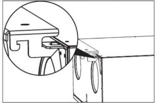
natural_image
Technical line drawing of a mechanical assembly with a magnified inset showing a detail (no text or symbols)Fig. 16 Fig. 17
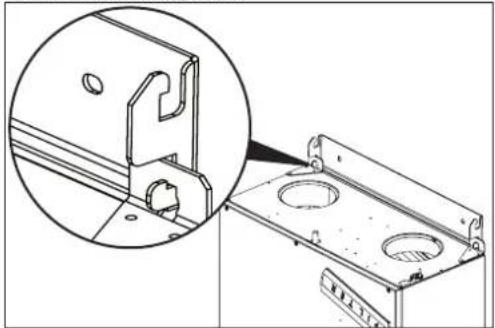
natural_image
Technical line drawing of a mechanical bracket assembly with an inset magnified detail (no text or symbols)Wall mounting
Please follow this procedure to install the HCC 260/360 vertical onto a wall.
Step Action Illustration
| 1 | Drill two holes for the bracket, fulfilling all dimension requirements shown in the section “General location requirements” on page 12. | 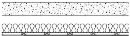 |
| 2 | Mount the bracket with appropriate screws | |
| 3 Lift the unit onto the bracket | ||
| 4 | Drill and mount two appropriate screws in the lower unit bracket | |
| 5 | Connect ducts according illustration at page 15 IMPORTANT: the T1 and T4 outside air ducts, must ALWAYS be routed to the duct connections in the bottom | |
| 6 | Connect ducts and drain hose. | |
Under ceiling installation
Please follow this below procedure for ceiling installation
Step Action Illustration
| 1 The HCC 260/360 should always tilt minimum 1° towards the drain side(T4). This is achieved when using the enclosed bracket, placed at T4 end of unit. Drill two holes and mount the bracket into the ceiling configuration setup (see page 17) Please allow minimum 320 mm to the ceiling edge, in order to have room for turning the unit in step 2. | 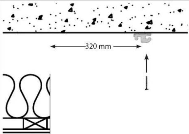 |
| 2 Lift the unit onto the bracket hanging freely as shown | 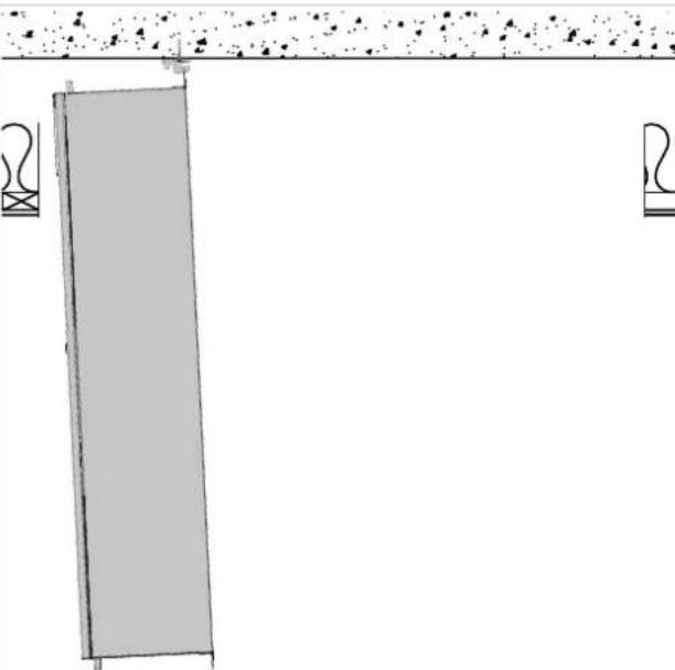 |
| 3 Turn the unit towards the ceiling, and secure it with two screws | 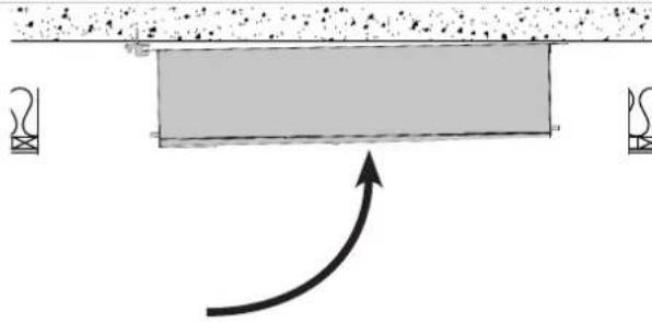 |
| 4 Connect ducts and drain hose. | |
Connect duct system
Connect ducts (specification according local regulations), with spigot connection only.
WARNING: NEVER screw any spigot for ducts, directly onto the sheet metal of the unit.
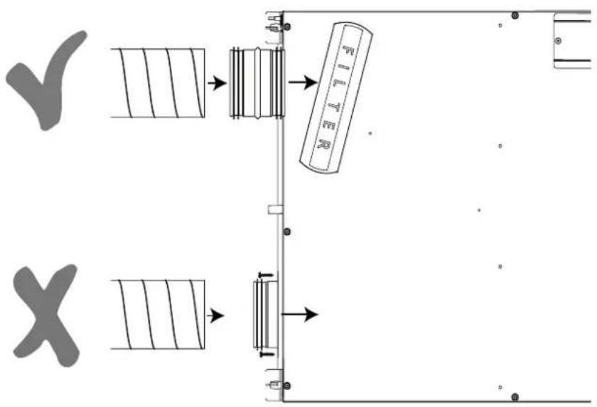
Fig. 18
Insulate the ducts according local requirements, taking the installation surrounding temperature into consideration.
Secure ducts
Make sure that all ducts are well attached and secure, and ALWAYS fixed securely to the ceiling or wall with brackets
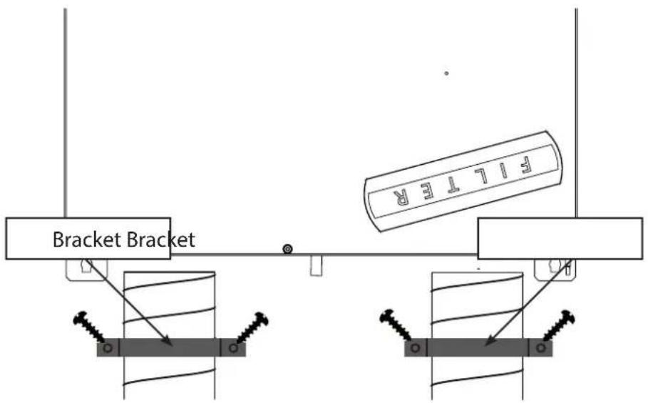
Fig. 19
Drainage consideration
It is mandatory in any HCC 260/360 installation to connect a water drain hose to the unit, because the humidity from the extract air condensates to water drops when cooled in the heat exchanger.
This water is harmful to its surrounding if not managed correctly. The installation thus needs a condensate water drain hose connected with a decline of minimum 10 Promille (1 cm/meter) away from the unit and the hose must NEVER exceed the level of the lower sheet metal plate.
Correct installation

The drain hose has a correct and steady fall towards the sewer.
Faulty installation

The drain hose must never be raised above the bottom plate!
Fig. 20
Condensate drainage
After guiding the hose downwards to a drain, it needs a closing loop. This will block air from escaping through the hose. Please make either a complete closed loop, or a siphon loop on the hose as illustrated, and make sure it has a minimum height of 100 mm. Fill the siphon/loop with min. 0,5 l. water before connecting the hose to the unit.
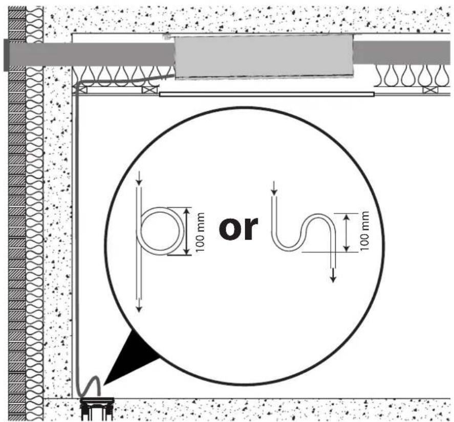
Fig. 21
Connecting additional equipment

WARNING
Connecting additional equipment is to be carried out by qualified personnel only. Always disconnect the power by removing the 230V plug from the socket, before opening the unit!
Access to connections
The integrated controller has various options to connect additional external equipment. To gain access to the controller, please open the print cover (A) of the unit, by turning it all the way around as shown in fig. 22.
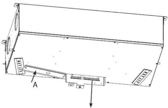
natural_image
Technical line drawing of a mechanical enclosure or enclosure with labeled components (no text or symbols present)Fig. 22
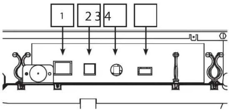
External connections options
This illustration shows the various connections:
flowchart
graph TD
    A["1"] --> B["Box 1"]
    C["2"] --> D["Box 2"]
    E["3"] --> F["Box 3"]
    G["4"] --> H["Box 4"]
    I[" "] --> J["Box 5"]
    K[" "] --> L["Box 6"]
    M[" "] --> N["Box 7"]
    O[" "] --> P["Box 8"]
Fig. 23
| Connection Description | |
| 1: ETHERNET | LAN connection for connecting to wireless router for BMS and smart phone app. functionality. |
| 2: MODBUS Modbus connection for hardware accessory modul (HAC or HCP 10) | |
| 3: ANTENNA Wireless connection point for proprietary remote control. | |
| 4: DIG IN | External digital input, to select specific operations. Parameters can be set in the PC Tool. |
Cable installation
Pull the cable through the sheet metal plate next to the 230V AC input. This can either be on the right or the left. See more at page 14
Press the cable in between the sheet metal and the EPS part.
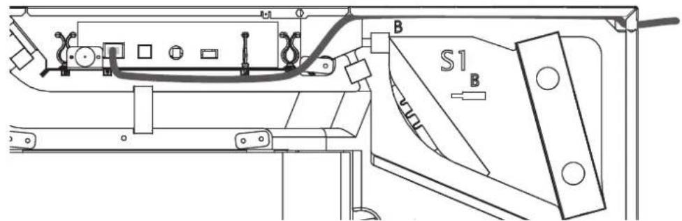
Fig. 24
Connecting to LAN
Connect the unit to LAN using a standard Ethernet cable, fitted with RJ45 plug.
If using non pre-fabricated cable, please first run the cable through the house as needed and mount the RJ45 plug using the standard Ethernet wire crossing terminology, as specified in T568B. These mounting instructions can be found in the internet fx. on Wikipedia.
The unit will be accessible for the smartphone app (IOS and Android), if your device is connected to the same network via WIFI.
| IP adress allocation status | Description |
| Dynamic IP If the unit | is connected to a router with built-in DHCP server it will fetch the IP address itself from the router when the unit starts up. |
| Static IP Using PC Tool | it is possible to allocate a static IP address to the unit, which is necessary for example in order to perform checks on HCC 260/360 via smartphone app when outside the LAN's range. This will also require setup of the home's WAN address as well as allocating a port on the router. |
MODBUS
MODBUS:
MODBUS RTU is only for internal communication between unit (UVC print) and Dantherm accessories (HAC, FPC, or HCP11)
Connected via RS485 port
Important! External BMS can not be connected as a Modbus RTU via RS485 port, nor via Dantherm accesso-ries. (HAC, FPC, or HCP11)
Modbus TCP/IP
The controllers in the Dantherm ventilation units has the possibility to communicate Modbus TCP/IP over the Ethernet port. This is used for Building Management Systems (BMS) or communication with smartphone apps.
Antenna
External antenna can be connected here, to gain higher coverage area.
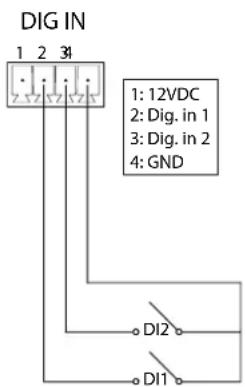
Dig. input
The unit is fitted with 2 overrule inputs, also called digital inputs. These inputs can be used for selecting other fan speed level or activating alarms.
As default the digital input are setup to:
• Dig. input 1: Ventilation step 2
• Dig. input 2: Ventilation step 4
How it works (example to the right):
- Switch DI1 between pin 2 & 4 will activate input 1
- Switch DI2 between pin 3 & 4 will activate input 2
Dig. input can be used for:
• Ventilation steps from 0 - 4
- Safety shutdown
• High water level sensor.
- Kitchen hood boost
- And more
Find relevant information and settings in the PC Tool, under External Control.
Initial calibration
| Introduction | After the installation the unit need to be calibrated to adapt any specific duct system. This is done by connecting a computer with MS Windows, to the USB hidden under a black rubber ceiling, on the front cover, and start up the PC Tool software, specific for this unit type.. | |
| Connect power | The unit is fitted with a 230V Schuko plug. NEVER cut away this plug. The unit needs to have an easy disconnecting possibility., as it needs to be rebooted when doing a firmware upgrade, as well as being disconnected when connecting additional connections. Connect the plug into an 230V socket with earth. | |
| Connect USB | Locate the black rubber bushing, and remove it, to be able to connect the enclosed USB cable, between the unit and your computer. | |
| Calibration | Please follow this procedure to calibrate the unit: | |
| No Action Illustration | ||
| 1 | Make sure the unit is in correct operation mode (A or B) according the duct connection, and assure that correct label is placed on the unit .See more at page 16 | |
| 2 | Locate the air flow chart placed on the front cover of the HCC 260/360. Based on the required air volume for each specific installation, its possible to read out the corresponding pressure drop over the heat exchanger. | |
| 3 | Connect the ΔPa meter across the supply air path, as shown. This example is based on the unit being in operation mode A. Use a football needle pin, punch this all the way through the rubber ceiling pad. When removing the pin, the rubber will close the hole.Needle: | |
| 4 | Adjust the supply fan speed, according the guide in the PC Tool on your computer. The goal is to adjust the fan until the ΔPa meter shows the pressure drop value that was read in point no 2 | |
| 5 | Move the ΔPa meter across theextractair path as shown. This example is based on the unit being in operationmode A. | 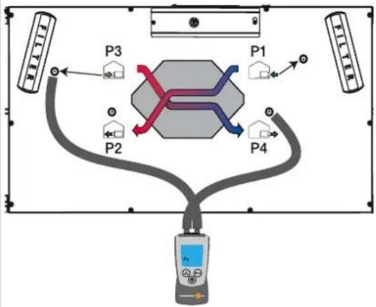 |
| 6 | Adjust theextractfan speed, according the guide in the PC Tool on your computer. The goal is to adjust the fan until the ΔPa meter shows the pressure drop value that was read in point no 2,deducteda few percent,in order to create a small under pressure inside the house. | |
| 7 | Disconnect the ΔPa meter, as well as the computer. Adjust the balancing of the valves in every room in order to make sure that the desired air flow rate can be supplied in every room.Check the nominal air flow rates based on earlier instructions in this procedure, as radical adjustments (balancing) will influence the nominal air flow rates. | |
Operation (user)
Overall ventilation functions
Introduction
Never switch off the main power to shut down the ventilation. This could ultimately result in condensate water dripping from air inlets.
The HCC260/360 unit is able to operate in the ventilation and override modes mentioned in this section. Please be aware, that the different operation modes cannot be activated via the unit itself, but have to be activated via an additional remote control (HCP 10/11 or HRC3) or via the Dantherm Smartphone app.
Ventilation modes
The units can ventilate your home in three different main operation modes. The modes are selectable according personal needs, taking in mind that national rules and regulations, can state a minimum ventilation requirement. Auto mode requires an accessory sensor
| Mode Description | |
| Manual In manual operation, the unit will run in the required fan speed at all times. Fan speed 4 is 130 % boost mode. Deactivates automatically after 4 hours Fan speed 3 is nominal fan speed, defined as 100 % Fan speed 2 is 70 % of speed 3 Fan speed 1 is 49 % of speed 3 Fan speed 0 is fan stop. Deactivates automatically after 4 hours. | |
| Week timer Timer controlled operation mode sets the fan speed according a week time table. The controller has 10 fixed and 1 custom timer. Select a fixed time table that cover your requirements or create a custom timer, in the PC Tool. Appendix A - “Week program specification” on page 41 shows in details, the week programs layout | |
| Demand (RH or VOC sensor needed) | In auto mode (demand), the unit will automatically adjust the ventilation level, to comply with the ventilation needs, measured in the outgoing air by VOC and/or RH% sensors. This operation mode is only possible if the unit is fitted with VOC and/or RH% sensor. |
Override operation
On top of the above main ventilation modes, the user can select some override modes for various purposes. These overrides will disable automatically depending on time or temperature.
| Overrides Description | |
| Fan boost 130% | boost in 4 hours. |
| Summer mode | Supply fan off, extract fan still running, and colder air will flow through any open window. This reduces inside temperature in summer times, with half energy consumption. |
| Bypass (accessory, if not standard equipment) | Both fans running, but no heat recovery. This will automatically supply colder outside air, that reduces inside temperature in summer times. |
| Fireplace booster | 7 min. with extract fan reduced to 50% This creates an overpressure enhancing the chimney function, when lighting a fireplace |
| Night mode Sets | the fan to speed 1 at night regardless of any other mode. Start and end time can be set from the remote control |
| Away mode In Away mode, the unit will run same fan speed as manual fan speed 1. After 28 days or manual disabling of Away mode the unit will run week program mode. | |
User Rights
User Right
This unit is designed for hidden installation. Any user interaction is therefore based on external devices, either a wireless remote control or a smartphone app. See the enclosed manual for these accessories for user instructions.
The PC Tool for installers, brings even more extensive options for installers. This below table shows all controls available on these interfaces
| Function Unit Wired remote | control | Handheld remote control | Smart-phone | PC Tool | ||
| Basic operation HCP 10 HCP 11 | ||||||
| Select Basic operation Mode (Man, Week and Auto if sensor exist) User User User User | ||||||
| Select Fan step 1-4 in manual fan mode User User User - | ||||||
| Select Summer Mode User User User User | ||||||
| Select Fire place boost mode User User User User | ||||||
| Enable away mode -User - | ||||||
| Night mode enable | - | User User - | ||||
| Set start/end night mode | - | User User - | ||||
| Basic readout | ||||||
| Read actual mode | User User User User | |||||
| Read actual fan step | User User User User | |||||
| Read indication if summer mode is active | User User User User | |||||
| Read temperatures for T1-T4 | - | User User User | ||||
| Read temperature for T5 - If wireless remote active | - | User | User | User | ||
| Read supply and extract fan speeds in RPM | - | - | Installer | - | Installer | |
| Filter | ||||||
| Filter fouling - three steps indication | - | User User User | ||||
| Acoustic filter alarm | Yes | - | User | User | ||
| Reset filter timer upon expiration | User - | User User | ||||
| Reset filter timer before expiration | User - | User User | ||||
| Read remaining filter time in days | - | - | - | User | User | |
| Alarms | ||||||
| Acoustic alarm signalling | Yes | - | User | Yes | ||
| Read real time error indication | - | User User User | ||||
| Read specific error code indication | User User User User | |||||
| Read historical error log with timestamps | - | - | - | - | User | |
| Time and Date | ||||||
| Read and set time/date | - | - | User | User | User | |
| Select week program no. | - | - | User | User | User | |
| Set custom settings for week program 11 | - | - | - | - | User | |
| Read power-on time counter | - | - | - | - | User | |
| Read date of installation | - | - | - | - | User | |
| Manual calibration of nominal rpm | ||||||
| Guided in PC Tool | - | Installer | - | - | Installer | |
| Network | ||||||
| Enable DHCP | - | - | - | - | User | |
| Set fixed TCP-IP network address (otherwise automatic using DHCP) | - | - | - | - | User | |
| SW versions | ||||||
| Read MPCB software version | - | - | Installer | - | User | |
| Read wireless remote software version | - | - | Installer | - | - | |
| Read smartphone app software version | - | - | - | User | - | |
| Read PC Tool software version | - | - | - | - | User | |
| Read HAC software version | - | - | Installer | - | - | |
| Forced test of internal preheater and by-pass | ||||||
| Started from PC Tool | - | - | - | - | Installer | |
| External override | ||||||
| Set functionality for digital input | - | - | - | - | Installer | |
| Unit type configuration | ||||||
| Read unit type | - | - | - | - | User | |
| Select unit type | - | - | - | - | Installer | |
| Read and set serial number | - | - | - | - | Installer | |
| Set unit name | - | - | - | - | Installer | |
| Read unit name | - | - | - | User | User | |
| Read A/B switch position | - | - | - | - | User | |
| House settings | ||||||
| Select type private/social -(disable step 0 in social) | - | - | - | - | Installer | |
| Select Isolation of house | - | - | - | - | Installer | |
| Select if Fireplace present (defrost under pressure not allowed) | - | - | - | - | Installer | |
Maintenance and care
Preventative maintenance
Introduction
To keep the unit into specifications, preventive maintenance has to be carried out, with specific intervals to avoid breakdown, inefficient operation and to maximize the expected lifetime, of 10 years or more.
It is important to notice, that intervals between filter maintenance can vary depending on the specific environment. Moving parts are wearing parts, that needs replacements when worn down, dependent on the specific environment.
The factory warranty is only valid if documented preventive maintenance has been carried out. The documentation could be in form of a written log.

WARNING
- Turn off the power supply before applying any work on the unit!
- Only trained and certified technicians are allowed to service the fans. Users are allowed to changes filters only.
- Make sure that all work is finished and the front cover plate is fully mounted before turning on the power supply again.
Scope of maintenance
The following parts needs preventive maintenance:
| Service interval Task To be carried out by: | ||
| 6 month Filter check. | Change if required User | |
| 1 year | Filter replacement User | |
| External condensate discharge Trained engineer | ||
| 2 years | Heat exchanger Trained engineer | |
| Fans Trained engineer | ||
| Drip tray/internal discharge Trained engineer | ||
| Internal air ducts Trained engineer | ||
Replace filters (1 year)
Check or replace filters when the filter alarm sounds, and flashes on the remote control. Always reset the filter timer after a filter replacement. See the remote control manual for more information.
Filter intervals can be adjusted to adapt pollution level in the house, and outdoor air particle content. See how in "User Right" on page 27
Filters must, however, be checked every six months. Dantherm always recommends replacing filters at least once a year. When checking the filters, clean the unit externally around the filter openings with a damp cloth, to maintain good hygiene.
The filters are located behind the small lids, on the front panel
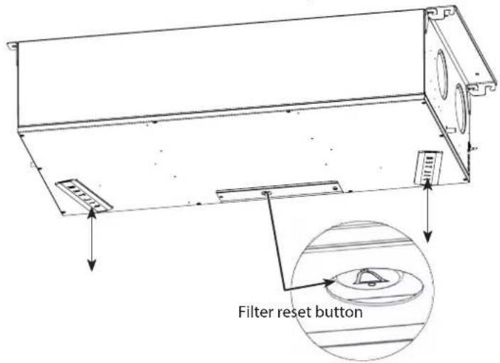
Fig. 25
Drain and hose (1 year)
Drain and hose must be checked every year.
Check that the hose is secured properly to the unit, and that there is water in the water trap. Check that the hose is not wrinkled and that there is a minimum gradient of 1% from the unit to the drain. If the hose is routed to different surrounding temperatures, make sure the hose is protected against frost damages.
Unit dripray (2 year)
Ensure that the condensate drain is not blocked in the drip tray. Clean the drip tray with soapy water and a brush or cloth every other year, to ensure good hygiene inside the unit. Please follow this procedure to clean the drip tray:
| Step Action Illustration | ||
| 1 | Disconnect the 230V AC power supply, and remove the unit cover.See “Fig. 22” on page 21 | |
| 2 | Remove the drainage hoseand turn all shown locks 90° | 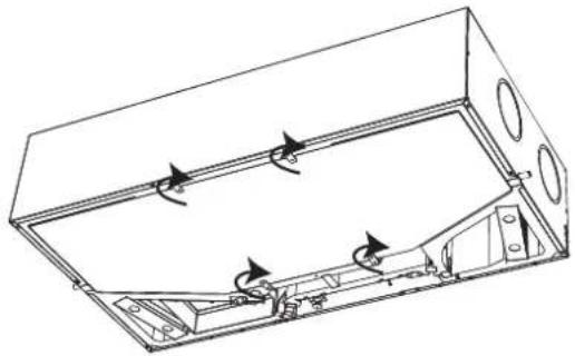 |
| 3 | Gently remove the drip tray.Please be aware, that if theunit is underneath the ceiling, it can contain a smallamount of water. | 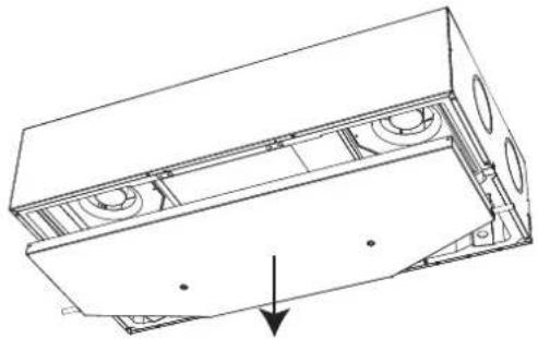 |
| 4 | Clean and re-insert the drip tray (please check fans according below if needed, prior to inserting the drip tray) | |
| 5 | Re-assemble the unit. Check if one water exit is connected, and the opposite drip trayspigot is blocked. | |
Fan
(2 year)
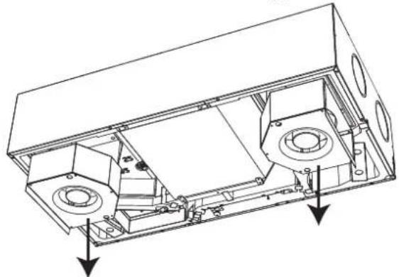
Clean the fan blades every other year using compressed air or a brush. Each fan blade should be clean in order to keep the fan balanced. Gently spin the fans and listen for bearing noise. If so the fan are worn out, and needs to be replaced.
WARNING: Be careful not to remove the metal balancing pieces mounted on the fan blades.
natural_image
Technical line drawing of a mechanical housing or enclosure with internal components and mounting holes (no text or symbols)Fig. 26
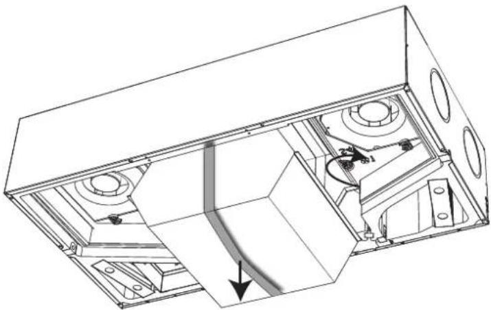
Heat exchanger (2 year)
Check the heat exchanger for dust and dirt every other year. Clean the heat exchanger with a soft brush and a vacuum cleaner at all four inlets. In special cases, e.g. if there are signs of accumulated, dirty condensate in the heat exchanger, it may be necessary to remove the exchanger from the unit and clean the exchanger with soapy water.
Turn the four locks, and the heat exchanger can be removed.
natural_image
Technical line drawing of a mechanical assembly with internal components and a directional arrow (no text or symbols)Fig. 27
Trouble shooting
| Introduction | This section shows how to acknowledge and understand possible operation errors. For a proper error search, Dantherm strongly recommends to have a remote control connected and operative with the unit. | ||
| Error signalling | Any possible error will be displayed on: | ||
| Device Signal | |||
| Unit Acoustic buzzer | signal from the main PCB. Connect a remote or PC Tool, in order to get the specific error shown. | ||
| LED for filter reset | |||
| Handheld remote control | Acoustic buzzer signal as well as displaying a specific error code. | ||
| Wired remote control (HCP 10/11) | Acoustic buzzer signal and flashing LED. The number of flashes corresponds to an error code, followed by a 5 second break. See Error list. | ||
| PC Tool Displaying error number, as well as being able to log specific operations, over a longer time span. | |||
| Smartphone APP Displaying a specific error code. | |||
| Error list | Errors shown on the display, is a three digit information. F. ex. "E12" means error number 12. | ||
| How to read the error list: | |||
| Column Description Code Meaning | |||
| A | Number of flashes in display (Wired control) - - | ||
| B LED | in foil panel | Y Yellow LED flashing | |
| R Red LED flashing | |||
| C Sound | 0 No beep | ||
| 1 One beep/hour | |||
| 2 One beep/sec | |||
| Resetting errors | After completion of any inspection or repair, due to possible errors, the unit can be reset by disconnecting / re-connect the 230V AC power. This will reset the controller, and the unit will start normal operation, and also restart a new search for possible errors. This could last up to 15 minutes. | ||
See below list for a full description:
| A B C | Error code | Fault Possible cause | Action required | Reset | |||
| -Y | 1 | Filter | alarm | Filter period | expired | Unmount filters and examine for dirtChange filters and reset alarm | Reset alarm and reset filter by pressing and holding alarm button for 5 secondsOn wireless remote press and hold center button for 10 secondsSame procedure can be used to reset filter before alarm. |
| Filters are not dirty, so filter period is to short | Extend the filter timer period | ||||||
| Filters are dirty | Change filters and reset alarm | ||||||
| Filters are very dirty, filter period is to long | Change filters and reset alarmShorten the filter timer period | ||||||
| 1 R | 1 E | 1 | Exhaust air fan | No rotation speed (tacho) feedback from the exhaust air fan | Exhaust air fan power cable not connected | Connect Exhaust air fan power cable | Manual reset by pressing alarm button on foil panel or by powering unit off/on |
| Exhaust air fan control cable not connected | Connect Exhaust air fan control cable | ||||||
| Exhaust air fan does not work | Replace Exhaust air fan | ||||||
| Exhaust air fan cannot run the desired RPM | Fan speed setpoint is too high | Lower fan speed setpoint | Automatic reset after 140 seconds, but alarm will appear again if problem is still there | ||||
| Fan is defect Replace fan | |||||||
| 2 R | 1 E | 2 | Supply air fan | No rotation speed (tacho) feedback from the supply air fan | Supply air fan power cable not connected | Connect Supply air fan power cable | Manual reset by pressing alarm button on foil panel or by powering unit off/on |
| Supply air fan control cable not connected | Connect Supply air fan control cable | ||||||
| Supply air fan does not work | Replace Supply air fan | ||||||
| Supply air fan cannot run the desired RPM | Fan speed setpoint is too high | Lower fan speed setpoint | Automatic reset after 140 seconds, but alarm will appear again if problem is still there | ||||
| Fan is defect Replace fan | |||||||
| 3 R | 0 E 3 | By-pass damperdoes not close as expected | Switch position A:Bypass is closed, but supply temperature is lower than expected | Check if bypass is enabled in PC-Tool | Automatic reset if efficiency is high enough for 30 seconds | ||
| Check if bypass is blocked | |||||||
| Check mechanical connection between bypass actuator and bypass valve | |||||||
| Switch position B:Bypass is closed, but exhaust temperature is higher than expected | |||||||
| Check electric connection between controller and bypass | |||||||
| Check controller output | |||||||
| By-pass damperReduced heat recovery due to low extract flow | Dirty extract air filter | Change filters Automatic reset if efficiency is high enough for 30 seconds | |||||
| Poor balancing of the air flows | |||||||
| A bathroom extract fan is creating under-pressure in the house | Remove the extract fan from the bathroom and instead connect the extract air from the bathroom to the ventilation system | ||||||
| A kitchen extract fan is creating under-pressure in the house | Create heated replacement air for the extraction hood. If not possible open a window/door while the extraction hood is running | ||||||
| A stove fan is creating under-pressure in the house | Contact supplier of chimney/stove to secure safety precautions | ||||||
| 3 R | 0 E3 | Bypass is closed,but supply temperature is lower than expected | Dirty supply air filter | Change filters | |||
| Poor balancing of the air flows | Adjust the system | ||||||
| 4 R | 1 E 4 | Extract air | temperature sensor (T1) | Temperature sensors are not mounted correct | Mount temperature sensors correct | Automatic reset if temperature is within normal range for 30 seconds | |
| Control board measure that temperature sensor is either open or shortcut circuit | Resistance in one of the temperature sensors is too low or too high | Change temperature sensors | |||||
| Resistance in temperature sensors are OK | Change control board | ||||||
| 5 R | 1 E 5 | Supply air | temperature sensor (T2) | Temperature sensors are not mounted correct | Mount temperature sensors correct | Automatic reset if temperature is within normal range for 30 seconds | |
| Control board measure that temperature sensor is either open or shortcut circuit | Resistance in one of the temperature sensors is too low or too high | Change temperature sensors | |||||
| Resistance in temperature sensors are OK | Change control board | ||||||
| 6 R | 1 E 6 | Extract air | temperature sensor (T3) | Temperature sensors are not mounted correct | Mount temperature sensors correct | Automatic reset if temperature is within normal range for 30 seconds | |
| Control board measure that temperature sensor is either open or shortcut circuit | Resistance in one of the temperature sensors is too low or too high | Change temperature sensors | |||||
| Resistance in temperature sensors are OK | Change control board | ||||||
| 7 R | 1 E 7 | Exhaust air | temperature sensor (T4) | Temperature sensors are not mounted correct | Mount temperature sensors correct | Automatic reset if temperature is within normal range for 30 seconds | |
| Control board measure that temperature sensor is either open or shortcut circuit | Resistance in one of the temperature sensors is too low or too high. | Change temperature sensors | |||||
| Resistance in temperature sensors are OK | Change control board | ||||||
| 8 - 0 E 8 | Room air | temperature sensor (T5) | Only shown on wireless remote Automatic reset | ||||
| 9 - - E 9 Not used | |||||||
| 10 | R 0 E | 10 | Outdoor | temperature < -13 °C | -- Automatic re- | start after 1800 seconds | |
| 11 | R 0 E | 11 | Supply | temperature < +5 °CReduced heat recovery due to low extract air temperature | Low temperatures extracted from nonheated rooms | Ensure heating in all ventilated roomsAlternatively, close the vents to rooms, which are not heated | Manual reset by pressing alarm button on foil panel or by po-wering unit off/onFirmware version 2.9 and up, also has automatic restart after 600 seconds |
| Poor insulated ducts in cold environments | Improve insulation of ducts | ||||||
| Reduced heat recovery due to low extract flow | Dirty extract air filter | Change filters | |||||
| Poor balancing of the air flows | Adjust the system | ||||||
| A bathroom extract fan is creating under-pressure in the house | Remove the extract fan from the bath-room and instead connect the extract air from the bath-room to the ventilation system | ||||||
| A kitchen extract fan is creating under-pressure in the house | Create heated replacement air for the extraction hood.If not possible open a window/door while the extraction hood is running | ||||||
| A stove fan is creating under-pressure in the house | Contact supplier of chimney/stove to secure safety precautions | ||||||
| 12 | R 2 E | 12 | Overheating | Any one of the internal sensors, is measuring a temperature >70 °C. | Overtemperature caused by fire in- or outside the ventilation unit | Check ventilation unit and surroundings for fire | Alarm display can be reset by pressing alarm button or by powering unit off/on.However unit cannot start before conditions for alarm has disappeared |
| Overtemperature caused by the combination of a pre- or afterheater and too low airflow | Check ventilation unit and surroundings for fire | ||||||
| Check which sensor is measuring a high temperature. Check for blocked air flow and dirty filters.If necessary, raise minimum air flow setting | |||||||
| 13 | -0 E | 13 | Communication error / low signalOnly shown on wireless remote | Retry is every 5 minutes or if a button is pressed | |||
| No wireless signal | Ventilation unit is powered off | Power on the ventilation unit | |||||
| Wireless signal is too weak | Antenna not mounted on unit | Mount antenna | |||||
| Remote is too far away from the ventilation unit | Move closer to the ventilation unit | ||||||
| Mount antenna extension cable | |||||||
| 14 | R 2 E | 14 | Fire alarm | Duct connected fire thermostat (Accessory)Input is normally closed (NC), but now it is open | Fire or smoke sensor connected to this input is active | Check for smoke or fire | Alarm display can be reset by pressing alarm button or by powering unit off/on.However unit cannot start before conditions for alarm has disappeared |
| Check if sensor and connection is OK | |||||||
| Nothing connected to this input | Mount short circuit accessory | ||||||
| 15 | R 1 E | 15 High water level (Accessory) | Water level is too high | The water drain is clogged | Clean the water drain | Automatic reset when input is closed again | |
| The water drain is mounted wrong | Check that water drain is mounted in the correct side and piping is not above level of the drain. | ||||||
| Auxiliary drain pump not running. | Check pump | ||||||
| Check fuse | |||||||
| Water level is not too high | Water level sensor disconnected | Check wiring | |||||
| Water level sensor is Normally Open (NO) | Configure or change water level sensor so it is Normally Closed (NC). | ||||||
| Digital input configured wrong | Check configuration of digital input using PC-Tool | ||||||
| 16 | R 2 E | 16 Firmware | 2.9 and up: FPC Fail (accessory) Only active if the accessory "Fire Protection Controller" is connected to the unit. No communication with Fire Protection Controller | Manual reset by pressing alarm button on foil panel or by powering unit off/on | |||
| Fire Protection Controller with this address has previously been installed but is no longer reachable | Check connection to Fire Protection Controller | ||||||
| A position feedback for a Fire damper is missing | A firedamper is closed but should be open | Check powersupply for the firedamper | |||||
| Check the fire-dampers internal firedetector | |||||||
| Failure at monthly-, weekly- or manual fire damper test | Fire damper is stuck in either open or closed position | Something is blocking the fire damper. | |||||
| Fire damper is connected wrong | |||||||
| Fire damper is defect | |||||||
Appendix
Technical data
Introduction
This table shows the technical data.
| SPECIFICATION Abbr. Unit HCC 360 | HCC 260 | HCC 360 | |||
| P2 | P1 | E1 | |||
| Max. nominel flow V m3/h 220 180 180 | |||||
| Operating range DIBt VDIBt m3/h - 70 to 140 - | |||||
| Operating range Passivhaus @100Pa VPHI | m3/h | -50 to 180 - | |||
| EN 13141-7 reference flow @50Pa | Vref | m3/h | 154 | 126 | 126 |
| PERFORMANCE | |||||
| Thermal efficiency DIBt | ηDIBt | % | - | 93,8 | - |
| Thermal efficiency Passiv Haus | ηPHI | % | - | 93 | - |
| Thermal efficiency EN 13141-7 @ reference flow | ηEN % 88 | 94 | 80 | ||
| Cabinet sound power level @ reference flow | Lw(A) | dB(A) | 40 | 45 | 46 |
| Duct sound power level (supply/extract) @ 140 m3/h & 100Pa | Lw(A) | dB(A) | 58/44 60/45 61/43 | ||
| Filters according to EN779:2012 | class | - | ISO Coarse (ePM1 optional on supply) | ||
| Filters according to ISO 16890 | class | - | ISO Coarse (ePM1>50% optional on supply) | ||
| Installation surrounding temperature range | tSURR | °C | +12 to +40 | ||
| Maximum humidity in extract air @25°C RH | % | 55 | |||
| Outdoor temperature range (without preheating installed)* | tODA | °C | -12 to +45 | ||
| Outdoor temperature range (with preheating installed) | tODA | °C | -15 to +45 | ||
| CABINET | |||||
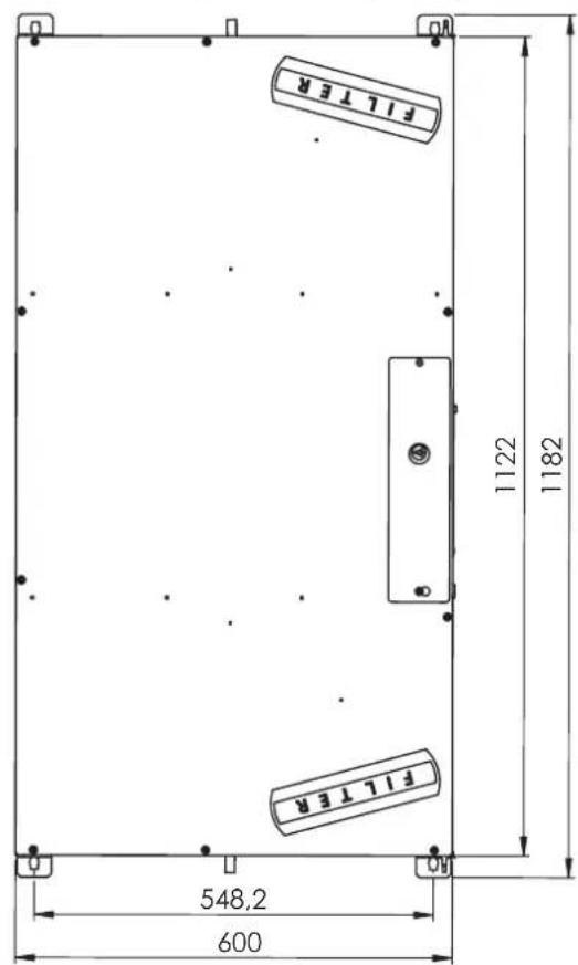
| Dimensions (without bracket) | WxHxD | mm | 600 x 1122 x 279 | ||
| Spigots / Duct connections | ∅ | mm | ∅125 - female | ||
| Weight | m | kg | 34 | ||
| Heat conductivity of the polystyrene insulation | λ W/(mK) | 0,031 | |||
| Heat transfer coefficient of the polystyrene insulation | U W/(m2K) | U<1 | |||
| Leakage (external and internal) according to EN 13141-7 | <2% (Class A1) | ||||
| Drainage hose (Accessory) | ∅ | 1/2" | |||
| Cabinet colour | RAL | - | no paint/raw Alu-zinc | ||
| Fire classification of polystyrene insulation according to DIN 4102-1 | class | - | B2 | ||
| Fire classification of polystyrene insulation according to EN 13501-1 | class | - | E | ||
| ELECTRICAL | |||||
| Voltage | U | V | 230 | ||
| Max. power consumption (without/with preheater) | P | W | 161 / 1061 | 127 / 1027 | 161 / 1061 |
| Frequency | f | Hz | 50 | ||
| IP-class | class | - | 20 | ||
* In order to ensure balanced ventilation, preheater is recommended when outdoor temperature is below -5 degrees.
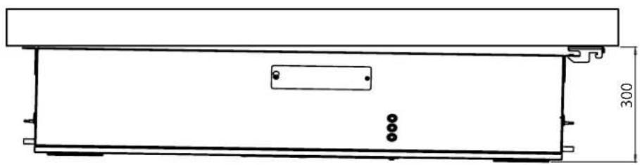
Enclosure dimensions
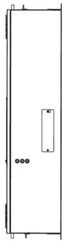
Dimension illustration
This illustrates the dimensions of the unit:
natural_image
Simple line drawing of a door frame with three circular indentations on the front panel (no text or symbols)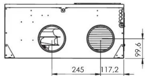
natural_image
Technical line drawing of a rectangular enclosure with a horizontal base and vertical wall, showing dimension 300 (no text or symbols)Schematics
Unit schematics
This illustration shows the PCB with unit connections :
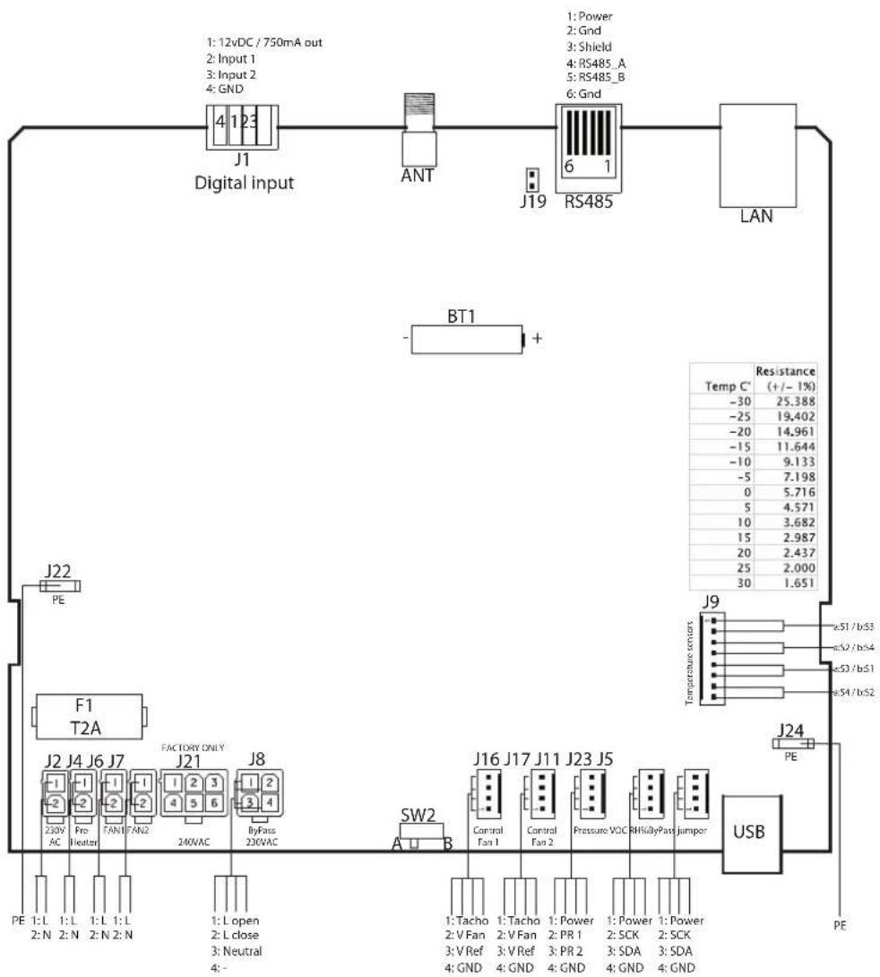
Fig. 28
Week program specification
Program 1

bar
| Weekdays | Value | |---|---| | 1 | 2 | | 2 | 2 | | 3 | 2 | | 4 | 2 | | 5 | 2 | | 6 | 3 | | 7 | 3 | | 8 | 3 | | 9 | 3 | | 10 | 1 | | 11 | 1 | | 12 | 1 | | 13 | 1 | | 14 | 1 | | 15 | 3 | | 16 | 3 | | 17 | 3 | | 18 | 3 | | 19 | 3 | | 20 | 3 | | 21 | 3 | | 22 | 2 | | 23 | 2 | Weekdays (X-axis) are labeled numerically from 1 to 24.
bar
| Weekend | Value | | :--- | :--- | | 1 | 2 | | 2 | 2 | | 3 | 2 | | 4 | 2 | | 5 | 2 | | 6 | 2 | | 7 | 3 | | 8 | 3 | | 9 | 3 | | 10 | 3 | | 11 | 3 | | 12 | 3 | | 13 | 3 | | 14 | 3 | | 15 | 3 | | 16 | 3 | | 17 | 3 | | 18 | 3 | | 19 | 3 | | 20 | 3 | | 21 | 2 | | 22 | 2 | WeekendProgram 2

bar
| Weekdays | Value | | :--- | :--- | | 0 | 2 | | 1 | 2 | | 2 | 2 | | 3 | 2 | | 4 | 2 | | 5 | 3 | | 6 | 3 | | 7 | 3 | | 8 | 3 | | 9 | 3 | | 10 | 1 | | 11 | 1 | | 12 | 2 | | 13 | 1 | | 14 | 1 | | 15 | 3 | | 16 | 3 | | 17 | 3 | | 18 | 3 | | 19 | 3 | | 20 | 3 | | 21 | 3 | | 22 | 3 | | 23 | 2 | | 24 | 2 |
bar
| Weekend | Value | | :--- | :--- | | 1 | 2 | | 2 | 2 | | 3 | 2 | | 4 | 2 | | 5 | 2 | | 6 | 2 | | 7 | 3 | | 8 | 3 | | 9 | 3 | | 10 | 3 | | 11 | 3 | | 12 | 3 | | 13 | 3 | | 14 | 3 | | 15 | 3 | | 16 | 3 | | 17 | 3 | | 18 | 3 | | 19 | 3 | | 20 | 3 | | 21 | 2 | | 22 | 2 | | 23 | 2 | | 24 | 2 |Program 3

line
| Weekdays | Value | | :--- | :--- | | 1 | 2 | | 2 | 2 | | 3 | 2 | | 4 | 2 | | 5 | 2 | | 6 | 3 | | 7 | 3 | | 8 | 3 | | 9 | 3 | | 10 | 3 | | 11 | 3 | | 12 | 3 | | 13 | 3 | | 14 | 3 | | 15 | 3 | | 16 | 3 | | 17 | 3 | | 18 | 3 | | 19 | 3 | | 20 | 3 | | 21 | 3 | | 22 | 2 | | 23 | 2 | Weekdays (labeled) are the same as the number of days in the middle of the chart. The numbers inside the bars represent the count of occurrences for each week.
bar
| Weekend | Value | |---|---| | 1 | 2 | | 2 | 2 | | 3 | 2 | | 4 | 2 | | 5 | 2 | | 6 | 2 | | 7 | 3 | | 8 | 3 | | 9 | 3 | | 10 | 3 | | 11 | 3 | | 12 | 3 | | 13 | 3 | | 14 | 3 | | 15 | 3 | | 16 | 3 | | 17 | 3 | | 18 | 3 | | 19 | 3 | | 20 | 3 | | 21 | 2 | | 22 | 2 | | 23 | 2 | | 24 | 2 |Program 4

line
| Weekdays | Value | |---|---| | 1 | 1 | | 2 | 1 | | 3 | 1 | | 4 | 1 | | 5 | 1 | | 6 | 2 | | 7 | 2 | | 8 | 2 | | 9 | 2 | | 10 | 1 | | 11 | 1 | | 12 | 1 | | 13 | 1 | | 14 | 1 | | 15 | 2 | | 16 | 2 | | 17 | 2 | | 18 | 2 | | 19 | 2 | | 20 | 2 | | 21 | 2 | | 22 | 2 | | 23 | 1 | | 24 | 1 |
Program 5

line
| Weekdays | Value | | :--- | :--- | | 1 | 1 | | 2 | 1 | | 3 | 1 | | 4 | 1 | | 5 | 1 | | 6 | 2 | | 7 | 2 | | 8 | 2 | | 9 | 2 | | 10 | 2 | | 11 | 2 | | 12 | 2 | | 13 | 2 | | 14 | 2 | | 15 | 2 | | 16 | 2 | | 17 | 2 | | 18 | 2 | | 19 | 2 | | 20 | 2 | | 21 | 1 | | 22 | 1 | Weekdays (end) | 1 |Weekend

Program 6
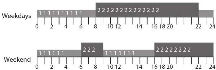
Program 7
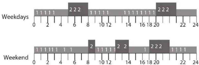
bar
| Day | Weekday | Weekend | | -------- | ------- | ------- | | 1 | 1 | 1 | | 2 | 1 | 1 | | 3 | 1 | 1 | | 4 | 1 | 1 | | 5 | 1 | 1 | | 6 | 2 | 2 | | 7 | 2 | 2 | | 8 | 2 | 2 | | 9 | 1 | 1 | | 10 | 1 | 1 | | 11 | 1 | 1 | | 12 | 1 | 1 | | 13 | 1 | 2 | | 14 | 1 | 2 | | 15 | 1 | 1 | | 16 | 1 | 1 | | 17 | 1 | 1 | | 18 | 1 | 2 | | 19 | 1 | 2 | | 20 | 2 | 2 | | 21 | 2 | 2 | | 22 | 2 | 1 | | 23 | 2 | 1 | | 24 | 2 | 1 |Program 8
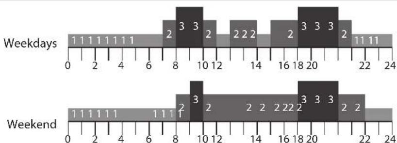
bar
| Day | Weekday | Weekend | |---|---|---| | 1 | 0 | 0 | | 2 | 0 | 0 | | 3 | 0 | 0 | | 4 | 0 | 0 | | 5 | 0 | 0 | | 6 | 0 | 0 | | 7 | 8 | 8 | | 8 | 3 | 8 | | 9 | 3 | 9 | | 10 | 2 | 10 | | 11 | 2 | 11 | | 12 | 2 | 12 | | 13 | 2 | 13 | | 14 | 2 | 14 | | 15 | 2 | 15 | | 16 | 2 | 16 | | 17 | 3 | 17 | | 18 | 3 | 18 | | 19 | 3 | 19 | | 20 | 3 | 20 | | 21 | 2 | 21 | | 22 | 11 | 22 | | 23 | 11 | 23 | | 24 | 11 | 24 |Program 9
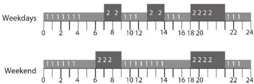
bar
| Day | Time | Value | |---|---|---| | Weekdays | 0 | 1 1 1 1 1 1 1 | | Weekdays | 2 | 2 | | Weekdays | 8 | 2 2 | | Weekdays | 10 | 1 1 1 | | Weekdays | 12 | 1 1 1 | | Weekdays | 14 | 2 2 | | Weekdays | 16 | 1 1 1 | | Weekdays | 18 | 2 2 2 2 | | Weekdays | 20 | 2 2 2 2 | | Weekdays | 22 | 1 1 1 | | Weekdays | 24 | 1 1 1 | | Weekend | 0 | 1 1 1 1 1 1 | | Weekend | 2 | 2 2 | | Weekend | 8 | 2 2 | | Weekend | 10 | 1 1 1 | | Weekend | 12 | 1 1 1 | | Weekend | 14 | 1 1 1 | | Weekend | 16 | 2 2 | | Weekend | 18 | 2 2 | | Weekend | 20 | 2 2 | | Weekend | 22 | 1 1 1 | | Weekend | 24 | 1 1 1 |Program 10
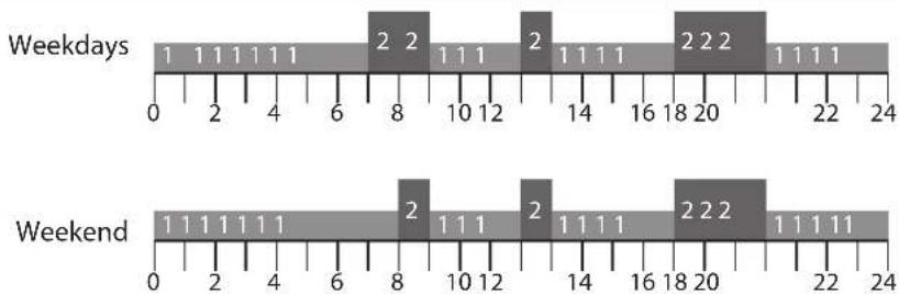
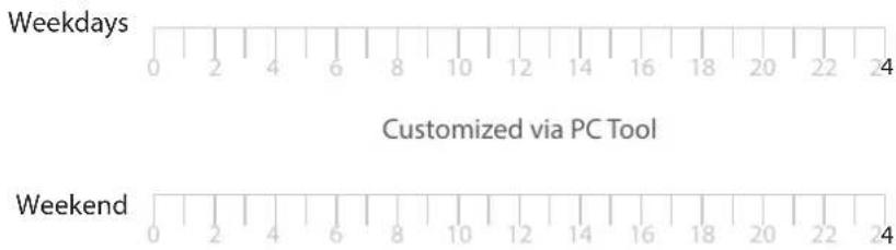
Program 11
Spare parts
Spare parts, where to find
If the need for spare parts occurs, please visit Dantherms webshop: shop.dantherm.com:
- Introduction
- Table of contents
- Declaration of conformity
- Product description
- Overall description
- Product illustration
- Part description
- Airflows
- Sensor placement
- Installation
- General location requirements
- Location and duct connections
- Reserve additional space
- Service space, ceiling
- No Description
- Service space, wall
- Installation options
- Vertical or horizontal
- NOTICE
- Cable routing
- Selecting mode A or B
- WARNING
- Swapping to mode B
- Mounting
- Multi purpose mounting bracket
- Wall mounting
- Under ceiling installation
- Connect duct system
- Secure ducts
- Drainage consideration
- Condensate drainage
- Connecting additional equipment
- Cable installation
- Connecting to LAN
- MODBUS
- Antenna
- Dig. input
- Operation (user)
- Overall ventilation functions
- Ventilation modes
- Override operation
- User Rights
- User Right
- Maintenance and care
- Preventative maintenance
- Scope of maintenance
- Replace filters (1 year)
- Drain and hose (1 year)
- Unit dripray (2 year)
- Fan
- (2 year)
- Heat exchanger (2 year)
- Appendix
- Technical data
- Enclosure dimensions
- Schematics
- Unit schematics
- Week program specification
- Spare parts
Brand : Dantherm
Model : HCC 360P2
Category : Uncategorized