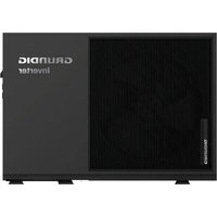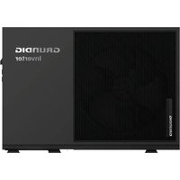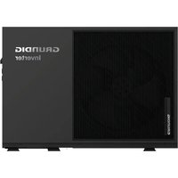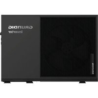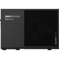
GHP MM8 - Heat pump GRUNDIG - Free user manual and instructions
Find the device manual for free GHP MM8 GRUNDIG in PDF.


User questions about GHP MM8 GRUNDIG
0 question about this device. Answer the ones you know or ask your own.
Ask a new question about this device
Download the instructions for your Heat pump in PDF format for free! Find your manual GHP MM8 - GRUNDIG and take your electronic device back in hand. On this page are published all the documents necessary for the use of your device. GHP MM8 by GRUNDIG.
USER MANUAL GHP MM8 GRUNDIG
text_image
Diagram showing a thermometer symbol inside a door, with a minus sign and a minus sign on the door.GHP-MM08
GHP-MM10
GHP-MM12
GHP-MM14
GHP-MM16
EN
CE
01M-8508043600-2422-01
01M-8508053600-2422-01
01M-8508063600-2422-01
01M-8503073600-2422-01
01M-8503083600-2422-01
Please read this user manual first!
Dear Valued Customer,
Thank you for preferring this Grundig appliance. We hope that you get the best results from your appliance which has been manufactured with high quality and state-of-the-art technology. For this reason, please read this entire user manual and all other accompanying documents carefully before using the appliance and keep it as a reference for future use. If you handover the appliance to someone else, give the user manual as well. Follow the instructions by paying attention to all the information and warnings in the user manual. Remember that this user manual may also apply to other models. Differences between models are explicitly described in the manual.
Meanings of the Symbols
Following symbols are used in various sections of this user manual:

Important information or useful hints about usage.

Warning for hazardous situations with regard to life and property.

Warning to actions that must never perform.
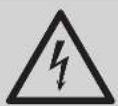
Warning for electric shock.
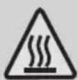
Warning for hot surfaces.

Do not cover it.

This symbol shows that the operation manual should be read carefully.
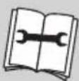
This symbol shows that a service personnel should be handling this equipment with reference to the installation manual.

text_image
Warning sign depicting a flame symbol in a triangular shape(For R32/R290 gas type)
This symbol shows that this appliance used a flammable refrigerant. If the refrigerant is leaked and exposed to an external ignition source, there is a risk of fire.
Table of Contents
Part 1 General Features ....4
1.1 Unit Capacities and Appearance 4
Part 2 Component Layout and Refrigerant Circuit....5
2.1 Layout of Functional Components....5
2.2 Piping Diagram....8
2.3 Refrigerant Flow Diagram 10
Part 3 Control....11
3.1 Stop Operation....11
3.2 Standby Control 11
3.3 Startup Control .... 11
3.4 Normal Operation Control 13
3.5 Protection Control ....13
3.6 Special Control....14
3.7 Role of Temperature Sensors in Control Functions 16
3.8 EEPROM Parameter Setting 20
3.9 Electric Wiring Diagram 26
Part 4 Troubleshooting ....30
4.1 Unit Electric Control Box Layout 30
4.2 Unit PCBs....33
4.3 Error Code Table 39
4.4 Troubleshooting....41
4.5 Appendixes to Part 4....80
Part 1 General Features
1.1 Unit Capacities and Appearance
1.1.1 Unit Capacities
Table 1-1.1: Capacity range
| Factory Model | KS-80W/EN8BP | KS-100W/EN8BP | KS-120W/EN8BP | KS-140W/EN8BP | KS-160W/EN8BP |
| Model No. | GHP-MM 08 | GHP-MM 10 | GHP-MM 12 | GHP-MM 14 | GHP-MM 16 |
Notes:
- The full model names can be obtained by substituting the asterisk in the model name format given in the left-hand column of the table above with the shortened model names given in the table. For example, the model name for the 14kW model is GHP-MM14.
- The presence or omission of the letter E and S in the model names indicates:
E: with internal backup heater; omitted: without internal backup heater.
- Power supply:
220-240V, 50Hz, 1-phase.
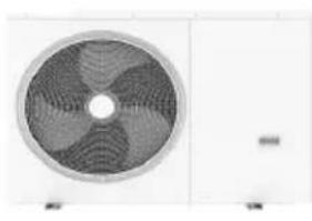
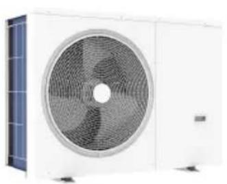
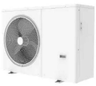
1.1.2 Appearance
Table 1-1.2: Unit appearance
| 8kW |
 |
| 10/12kW 14/16kW | |
 |  |
Part 2 Component Layout and Refrigerant Circuit
2.1 Layout of Functional Components
GHP-MM08
Figure 2-1.1: top view
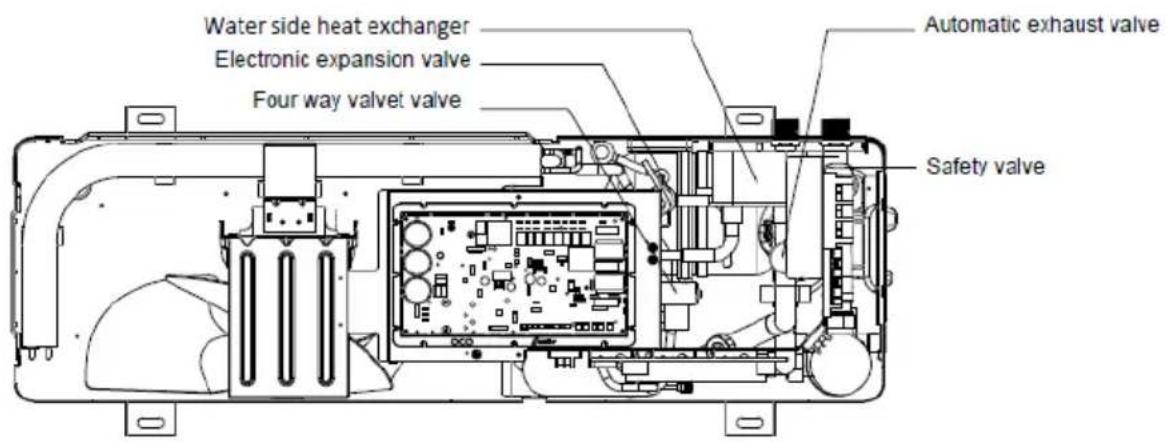
text_image
Water side heat exchanger Electronic expansion valve Four way valvet valve Automatic exhaust valve Safety valveFigure 2-1.2: front view
text_image
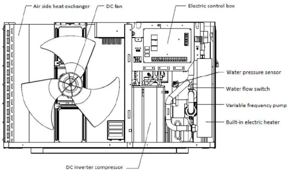
Air side heat exchanger DC fan Electric control box Water pressure sensor Water flow switch Variable frequency pump Built-in electric heater DC inverter compressorFigure 2-1.3: top view
text_image
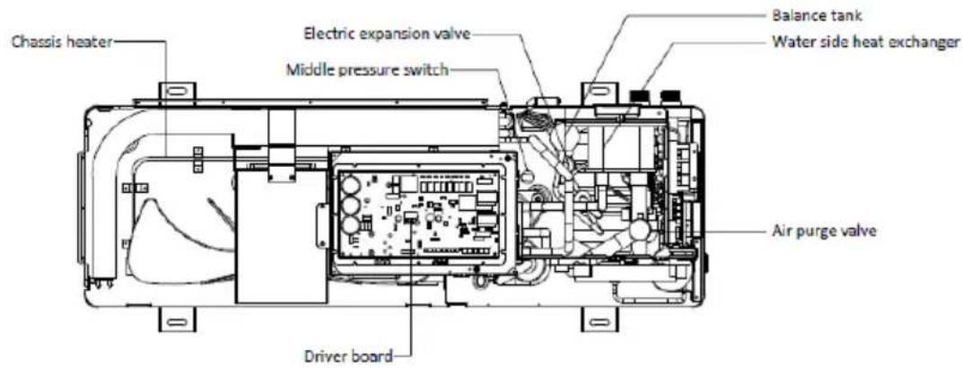
Chassis heater Electric expansion valve Middle pressure switch Balance tank Water side heat exchanger Air purge valve Driver boardFigure 2-1.4: front view
text_image
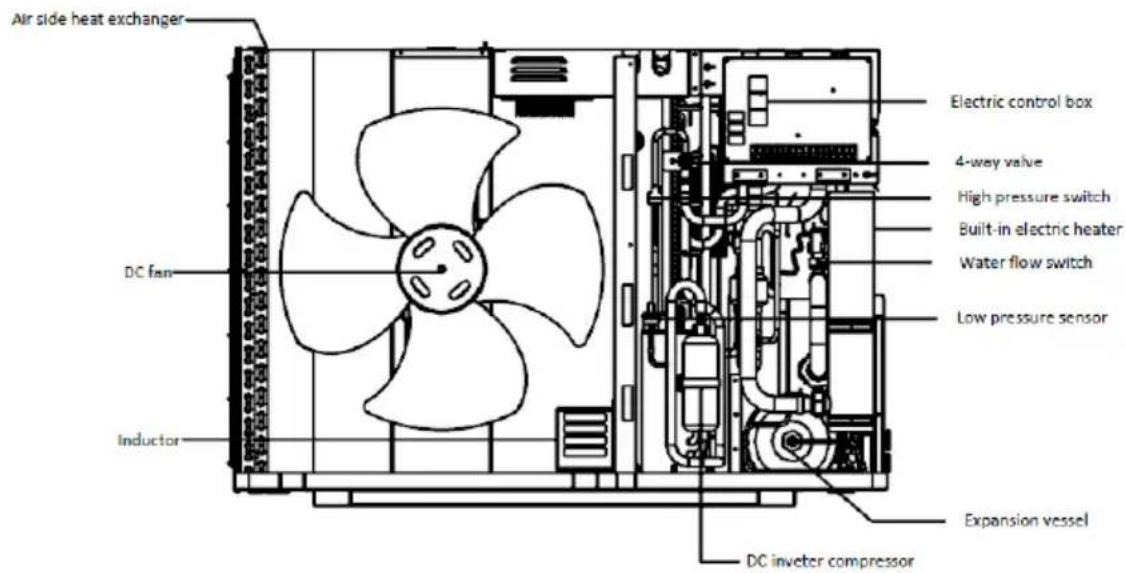
Air side heat exchanger DC fan Inductor Electric control box 4-way valve High pressure switch Built-in electric heater Water flow switch Low pressure sensor Expansion vessel DC inveter compressorGHP-MM12
Figure 2-1.5: top view
text_image
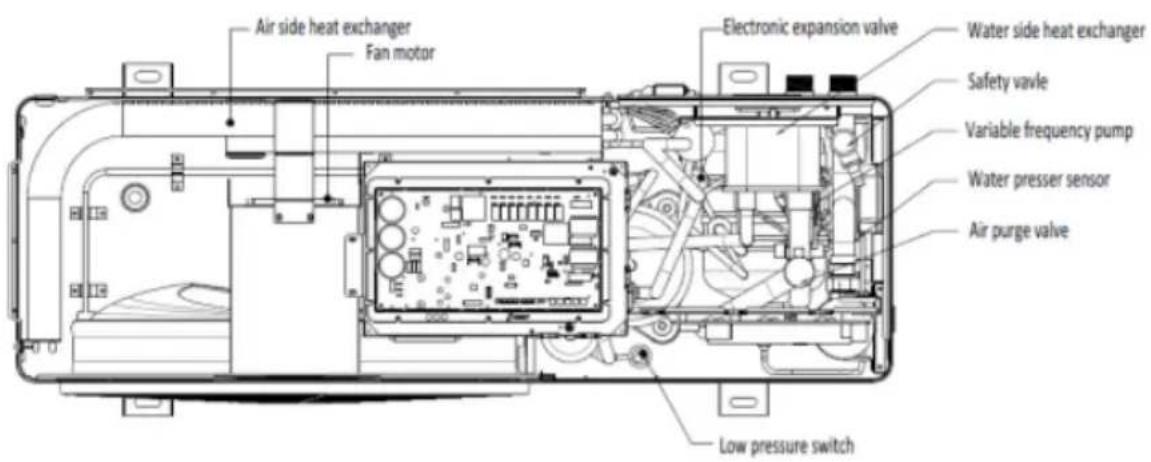
Air side heat exchanger Fan motor Electronic expansion valve Water side heat exchanger Safety valve Variable frequency pump Water presser sensor Air purge valve Low pressure switchFigure 2-1.6: front view
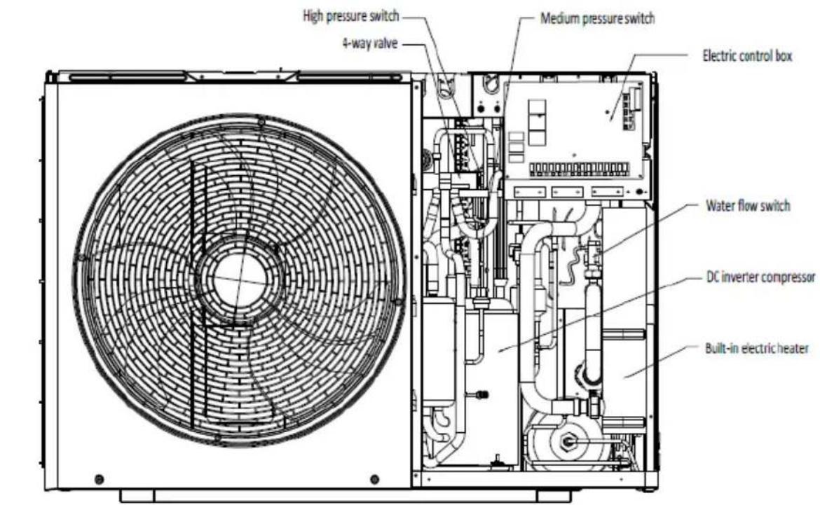
text_image
High pressure switch 4-way valve Medium pressure switch Electric control box Water flow switch DC inverter compressor Built-in electric heaterGHP-MM14/ GHP-MM16
Figure 2-1.7: top view
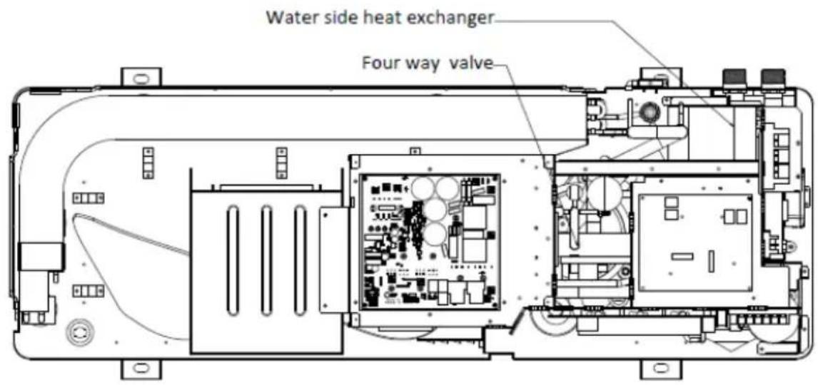
text_image
Water side heat exchanger Four way valveFigure 2-1.8: front view

text_image
Air side heat exchanger Fan motor Electric control box Built-in electric heater Electronic expansion valve Water flow switch DC inverter compressor2.2 Piping Diagram
Figure 2-2.1: Piping diagram
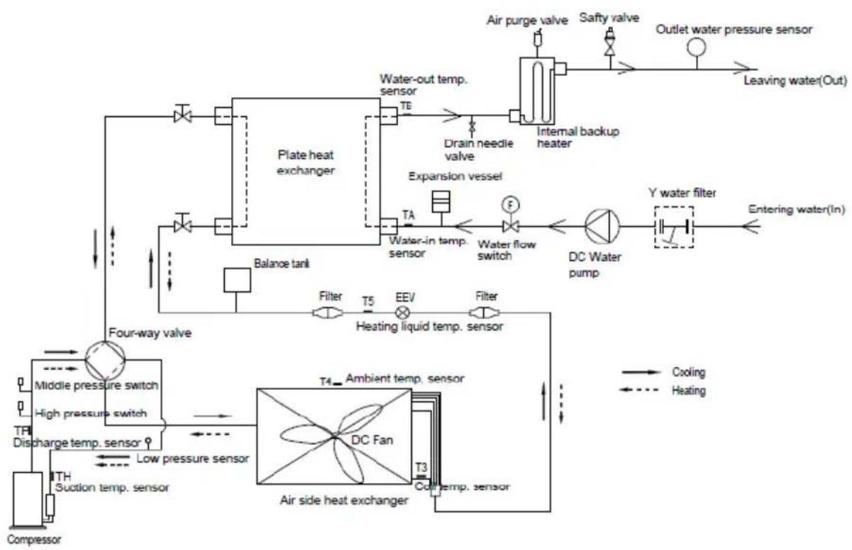
Compress low temperature and low pressure refrigerant gas into high temperature and high pressure refrigerant gas.
2. Electronic expansion valve (EEV)
Control refrigerant flow and reduce refrigerant pressure.
3. 4-way valve
Control refrigerant flow direction. Open in cooling mode and closed in heating mode. When open, the air side heat exchanger functions as a condenser and water side heat exchanger functions as an evaporator; when closed, the air side heat exchanger functions as an evaporator and water side heat exchanger functions as a condenser.
4. High and middle pressure switch
Regulate refrigerant system pressure. When refrigerant system pressure rises above the upper limit, the high or middle pressure switches will open and then turn off heat pump.
5. Low pressure sensor
Regulate refrigerant system pressure. When refrigerant system pressure falls below the lower limit, low pressure sensor detects the limit value and then turns off heat pump.
6. Air purge valve
Automatically remove air from the water circuit.
7. Safety valve
Preventing excessive water pressure by opening at 43.5 psi (3 bar) and discharging water from the water circuit.
8. Expansion vessel
Balance water system pressure. (Expansion vessel volume: 5L)
9. Water flow switch
Detect water flow rate to protect compressor and water pump in the event of insufficient water flow.
10. Backup heater
Provide additional heating capacity when the heating capacity of the heat pump is insufficient due to very low outdoor temperature. Also protects the external water piping from freezing.
11. Internal water pump
Circulate water in the water circuit.
2.3 Refrigerant Flow Diagram
Heating and domestic hot water operation (8,16KW for example)
Figure 2-3.1: Refrigerant flow during heating or domestic hot water operation
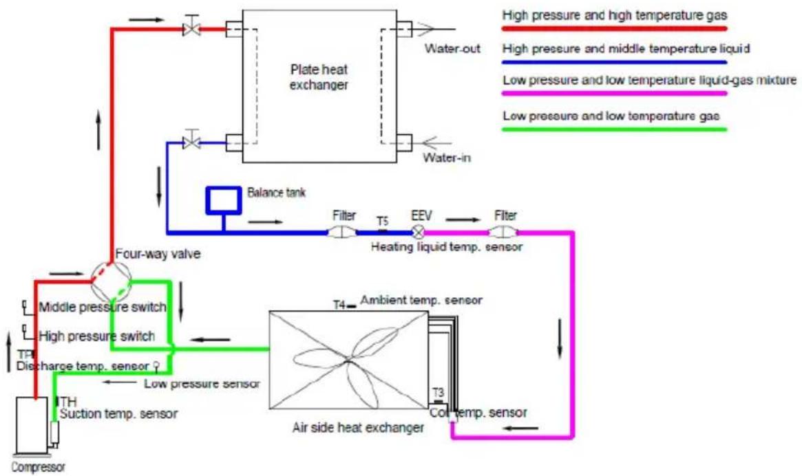
flowchart
graph TD
    A["Compressor"] --> B["TH Suction temp. sensor"]
    B --> C["Low pressure sensor"]
    C --> D["Discharge temp. sensor"]
    D --> E["TPI"]
    E --> F["Middle pressure switch"]
    F --> G["Four-way valve"]
    G --> H["Balance tank"]
    H --> I["Plate heat exchanger"]
    I --> J["Water-in"]
    J --> K["Water-out"]
    K --> L["High pressure and high temperature gas"]
    K --> M["High pressure and middle temperature liquid"]
    K --> N["Low pressure and low temperature liquid-gas mixture"]
    K --> O["Low pressure and low temperature gas"]
    P["Air side heat exchanger"] --> Q["T3"]
    Q --> R["Contemp. sensor"]
    R --> S["T4"]
    S --> T["Ambient temp. sensor"]
    T --> U["Heating liquid temp. sensor"]
    U --> V["Filter"]
    V --> W["Filter"]
    W --> X["EEV"]
    X --> Y["T5"]
    Y --> Z["Balance tank"]
    Z --> AA["Water-in"]
    AA --> AB["Plate heat exchanger"]
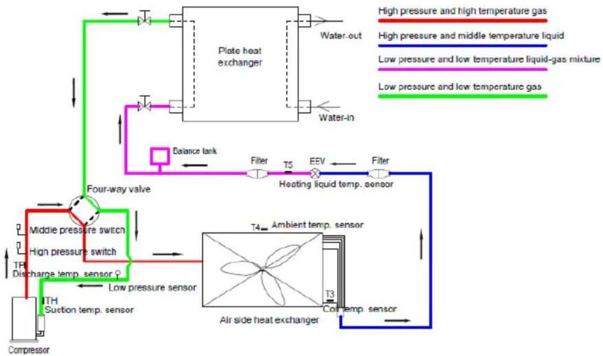
Cooling and defrosting operation (8,16KW for example)
Figure 2-3.2: Refrigerant flow during cooling and defrosting operations
flowchart
graph TD
    A["Compressor"] --> B["TH Discharge temp. sensor"]
    B --> C["High pressure switch"]
    C --> D["Middle pressure switch"]
    D --> E["Four-way valve"]
    E --> F["Plate heat exchanger"]
    F --> G["Water-out"]
    F --> H["Water-in"]
    F --> I["Balance tank"]
    I --> J["Filter"]
    J --> K["T5"]
    K --> L["EEV"]
    L --> M["Heating liquid temp. sensor"]
    M --> N["Filter"]
    N --> O["T4 Ambient temp. sensor"]
    O --> P["Air side heat exchanger"]
    P --> Q["T3 Con temp. sensor"]
    Q --> R["Low pressure sensor"]
    R --> S["Low pressure and low temperature gas mixture"]
    style A fill:#f9f,stroke:#333
    style P fill:#ccf,stroke:#333
Part 3 Control
3.1 Stop Operation
The stop operation occurs for one of the following reasons:
3.1.1 Normal shutdown: The heat pump will stop running when the set temperature has been reached.
3.1.2 Abnormal shutdown: in order to protect the compressors, if an abnormal state occurs the system makes a "turn off" operation and an error code are displayed on the user interface.
3.2 Standby Control
3.2.1 Water Pump Control
When the outdoor unit is on standby, the internal and external circulator pumps run continuously.
3.2.2 Crankcase Heater Control
The crankcase heater is used to prevent refrigerant from mixing with compressor oil when the compressors are stopped. The crankcase heater is controlled according to outdoor ambient temperature and the compressor's on/off state. When the outdoor ambient temperature is at or above 7°C or the compressor is running, the crankcase heater is off; when the outdoor ambient temperature is below 5°C and the unit has just been powered on (either manually or when the power supply has been restored from a breakdown), the crankcase heater turns on and run by half an hour on half an hour off cycle. When the compressor has been stopped for more than 3 hours and the outdoor ambient temperature is below 5°C, the crankcase heater turns on and run for half an hour on half an hour off cycle.
3.3 Startup Control
3.3.1 Compressor Startup Delay Control
In initial startup control or restart control (except in oil return operation and defrosting operation) or switching from on mode to another mode, compressor startup is delayed such that a 3 minute delay time has elapsed since the compressor last stopped, in order to prevent frequent compressor on/off and to equalize the pressure within the refrigerant system.
3.3.2 Compressor Startup Program
In initial startup control and restart control, compressor startup is controlled according to outdoor ambient temperature. Compressor startup follows the startup steps below until the target rotation speed is reached.
Figure 3-3.1: Compressor startup procedure
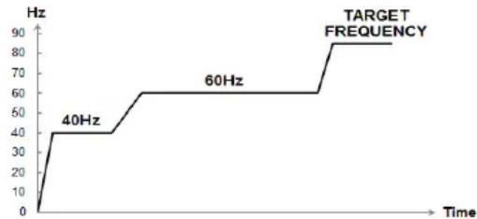
line
| Time | Frequency (Hz) | | ---- | -------------- | | 0 | 0 | | 40 | 40 | | 60 | 60 | | >60 | 80 |3.3.3 Startup Control for Heating and Domestic Hot Water Operation
Table 3-3.1: Component control during startup in heating and domestic hot water modes
| Component Control function and state | |
| Inverter compressor | Compressor startup program by figure3-3.1 |
| DC fan motor | Start the fan 10 seconds before the compressor starts, and then run half of the maximum speed, and then run at maximum speed 60s after the compressor startup |
| Electronic expansion valve | Position (steps) from 0 (fully closed) to 480 (fully open), controlled according to outdoor ambient temperature and in-water temperature |
| 4-way valve ON |
3.3.4 Startup Control for Cooling Operation
Table 3-3.2: Component control during startup in cooling mode
| Component Control function and state | |
| Inverter compressor | Compressor startup program by figure3-3.1 |
| DC fan motor | Start the fan 10 seconds before the compressor starts, and then run half of the maximum speed, and then run at maximum speed 60s after the compressor startup |
| Electronic expansion valve | Position (steps) from 0 (fully closed) to 480 (fully open), controlled according to outdoor ambient temperature and in-water temperature |
| 4-way valve OFF |
3.4 Normal Operation Control
3.4.1 Component Control during Normal Operation
Table 3-4.1: Component control during heating and domestic hot water operations
| Component Control function and state | |
| Inverter compressor | Controlled according to load requirement from hydraulic module |
| DC fan motor | Controlled according to outdoor ambient temperature and outdoor heat exchanger pipe temperature |
| Electronic expansion valve | Position (steps) from 0 (fully closed) to 480 (fully open), controlled according to in-water temperature, out-water temperature and discharge temperature |
| 4-way valve ON | |
Table 3-4.2: Component control during cooling operation
| Component Control function and state | |
| Inverter compressor | Controlled according to load requirement from hydraulic module |
| DC fan motor | Controlled according to outdoor ambient temperature and outdoor heat exchanger pipe temperature |
| Electronic expansion valve | Position (steps) from 0 (fully closed) to 480 (fully open), controlled according to in-water temperature, out-water temperature and discharge temperature |
| Four-way valve | OFF |
3.4.2 Compressor Output Control
The compressor rotation speed is controlled according to the load requirement. The compressor follows a fixed starting procedure as shown in figure 3-3.1. After finishing the startup, the compressor runs at the target rotation speed.
During normal operation the compressor speed is controlled according to inlet water temperature, target water temperature set by the user interface, the rate of change in inlet water temperature.
3.4.3 Compressor Step Control
The running speed of six-pole compressors (used on all models) in rotations per second (rps) is one third of the frequency (in Hz) of the electrical input to the compressor motor. The frequency of the electrical input to the compressor motors can be altered at a rate of 1Hz per second.
3.4.4 Four way Valve Control
The four-way valve is used to change the direction of refrigerant flow through the water side heat exchanger in order to switch between cooling and heating/DHW operations.
During heating and DHW operations, the four-way valve is on; during cooling and defrosting operations, the four-way valve is off.
3.4.5 DC Fan Control
Start the fan before the compressor starts, and fan runs at the initial speed. After the compressor runs a few minutes, the fan runs at a higher set speed.
3.4.6 Electronic Expansion Valve Control
The position of the electronic expansion valve (EEV) is controlled in steps from 0 (fully closed) to 480 (fully open).
At power-on
EEV first closes fully, and then moves to the standby position. After a few seconds EEV moves to an initial running position, which is determined according to operating mode, inlet water temperature and outdoor ambient temperature. A few minutes further, EEV is controlled according to inlet water temperature, outlet water temperature, discharge temperature and compressor speed.
■ When the unit is on standby
EEV keeps current position and delay a few seconds and opens fully.
■ When the unit stops
EEV keeps current position first and delay a few seconds and opens fully.
3.5 Protection Control
3.5.1 Low Pressure Protection Control
Figure 3-5.1: Low pressure protection control
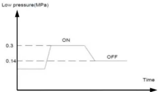
line
| Time | Low pressure(MPa) | | ---- | ----------------- | | Start | 0.14 | | ON | 0.3 | | Off | 0.14 |When the suction pressure drops below 0.14MPa the system displays P03 protection and the unit stops running. When the suction pressure rises above 0.3MPa, the compressor enters re-start control.
3.5.2 High Pressure Protection Control
This control protects the compress from the over-high refrigerant system pressure.
Figure 3-5.2: High pressure protection control
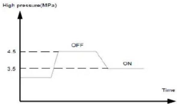
line
| Time | High pressure(MPa) | | :--- | :--- | | OFF | 4.5 | | ON | 3.5 |When the discharge pressure rises above 4.5MPa the system displays P02 protection and the unit stops running. When the discharge pressure drops below 3.5MPa, the compressor enters re-start control.
3.5.3 Discharge Temperature Protection Control
This control protects the compressor from abnormally high temperature.
Figure 3-5.3: High discharge temperature protection control
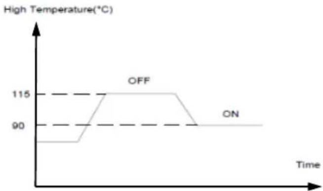
line
| Time | High Temperature(°C) | | ---- | -------------------- | | 0 | 90 | | 115 | 115 | | 200 | 90 |When the discharge temperature rises above 115^ C the system displays P05 protection and the unit stops running. When the discharge temperature drops below 95^ C, the compressor enters a re-start control.
3.5.4 Compressor Current Protection Control
This control protects the compressor from abnormally high currents. When the compressor current rises above maximum current the system displays E23 protection and the unit stops running. When the compressor current drops below maximum current, the compressor enters re-start control.
Table 3-5.1: Compressor current protection control
| model | 8-10kw | 12kw 1ph | 14-16kw 1ph |
| Maximum current (A) | 14 18 25 |
3.5.5 DC Fan Motor Protection Control
Check the feedback signal one minute after the fan starts. If the motor speed is lower than the default minimum speed or there is no feedback for one minute, the motor fault P11 will be displayed. If it occurred 10 times within 2 hours, the unit will shut down and be locked.
3.5.6 Water Side Heat Exchanger Anti-freeze Control
This control protects the water side heat exchanger from ice formation. The water side heat exchanger electric heater is controlled according to outdoor ambient temperature, inlet water temperature and outlet water temperature.
■ When all the conditions below are met, the unit will turn on the water side heat exchanger electric heater:
● the current operation mode of the unit is shutdown or standby;
● outdoor ambient temperature is below 4^ C;
- inlet water temperature or outlet water temperature(the minor one) is below 4°C;
■ When any one of the conditions below is met, the unit will turn off the water side heat exchanger electric heater:
● the current operation of the unit is neither shutdown nor standby;
● outdoor ambient temperature is above 6^ C;
- inlet water temperature or outlet water temperature(the minor one) is above 6°C;
3.5.7 Module Temperature Protection Control
This control protects the module from abnormally high temperatures. When the module temperature rises at or above the up limit value 96^ C, the interface displays E29 protection code and the unit stops running.
3.6 Special Control
3.6.1 Oil Return Operation
In order to prevent the compressor from running out of oil, the oil return operation is conducted to recover oil that has flowed out of the compressor and into the refrigerant piping.
When the compressor cumulative operating time with running rotation speed less than 50Hz has been reached 3 hours, the unit will start an oil-return operation.
The oil return operation ceases when any one of the following three conditions occurs:
■ Oil return operation duration has been reached 4 minutes.
■ The unit will turn off because of the protection.
■ "TURN OFF" command is received.
Table 3-6.1 Component control during oil-return operation
| Component Control functions and states | |
| Compressor | Runs at oil return operation rotation speed |
| Electronic expansion valve | Fully open |
| DC fan motor | Controlled according to outdoor heat exchanger pipe temperature |
| 4-way valve OFF |
3.6.2 Defrosting Operation
In order to recover heating capacity, the defrosting operation is conducted when the air side heat exchanger of the unit is performing as a condenser. The defrosting operation is controlled according to outdoor ambient temperature, air side heat exchanger refrigerant outlet temperature and the compressor running time.
Table 3-6.2: Component control during defrosting operation
| Component | Control functions and states |
| Compressor | Runs at defrosting operation rotation speed |
| Electronic expansion valve | Fully open |
| DC fan motor OFF | |
| 4-way valve OFF |
3.7 Role of Temperature Sensors in Control Functions
Figure 3-7.1: Location of the temperature sensors of all models 8-16kw
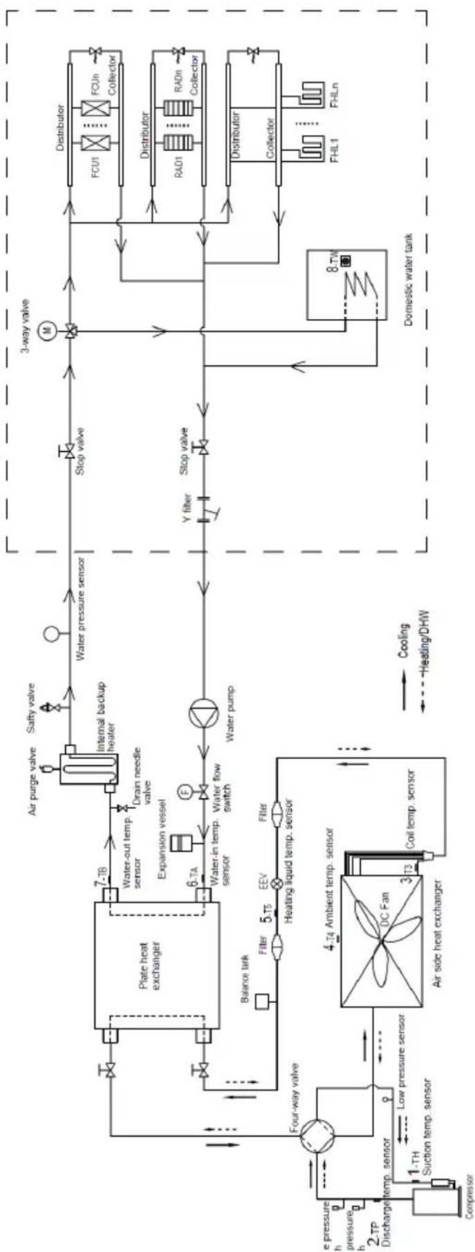
flowchart
graph TD
    A["Compressor"] --> B["4.T4 Ambient temp. sensor"]
    B --> C["Air side heat exchanger"]
    C --> D["DC Fan"]
    D --> E["Coil temp. sensor"]
    E --> F["Heating liquid temp. sensor"]
    F --> G["Balance tank"]
    G --> H["Plate heat exchanger"]
    H --> I["7-TB"]
    I --> J["Water-out temp. sensor"]
    J --> K["Drain needle valve"]
    K --> L["Internal backup heater"]
    L --> M["Salty valve"]
    M --> N["Water pressure sensor"]
    N --> O["Stop valve"]
    O --> P["3-way valve"]
    P --> Q["Distributor"]
    Q --> R["FCU1"]
    Q --> S["FCUn Collector"]
    P --> T["Distributor"]
    T --> U["RAD1"]
    T --> V["RADn Collector"]
    P --> W["Distributor"]
    W --> X["Collector"]
    P --> Y["Domestic water tank"]
    Y --> Z["FHL1"]
    Y --> AA["FHLn"]
    B --> AB["Low pressure sensor"]
    AB --> AC["4.T4 Ambient temp. sensor"]
    AC --> AD["DC Fan"]
    AD --> AE["Coil temp. sensor"]
    AE --> AF["Heating liquid temp. sensor"]
    AF --> AG["Balance tank"]
    AG --> AH["4.T4 Ambient temp. sensor"]
    AH --> AI["DC Fan"]
    AI --> AJ["Coil temp. sensor"]
    AJ --> AK["Heating liquid temp. sensor"]
    AK --> AL["Balance tank"]
    AL --> AM["4.T4 Ambient temp. sensor"]
    AM --> AN["DC Fan"]
    AN --> AO["Coil temp. sensor"]
    AO --> AP["Heating liquid temp. sensor"]
    AP --> AQ["Balance tank"]
    AQ --> AR["4.T4 Ambient temp. sensor"]
    AR --> AS["DC Fan"]
    AS --> AT["Coil temp. sensor"]
    AT --> AU["Heating liquid temp. sensor"]
    AU --> AV["Balance tank"]
Table 3-7.1: All the temperature sensors
| Item | Name | Label | Mode | Control functions |
| 1 Suction | temp. sensor TH | Cooling Electronic expansion valve control | ||
| Heating Electronic expansion valve control | ||||
| 2 Discharge | temp. sensor TP | Cooling | Electronic expansion valve control | |
| Discharge temp. protection control | ||||
| Heating | Electronic expansion valve control | |||
| Discharge temp. protection control | ||||
| 3 Coil temp. sensor T3 | Cooling | Electronic expansion valve control | ||
| DC fan control | ||||
| Compressor output control | ||||
| Heating | Electronic expansion valve control | |||
| DC fan control | ||||
| Defrosting operation control | ||||
| 4 | Outdoor ambient temp. sensor | T4 | Cooling | Compressor startup control |
| Compressor output control | ||||
| Electronic expansion valve control | ||||
| DC fan control | ||||
| Crankcase heater control | ||||
| Heating | Compressor startup control | |||
| Compressor output control | ||||
| Electronic expansion valve control | ||||
| DC fan control | ||||
| Defrosting operation control | ||||
| Crankcase heater control | ||||
| 5 | Liquid refrigerant temp. sensor | T5 | Cooling | Anti-freezing protection control |
| Heating / | ||||
| 6 Inlet water | water temp. sensor TA | Cooling | Anti-freezing protection control | |
| Compressor on/off and output control | ||||
| Oil-returning control | ||||
| Electronic expansion valve control | ||||
| Heating | Compressor on/off and output control | |||
| Oil-returning control | ||||
| Defrosting operation control | ||||
| Electronic expansion valve control | ||||
| 7 | Outlet water temp. sensor | TB | Cooling | Anti-freezing protection control |
| Electronic expansion valve control | ||||
| Heating | Compressor output control | |||
| Defrosting operation control | ||||
| Electronic expansion valve control | ||||
| 8 | Domestic water tank temp. sensor | TW | DHW | Compressor output/Backup electric heater control |
3.8 EEPROM Parameter Setting
Press "M" and "Up" two keys at the same time, and then enter the password "1212" to adjust EEPROM parameter value. Refer to the table below for the detailed setting.
| Item | Name | Code | Default | Unit | Range | Accuracy |
| 1 | Air conditioning water temperature return difference | Ta 2 °C | 1~5 1 | |||
| 2 | Hot water temperature difference | Tb | 5 | °C | 2~15 | 1 |
| 3 | Cooling target exhaust temperature correction | TargetTPc | 0 | °C | -10~15 | 1 |
| 4 | Heating superheat | SHh | -1 | °C | -5~10 | 1 |
| 5 | Compressor frequency in refrigeration test mode | LCF_C | 68 | Hz | 20~120 | 1 |
| 6 | Compressor frequency in heating test mode | LCF_H | 68 | Hz | 20~120 | 1 |
| 7 | Compressor frequency in hot water test mode | LCF_W | 68 | Hz | 20~120 | 1 |
| 8 | Cooling test mode EEV opening | EEV_C | 250/5 | P | (0~480)/5 | 1 |
| 9 | Heating test mode EEV-1 opening | EEV_H | 150/5 | P | (0~480)/5 | 1 |
| 10 | Hot water test mode EEV-1 opening | EEV_W | 150/5 | P | (0~480)/5 | 1 |
| 11 | Defrost entry temperature | DST | -5 | °C | -15~0 | 1 |
| 12 | Defrost enters temperature difference | Dt | 12 | °C | 0~15 | 1 |
| 13 | Judgment time of first defrost | T1 | 40 | min | 20~90 | 1 |
| 14 | Defrosting process EEV opening | Opl | 480/5 | P | (0~480)/5 | 1 |
| 15 | Defrost compressor frequency | FD | 12 | Hz | 30~120 | 1 |
| 16 | Maximum operating frequency | Fmax | 85 | Hz | 30~120 | 1 |
| 17 | Power-off memory | PR | 1 | 0/1 | 0-disable 1-enable | / |
| 18 | Silent mode frequency limit | Fs | 55 | Hz | 30~120 | 1 |
| 19 | Sterilization set temperature | Tx | 65 | °C | 55~75 | 1 |
| 20 | Disinfection duration time | Td | 30 | Min | 20~120 | 1 |
| 21 | Run mode priority | Mp | 0 | 0/1/2 | 0-DHW 1-Space AC 2-Preempt | / |
| 22 | Compressor resonance point 1 | FR1 | 0 | Hz | 0~120 | 1 |
| 23 | Compressor resonance point 2 | FR2 | 0 | Hz | 0~120 | 1 |
| 24 | Compressor resonance point 3 | FR3 | 0 | Hz | 0~120 | 1 |
| 25 | Compressor resonance point 4 | FR4 | 0 | Hz | 0~120 | 1 |
| 26 | Ambient temperature for electric heating of water tank | Teh | 4 | °C | -10~40 | 1 |
| 27 | Whether automatic temperature adjustment is effective | Auto heating Adjust enable | 0 0/1 | 0-disable 1-enable | 1 | |
| 28 | Temperature compensation high point | Hi_A | 5 | °C | 0~20 | 1 |
| 29 | Temperature compensation low point | Lo_A | 0 | °C | -20~0 | 1 |
| 30 | Maximum temperature compensation | A | 5 | °C | 0~10 | 1 |
| 31 | Whether the high heating temperature shutdown is effective | To enable high temp. heating shutdown | 0 0/1 | 0-disable 1-enable | 1 | |
| 32 | Heating high temperature shutdown temperature setting | T4h | 24 | °C | 10~30 | 1 |
| 33 | PWM water pump brand | MPumpTyp | 3 | / | 0-AC pump 1-OMT1 2-Grundfos 3-Wilo 4-OMT2 | 1 |
| 34 | Pump running status in heating standby mode | H-Pump | 3 0/1 | 0-On 1min OFF 3min 1-ON 1min OFF 10min 2-On 2min OFF 15min 3-Always On | 1 | |
| 35 | Low temperature stop compressor temperature setting | T4L | -30 | °C | -40~-21 | 1 |
| 36 | Pipeline electric heating is effective or invalid | HD | 0 0/1 | 0-enable 1-disable | 1 | |
| 37 | Whether the cooling mode is effective | Cool on enable | 0 0/1 | 0-enable 1-disable | 1 | |
| 38 | Whether the high pressure 2 switch is effective (system parameter) | Middle pressure Switch enable | 0 0/1 | 0-enable 1-disable | 1 | |
| 39 | Minimum opening setting | MinEEV | 80/5 | P | (0~480)/5 | 1 |
| 40 | Minimum water temperature requirement when entering defrost | Tdf | 10 | °C | 0~40 | 1 |
| 41 | Ambient temperature of pipeline electric heating | T4g | -20 | °C | -40~20 | 1 |
| 42 | Defrost exit temperature | Ft | 15 | °C | 10~25 | 1 |
| 43 | Maximum defrost operating time | FT | 10 | Min | 1~20 | 1 |
| 44 | Return oil into the lowest frequency | Fo | 50 | Hz | 30~60 | 1 |
| 45 | Test mode AC fan speed | TF | 2 | / | 1-low speed 2-high speed | / |
| 46 | Chassis electric heating start temperature | BHon | -5 | °C | -15~0 | 1 |
| 47 | Minimum operating frequency | Fmin | 25 | Hz | 20~100 | 1 |
| 48 | Heating mode switch | HeatChange | 0 | / | 0/1 | / |
| 49 | Correction of heating target exhaust temperature | TargetTPh | 0 | °C | -10~15 | 1 |
| 50 | EEPROM Reset | / | 0 | / | 0-Normal 1-Reset | 1 |
| 51 | Standby water pump speed | SB-PWMout | 35 | % | 10~100 | 1 |
| 52 | Test mode DC fan speed | FspeedT | 900/15 | rpm | 200~1000/15 | 1 |
| 53 | Minimum DC fan speed | FanMin | 250/15 | rpm | 200~500/15 | 1 |
| 54 | Minimum DC fan speed | FanMax | 825/15 | rpm | 500~1000/15 | 1 |
| 55 | Maximum DC fan speed | NoiseFan | 650/15 | rpm | 300~1000/15 | 1 |
| 56 | Cool coil pipe temp. | CondT | 40 | °C | 20~60 | 1 |
| 57 | Heat coil pipe temp. | EvapT | 5 | °C | -10~20 | 1 |
| 58 | DC fan resonance point 1 | SR1 | 0/15 | rpm | 0~1000/15 | 1 |
| 59 | DC fan resonance point 2 | SR2 | 0/15 | rpm | 0~1000/15 | 1 |
| 60 | DC fan resonance point 3 | SR3 | 0/15 | rpm | 0~1000/15 | 1 |
| 61 | Test mode PWM pump speed | Test_P | 100 | % | 50~100 | 1 |
| 62 | PWM pump minimum speed | Min-PWMout | 70 | % | 50~100 | 1 |
| 63 | Trv is effective or not | enTrV | 1 | 0/1 | 0-disable1-enable | 1 |
| 64 | Four way switching fault judgment temperature difference | Trv | 3 | °C | 0~10 | 1 |
| 65 | EVI heat or DHW superheat | SHe | 6 | °C | -5~25 | 1 |
| 66 | Cool test mode EEV-2 open | EEV_C | 0/5 | P | (0~480)/5 | 1 |
| 67 | Heat test mode EEV-2 open | EEV_H | 150/5 | P | (0~480)/5 | 1 |
| 68 | DHW test mode EEV-2 open | EEV_W | 150/5 | P | (0~480)/5 | 1 |
| 69 | Commercial mode heating frequency | FreqTestH | 60 | Hz | 20~100 | 1 |
| 70 | Commercial mode heating EEV-1 open | EEVTestH-1 | 250/5 | P | (0~480)/5 | 1 |
| 71 | Commercial mode heating EEV-2 open | EEVTestH-2 | 150/5 | P | (0~480)/5 | 1 |
| 72 | Commercial mode cooling frequency | FreqTestC | 40 | Hz | 20~100 | 1 |
| 73 | Commercial modecooling EEV-1 open | EEVTestC-1 | 300/5 | P | (0~480)/5 | 1 |
| 74 | Commercial mode cooling EEV-2 open | EEVTestC-2 | 0 | P | (0~480)/5 | 1 |
| 75 | Chassis heater on time | BaseHeatTime | 6 | 10Min | 0~100 | 1 |
| 76 | Group control address | IP | 0 | 0-15 | 1 | |
| 77 | Low pressure check type | LPS | 1 | / | 0-low pressure switch1- low pressure sensor | 1 |
| 78 | Pump running status in cooling standby mode | C-Pump | 3 | 0/1 | 0-on 1min off3min1-on 1min off10min2-on 2min off15min3-Always on | 1 |
| 79 | Chassis heater enable or disable | TH4 1 0/1 | 0-disable1-enable | 1 | ||
| 80 | EVI-main cool superheat(≤60Hz) | SHc1 | 4 | °C | 0~15 | 1 |
| 81 | EVI-sub cool superheat (≤60Hz) | SCe1 | 6 | °C | 0~15 | 1 |
| 82 | EVI-main cool superheat (≥70Hz) | SHc2 | 5 | °C | 0~15 | 1 |
| 83 | EVI-sub cool superheat (≥70Hz) | SCe2 | 6 | °C | 0~15 | 1 |
| 84 | Heating superheat | SHlps | 4 | °C | 0~15 | 1 |
| 85 | EVI startup frequency | F-EVI | 60 | Hz | 30~100 | 1 |
| 86 | Heat four way valve on delay | 4 Way-on time | 10 | S | 1-100 | 1 |
| 87 | Heat four way valve off delay | 4 Way-Off time | 120 | S | 0-120 | 1 |
| 88 | Target water temperature type | In/Out_Change | 0 | / | 0-TA Inlet water1-TB Outlet water | 1 |
| 89 | Outlet water control differential coefficient | a | 3 | °C | 1-10 | 1 |
| 90 | Second compressor startup frequency | F-Start2 | 60 | Hz | 40-90 | 1 |
| 91 | Heat pump off frequency | F-Stop | 25 | Hz | 20-90 | 1 |
| 92 | Defrost 4-way valve switch frequency | FD-Change | 38 | Hz | 20-90 | 1 |
| 93 | Compressor off delay | COMP-Off time | 0 | S | 0-60 | 1 |
| 94 | EEV off delay | EEV- Stop time | 60 | S | 0-120 | 1 |
| 95 | Test mode type | Test_Typ | 0 | / | 0-normal1-standard2-ERP13-ERP2 | 1 |
| 96 | T3 change rate when defrost | DeT | 40/10 | °C | (10-100)/10 | 1 |
| 97 | T4 switch in TP protection | TP-Change | -15 | °C | 0~ -30 1 | |
| 98 | Water pressure check enable | WPS | 0 | 0/1 | 0-disable1-enable | 1 |
| 99 | Compressor resonance point 5 | FR5 | 0 | Hz | 0~120 | 1 |
3.9 Electric Wiring Diagram
3.9.1 (GHP-MM08); (GHP-MM10); (GHP-MM12)
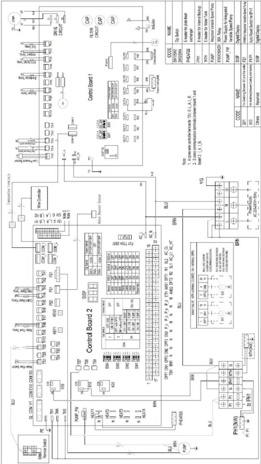
text_image
BRN Remote Switch PE TH1 THA TH3 K18 PUMP_PW HEAT1 N HEAT2 N HEAT3 N HEAT4 BRN PHEAFEB BLU IPH1(3kW) P1 P1 to IPH1 BLU Control Board 2 DISP Dig Switch Factory Default SW4= 1/2/34 OFF/OFF/OFF/OFF SAG= 1 OFF SAG= 1/2/34 OFF/OFF/OFF/OFF FUT T10A 25V AC_L 17 16 32 OFF1 ON1 OFF2 ON2 OFF3 ON4 P_c P_o P_s P_d ETH AHS1 DFT1 R1 SL2 AC_CL TBH BH1 N N N N N N N N AHS2 DFT2 R2 SL1 AC_L1 AC_HT BLU BRN SWAY VALUE: OFF+/NORMAL CLOSED, ON+/NORMAL OPEN 1 OFF 2 ON1 3 ON2 4 ON3 5 ON4 6 ON5 7 ON6 8 ON7 9 ON8 10 ON9 11 ON10 12 ON11 ON12 ON13 ON14 ON15 ON16 ON17 ON18 ON19 ON20 ON21 ON22 ON23 ON24 ON25 ON26 ON27 ON28 ON29 ON30 ON31 ON32 ON33 ON34 ON35 ON36 ON37 ON38 ON39 ON40 ON41 ON42 ON43 ON44 ON45 ON46 ON47 ON48 ON49 ON50 ON51 ON52 ON53 ON54 ON55 ON56 ON57 ON58 ON59 ON60 ON61 ON62 ON63 ON64 ON65 ON66 ON67 ON68 ON69 ON70 ON71 ON72 ON73 ON74 ON75 ON76 ON77 ON78 ON79 ON80 MW LOTO OUTPUT: GUANGUARD-SURVIC GUACOMINIUS-ENIXAVIC. SV1 SWITCHING DETRATES: AC AND HOT WATER, SV2 SWITCHING DETRATES: CCOL-BACKED HEATRIC. BRN POWER SUPPLY: AC 220-240V~50Hz SPINION TERMINALS COM C COM I COM T COM L Wire Controller Low Pressure Sensor LPS AC Power Sensor AC Power Sensor TS5 TS4 TS3 TS2 TS1 TSH TSH TSH TSH TSH TSH TSH TSH TSH TSH TSH TSH TSH TSH TSH TSH TSH TSH TSH TSH TSH TSH TSH TSH TSH TSH TSH TSH TSH TSH TSH TSH TSH TSH TSH TSH TSH TSH TSH TSH TSH TSH TSH TSH TSH TSH TSH TSH TSH TSH TSH DRIVE CIRCUIT CAP CAP CAP OUT 10 SW1 SW2 UP Switch Control Signal OUT 1/2/34 ORCHORON OFF OUT 1/2/34 ORCHORON OFF FAN1 OUT 1 OUT 2 OUT 3 OUT 4 OUT 5 OUT 6 OUT 7 OUT 8 OUT 9 OUT 10 OUT 11 OUT 12 OUT 13 OUT 14 OUT 15 OUT 16 OUT 17 OUT 18 OUT 19 OUT 20 OUT 21 OUT 22 OUT 23 OUT 24 OUT 25 OUT 26 OUT 27 OUT 28 OUT 29 OUT 30 OUT 31 OUT 32 OUT 33 OUT 34 OUT 35 OUT 36 OUT 37 OUT 38 OUT 39 OUT 40 OUT 41 OUT 42 OUT 43 OUT 44 OUT 45 OUT 46 OUT 47 OUT 48 OUT 49 OUT 50 OUT 51 OUT 52 OUT 53 OUT 54 OUT 55 OUT 56 OUT 57 OUT 58 OUT 59 OUT 60 OUT 61 OUT 62 OUT 63 OUT 64 OUT 65 OUT 66 OUT 67 OUT 68 OUT 69 OUT 70 OUT 71 OUT 72 OUT 73 OUT 74 OUT 75 OUT 76 OUT 77 OUT 78 OUT 79 OUT 80 OUT 81 OUT 82 OUT 83 OUT 84 OUT 85 OUT 86 OUT 87 OUT 88 OUT 89 OUT 90 OUT 91 OUT 92 OUT 93 OUT 94 OUT 95 OUT 96 OUT 97 OUT 98 OUT 99 OUT CODE NAME DISP Digital Display SV1 For Switching Between AC and Hot water FS1 PINM for Integrated Variable Speed Pump SV2 For Switching Between Coding and Heating P1 P1 Auto Reset Switch for IPH1 Others Reserved DISP Digital Display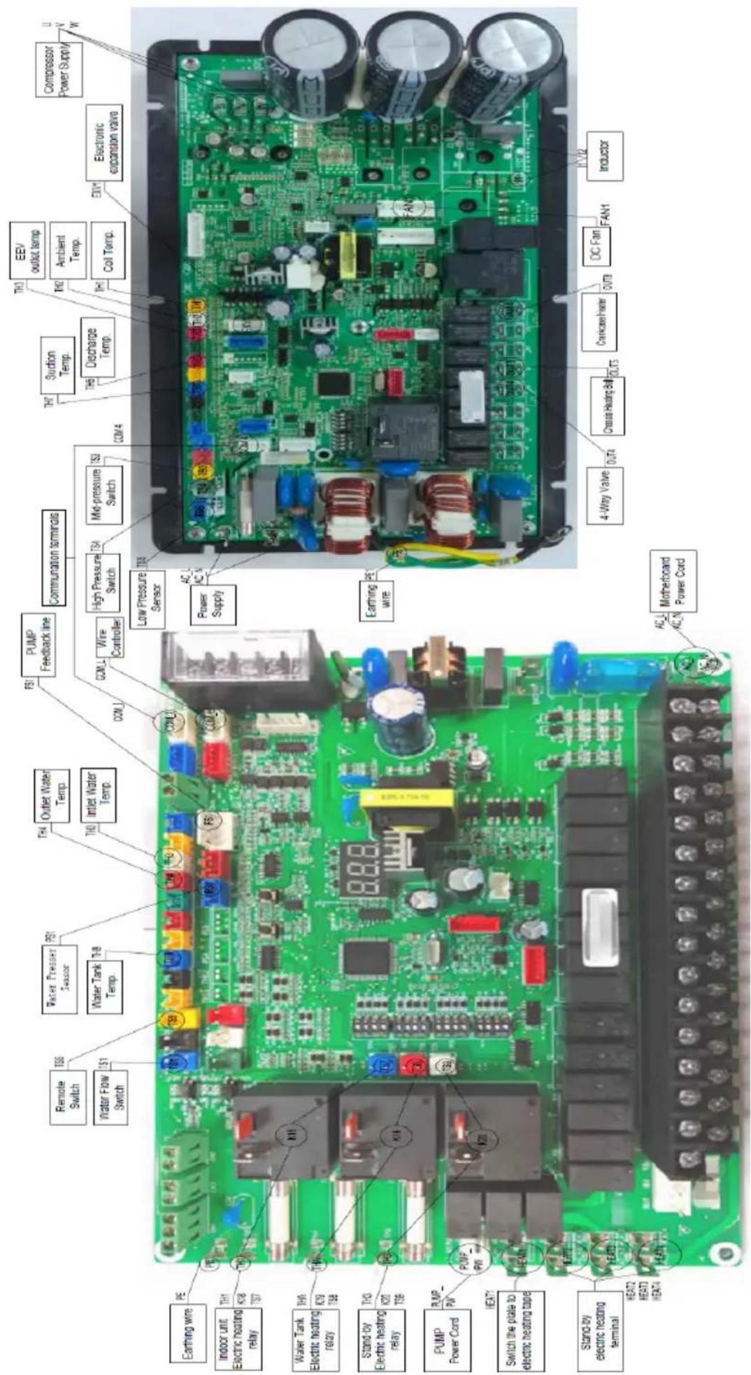
text_image
Remote Switch Water Flow Switch Water Pressur Sensor Water Tank Temp TS1 TS2 TS3 TS4 TS5 TS6 TS7 TS8 TS9 TS10 TS11 TS12 TS13 TS14 TS15 TS16 TS17 TS18 TS19 TS20 TS21 TS22 TS23 TS24 TS25 TS26 TS27 TS28 TS29 TS30 TS31 TS32 TS33 TS34 TS35 TS36 TS37 TS38 TS39 TS40 TS41 TS42 TS43 TS44 TS45 TS46 TS47 TS48 TS49 TS50 TS51 TS52 TS53 TS54 TS55 TS56 TS57 TS58 TS59 TS60 TS61 TS62 TS63 TS64 TS65 TS66 TS67 TS68 TS69 TS70 TS71 TS72 TS73 TS74 TS75 TS76 TS77 TS78 TS79 TS80 TS81 TS82 TS83 TS84 TS85 TS86 TS87 TS88 TS89 TS90 TS91 TS92 TS93 TS94 TS95 TS96 TS97 TS98 TS99 TS1003.9.2 (GHP-MM14) ; (GHP-MM16)
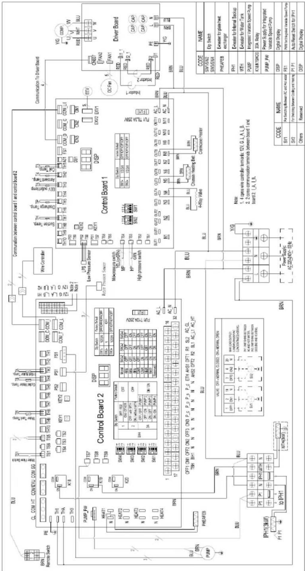
text_image
BRIN Remote Switch PE TH1 THA TH3 K18 ON COB TS4 TS3 TS2 KEY1 KEY2 PS2 PS1 FS1 COM_C COM_I COM_T COM_L Control Board 2 DISP Dip Switch Factory Set/Well OFF: 100kN OFF/OFF/OFF/OFF SWG: 1 OFF SWG> 100kN OFF/OFF/OFF/OFF LPS Low Pressure Sensor Water Pressure Sensor Mid-pressure switch YEL(on/GRN) MP HP GRN High pressure switch Control Board 1 Dip Switch Factory Set/Well SWI: 1/2/34 OFF/OFF/OFF/OFF SWG: 1/2/34 OFF/OFF/OFF/OFF DIP Switch Factory Set/Well SWI: 1/2/34 OFF/OFF/OFF/OFF WTP: 1/2/34 OFF/OFF/OFF/OFF SRS: 1/2/34 OFF/OFF/OFF/OFF SRS: 1/2/34 OFF/OFF/OFF/OFF DC Fan Driver Board CNB7 FAN2 FAN1 RED 11.1 RED 12.1 RED 1 PE L N BLU BLU BRIN PHEAFEB BLU IPH1(3kW) P1 P1 to IPH1 BRIN Control Board 2 DISP Dip Switch Factory Set/Well OFF: 100kN OFF/OFF/OFF/OFF SWG: 1 OFF ON ON ON ON ON ON ON ON ON ON ON ON ON ON ON ON ON ON ON ON ON ON ON ON ON ON ON ON ON ON ON ON ON ON ON ON ON ON ON ON ON ON ON ON ON ON ON ON ON ON ON ON ON ON ON ON ON ON ON ON ON ON ON ON ON ON ON ON ON ON ON ON ON ON ON ON ON ON ON ON ON ON ON ON ON ON ON ON ON ON ON ON ON ON ON ON ON ON ON ON On On On On On On On On On On On On On On On On On On On On On On On On On On On On On On On On On On On On On On On On On On On On On On On On On On On On On On On On On On On On On On On On On On On On On On On On On On On On On On On On On On On On On On On On On On On On On On On On On On On On Off: 16 AC_L AC_N AC_2 AC_L AC_L AC_L AC_L AC_L AC_L AC_L AC_L AC_L AC_L AC_L AC_L AC_L AC_L AC_L AC_L AC_L AC_L AC_L AC_L AC_L AC_L AC_L AC_L AC_L AC_L AC_L AC_L AC_L AC_L AC_L AC_L AC_L AC_L AC_L AC_L AC_L AC_L AC_L AC_L AC_L AC_L AC_L AC_L AC_L AC_L AC_L AC_L AC_L AC_L AC L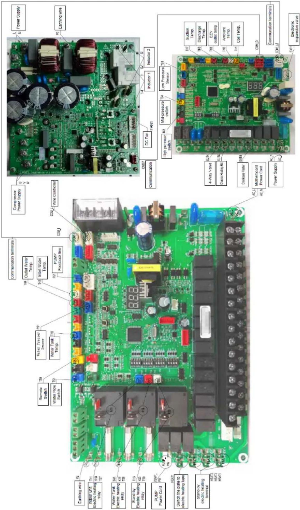
text_image
Communication terminals Compressor Power Supply U/V W Power Supply L N Water Flow Switch TS1 Water Flow Switch TS2 Water Tank Temp. TS3 Inset Water Temp. TS4 PUMP Feedback line COMJ Wire Controller PE Earthing wire Indoor unit Electric heating relay TH1 K18 TST TH2 TH3 TH3 K19 TSB TH3 K20 TSB PUMP Power Cord PUMP PW Switch the plate to electric heating tape HEAT1 HEAT2 HEAT3 HEAT4 Stand-by Electric heating terminal Heat1 HEAT2 HEAT3 HEAT4 Chassis Heating 5d Chassis Heater Motherboard Power Cord Power Supply AC-L AC-N 4-Way Valve OUT4 Circuit Audio 5d OUT6 Circuit Audio 5d OUT7 Circuit Audio 5d OUT8 Circuit Audio 5d OUT9 Circuit Audio 5d OUT10 Circuit Audio 5d OUT11 Circuit Audio 5d OUT12 Circuit Audio 5d OUT13 Circuit Audio 5d OUT14 Circuit Audio 5d OUT15 Circuit Audio 5d OUT16 Circuit Audio 5d OUT17 Circuit Audio 5d OUT18 Circuit Audio 5d OUT19 Circuit Audio 5d OUT20 Circuit Audio 5d OUT21 Circuit Audio 5d OUT22 Circuit Audio 5d OUT23 Circuit Audio 5d OUT24 Circuit Audio 5d OUT25 Circuit Audio 5d OUT26 Circuit Audio 5d OUT27 Circuit Audio 5d OUT28 Circuit Audio 5d OUT29 Circuit Audio 5d OUT30 Circuit Audio 5d OUT31 Circuit Audio 5d OUT32 Circuit Audio 5d OUT33 Circuit Audio 5d OUT34 Circuit Audio 5d OUT35 Circuit Audio 5d OUT36 Circuit Audio 5d OUT37 Circuit Audio 5d OUT38 Circuit Audio 5d OUT39 Circuit Audio 5d OUT40 Circuit Audio 5d OUT41 Circuit Audio 5d OUT42 Circuit Audio 5d OUT43 Circuit Audio 5d OUT44 Circuit Audio 5d OUT45 Circuit Audio 5d OUT46 Circuit Audio 5d OUT47 Circuit Audio 5d OUT48 Circuit Audio 5d OUT49 Circuit Audio 5d OUT50 Circuit Audio 5d OUT51 Circuit Audio 5d OUT52 Circuit Audio 5d OUT53 Circuit Audio 5d OUT54 Circuit Audio 5d OUT55 Circuit Audio 5d OUT56 Circuit Audio 5d OUT57 Circuit Audio 5d OUT58 Circuit Audio 5d OUT59 Circuit Audio 5d OUT60 Circuit Audio 5d OUT61 Circuit Audio 5d OUT62 Circuit Audio 5d OUT63 Circuit Audio 5d OUT64 Circuit Audio 5d OUT65 Circuit Audio 5d OUT66 Circuit Audio 5d OUT67 Circuit Audio 5d OUT68 Circuit Audio 5d OUT69 Circuit Audio 5d OUT70 Circuit Audio 5d OUT71 Circuit Audio 5d OUT72 Circuit Audio 5d OUT73 Circuit Audio 5d OUT74 Circuit Audio 5d OUT75 Circuit Audio 5d OUT76 Circuit Audio 5d OUT77 Circuit Audio 5d OUT78 Circuit Audio 5d OUT79 Circuit Audio 5d OUT80 Circuit Audio 5d OUT81 Circuit Audio 5d OUT82 Circuit Audio 5d OUT83 Circuit Audio 5d OUT84 Circuit Audio 5d OUT85 Circuit Audio 5d OUT86 Circuit Audio 5d OUT87 Circuit Audio 5d OUT88 Circuit Audio 5d OUT89 Circuit Audio 5d OUT90 Circuit Audio 5d OUT91 Circuit Audio 5d OUT92 Circuit Audio 5d OUT93 Circuit Audio 5d OUT94 Circuit Audio 5d OUT95 Circuit Audio 5d OUT96 Circuit Audio 5d OUT97 Circuit Audio 5d OUT98 Circuit Audio 5d OUT99 Circuit Audio 5d OUT100Part 4 Troubleshooting
4.1 Unit Electric Control Box Layout
Figure 4-1.1: (GHP-MM08)
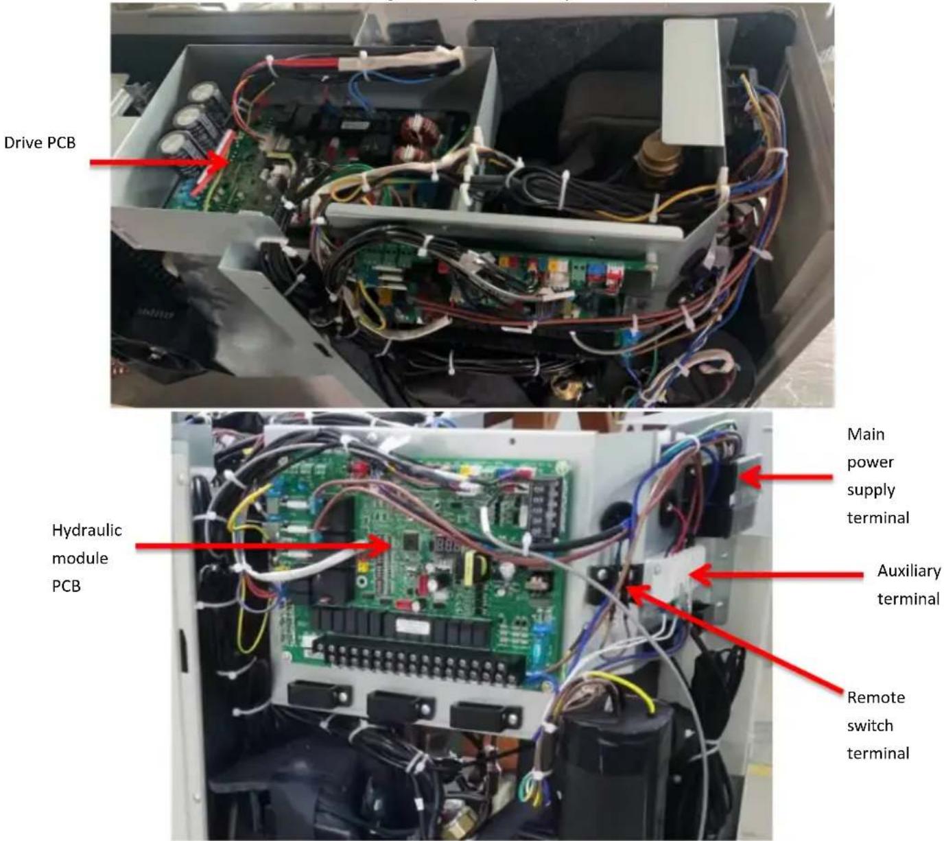
text_image
Drive PCB Hydraulic module PCB Main power supply terminal Auxiliary terminal Remote switch terminalFigure 4-1.2: (GHP-MM10)/(GHP-MM12)
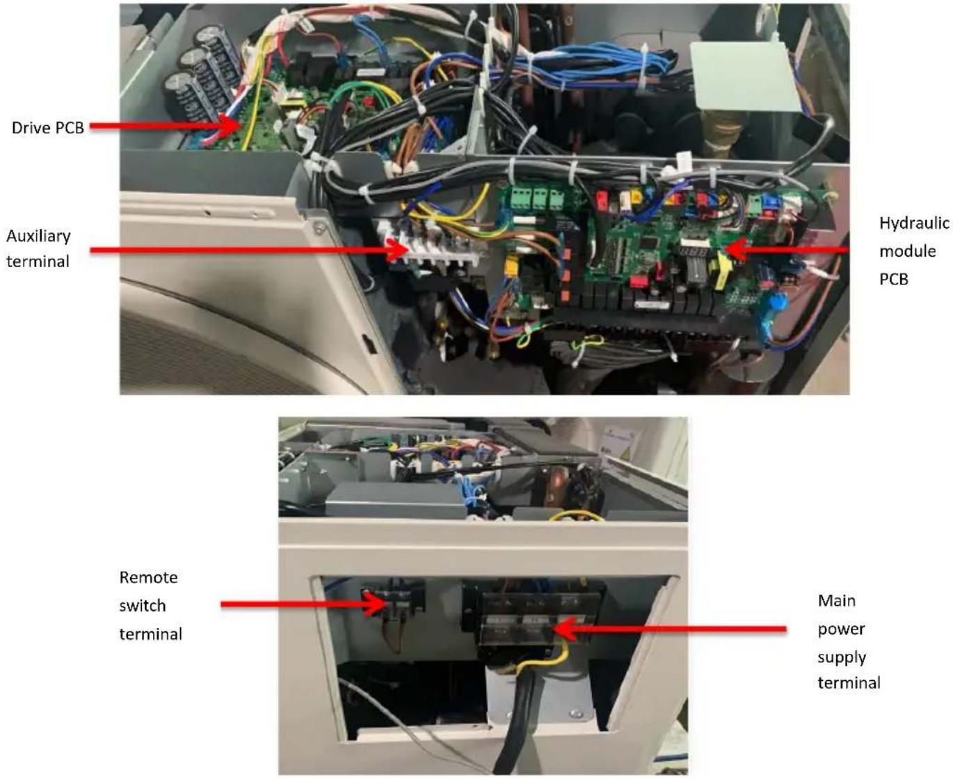
text_image
Drive PCB Auxiliary terminal Hydraulic module PCB Remote switch terminal Main power supply terminalFigure 4-1.3: (GHP-MM14)/(GHP-MM16)
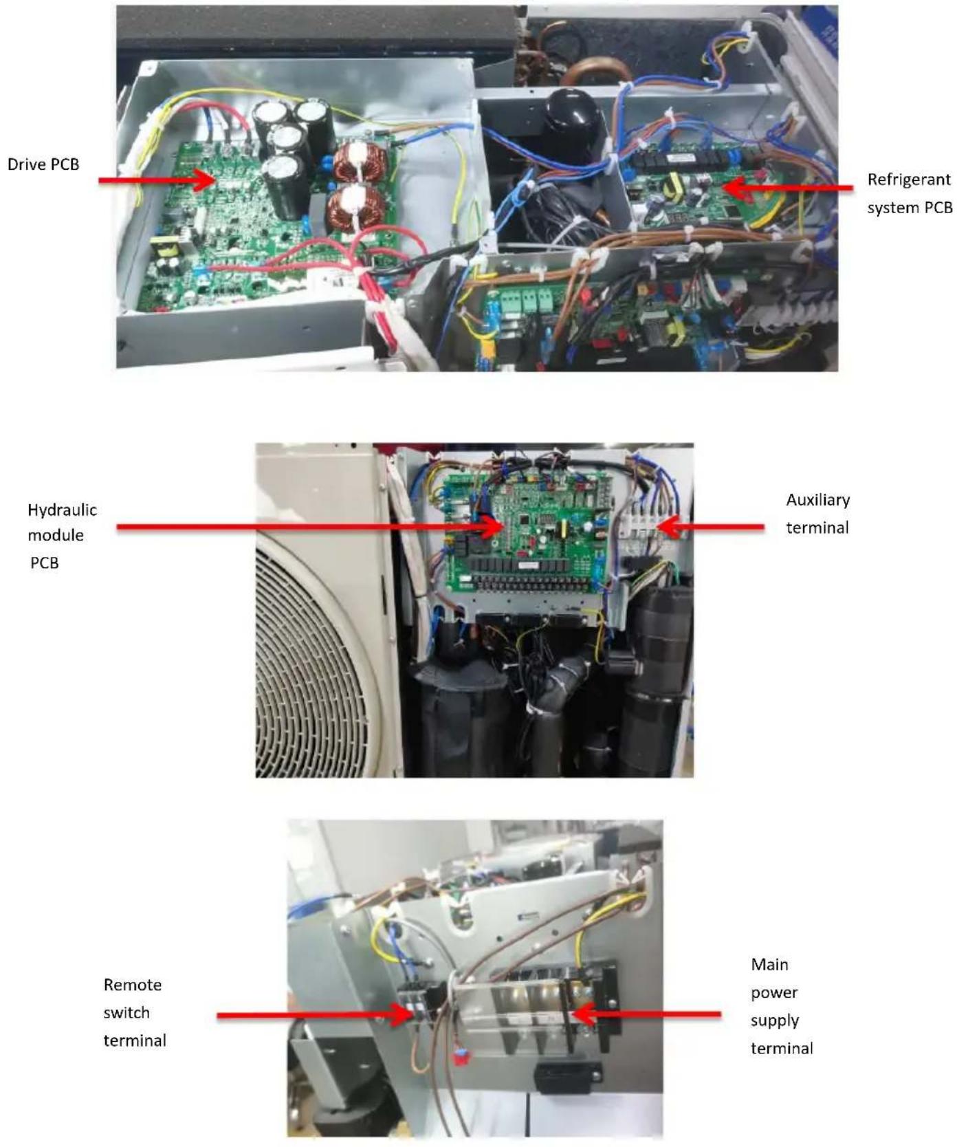
4.2 Unit PCBs
4.2.1 Types
Heat pump has two types of PCBs – one for the hydraulic system and the other for the refrigerant system. All models share the same hydraulic system PCB. The number of PCBs of each model is for reference to Table 4-2.1 below.
Table 4-2.1 PCB
| Model/Number | 8kw/10kw | 12kw | 14kw/16kw |
| Refrigerant system module | 1 1 | 1 | |
| Inverter module 1 | |||
| Hydraulic module PCB 1 1 1 | |||
| Total | 2 | 2 | 3 |
The locations of each PCB in the unit electric control boxes are shown in Figures 4-2.1, 4-2.2, 4-2.3, 4-2.4, 4-2.5. For 8/10/12kw, Inverter module and refrigerant system module constitute an integrated PCB which is called drive PCB. For 14/16kw, Drive PCB and refrigerant system PCB are separate.
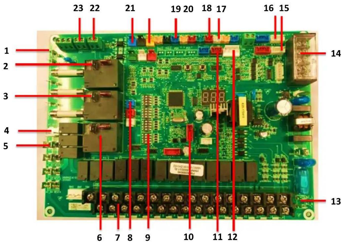
4.2.2 Hydraulic Module PCB
Figure 4-2.1: PCB for Hydraulic Module
text_image
23 22 21 19 20 18 17 16 15 1 2 3 4 5 14 13 6 7 8 9 10 11 12Table 4-2.2: Hydraulic module PCB
| Items Port label function | ||
| 1 | PE | Port for ground |
| 2 | K18 | Relay for internal backup heater(IBH,3Kw) |
| 3 | K19 | Relay for domestic water tank heater(3kW) |
| 4 | Pump | Power supply of internal pump |
| 5 | HEAT 1 | Plate heat exchange anti-freezing heater |
| 6 K20 Relay (Reserved,3kW) | ||
| 7 CON1 | Terminals(Reserved) | |
| 8 | TS7 | High temperature protection switch for IBH |
| 9 SW1/2 | /3/4 Dip switch | |
| 10 | FLS | Program update |
| 11 | PS1 | Water pressure sensor |
| 12 | FS1 | Internal pump speed feedback |
| 13 AC Power supply | ||
| 14 | U19 | Communication ports |
| 15 | COM_L | Wired controller |
| 16 | COM_I | Communication port |
| 17 | TH3 | Inlet water temperature |
| 18 | TH4 | Outlet water temperature |
| 19 | TH8 | Domestic water tank temperature |
| 20 | TS5 | Remote switch |
| 21 | TS1 | Water flow switch |
| 22 | SG | Reserved |
| 23 | EVU | Reserved |
4.2.3 Drive and refrigerant system PCB
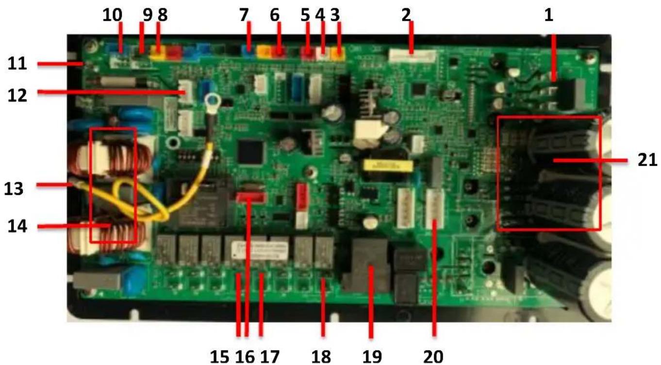
Figure 4-2.2: (GHP-MM08)
text_image
10 9 8 7 6 5 4 3 2 1 11 12 13 14 15 16 17 18 19 20 21Table 4-2.3: (GHP-MM08)
| Items Port label function | ||
| 1 U/V/W | Compressor output | |
| 2 JTAG Drive program update | ||
| 3 | TH1 | Coil temperature sensor |
| 4 | TH2 | Outdoor ambient temperature sensor |
| 5 | TH3 | Refrigerant liquid temperature sensor |
| 6 | TH5 | Discharge temperature sensor |
| 7 | TH7 | Suction temperature sensor |
| 8 | TS3 | HP2: Middle pressure switch |
| 9 | TS4 | HP1: High pressure switch |
| 10 | TS5 | LPS: low pressure sensor |
| 11 AC Power supply | ||
| 12 | COM4 | Communication with hydraulic module PCB |
| 13 | PE1 | Port for ground |
| 14 | / | Filter components |
| 15 | OUT4 | 4-way valve |
| 16 | FLS | PCB Program update |
| 17 OUT 5 Chassis heater | ||
| 18 OUT 8 Crankcase heater | ||
| 19 | K9 | Relay for PFC |
| 20 FAN1 | DC fan | |
| 21 / | Drive components | |
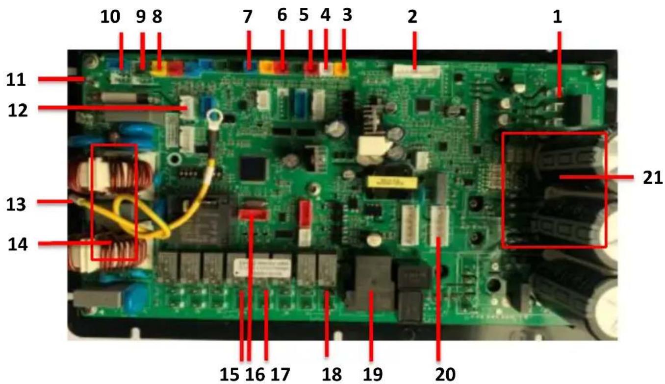
Figure 4-2.3: (GHP-MM10)/(GHP-MM12)
text_image
10 9 8 7 6 5 4 3 2 1 11 12 13 14 15 16 17 18 19 20 21Table 4-2.4: (GHP-MM10)/(GHP-MM12)
| Items | Port label | function |
| 1 U/V/W | Compressor output | |
| 2 JTAG Drive program update | update | |
| 3 TH1 Coil temperature sensor | ||
| 4 | TH2 | Outdoor ambient temperature sensor |
| 5 | TH3 | Refrigerant liquid temperature sensor |
| 6 | TH5 | Discharge temperature sensor |
| 7 | TH7 | Suction temperature sensor |
| 8 | TS3 | HP2: Middle pressure switch |
| 9 | TS4 | HP1: High pressure switch |
| 10 | TS5 | LPS: low pressure sensor |
| 11 AC Power supply | ||
| 12 | COM4 | Communication with hydraulic module PCB |
| 13 | PE1 | Port for ground |
| 14 / Filter components | ||
| 15 | OUT 4 | Four-way valve |
| 16 | FLS | PCB Program update |
| 17 OUT 5 Chassis heater | ||
| 18 | OUT 8 | Crankcase heater |
| 19 | K9 | Relay for PFC |
| 20 | FAN1 | DC fan |
| 21 / Drive components | ||
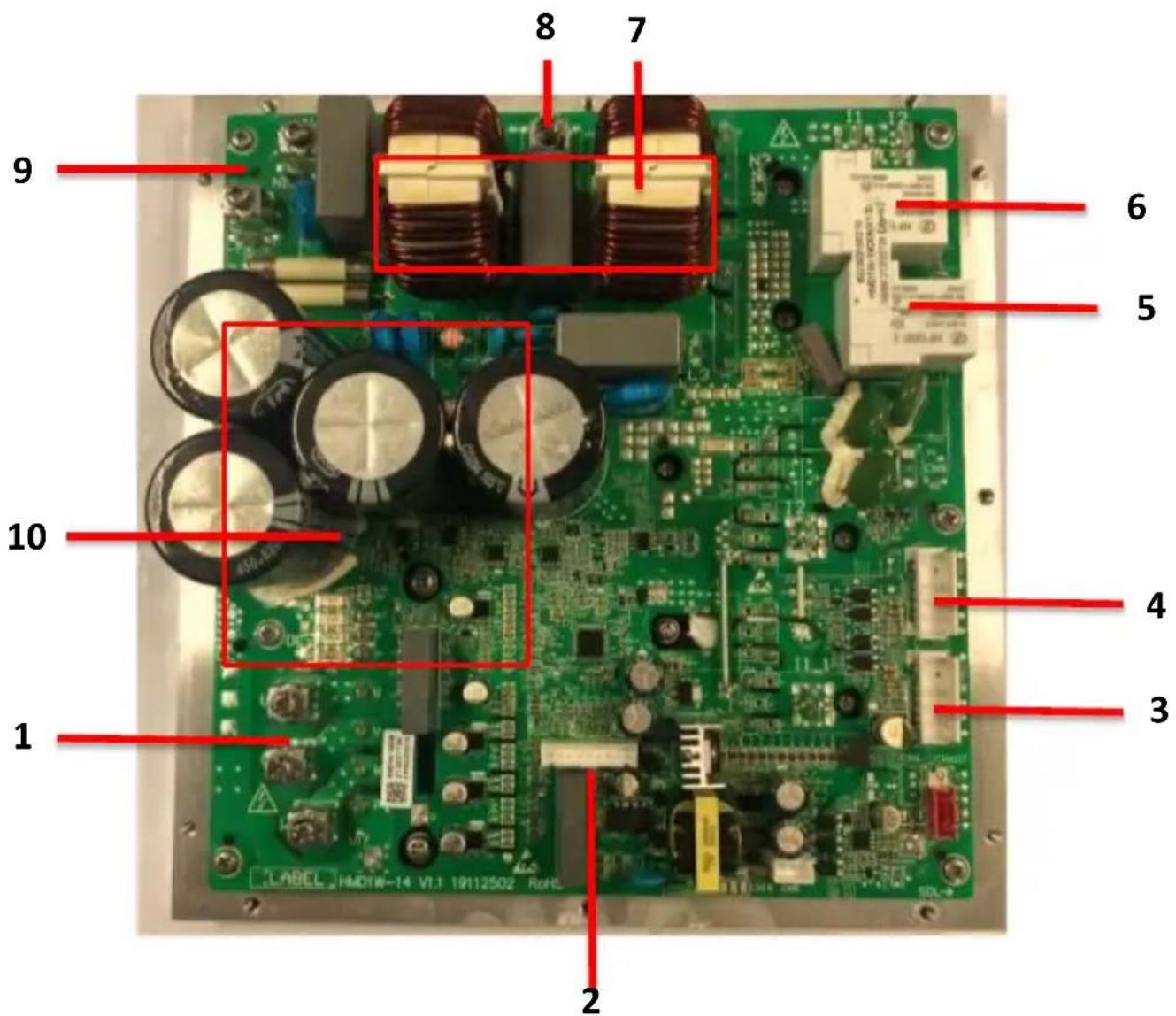
Figure 4-2.4: (GHP-MM14)/(GHP-MM16) Drive PCB
text_image
1 2 3 4 5 6 7 8 9 10 LABEL HMDTN-14 V1.1 19112502 R0FCTable 4-2.5: (GHP-MM14)/(GHP-MM16) Drive PCB
| Items | Port label | function |
| 1 U/V/W Compressor output | ||
| 2 | JTAG | Drive program update |
| 3 FAN1 DC fan | ||
| 4 FAN2 Reserved | ||
| 5 K2 Relay for PFC | ||
| 6 K1 Relay for PFC | ||
| 7 | / | Filter components |
| 8 PE Port for ground | ||
| 9 AC Power supply | ||
| 10 | / | Drive components |
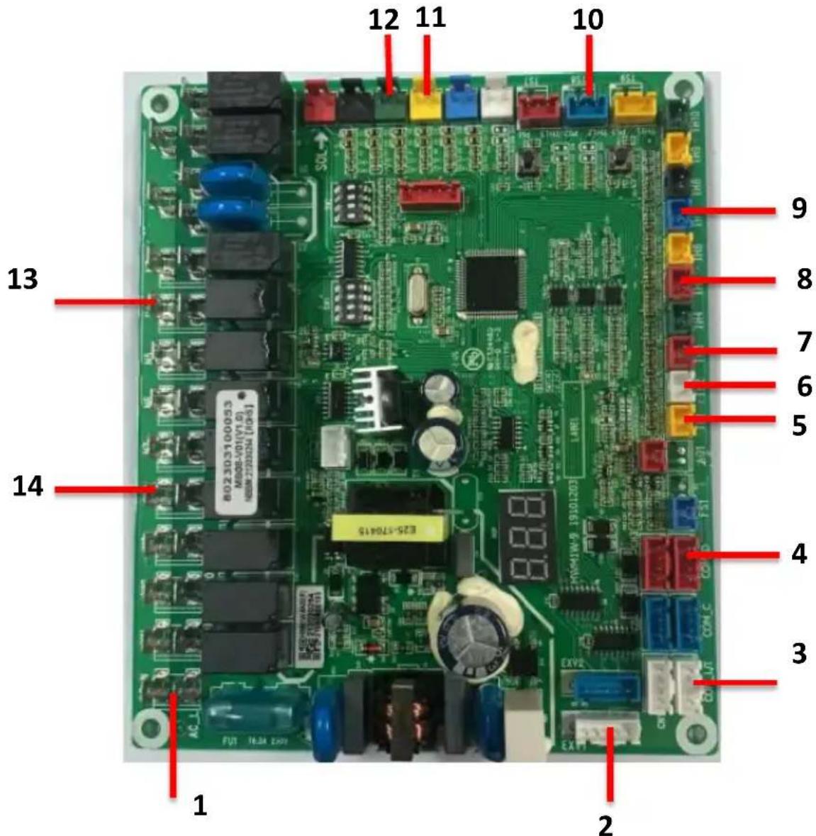
Figure 4-2.5: (GHP-MM14)/(GHP-MM16) Refrigerant System PCB
text_image
1 2 3 4 5 6 7 8 9 10 11 12 13 14 E25-CT0415 FUT 10.0kV 2.0kV MOS-V01(V1.0) HBM-72032N (10.0kV) EXV2 EXV1Table 4-2.6: (GHP-MM14)/(GHP-MM16)Refrigerant System PCB
| Items Port label function | ||
| 1 | AC (L/N) | Power supply |
| 2 | EXV1 | Electric expansive valve |
| 3 | COM_L/I | Communication with hydraulic module PCB |
| 4 | COM_D | Communication with inverter module PCB |
| 5 | TH1 | T3: Coil temperature sensor |
| 6 | TH2 | T4: Outdoor ambient temperature sensor |
| 7 | TH3 | T5: liquid temperature sensor |
| 8 | TH5 | TP: Discharge temperature sensor |
| 9 | TH7 | TH: Suction temperature sensor |
| 10 | TS8 | LPS: Low pressure sensor |
| 11 | TS4 | HP2: Middle pressure switch |
| 12 | TS3 | HP1: High pressure switch |
| 13 | Output 4 | Four-way valve |
| 14 | Output 8 | Crankcase heater |
4.3 Error Code Table
Table 4-3.1: Error code table
| Error code | Description Remark | |
| P01 | Water flow failure | |
| P02 | High refrigerant pressure protection | HP1, occurring during the operation |
| P03 | Low refrigerant pressure protection | |
| P04 | Coil overheating protection | T3 temp. is too high, only in cooling mode |
| P05 | High discharge temperature protection | TP temp. is too high |
| P06 | Too low outlet water temperature protection | TB temp. is too low, only in cooling mode |
| P07 | Too low Refrigerant Liquid temp. protection | T5 temp. is too low, only in cooling mode |
| P08 | Too high system pressure protection | HP2, occurring when the compressor is off |
| P10 | Low refrigerant pressure protection | Only cooling mode |
| P11 | DC fan 1 failure | |
| P12 | Reserved | |
| P13 | 4-way valve shifting failure | |
| P21 | Built-in DC water pump abnormal | |
| P24 | Reserved | |
| P25 | Outlet water pressure sensor error | |
| E01 | Communication error between hydraulic module PCB and the user interface | |
| E02 | Discharge temp. sensor error | TP sensor |
| E03 | Coil temp. sensor error | T3 sensor |
| E04 | Outdoor ambient temp. sensor error | T4 sensor |
| E05 | Refrigerant liquid temp. sensor error | T5 sensor |
| E06 | Suction temp. sensor error | TH sensor |
| E07 | Domestic water temp. sensor error | TW sensor |
| E08 | Inlet water temp. sensor error | TA sensor |
| E09 | Outlet water temp. sensor error | TB sensor |
| E10 | Communication between refrigerant system PCB and drive PCB failure | |
| E11 | Reserved | |
| E12 | Reserved | |
| E13 | Reserved | |
| E14 | Low pressure sensor error | Low pressure sensor: LPS |
| E15 | Too low DC bus voltage | |
| E16 | Too high DC bus voltage | |
| E17 | Too high AC input peak current | |
| E18 | Abnormal IPM module | |
| E19 | Abnormal PFC module | |
| E20 | Compressor startup failure | |
| E21 | Compressor phase loss error | |
| E22 | Inverter module Reset | E22 is a state which the compressor is resetting, no faulty |
| E23 | Too high compressor current protection | |
| E24 | Too high PFC module temp. protection | |
| E25 | The current detection circuit failure | |
| E26 | Out of step protection | |
| E27 | PFC module temp. sensor error | |
| E28 | Communication data error between refrigerant system PCB and inverter PCB | |
| E29 | Too high IPM module temp. | |
| E30 | IPM module temp. sensor error | |
| E31 | Reserved | |
| E32 | Inverter module debugging data | No error |
| E33 | Inverter module debugging data | No error |
| E34 | Abnormal AC input power supply | |
| E35 | Inverter module debugging data | No error |
| E36 | Reserved | |
| E37 | Module current limiting frequency No error | |
| E38 | Module voltage limiting frequency No error |
■ These codes are displayed on the user interface.
4.4 Troubleshooting
4.4.1 Warning

- Improper installation or attachment of equipment or accessories could result in electric shock, short-circuit, leaks, fires or other damage to the unit.
All electrical works must be carried out by competent and suitably qualified, certified and accredited professionals and in accordance with all applicable legislation (all national, local and other laws, standards, codes, rules, regulations and other legislation that apply in a given situation).
If unsure of installation procedures or use, always contact your dealer for advice and information.
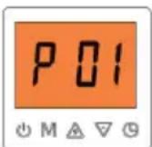
4.4.2 P01 diagnosis and analysis
4.4.2.1 Diagnosis
Code P01 means heat pump tripped with the open of the contactor of water flow switch installed on the port TS1 of hydraulic module PCB with too low water flow rate. When code P01 occurs three times within half an hour, a manual power-off must be done before heat pump can resume next restart.
4.4.2.2 Possible causes
■ Water flow switch wiring is loose or open.
■ Water flow rate is too low.
The components, such as water flow switch, water pump and hydraulic module PCB, are damaged.
4.4.2.3 Analysis and action
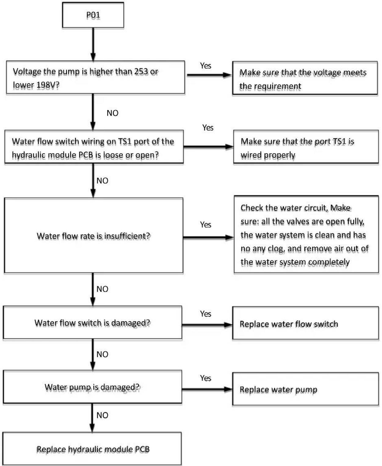
flowchart
graph TD
    A["P01"] --> B["Voltage the pump is higher than 253 or lower 198V?"]
    B -->|No| C["Water flow switch wiring on TS1 port of the hydraulic module PCB is loose or open?"]
    B -->|Yes| D["Make sure that the voltage meets the requirement"]
    C -->|No| E["Water flow rate is insufficient?"]
    C -->|Yes| F["Make sure that the port TS1 is wired properly"]
    E -->|No| G["Water flow switch is damaged?"]
    E -->|Yes| H["Check the water circuit, Make sure: all the valves are open fully, the water system is clean and has no any clog, and remove air out of the water system completely"]
    G -->|No| I["Water pump is damaged?"]
    G -->|Yes| J["Replace water flow switch"]
    I -->|No| K["Replace hydraulic module PCB"]
    I -->|Yes| L["Replace water pump"]
    J -->|Yes| M["Replace water pump"]
    J -->|No| N["Water flow switch is damaged?"]
4.4.3 P02 diagnosis and analysis
4.4.3.1 Diagnosis
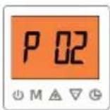
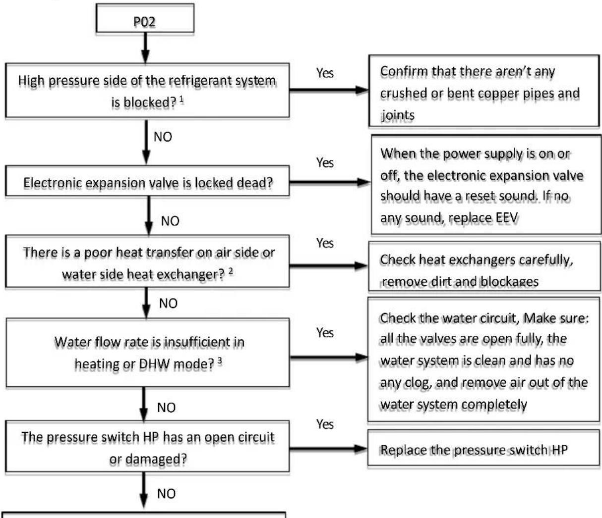
Code P02 means heat pump tripped with the open of the pressure switch (HP1, installed on the discharge pipe) contactor with too high pressure. When the discharge pressure rises above 4.5MPa, the pressure switch HP (labeled on the port TS3 of the refrigerant system PCB) opens and the interface will display the code P02 and heat pump will shut down. When discharge pressure drops below 3.5MPa, HP closes and Code P02 disappears, and heat pump will be ready for next startup.
4.4.3.2 Possible causes
■ Pressure switch HP is not connected properly or has malfunctioned.
■ Too much refrigerant in the system.
■ Refrigerant system contains non-condensable gas, such as air or nitrogen, etc.
■ High pressure side of the refrigerant system is clogged.
■ Poor heat transfer on heat exchanger on high pressure side.
■ Refrigerant system PCB is damaged.
4.4.3.3 Analysis and action
flowchart
graph TD
    A["P02"] --> B["High pressure side of the refrigerant system is blocked?¹"]
    B -->|NO| C["Electronic expansion valve is locked dead?"]
    B -->|Yes| D["Confirm that there aren't any crushed or bent copper pipes and joints"]
    C -->|NO| E["There is a poor heat transfer on air side or water side heat exchanger?²"]
    C -->|Yes| F["When the power supply is on or off, the electronic expansion valve should have a reset sound. If no any sound, replace EEV"]
    E -->|NO| G["Water flow rate is insufficient in heating or DHW mode?³"]
    E -->|Yes| H["Check heat exchangers carefully, remove dirt and blockages"]
    G -->|NO| I["The pressure switch HP has an open circuit or damaged?"]
    G -->|Yes| J["Check the water circuit, Make sure: all the valves are open fully, the water system is clean and has no any clog, and remove air out of the water system completely"]
    I -->|NO| K["No"]
    I -->|Yes| L["Replace the pressure switch HP"]
    J -->|No| K
    J -->|Yes| L
Replace refrigerant system PCB
Notes:
- The blockage of high pressure side of the refrigerant system will lead to higher discharge temperature, higher discharge pressure and lower suction pipe pressure.
- In heating and DHW mode check water side heat exchanger, water piping, circulator pumps and water flow switch for dirt and blockages. In cooling mode check air side heat exchanger, the fan and air outlets for dirt and blockages.
- Check the outlet pressure of the water system. If the pressure is lower than 1 bar, water flow rate is insufficient.
4.4.4 P03 diagnosis and analysis
4.4.4.1 Diagnosis
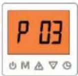
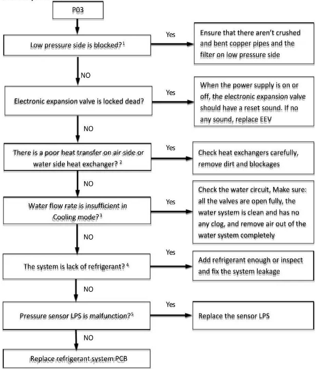
Code P03means heat pump tripped with too low pressure detected by LPS (the pressure sensor installed on the suction pipe of the compressor, labeled on the port TS8 of the refrigerant system PCB). When the suction pressure falls below 0.14MPa for ten seconds, the interface displays the code P03 and the heat pump will shut down. When the suction pressure rises above 0.30MPa, Code P03disappears and the heat pump will be ready for next startup. When code P03has occurred 3 times within an hour, a manual power-off must be done before heat pump can resume next restart.
4.4.4.2 Possible causes
■ The system is lack refrigerant.
There is a blockage on low pressure side of the refrigerant system.
There is a poor heat transfer on low pressure side of the refrigerant system.
■ The water flow rate is insufficient when running in cooling mode.
■ LPS is faulty.
■ The refrigerant system PCB is damaged.
4.4.4.3 Analysis and action
flowchart
graph TD
    A["P03"] --> B["Low pressure side is blocked?¹"]
    B -->|NO| C["Electronic expansion valve is locked dead?"]
    B -->|Yes| D["Ensure that there aren't crushed and bent copper pipes and the filter on low pressure side"]
    C -->|NO| E["There is a poor heat transfer on air side or water side heat exchanger?²"]
    C -->|Yes| F["When the power supply is on or off, the electronic expansion valve should have a reset sound. If no any sound, replace EEV"]
    E -->|NO| G["Water flow rate is insufficient in Cooling mode?³"]
    E -->|Yes| H["Check heat exchangers carefully, remove dirt and blockages"]
    G -->|NO| I["The system is lack of refrigerant?⁴"]
    G -->|Yes| J["Check the water circuit, Make sure: all the valves are open fully, the water system is clean and has no any clog, and remove air out of the water system completely"]
    I -->|NO| K["Pressure sensor LPS is malfunction?⁵"]
    I -->|Yes| L["Add refrigerant enough or inspect and fix the system leakage"]
    K -->|NO| M["Replace refrigerator system PCB"]
    K -->|Yes| N["Replace the sensor LPS"]
Notes:
-
Low pressure side blockages lead to higher discharge temperature, lower suction pressure, lower compressor current, and a frosting occurs on the suction pipe.
-
Check the air side heat exchanger, the fan and air outlets for dirt and blockages.
-
Check water side heat exchanger, water piping, circulator pumps and water flow switch for dirt and blockages.
-
The lack of refrigerant will lead to high discharge temperature, lower discharge and suction pressures and compressor current, and may frost on the suction pipe. These issues will disappear once sufficient refrigerant has been charged into the system.
-
Measure the resistance among the three terminals of the pressure sensor. If the resistance is of the order of mega Ohms or infinite, the pressure sensor has failed.
4.4.5 P04 diagnosis and analysis
4.4.5.1 Diagnosis
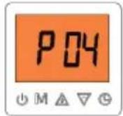
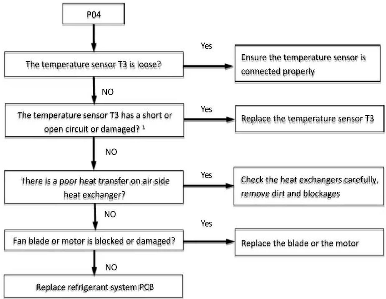
Code P04 is only possible in cooling mode. Code P04 means heat pump tripped with too high temperature detected by the temperature sensor T3 installed on refrigerant outlet liquid pipe of the air side heat exchanger only running on cooling mode. When the temperature detected by the sensor T3 is higher than 65°C for more than one minute, the interface displays the code P04 and heat pump will shut down. When the temperature detected by the sensor T3 drops below 52°C, Code P04 disappears and heat pump will be ready for next startup.
4.4.5.2 Possible causes
■ Temperature sensor T3 is not connected properly or has malfunctioned.
■ Poor heat transfer on air side heat exchange.
■ The motor or blades of the fan is damaged.
■ Refrigerant system PCB damaged.
4.4.5.3 Analysis and action
flowchart
graph TD
    A["P04"] --> B["The temperature sensor T3 is loose?"]
    B -->|No| C["The temperature sensor T3 has a short or open circuit or damaged?\( ^1 \)"]
    B -->|Yes| D["Ensure the temperature sensor is connected properly"]
    C -->|No| E["There is a poor heat transfer on air side heat exchanger?"]
    C -->|Yes| F["Replace the temperature sensor T3"]
    E -->|No| G["Fan blade or motor is blocked or damaged?"]
    E -->|Yes| H["Check the heat exchangers carefully, remove dirt and blockages"]
    G -->|No| I["Replace refrigerant system PCB"]
    G -->|Yes| J["Replace the blade or the motor"]
Note:
- Measure sensor resistance. If the resistance is too low, the sensor has short-circuited. If the resistance is not consistent with the sensor's resistance characteristic table, the sensor has failed. Refer to Part 4, 4-5.1 "Temperature Sensor Resistance Characteristics".
4.4.6 P05 diagnosis and analysis
4.4.6.1 Diagnosis
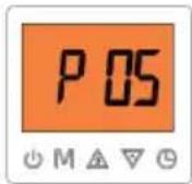
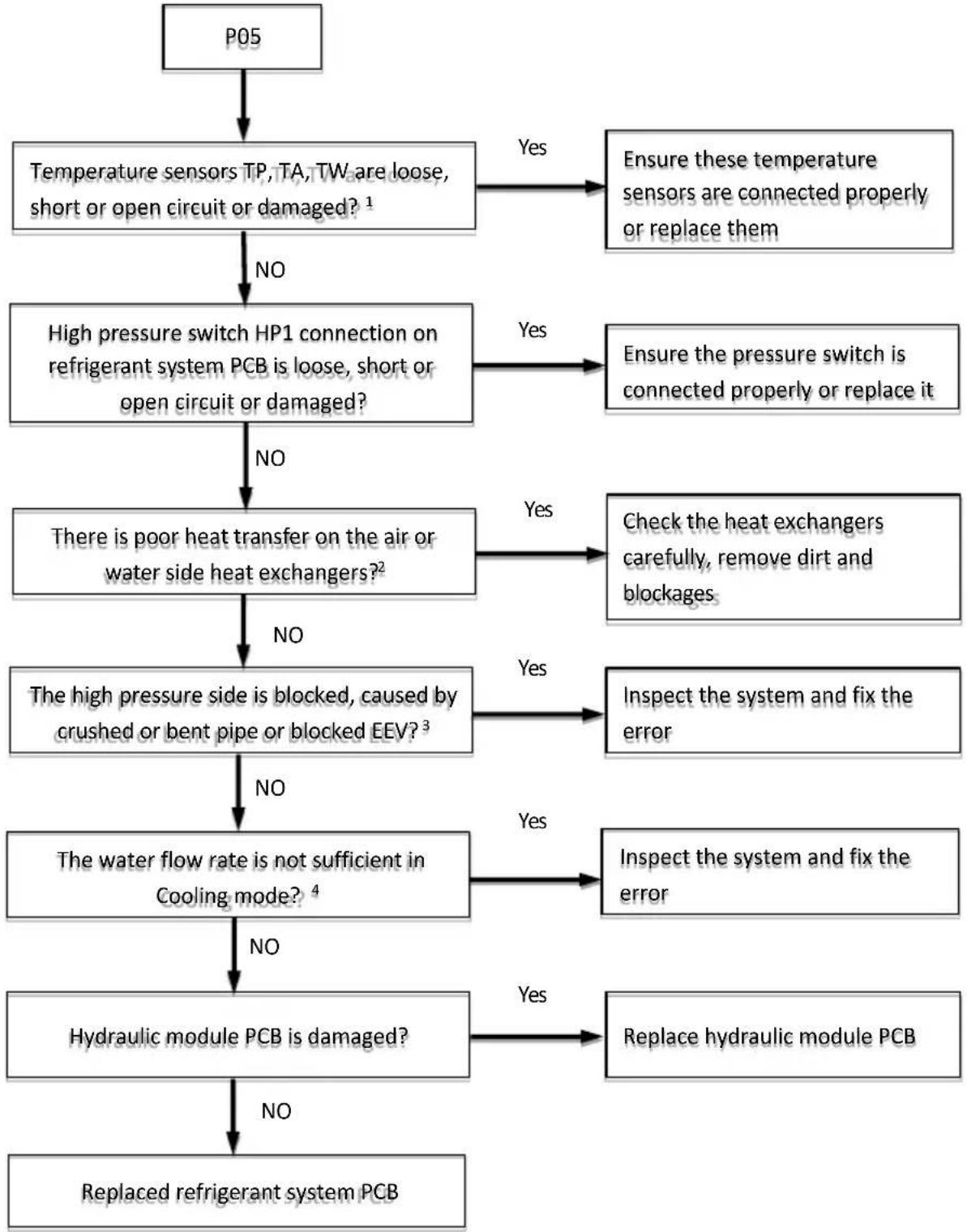
Code P05 means heat pump tripped with too high temperature detected by the temperature sensor TP installed on the discharge pipe of the compressor outlet. When outdoor ambient temperature T4 is below minus 15°C and the temperature detected by TP is higher than 115°C for more than 30 seconds, or When outdoor ambient temperature T4 is above minus 15°C and the temperature detected by TP is higher than 110°C for more than 30 seconds, the interface will display code P05 and heat pump will shut down. After 10 minutes, the compressor is allowed to start again when TP drops below 90°C, Code P05 will disappears and heat pump will be ready for next startup.
4.4.6.2 Possible causes
■ Temperature sensor TP is error.
■ High pressure side blockage.
■ Poor condenser heat exchange.
■ Refrigerant system PCB is damaged.
4.4.6.3 Analysis and action
flowchart
graph TD
    A["P05"] --> B["Temperature sensors TP, TA, TW are loose, short or open circuit or damaged? 1"]
    B -->|NO| C["High pressure switch HP1 connection on refrigerant system PCB is loose, short or open circuit or damaged?"]
    C -->|NO| D["There is poor heat transfer on the air or water side heat exchangers?2"]
    C -->|Yes| E["Ensure these temperature sensors are connected properly or replace them"]
    D -->|NO| F["The high pressure side is blocked, caused by crushed or bent pipe or blocked EEV?3"]
    D -->|Yes| G["Check the heat exchangers carefully, remove dirt and blockages"]
    F -->|NO| H["The water flow rate is not sufficient in Cooling mode? 4"]
    F -->|Yes| I["Inspect the system and fix the error"]
    H -->|NO| J["Hydraulic module PCB is damaged?"]
    H -->|Yes| K["Replace hydraulic module PCB"]
    J -->|NO| L["Replaced refrigerant system PCB"]
    J -->|Yes| M["Replace hydraulic module PCB"]
Notes:
- Measure sensor resistance. If the resistance is too low, the sensor has short-circuited. If the resistance is not consistent with the sensor's resistance characteristic table, the sensor has failed. Refer to Part 4. 4-5.1 "Temperature Sensor Resistance Characteristics".
- Check air or water side heat exchanger, the fan and air outlets for dirt and blockages.
- High pressure side blockage causes discharge temperature to be higher than normal, discharge pressure to be higher than normal and suction pressure to be lower than normal.
- Check the water side heat exchanger, water piping, circulator pumps and water flow switch for dirt and blockages.
4.4.7 P06 diagnosis and analysis
4.4.7.1 Diagnosis
Code P06 is only possible in cooling mode. CodeP06 means heat pump tripped with too low outlet water temperature detected by the temperature sensor TB installed on the outlet pipe of water side heat exchanger. If TB has been lower than 4°C for 120 seconds, Heat pump will shut down and the interface will display the faulty code P06. When TB is above 8°C for one minute, Heat pump will be ready for next startup.
4.4.7.2 Possible causes
■ Temperature sensor TB isn't connected properly or has malfunctioned.
■ Hydraulic module PCB damaged.
4.4.7.3 Analysis and action
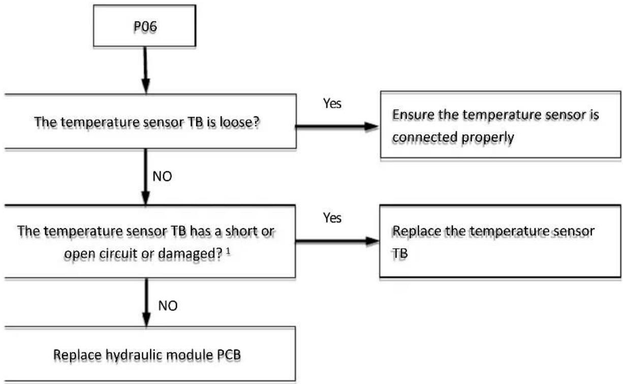
flowchart
graph TD
    A["P06"] --> B["The temperature sensor TB is loose?"]
    B -->|Yes| C["Ensure the temperature sensor is connected properly"]
    B -->|NO| D["The temperature sensor TB has a short or open circuit or damaged?¹"]
    D -->|Yes| E["Replace the temperature sensor TB"]
    D -->|NO| F["Replace hydraulic module PCB"]
Note:
- Measure sensor resistance. If the resistance is too low, the sensor has short-circuited. If the resistance is not consistent with the sensor's resistance characteristic table, the sensor has failed. Refer to Part 4, 4-5.1 "Temperature Sensor Resistance Characteristics".
4.4.8 P07 diagnosis and analysis
4.4.8.1 Diagnosis
Code P07 is only possible in cooling mode. Code P07 means heat pump tripped with too low outlet temperature detected by the temperature sensor T5 installed on the outlet pipe of electronic expansion valve in cooling mode. If T5 has been lower than 2°C for 120 seconds, Heat pump will shut down and the interface will display the faulty code P06. When T5 is above 8°C for ten minutes, Heat pump will be ready for next startup.
4.4.8.2 Possible causes
■ Temperature sensor T5 isn't connected properly or has malfunctioned.
■ Refrigerant system PCB is damaged.
4.4.8.3 Analysis and action
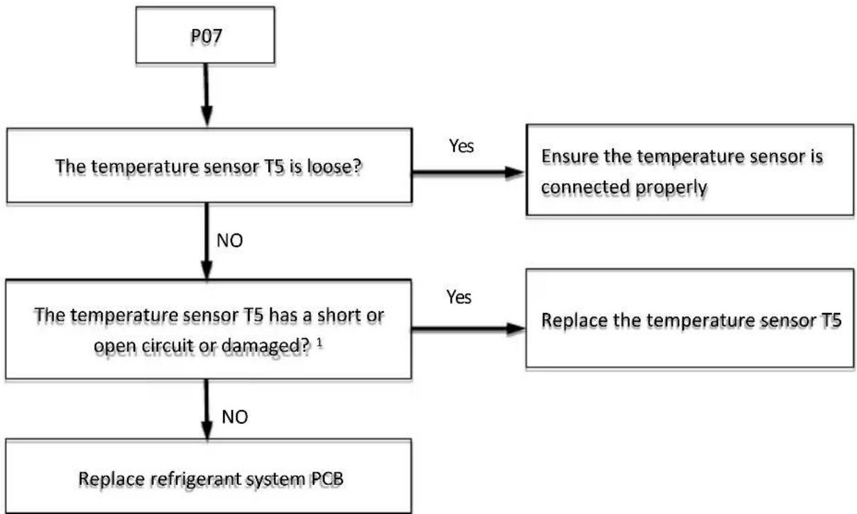
flowchart
graph TD
    A["P07"] --> B["The temperature sensor T5 is loose?"]
    B -->|Yes| C["Ensure the temperature sensor is connected properly"]
    B -->|NO| D["The temperature sensor T5 has a short or open circuit or damaged? 1"]
    D -->|Yes| E["Replace the temperature sensor T5"]
    D -->|NO| F["Replace refrigerant system PCB"]
Note:
- Measure sensor resistance. If the resistance is too low, the sensor has short-circuited. If the resistance is not consistent with the sensor's resistance characteristic table, the sensor has failed. Refer to Part 4, 4-5.1 "Temperature Sensor Resistance Characteristics".
4.4.9 P08 diagnosis and analysis
4.4.9.1 Diagnosis
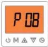
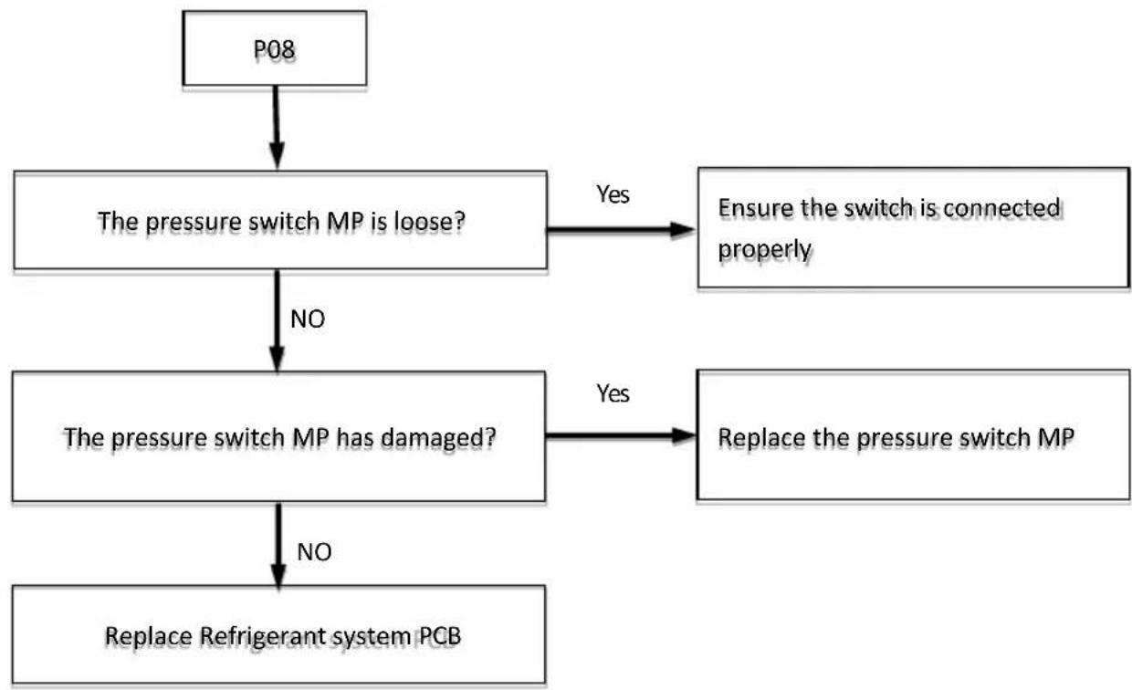
When Heat pump shuts down and the contactor of the middle pressure switch MP installed on the discharge pipe of the compressor keeps open for 3 seconds, the interface will display the code P08 and heat pump still keeps in the shutdown state until the contactor of the pressure switch HP2 closes. When the pressure is above 4.2MPa, the contactor of the middle pressure switch MP will open. When the pressure is below 3.8MPa, the contactor will close.
4.4.9.2 Possible causes
■ The port TS4 of the pressure switch MP (Middle Pressure) on refrigerant system PCB is not connected properly or has malfunctioned.
■ Refrigerant system PCB is damaged.
4.4.9.3 Analysis and action
flowchart
graph TD
    A["P08"] --> B["The pressure switch MP is loose?"]
    B -->|Yes| C["Ensure the switch is connected properly"]
    B -->|NO| D["The pressure switch MP has damaged?"]
    D -->|Yes| E["Replace the pressure switch MP"]
    D -->|NO| F["Replace Refrigerant system PCB"]
4.4.10 P10 diagnosis and analysis
4.4.10.1 Diagnosis
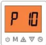
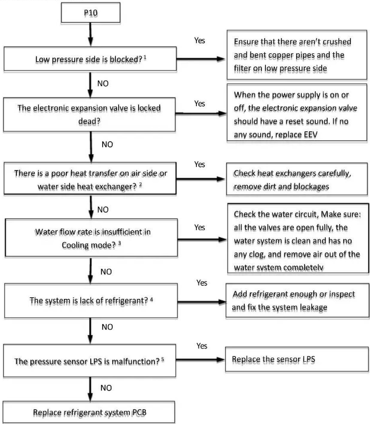
After heat pump run for one minute in cooling mode, if the pressure detected by LPS is below 0.7MPa for 2 minutes, heat pump will shut down and the interface will display the code P10. In ten minutes heat pump will be allowed to start again. If Code P10 occurred for three times within one hour, heat pump will shut down. A manual power-off must be done before next restart.
4.4.10.2 Possible causes
■ The system is lack of refrigerant.
There is the blockage on low pressure side of the refrigerant system.
There is a poor heat transfer on low pressure side of the refrigerant system.
■ Water flow rate is insufficient.
■ LPS is faulty.
■ Refrigerant system PCB is damaged.
4.4.10.3 Analysis and action
flowchart
graph TD
    A["P10"] --> B["Low pressure side is blocked?¹"]
    B -->|NO| C["The electronic expansion valve is locked dead?"]
    B -->|Yes| D["Ensure that there aren't crushed and bent copper pipes and the filter on low pressure side"]
    C -->|NO| E["There is a poor heat transfer on air side or water side heat exchanger?²"]
    C -->|Yes| F["When the power supply is on or off, the electronic expansion valve should have a reset sound. If no any sound, replace EEV"]
    E -->|NO| G["Water flow rate is insufficient in Cooling mode?³"]
    E -->|Yes| H["Check heat exchangers carefully, remove dirt and blockages"]
    G -->|NO| I["The system is lack of refrigerant?⁴"]
    G -->|Yes| J["Check the water circuit, Make sure: all the valves are open fully, the water system is clean and has no any clog, and remove air out of the water system completely"]
    I -->|NO| K["The pressure sensor LPS is malfunction?⁵"]
    I -->|Yes| L["Add refrigerant enough or inspect and fix the system leakage"]
    K -->|NO| M["Replace refrigerator system PCB"]
    K -->|Yes| N["Replace the sensor LPS"]
Notes:
-
Low pressure side blockages lead to higher discharge temperature, lower suction pressure, lower compressor current, and a frosting to occur on the suction pipe.
-
Check air side heat exchanger, the fan and air outlets for dirt and blockages.
-
Check water side heat exchanger, water piping, circulator pumps and water flow switch for dirt and blockages.
-
The lack of refrigerant will lead to high discharge temperature, lower discharge and suction pressures and compressor current, and may frost on the suction pipe. These issues will disappear once sufficient refrigerant has been charged into the system.
-
Measure the resistance among the three terminals of the pressure sensor. If the resistance is of the order of mega ohms or infinite, the pressure sensor has failed.
4.4.11 P11 diagnosis and analysis
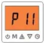
4.4.11.1 Diagnosis
Code P11 indicates a DC fan error. If Code P11 occurred ten times within two hours, heat pump will shut down. A manual power-off restart must be done before next startup. P11 error should be addressed promptly in order to protect heat pump from being damaged.
4.4.11.2 Possible causes
■ Power or communication wires are not connected properly.
■ High wind speed.
■ Fan motor blocked or has malfunctioned.
■ Abnormal power supply.
■ Drive PCB is damaged.
4.4.11.3 Analysis and action
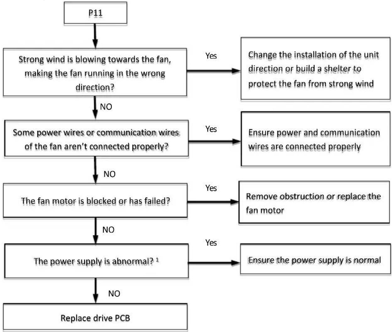
flowchart
graph TD
    A["P11"] --> B["Strong wind is blowing towards the fan, making the fan running in the wrong direction?"]
    B -->|No| C["Some power wires or communication wires of the fan aren't connected properly?"]
    B -->|Yes| D["Change the installation of the unit direction or build a shelter to protect the fan from strong wind"]
    C -->|No| E["The fan motor is blocked or has failed?"]
    C -->|Yes| F["Ensure power and communication wires are connected properly"]
    E -->|No| G["The power supply is abnormal?\( ^{1} \)"]
    E -->|Yes| H["Remove obstruction or replace the fan motor"]
    G -->|No| I["Replace drive PCB"]
    G -->|Yes| J["Ensure the power supply is normal"]
Note:
- For single-phase power supply models, check the voltage between "DC+" and "DC-" on the inverter module PCB. The normal range is 277V to 354V. If the voltage is outside this range, the inverter module PCB is damaged.
4.4.12 P13 diagnosis and analysis
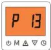
4.4.12.1 Diagnosis
When heat pump operates in heating or DHW mode, if “the inlet water temperature TA is higher than the outlet water temperature TB” is detected for 60 seconds, the heat pump will stop but the interface doesn’t display the code P13. After 3 minutes, heat pump will restart. If such “stop first and then restart” happened three times in succession, heat pump will trip and locked, the interface will display the code P13. A manual power-off must be done before next restart.
4.4.12.2 Possible causes
■ The system is lack of refrigerant.
■ The body of 4-way valve is locked.
■ The coil of 4-way valve malfunctioned.
■ 4-way valve is powered off.
■ Refrigerant system PCB is damaged.
4.4.12.3 Analysis and action
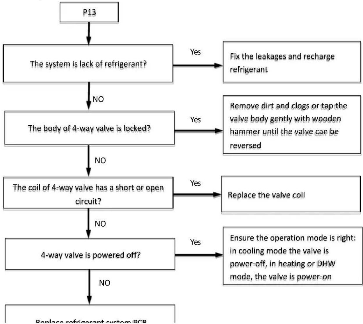
flowchart
graph TD
    A["P13"] --> B["The system is lack of refrigerant?"]
    B -->|Yes| C["Fix the leakages and recharge refrigerant"]
    B -->|NO| D["The body of 4-way valve is locked?"]
    D -->|Yes| E["Remove dirt and clogs or tap the valve body gently with wooden hammer until the valve can be reversed"]
    D -->|NO| F["The coil of 4-way valve has a short or open circuit?"]
    F -->|Yes| G["Replace the valve coil"]
    F -->|NO| H["4-way valve is powered off?"]
    H -->|Yes| I["Ensure the operation mode is right: in cooling mode the valve is power-off, in heating or DHW mode, the valve is power-on"]
    H -->|NO| J["Replace refrigerator system PCB"]
4.4.13 P21 diagnosis and analysis
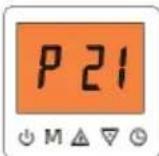
4.4.13.1 Diagnosis
Code P21 indicates built-in DC water pump worked itself abnormally.
4.4.13.2 Possible causes
■ Pump power off.
■ Pump power supply is abnormal.
■ Pump PWM output interface damaged.
■ Pump is stopped due to permanent failure.
4.4.12.3 Analysis and action
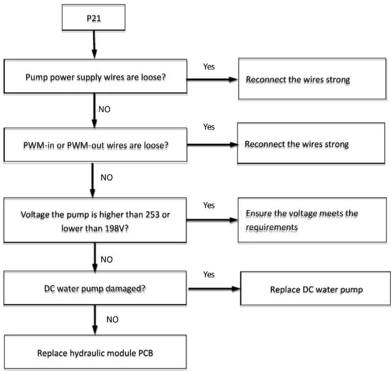
flowchart
graph TD
    A["P21"] --> B["Pump power supply wires are loose?"]
    B -->|No| C["PWM-in or PWM-out wires are loose?"]
    B -->|Yes| D["Reconnect the wires strong"]
    C -->|No| E["Voltage the pump is higher than 253 or lower than 198V?"]
    C -->|Yes| F["Reconnect the wires strong"]
    E -->|No| G["DC water pump damaged?"]
    E -->|Yes| H["Ensure the voltage meets the requirements"]
    G -->|No| I["Replace hydraulic module PCB"]
    G -->|Yes| J["Replace DC water pump"]
4.4.14 P25 diagnosis and analysis
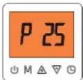
4.4.14.1 Diagnosis
Code P25 indicates outlet water pressure sensor had an error. If there are no other errors except for the water pressure sensor error, Heat pump will continue to operate.
4.4.14.2 Possible causes
■ Outlet water pressure sensor is not connected properly
■ Outlet water pressure sensor has malfunctioned.
4.4.14.3 Analysis and action
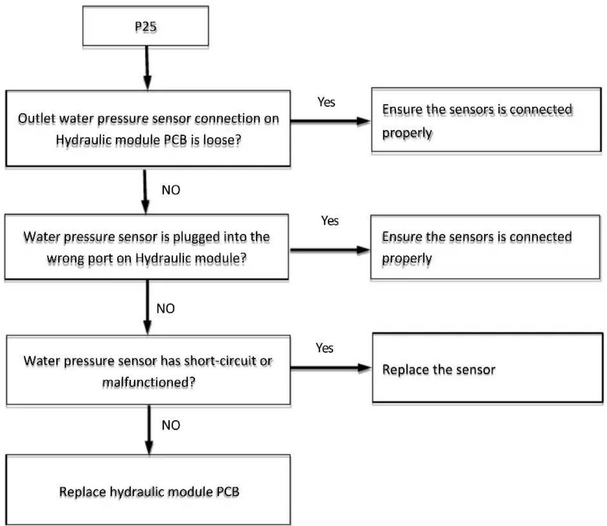
flowchart
graph TD
    A["P25"] --> B["Outlet water pressure sensor connection on Hydraulic module PCB is loose?"]
    B -->|No| C["Water pressure sensor is plugged into the wrong port on Hydraulic module?"]
    B -->|Yes| D["Ensure the sensors is connected properly"]
    C -->|No| E["Water pressure sensor has short-circuit or malfunctioned?"]
    C -->|Yes| F["Ensure the sensors is connected properly"]
    E -->|No| G["Replace hydraulic module PCB"]
    E -->|Yes| H["Replace the sensor"]
4.4.15 E01 diagnosis and analysis
4.4.15.1 Diagnosis
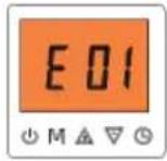
Code E01 indicates heat pump shut down because of the communication error between hydraulic module PCB and the user interface.
4.4.15.2 Possible causes
■ Communication wires between outdoor unit and user interface are not connected properly.
■ Communication wiring A and B terminals is disconnected.
■ Loosened wiring within the electric control box.
■ Interference from high voltage wires or other sources of electromagnetic radiation.
■ Damaged main PCB or electric control box communication terminals block.
4.4.15.3 Analysis and action
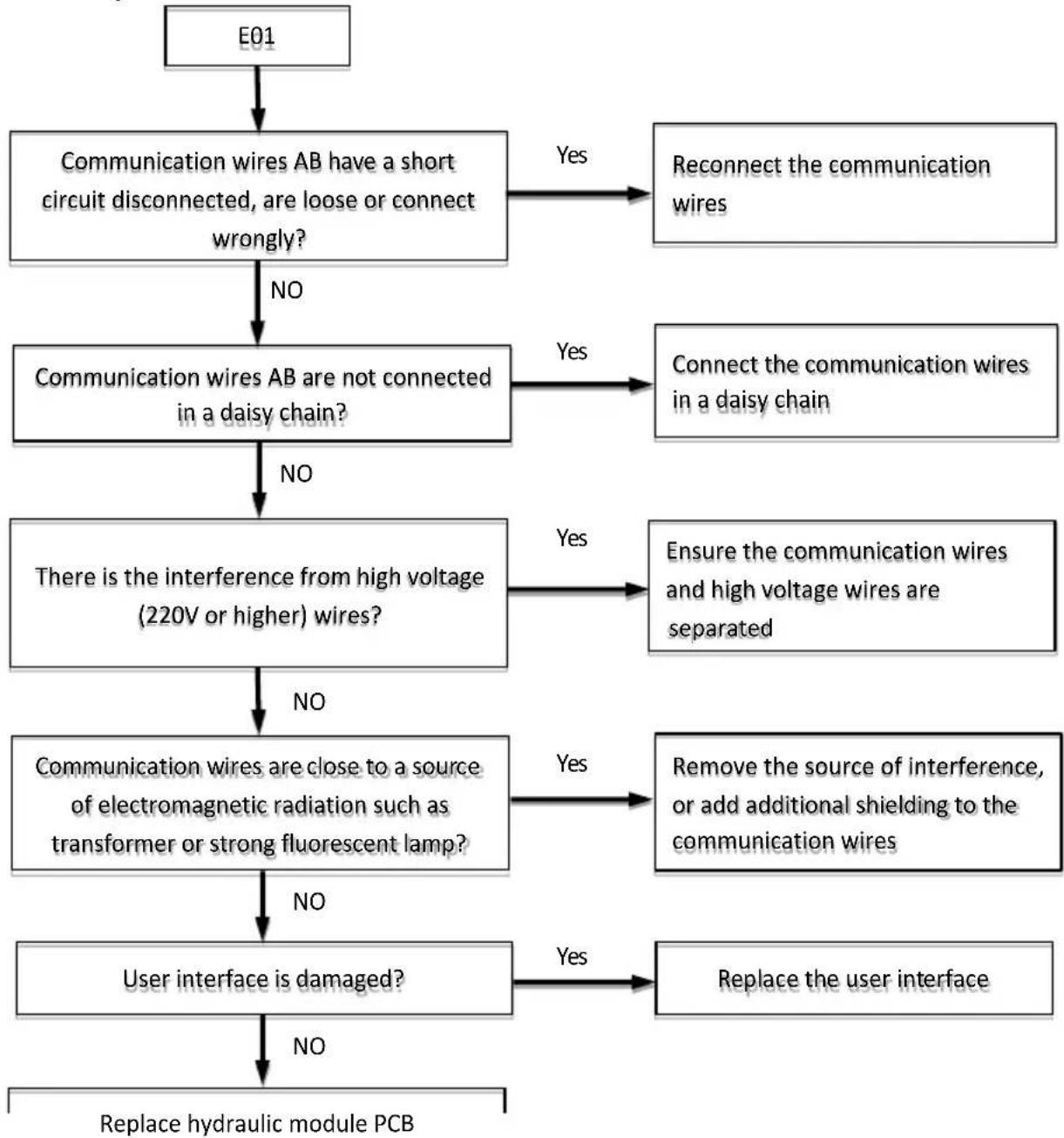
flowchart
graph TD
    A["E01"] --> B["Communication wires AB have a short circuit disconnected, are loose or connect wrongly?"]
    B -->|No| C["Communication wires AB are not connected in a daisy chain?"]
    B -->|Yes| D["Reconnect the communication wires"]
    C -->|No| E["There is the interference from high voltage (220V or higher) wires?"]
    C -->|Yes| F["Connect the communication wires in a daisy chain"]
    E -->|No| G["Communication wires are close to a source of electromagnetic radiation such as transformer or strong fluorescent lamp?"]
    E -->|Yes| H["Ensure the communication wires and high voltage wires are separated"]
    G -->|No| I["User interface is damaged?"]
    G -->|Yes| J["Remove the source of interference, or add additional shielding to the communication wires"]
    I -->|No| K["Replace hydraulic module PCB"]
    I -->|Yes| L["Replace the user interface"]
4.4.16 E02 E03 E04 E05 E06 E07 E08 E09 diagnosis and analysis

text_image
E 02 M △ ▽ ⏻ E 03 M △ ▽ ⏻ E 04 M △ ▽ ⏻ E 05 M △ ▽ ⏻ E 06 M △ ▽ ⏻ E 07 M △ ▽ ⏻ E 08 M △ ▽ ⏻ E 09 M △ ▽ ⏻4.4.16.1 Diagnosis
These codes indicate heat pump shut down because of the error of temperature sensors.
■ E02 indicates discharge temperature sensor TP appeared an error.
■ E03 indicates coil temperature sensor T3 appeared an error.
■ E04 indicates outdoor ambient temperature sensor T4 appeared an error.
■ E05 indicates liquid temperature sensor T5appeared an error.
■ E06 indicates suction temperature sensor TH appeared an error.
■ E07 indicates domestic water tank temperature sensor TW appeared an error.
■ E08 indicates inlet water temperature sensor TA appeared an error.
■ E09 indicates outlet water temperature sensor TB appeared an error.
4.4.16.2 Possible causes
■ Temperature sensors are not connected properly or have malfunctioned.
■ Refrigerant system PCB or hydraulic module PCB is damaged.
4.4.16.3 Analysis and action
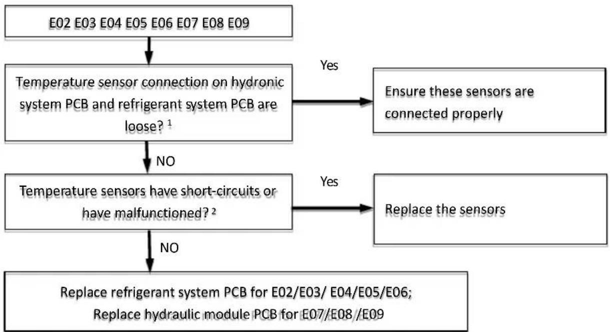
flowchart
graph TD
    A["E02 E03 E04 E05 E06 E07 E08 E09"] --> B["Temperature sensor connection on hydronic system PCB and refrigerant system PCB are loose?¹"]
    B -->|Yes| C["Ensure these sensors are connected properly"]
    B -->|NO| D["Temperature sensors have short-circuits or have malfunctioned?²"]
    D -->|Yes| E["Replace the sensors"]
    D -->|NO| F["Replace refrigerant system PCB for E02/E03/ E04/E05/E06; Replace hydraulic module PCB for E07/E08/E09"]
Notes:
-
Refer to Part 3, 7 Figure 3-7.1 for the location of temperature sensors.
-
Measure sensor resistance. If the resistance is too low, the sensor has short-circuited. If the resistance is not consistent with the sensor's resistance characteristics table, the sensor has failed. Refer to Part 4, 4-5.1 "Temperature Sensor Resistance Characteristics" for the resistance of sensors.
4.4.17 E10 diagnosis and analysis
4.4.17.1 Diagnosis
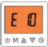
Code E10 indicates heat pump shut down because of the communication error between refrigerant system PCB chip and hydraulic module PCB chip.
4.4.17.2 Possible causes
■ Power supply abnormal.
■ Transformer malfunction.
■ Interference from a source of electromagnetic radiation.
■ Refrigerant system PCB or hydraulic module PCB damaged
4.4.17.3 Analysis and action
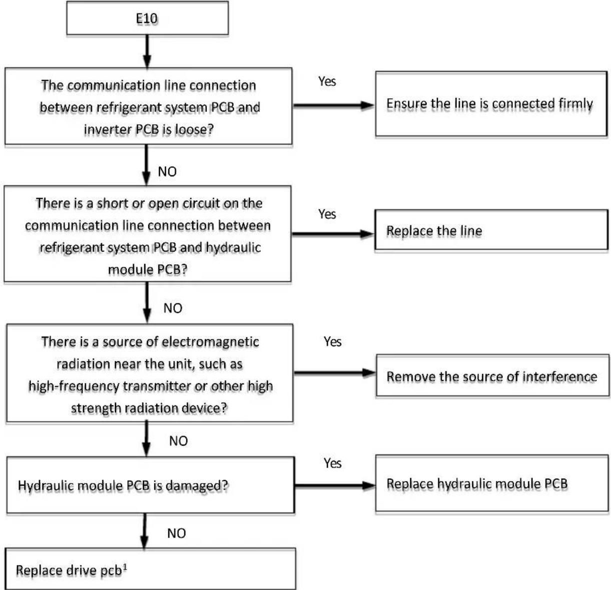
flowchart
graph TD
    A["E10"] --> B["The communication line connection between refrigerant system PCB and inverter PCB is loose?"]
    B -->|No| C["There is a short or open circuit on the communication line connection between refrigerant system PCB and hydraulic module PCB?"]
    B -->|Yes| D["Ensure the line is connected firmly"]
    C -->|No| E["There is a source of electromagnetic radiation near the unit, such as high-frequency transmitter or other high strength radiation device?"]
    C -->|Yes| F["Replace the line"]
    E -->|No| G["Hydraulic module PCB is damaged?"]
    E -->|Yes| H["Remove the source of interference"]
    G -->|No| I["Replace drive pcb¹"]
    G -->|Yes| J["Replace hydraulic module PCB"]
Note:
- For 14/16kW models, replace refrigerant system PCB. For 8/10/12Kw models, replace drive PCB.
4.4.18 E14 diagnosis and analysis
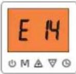
4.4.18.1 Diagnosis
Code E14 indicates heat pump shut down because of the error of low pressure sensor LPS.
4.4.18.2 Possible causes
■ Low pressure sensor is not connected properly
■ Low pressure sensor has malfunctioned.
4.4.18.3 Analysis and action
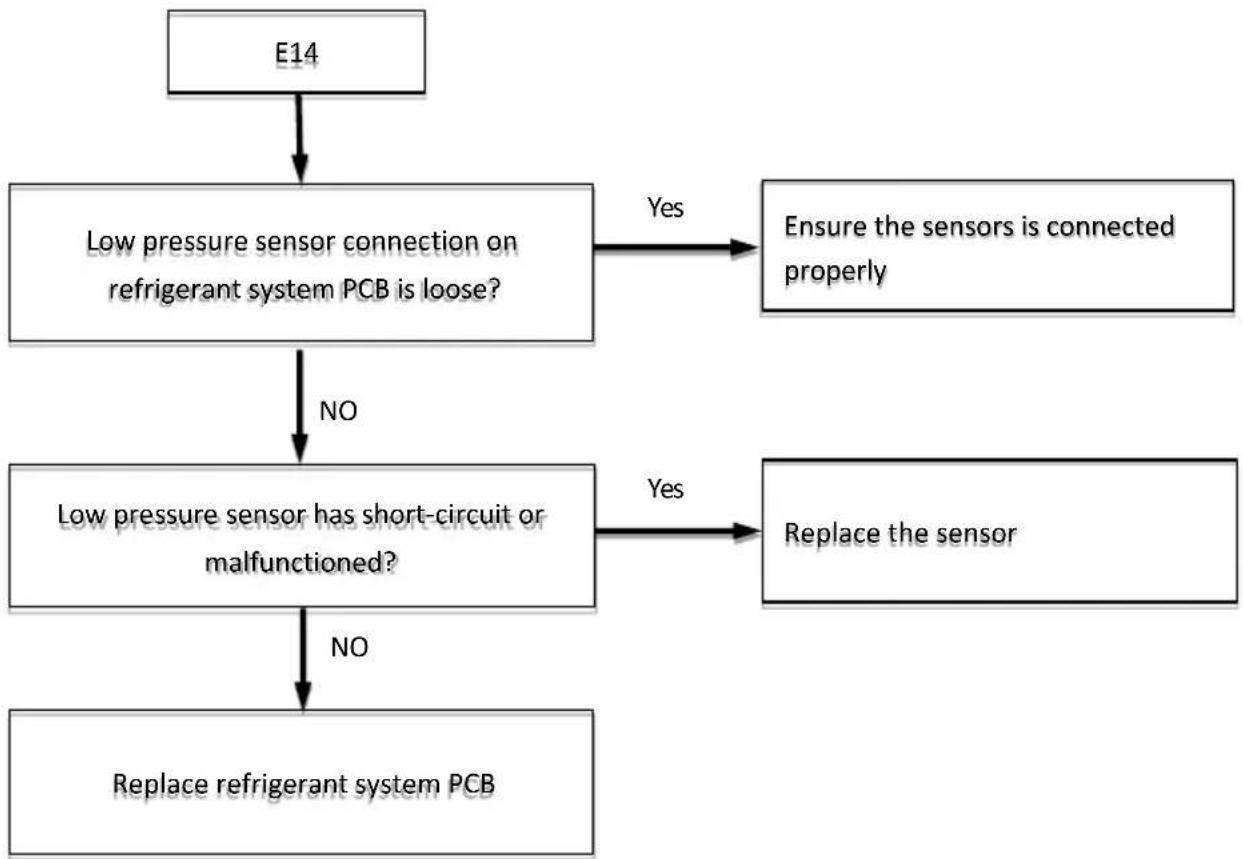
flowchart
graph TD
    A["E14"] --> B["Low pressure sensor connection on refrigerant system PCB is loose?"]
    B -->|Yes| C["Ensure the sensors is connected properly"]
    B -->|NO| D["Low pressure sensor has short-circuit or malfunctioned?"]
    D -->|Yes| E["Replace the sensor"]
    D -->|NO| F["Replace refrigerant system PCB"]
4.4.19 Inverter module troubleshooting for single-phase models
4.4.19.1 Codes
The codes displayed on the user interface are below: E15, E16, E17, E18, E19, E20, E21, E22, E23, E24, E25, E26, E27, E28, E29, E30, E31, E32, E33, E34, E35, E36, E37, and E38. Refer to Table 4-19.1 for these codes.
Table 4-19.1 Table of codes
| Error code | Content D1(RED) | ^2 D2(GREEN) ^2 D3(YELLOW) ^2 | ||
| E15 | Too low DC bus voltage | OFF | ON | ON |
| E16 | Too high DC bus voltage | Flash | ON | ON |
| E17 | Too high AC input peak current | OFF | Flash | ON |
| E18 | Abnormal IPM module | ON | Flash | OFF |
| E19 | Abnormal PFC module | OFF | ON | Flash |
| E20 | Compressor startup failure | ON | ON | Flash |
| E21 | Compressor phase loss error | ON | Flash | ON |
| E22^1 | Inverter module reset | / / | / | |
| E23 | Too high compressor current protection | Flash Flash Flash | ||
| E24 | Too high PFC module temp. protection | Flash | ON | Flash |
| E25 | The current detection circuit failure | ON | ON | OFF |
| E26 | Out of step protection | ON | ON | ON |
| E27 | PFC module temp. sensor error | Flash | ON | OFF |
| E28 | Communication data error between refrigerant system PCB and inverter PCB | Flash Flash OFF | ||
| E29 | Too high IPM module temp | ON | Flash | Flash |
| E30 | IPM module temp. sensor error | ON | OFF | Flash |
| E32^1 | Inverter module debugging data | / | / | / |
| E33^1 | Inverter module debugging data | / | / | / |
| E34 | Abnormal AC input power supply | Flash | OFF | ON |
| E35^1 | Inverter module debugging data | / | / | / |
| E37^1 | Module current limiting frequency | / | / | / |
| E38^1 | Module voltage limiting frequency | / | / | / |
Note:
1. E22、E32、E33、E35、E37 and E38 are not errors and heat pump does not shut down. The other codes are all errors, heat pump will shut down.
2. The combination of the show states of 3 led lights corresponds to different error codes. In standby: D1-OFF, D2-Flash and D3-OFF; In normal operation: D1-Flash, D2-OFF and D3-OFF. Refer to Figure 4-19.1 and Figure 4-19.2 for the location of each led.
Figure 4-19.1 Location of 3 led lights on the inverter module PCB for 8/10/12kW :
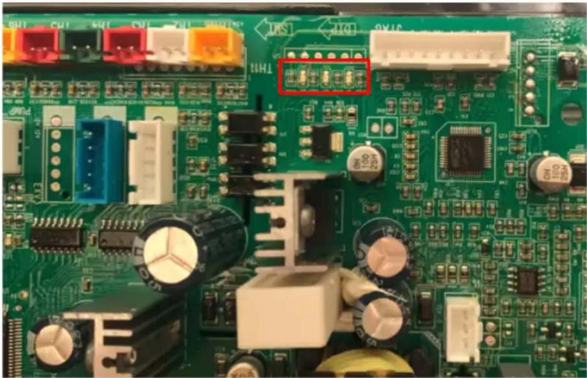
natural_image
Close-up of a green printed circuit board with various electronic components and connectors (no readable text or symbols)Figure 4-19.2 Location of 3 led lights on the inverter module PCB for 14/16kW:
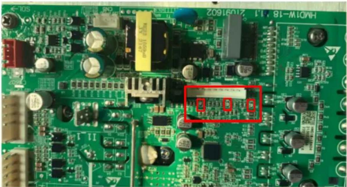
text_image
HMB1W-18 M1.2 21091602 50L4.4.19.3 Principle of DC inverter
Figure 4-19.3 Principle of DC inverter
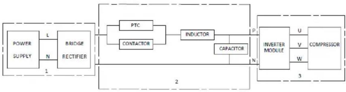
flowchart
graph LR
    A["POWER SUPPLY"] -->|L| B["BRIDGE RECTIFIER"]
    B --> C["PTC"]
    B --> D["CONTACTOR"]
    C --> E["INDUCTOR"]
    D --> E
    E --> F["CAPACITOR"]
    F --> G["INVERTER MODULE"]
    G --> H["U"]
    G --> I["V"]
    G --> J["W"]
    G --> K["3"]
    style A fill:#f9f,stroke:#333
    style B fill:#ccf,stroke:#333
    style C fill:#cfc,stroke:#333
    style D fill:#cfc,stroke:#333
    style E fill:#fcc,stroke:#333
    style F fill:#fcc,stroke:#333
    style G fill:#cff,stroke:#333
    style H fill:#ffc,stroke:#333
    style I fill:#ffc,stroke:#333
    style J fill:#ffc,stroke:#333
    style K fill:#ffc,stroke:#333
- Contactor is open, the current across the PTC to charge capacitor. After a few seconds, the contactor closed.
- Single phase (220VAC, LN) power supply change to DC power supply after bridge rectifier. This part includes PFC module.
- The capacitor outputs a steady power supply for inverter module P and N terminals. In standby the voltage between P and N terminal on inverter module is about 1.4 time of AC power supply.
- After heat pump is powered on, drive PCB charges the capacitors through PTC resistance and bridge rectifier, the switching power supply starts to work, and then drive PCB chip starts to work. After the chip of drive board starts to work, the signal led will be on for 5s, waiting for main control PCB to send the boot instruction. After a delay of 12s, drive PCB judges the bus voltage, and when the conditions are met, the charging relay is delayed and closed. Once the relay is closed, it will not actively shut off until the input power is abnormal or the bus voltage is too low to cause the control power of the relay to be off. If the charging circuit occurs a failure there is no error code.
4.4.19.4 E15 and E16 diagnosis and analysis
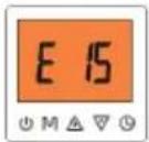
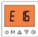
4.4.19.4.1 Diagnosis
The normal DC voltage between terminals P (DC+) and N (DC-) on inverter module PCB is 1.4 time of AC power supply in standby state. The DC voltage is 370V when the fan motor is running. If the voltage is lower than 180V, the unit displays E15 and shuts down. If the voltage is higher than 430V, the unit displays E16 and shuts down.
4.4.19.4.2 Possible causes
■ Power supply is abnormal.
■ Relay on the inverter module PCB is open.
■ Drive PCB is damaged.
Figure 4-19.4 Location of DC bus voltage terminals for 8/10/12kW:
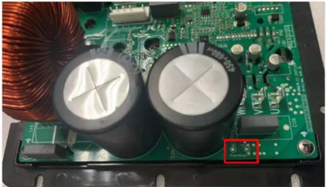
natural_image
Close-up of a green printed circuit board with copper inductors and capacitors, no visible text or symbols.Figure 4-19.5 Location of DC bus voltage terminals for 14/16kW:
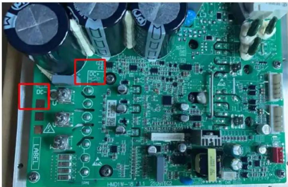
text_image
DC+ DC- LABEL HMD1W-18 1.1 210916024.4.19.4.2 Analysis and action

flowchart
graph TD
    A["E15 E16"] --> B["Power supply is abnormal?"]
    B -->|Yes| C["Re-start the unit once the power supply has returned to normal"]
    B -->|NO| D["Relay on the inverter module PCB is open?\( ^{1} \)"]
    D -->|Yes| E["Replace drive PCB"]
    D -->|NO| F["Replace drive PCB"]
Note:
- Refer to Figure4-2.2/2.3/2.4/2.5 for the location of the relays.
4.4.19.5 E17Diagnosis and analysis
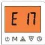
4.4.19.5.1 Diagnosis
E17 occurs when the instantaneous input current peak of the DC bus is over high.
4.4.19.5.2 Possible cause
The input power supply is abnormal, and the voltage suddenly decreases to cause the input current to increase.
■ Inductor on PFC module malfunctioned.
■ Inverter module PCB malfunctioned.
4.4.19.5.3 Analysis and action

flowchart
graph TD
    A["E17"] --> B["Power supply is abnormal?"]
    B -->|No| C["Inductor on PFC module malfunctioned?\( ^{1} \)"]
    B -->|Yes| D["Restart the unit once the power supply has returned to normal"]
    C -->|No| E["Replace drive PCB"]
    C -->|Yes| F["Replace the inductor"]
Note:
1. For 8/10/12/14/16kw, refer to Figure4-19.6 below for the location of the inductor.
Figure4-19.6
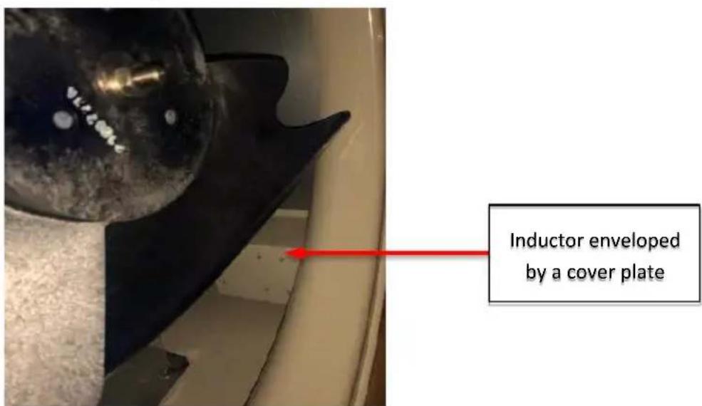
text_image
Inductor enveloped by a cover plate4.4.19.6 E18 E23 E29 E30 Diagnosis and analysis
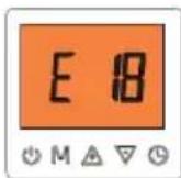

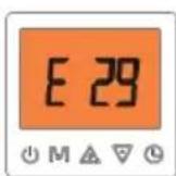
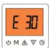
4.4.19.6.1 Diagnosis
■ Code E18 will occur when IPM module is abnormal.
■ Code E23 will occur when the instantaneous peak current of any phase of three phases the compressor U, V and W is over high.
■ Code E29 will occur when the internal circuit of IPM detecting temperature is abnormal.
■ Code E30 will occur when IPM module overheats.
4.4.19.6.2 Possible cause
■ The compressor phase sequence is incorrectly connected.
■ Too much refrigerant liquid flooded into the compressor.
■ The compressor malfunctioned.
■ Screws on the inverter module are loose.
■ The radiator on inverter module PCB has poor heat dissipation.
■ The inverter module PCB malfunctioned.
4.4.19.6.3 Analysis and action
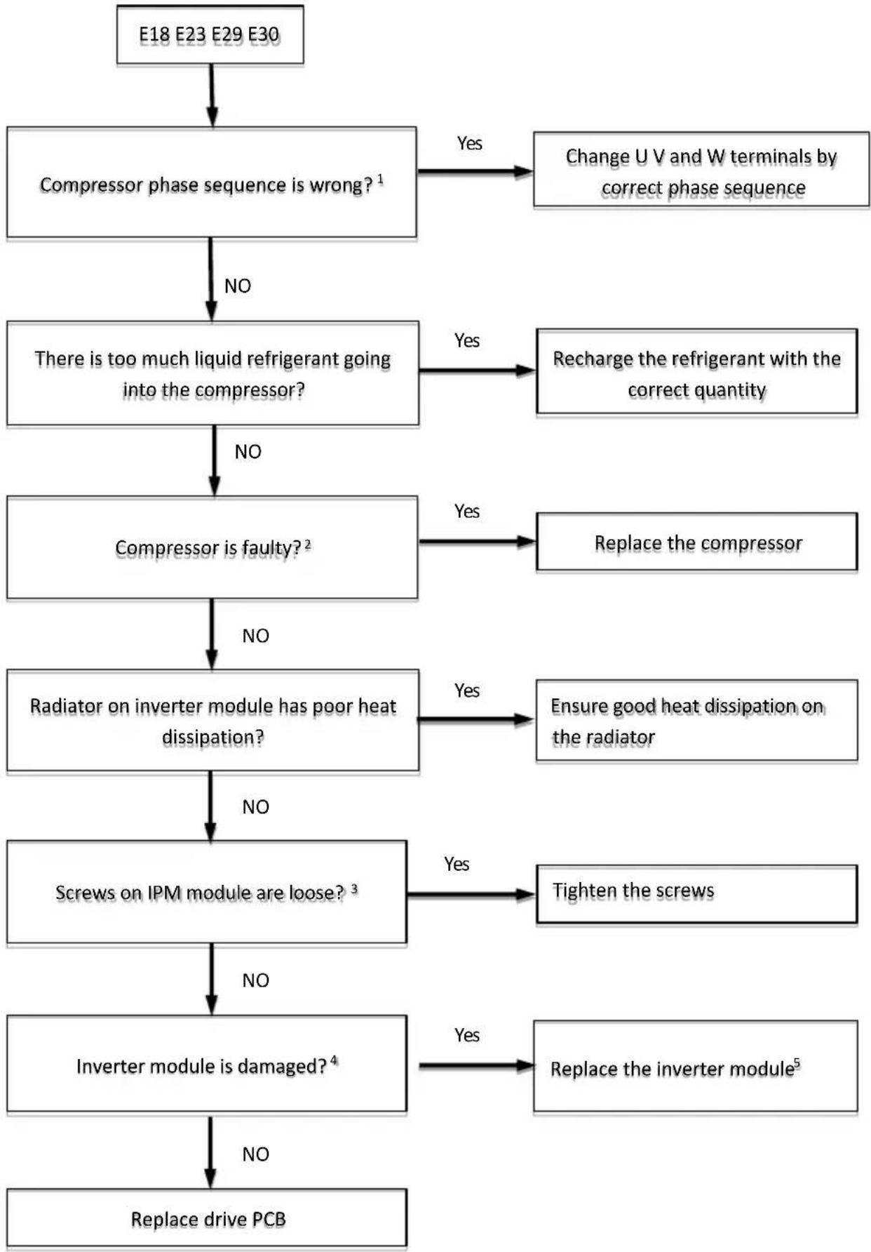
flowchart
graph TD
    A["E18 E23 E29 E30"] --> B["Compressor phase sequence is wrong?\( ^{1} \)"]
    B -->|No| C["There is too much liquid refrigerant going into the compressor?"]
    B -->|Yes| D["Change U V and W terminals by correct phase sequence"]
    C -->|NO| E["Compressor is faulty?\( ^{2} \)"]
    C -->|Yes| F["Recharge the refrigerant with the correct quantity"]
    E -->|NO| G["Radiator on inverter module has poor heat dissipation?"]
    E -->|Yes| H["Replace the compressor"]
    G -->|NO| I["Screws on IPM module are loose?\( ^{3} \)"]
    G -->|Yes| J["Ensure good heat dissipation on the radiator"]
    I -->|NO| K["Inverter module is damaged?\( ^{4} \)"]
    I -->|Yes| L["Tighten the screws"]
    K -->|NO| M["Replace drive PCB"]
    K -->|Yes| N["Replace the inverter module\( ^{5} \)"]
Note:
- Connect the U V W wire from the inverter module to the correct compressor terminals, as indicated by the labels on the compressor.
- The normal resistances of the inverter compressor are 0.35-1.5Ω among U V W and infinite between each of U V W and ground. If any of the resistances differ from these specifications, the compressor has malfunctioned.
- For 8/10/12kw, refer to Figure 4-19.8 for the layout of inverter module. For 14/16kw, refer to Figure 4-19.9 for the layout of inverter module.
- Measure the resistance between each of U, V and W and each of P and N on the inverter module. All the resistances should be infinite. If any of them are not infinite, the inverter module is damaged and should be replaced.
- When replacing an inverter module, a layer of thermally conductive silica gel should be painted on the IPM module, IGBT, diode bridge rectifier (on the reverse side of the inverter module PCB).
Figure 4-19.8 8/10/12kw
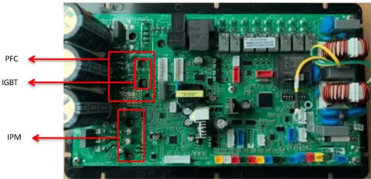
text_image
PFC IGBT IPMFigure 4-19.9 14/16kw
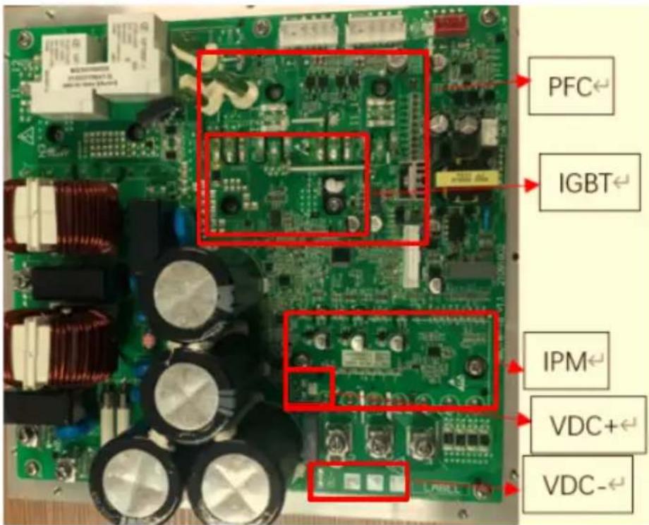
text_image
PFC← IGBT← IPM← VDC+← VDC-←4.4.20 E19 E24 E27Diagnosis and analysis
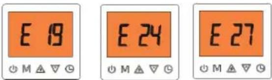
text_image
E 19 M △▽ ◎ E 24 M △▽ ◎ E 27 M △▽ ◎4.4.20.1 Diagnosis
■ E19 will occur when PFC module is abnormal.
■ E24 will occur when PFC module temperature is too high.
■ E27 will occur when the circuit of PFC module detecting temperature is abnormal.
4.4.20.2 Possible causes
■ The input power supply is abnormal.
■ Screws on PFC module are loose.
■ Internal PFC circuit detecting the temperature malfunctioned.
■ The radiator on PFC module has poor heat dissipation.
■ PFC module circuit malfunctioned.
■ Inverter module PCB is damaged.
4.4.20.3 Analysis and action
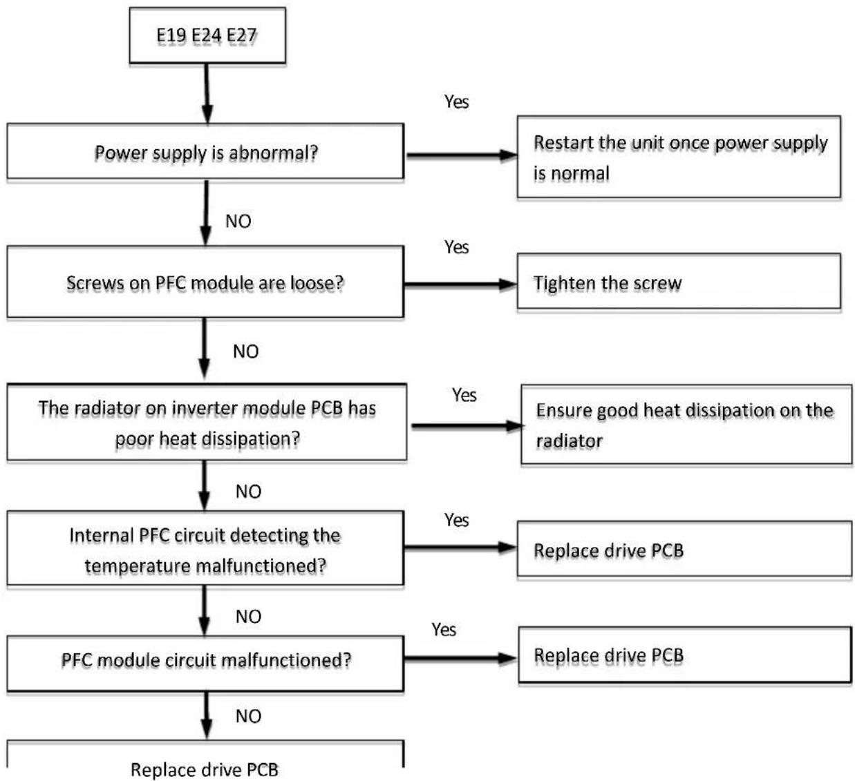
flowchart
graph TD
    A["E19 E24 E27"] --> B["Power supply is abnormal?"]
    B -->|No| C["Screws on PFC module are loose?"]
    B -->|Yes| D["Restart the unit once power supply is normal"]
    C -->|No| E["The radiator on inverter module PCB has poor heat dissipation?"]
    C -->|Yes| F["Tighten the screw"]
    E -->|No| G["Internal PFC circuit detecting the temperature malfunctioned?"]
    E -->|Yes| H["Ensure good heat dissipation on the radiator"]
    G -->|No| I["PFC module circuit malfunctioned?"]
    G -->|Yes| J["Replace drive PCB"]
    I -->|No| K["Replace drive PCB"]
    I -->|Yes| L["Replace drive PCB"]
    K --> M["Replace drive PCB"]
4.4.21 E20 E21Diagnosis and analysis
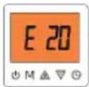
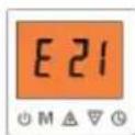
4.4.21.1 Diagnosis
Code E20 will occur when the compressor startup failed. When one or two phases are missing from the compressor phase line U V and W, Code E21 will occur.
4.4.21.2 Possible causes
■ Too much liquid flooded into the compressor.
There is too high pressure difference between inlet and outlet of the compressor.
■ There is a wrong compressor phase sequence.
4.4.21.3 Analysis and action
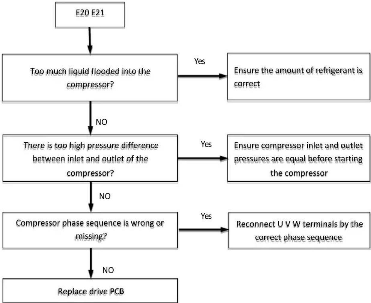
flowchart
graph TD
    A["E20 E21"] --> B["Too much liquid flooded into the compressor?"]
    B -->|No| C["There is too high pressure difference between inlet and outlet of the compressor?"]
    B -->|Yes| D["Ensure the amount of refrigerant is correct"]
    C -->|No| E["Compressor phase sequence is wrong or missing?"]
    C -->|Yes| F["Ensure compressor inlet and outlet pressures are equal before starting the compressor"]
    E -->|No| G["Replace drive PCB"]
    E -->|Yes| H["Reconnect U V W terminals by the correct phase sequence"]
    F -->|Yes| H
4.4.22 E25 Diagnosis, analysis and action
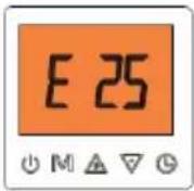
4.4.22.1 Diagnosis
Code E25 will occur when the circuit of detecting total input current of IPM module malfunctions.
4.4.22.2 Possible causes
Drive PCB is damaged.
4.4.22.3 Analysis and action
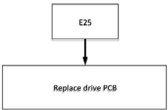
flowchart
graph TD
    A["E25"] --> B["Replace drive PCB"]
4.4.23 E26 Diagnosis, analysis and action
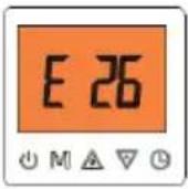
4.4.23.1 Diagnosis
Code E26 will occur when the actual running speed of the compressor deviated from the set speed, which is also called "out of step".
4.4.23.2 Possible causes
There are impurities in the compressor which may cause the frequency to be unstable.
■ Drive PCB is damaged
4.4.23.3 Analysis and action
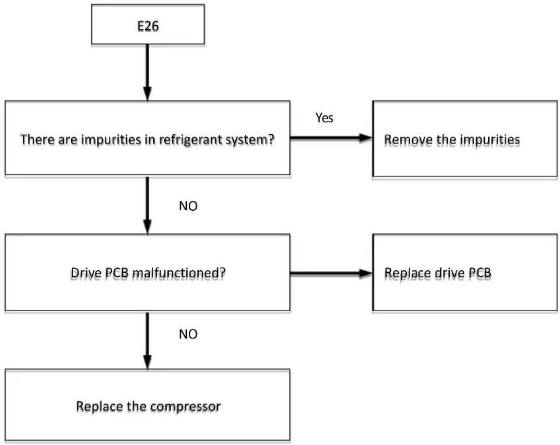
flowchart
graph TD
    A["E26"] --> B["There are impurities in refrigerant system?"]
    B -->|Yes| C["Remove the impurities"]
    B -->|NO| D["Drive PCB malfunctioned?"]
    D -->|No| E["Replace the compressor"]
    D -->|Yes| F["Replace drive PCB"]
4.4.24 E28Diagnosis, analysis and action
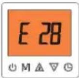
4.4.24.1 Diagnosis
Code E28 will occur when drive PCB receives no data or error data from refrigeration system. PCB in 30 seconds.
4.4.24.2 Possible causes
■ The communication cables with the main control PCB are loose or open.
■ Drive PCB is damaged.
4.4.24.3 Analysis and action
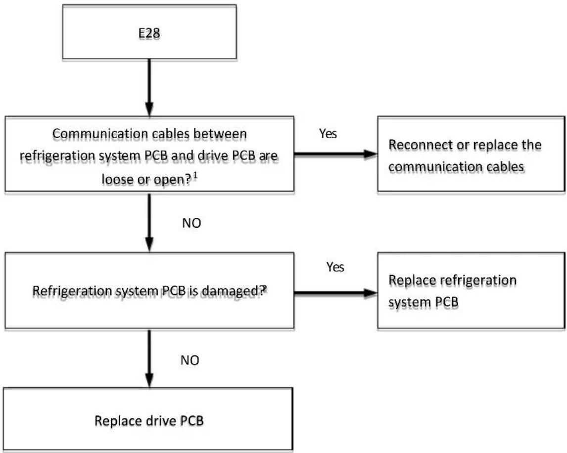
flowchart
graph TD
    A["E28"] --> B["Communication cables between refrigeration system PCB and drive PCB are loose or open?¹"]
    B -->|Yes| C["Reconnect or replace the communication cables"]
    B -->|NO| D["Refrigeration system PCB is damaged?²"]
    D -->|Yes| E["Replace refrigerator system PCB"]
    D -->|NO| F["Replace drive PCB"]
Note:
- Apply to 14/16kW models, for 8/10/12kW models no separator communication lines.
- Apply to 14/16kW models, for 8/10/12kW models no separator refrigeration system PCB.
4.4.25 E34 Diagnosis, analysis and action
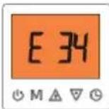
4.4.25.1 Diagnosis
Code E34 will occur when there is an abnormal main circuit voltage.
4.4.25.2 Possible causes
■ Actual power supply voltage is not within ±10% of rated voltage.
■ Heat pump is powered on immediately after power-off.
■ Loosened wiring within electric control box.
■ High voltage circuit error.
■ Drive PCB is damaged.
4.4.25.3 Analysis and action
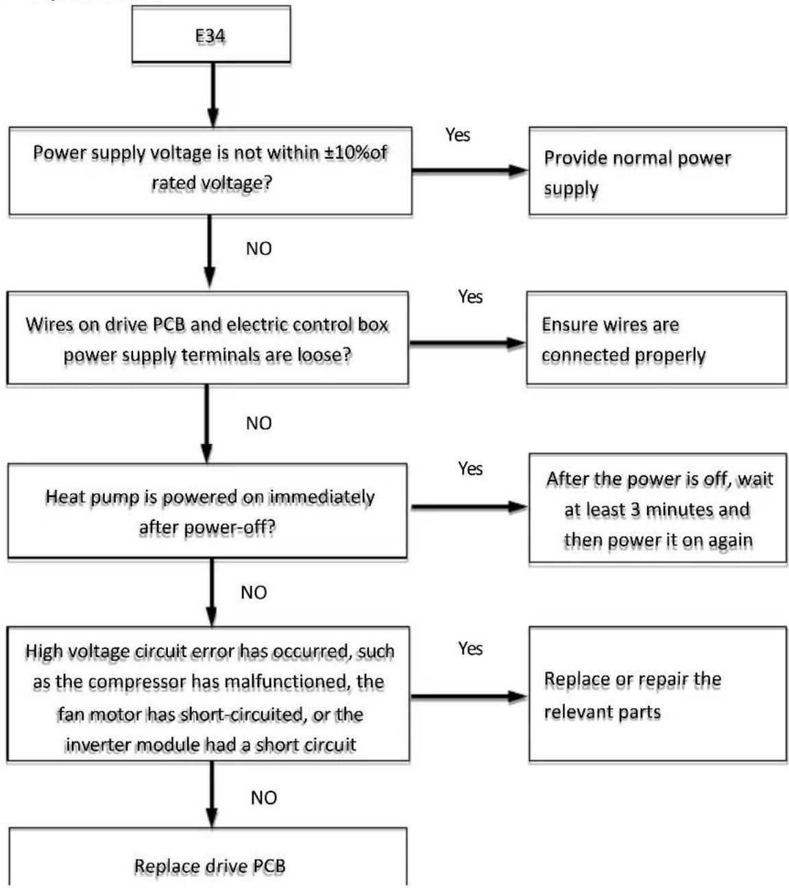
flowchart
graph TD
    A["E34"] --> B["Power supply voltage is not within ±10% of rated voltage?"]
    B -->|No| C["Wires on drive PCB and electric control box power supply terminals are loose?"]
    B -->|Yes| D["Provide normal power supply"]
    C -->|No| E["Heat pump is powered on immediately after power-off?"]
    C -->|Yes| F["Ensure wires are connected properly"]
    E -->|No| G["High voltage circuit error has occurred, such as the compressor has malfunctioned, the fan motor has short-circuited, or the inverter module had a short circuit"]
    E -->|Yes| H["After the power is off, wait at least 3 minutes and then power it on again"]
    G -->|No| I["Replace drive PCB"]
    G -->|Yes| J["Replace or repair the relevant parts"]
    I -->|No| K["Replace drive PCB"]
4.4.26 E22 E32 E33 E35 E37 E38 analysis

These codes mean the controller is performing some kind of specific action; they are neither error nor failure.
■ E22 will occur if the inverter module is resetting.
E32 E33 and E35 will occur if the inverter module is debugging the data.
E37 will occur if the compressor frequency is limited because of the input current of the inverter module.
E38 will occur if the compressor frequency is limited because of the input voltage of the inverter module.
4.4.27 E01/E02/E03/E04/E05/E06/E07/ E08/E09/E10/E14/E28 analysis
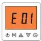
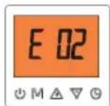
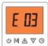
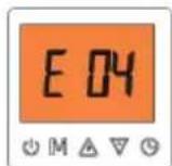
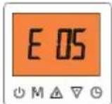
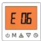
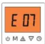
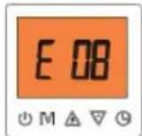
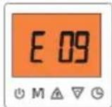

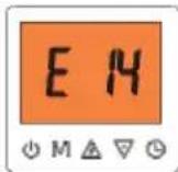
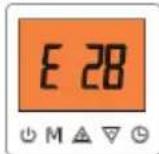
Before starting heat pump, if the communication cables with two cores (A and B) between the control board 1 and the control board 2 are not connected, all these errors above will occur on the user interface and don't start heat pump. First of all, you must confirm that the communication cables (A and B) between these two control boards have been connected correctly to start heat pump.
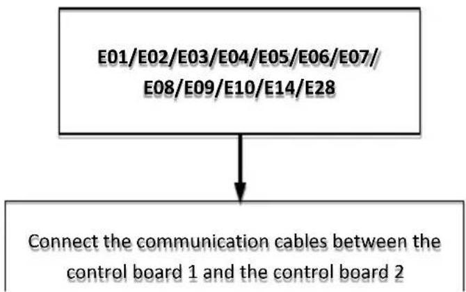
flowchart
graph TD
    A["E01/E02/E03/E04/E05/E06/E07/E08/E09/E10/E14/E28"] --> B["Connect the communication cables between the control board 1 and the control board 2"]
4.5 Appendixes to Part 4
4.5.1 Temperature Sensor Resistance Characteristics
Table 4-20.1: inlet water temperature sensor TA, outlet water temperature sensor TB, coil temperature sensor T3, outdoor ambient temperature sensor T4, liquid temperature sensor T5, and suction temperature sensor TH resistance characteristics
| Temp. (°C) | Resistance (kΩ) | Temp. (°C) | Resistance (kΩ) | Temp. (°C) | Resistance (kΩ) | Temp (°C) | Resistance (kΩ) |
| -20 | 106.732 | 20 | 12.635 | 60 | 2.350 | 100 | 0.609 |
| -19 | 100.552 | 21 | 12.050 | 61 | 2.264 | 101 | 0.591 |
| -18 | 94.769 | 22 | 11.496 | 62 | 2.181 | 102 | 0.574 |
| -17 | 89.353 | 23 | 10.971 | 63 | 2.102 | 103 | 0.558 |
| -16 | 84.278 | 24 | 10.473 | 64 | 2.026 | 104 | 0.542 |
| -15 | 79.521 | 25 | 10.000 | 65 | 1.953 | 105 | 0.527 |
| -14 | 75.059 | 26 | 9.551 | 66 | 1.883 | ||
| -13 | 70.873 | 27 | 9.125 | 67 | 1.816 | ||
| -12 | 66.943 | 28 | 8.721 | 68 | 1.752 | ||
| -11 | 63.252 | 29 | 8.337 | 69 | 1.690 | ||
| -10 | 59.784 | 30 | 7.972 | 70 | 1.631 | ||
| -9 | 56.524 | 31 | 7.625 | 71 | 1.574 | ||
| -8 | 53.458 | 32 | 7.296 | 72 | 1.519 | ||
| -7 | 50.575 | 33 | 6.982 | 73 | 1.466 | ||
| -6 | 47.862 | 34 | 6.684 | 74 | 1.416 | ||
| -5 | 45.308 | 35 | 6.401 | 75 | 1.367 | ||
| -4 | 42.903 | 36 | 6.131 | 76 | 1.321 | ||
| -3 | 40.638 | 37 | 5.874 | 77 | 1.276 | ||
| -2 | 38.504 | 38 | 5.630 | 78 | 1.233 | ||
| -1 | 36.492 | 39 | 5.397 | 79 | 1.191 | ||
| 0 | 34.596 | 40 | 5.175 | 80 | 1.151 | ||
| 1 | 32.807 | 41 | 4.964 | 81 | 1.113 | ||
| 2 | 31.120 | 42 | 4.763 | 82 | 1.076 | ||
| 3 | 29.528 | 43 | 4.571 | 83 | 1.041 | ||
| 4 | 28.026 | 44 | 4.387 | 84 | 1.007 | ||
| 5 | 26.608 | 45 | 4.213 | 85 | 0.974 | ||
| 6 | 25.268 | 46 | 4.046 | 86 | 0.942 | ||
| 7 | 24.003 | 47 | 3.887 | 87 | 0.912 | ||
| 8 | 22.808 | 48 | 3.735 | 88 | 0.883 | ||
| 9 | 21.678 | 49 | 3.590 | 89 | 0.855 | ||
| 10 | 20.610 | 50 | 3.451 | 90 | 0.828 | ||
| 11 | 19.601 | 51 | 3.318 | 91 | 0.802 | ||
| 12 | 18.646 | 52 | 3.191 | 92 | 0.777 | ||
| 13 | 17.743 | 53 | 3.069 | 93 | 0.753 | ||
| 14 | 16.888 | 54 | 2.952 | 94 | 0.730 | ||
| 15 | 16.079 | 55 | 2.841 | 95 | 0.708 | ||
| 16 | 15.313 | 56 | 2.734 | 96 | 0.686 |
| 17 | 14.588 | 57 | 2.632 | 97 | 0.666 |
| 18 | 13.902 | 58 | 2.534 | 98 | 0.646 |
| 19 | 13.251 | 59 | 2.440 | 99 | 0.627 |
Table 4-20.2: Domestic water tank temperature sensor TW and discharge pipe temperature sensor TP resistance characteristics
| Temp. (°C) | Resistance (kΩ) | Temp. (°C) | Resistance (kΩ) | Temp. (°C) | Resistance (kΩ) | Temp (°C) | Resistance (kΩ) |
| -30 | 952.951 | 9 | 116.582 | 48 | 21.633 | 87 | 5.503 |
| -29 | 896.036 | 10 | 111.120 | 49 | 20.817 | 88 | 5.329 |
| -28 | 843.054 | 11 | 105.942 | 50 | 20.036 | 89 | 5.162 |
| -27 | 793.682 | 12 | 101.031 | 51 | 19.288 | 90 | 5.000 |
| -26 | 747.627 | 13 | 96.372 | 52 | 18.571 | 91 | 4.844 |
| -25 | 704.627 | 14 | 91.952 | 53 | 17.885 | 92 | 4.694 |
| -24 | 664.442 | 15 | 87.758 | 54 | 17.227 | 93 | 4.549 |
| -23 | 626.856 | 16 | 83.776 | 55 | 16.597 | 94 | 4.409 |
| -22 | 591.673 | 17 | 79.996 | 56 | 15.993 | 95 | 4.274 |
| -21 | 558.714 | 18 | 76.406 | 57 | 15.414 | 96 | 4.144 |
| -20 | 527.817 | 19 | 72.996 | 58 | 14.859 | 97 | 4.018 |
| -19 | 498.833 | 20 | 69.756 | 59 | 14.326 | 98 | 3.896 |
| -18 | 471.626 | 21 | 66.677 | 60 | 13.815 | 99 | 3.779 |
| -17 | 446.072 | 22 | 63.750 | 61 | 13.324 | 100 | 3.666 |
| -16 | 422.057 | 23 | 60.967 | 62 | 12.854 | 101 | 3.557 |
| -15 | 399.475 | 24 | 58.321 | 63 | 12.401 | 102 | 3.451 |
| -14 | 378.231 | 25 | 55.803 | 64 | 11.967 | 103 | 3.349 |
| -13 | 358.235 | 26 | 53.408 | 65 | 11.550 | 104 | 3.251 |
| -12 | 339.406 | 27 | 51.129 | 66 | 11.150 | 105 | 3.156 |
| -11 | 321.666 | 28 | 48.959 | 67 | 10.765 | 106 | 3.064 |
| -10 | 304.948 | 29 | 46.893 | 68 | 10.395 | 107 | 2.975 |
| -9 | 289.185 | 30 | 44.926 | 69 | 10.039 | 108 | 2.889 |
| -8 | 274.317 | 31 | 43.051 | 70 | 9.697 | 109 | 2.806 |
| -7 | 260.288 | 32 | 41.265 | 71 | 9.368 | 110 | 2.726 |
| -6 | 247.047 | 33 | 39.563 | 72 | 9.052 | 111 | 2.649 |
| -5 | 234.545 | 34 | 37.941 | 73 | 8.748 | 112 | 2.574 |
| -4 | 222.737 | 35 | 36.393 | 74 | 8.455 | 113 | 2.502 |
| -3 | 211.581 | 36 | 34.918 | 75 | 8.173 | 114 | 2.433 |
| -2 | 201.038 | 37 | 33.510 | 76 | 7.902 | 115 | 2.365 |
| -1 | 191.071 | 38 | 32.166 | 77 | 7.641 | 116 | 2.299 |
| 0 | 181.647 | 39 | 30.884 | 78 | 7.389 | 117 | 2.237 |
| 1 | 172.733 | 40 | 29.659 | 79 | 7.147 | 118 | 2.176 |
| 2 | 164.300 | 41 | 28.490 | 80 | 6.914 | 119 | 2.115 |
| 3 | 156.319 | 42 | 27.373 | 81 | 6.689 | 120 | 2.058 |
| 4 | 148.765 | 43 | 26.306 | 82 | 6.473 | 121 | 2.002 |
| 5 | 141.613 | 44 | 25.286 | 83 | 6.264 | 122 | 1.949 |
| 6 | 134.839 | 45 | 24.311 | 84 | 6.063 | 123 | 1.897 |
| 7 | 128.423 | 46 | 23.378 | 85 | 5.869 | 124 | 1.846 |
| 8 | 122.343 | 47 | 22.487 | 86 | 5.683 | 125 | 1.797 |
| 126 | 1.750 | 130 | 1.575 | 134 | 1.421 | 138 | 1.283 |
| 127 | 1.704 | 131 | 1.535 | 135 | 1.385 | 139 | 1.251 |
| 128 | 1.660 | 132 | 1.496 | 136 | 1.350 | 140 | 1.220 |
| 129 | 1.617 | 133 | 1.458 | 137 | 1.316 | ||