
CS2500 - Uncategorized Texas - Free user manual and instructions
Find the device manual for free CS2500 Texas in PDF.


| Product Type | Fertilizer Spreader |
| Brand | Texas |
| Model | CS2500 |
| Power Source | Manual Push |
| Recommended Pushing Speed | 4.8 km/h (brisk walking pace) |
| Spreading Method | Impeller (rotating disc) |
| Included Accessories | Hopper screen, Rain cover |
| Wheels | 2 pneumatic wheels |
| Frame Material | Steel |
| Gearbox | Sealed with permanent lubrication |
| Assembly | Required (see manual) |
| Maintenance | Clean impeller and container after each use; do not open gearbox |
| Spare Parts Availability | Online at www.texas.dk |
| Adjustable Spreading Pattern | Yes (align gearbox front and adjust lever) |
| Warranty | Standard manufacturer's warranty |
Frequently Asked Questions - CS2500 Texas
User questions about CS2500 Texas
0 question about this device. Answer the ones you know or ask your own.
Ask a new question about this device
Download the instructions for your Uncategorized in PDF format for free! Find your manual CS2500 - Texas and take your electronic device back in hand. On this page are published all the documents necessary for the use of your device. CS2500 by Texas.
USER MANUAL CS2500 Texas
natural_image
Yellow and black manual push cart with wheels and bucket, no visible text or symbols on the vehicle itself.| A | B | C | D | E | F |
 |  |  | [∅x77] | 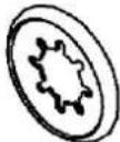 |  |
| AfstandsbøsHandle spaceAbstandsmembranУглубление длярукоятки x 1 | AkselbøsAxle bushingAchselhülseОсевая втулкax 2 | Skive ∅6Washer ∅6Scheibe ∅6Шайба ∅6 x 3 | Skrue M4x20Screw M4x20Schraube M4x20Винт M4x20 x 1 | EndekapselEnd capRadkappeЗаглушкаколеса x 2 | Møtrik M5Nut M5Mutter M5Гайка M5 x 1 |
| G | H | I | J | K | L |
 |  | [BXEN] | 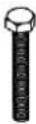 |  |  |
| Läsemøtrik M6Lock nut M6Kontermutter M6Стопорнаягайка M6x 11 | HärnålesplitPinNadelzackeШплинтx 1 | Skrue ∅6x40Screw ∅6x40Schrauben ∅6x40Винт ∅6x40x 4 | Bolt M6x45Bolt M6x45Bolzen M6x45Болт M6x45x 5 | Bolt M6x60Bolt M6x60Bolzen M6x60Болт M6x60x 2 | HändtagHandlesGriffРукояткиx 2 |
| M | N | O | P | Q | R |
 | 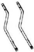 |  |  | 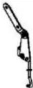 | 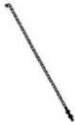 |
| RammeFrameRahmenРамax 1 | UnderstyrSubframeUntergestellОпорная рамax 2 | JusteringspladeLever assemblyDosierschaltungРычаг в сбореx 1 | StabiliseringsstangCross braceQuerstabilisatorСтабилизаторпоперечнойустойчивостих 1 | ForbindelsesstangPivot & bracketPleuelstangeШатунx 1 | KontrolstangControl rodSteuerstangeТяга управленияx 1 |
| S | T | U | V | W | X |
 | 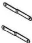 |  |  | 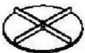 | 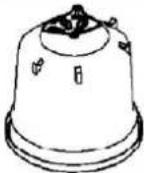 |
| HjulWheelRadKolecox 2 | RammebeslagFrame braceRahmenbeschlagУкосина рамыx 2 | GearGearboxGetriebeРедукторx 1 | StangHandle shaftPolВал рукояткиx 1 | ImpellerImpellerLaufradКрыльчаткax 1 | BeholderContainerBehälterЧашax 1 |
| Y | Z | AE | ∅ | Å | - |
 | [058c] | twerd |  |  |  |
| RistHopper screenGitterРешетчатаяпластинаx 1 | Bolt M6x35Bolt M6x35Bolzen M6x35Болт M6x35x 4 | Bolt M5x45Bolt M5x45Bolzen M5x45Болт M5x45x 1 | Skive ∅16Washer ∅16Scheibe ∅16Шайба ∅16x 1 | Nylon skiveNylon washerNylon scheibeНейлоноваяшайбax 4 | RegncoverRain coverAbdeckungЗащита от дождях 1 |
natural_image
Close-up of a black curved object with a small diamond-shaped indentation, partially visible against a blurred yellow background (no text or symbols)Fig. 1a
Fig. 1:
Monter rammen (M) på beholderen (X) med de medfølgende skruer (I) som vist Fig. 1a

Fig. 2a


natural_image
Close-up of a metal bracket with a bolt inserted, showing no visible text or symbolsnatural_image
Line drawing of a mechanical device with a spherical component mounted on a circular base (no text or symbols)Fig. 3

natural_image
Close-up of a mechanical component with yellow liquid and black handle (no visible text or symbols)Fig. 4a

natural_image
Close-up of a mechanical device with a circular component and a green handle (no visible text or symbols)
natural_image
Close-up of a black cylindrical object with metallic pins, possibly a mechanical or electronic component (no visible text or symbols)natural_image
Close-up of a black metal rod with a metallic clip attached, against a wooden background (no text or symbols visible)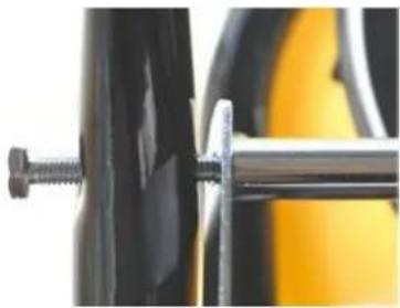
natural_image
Close-up of a mechanical clamp securing a black cylindrical component (no text or symbols visible)natural_image
Simple line drawing of a mechanical assembly with no text or symbolsFig. 6

natural_image
Close-up of a black mechanical component with a flange and cylindrical shaft, against a blurred green background (no text or symbols visible)Fig. 7a

Fig. 8a

Fig. 9a

natural_image
Close-up of a black mechanical component with a metallic fitting and a cylindrical shaft (no visible text or symbols)
natural_image
Close-up of a metallic electrical switch with a dial and metal frame (no visible text or symbols)Fig. 10

natural_image
Simple line drawing of a mechanical component with a hook and housing, enclosed in a circle (no text or symbols)Fig. 10a
Fig. 10:
Monter forbindelses-
stangen (Q) i pladen
under beholderen med
skiver (C) og møtrikker
(G) som vist i Fig. 10.

natural_image
Technical line drawing of a mechanical bracket assembly (no text or symbols)Fig. 11

natural_image
Close-up of a mechanical clamp or bracket with metal components and wires (no visible text or symbols)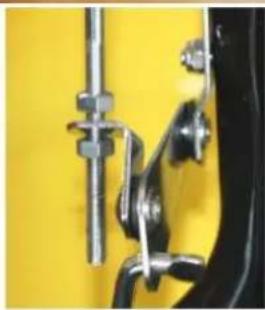
natural_image
Close-up of a mechanical clamp or bracket with metallic fittings against a yellow background (no text or symbols visible)natural_image
Technical line drawing of a mechanical clamp or bracket assembly (no text or symbols)Fig. 12
natural_image
Close-up of a metallic mechanical bracket with bolts and a metal rod (no visible text or symbols)Fig. 12a
Fig. 12:
Drej for at låse
kontrolstangen (Del R) i
justeringspladen (Del
O) som vist på Fig.12a

natural_image
Close-up of a metallic hook-like object with a central hole, held by black fingers against a yellow background (no text or symbols visible)Fig. 13

natural_image
Circular yellow filter or mesh structure with black dots at center (no text or symbols)natural_image
Technical line drawing of a mechanical linkage or bracket assembly (no text or symbols)Fig. 14
Fig. 14:
Trykket på
justeringshåndtaget kan
justeres på møtrikken
på siden af beslaget,
som vist på Fig.14
Spare parts
A spare part list for this device can be found at www.texas.dk. Specifying the respective spare part number will speed up delivery. Please contact your dealer if you wish to purchase spare parts. A list of dealers can also be found on our web site.
Useful information
If your spreader does not distribute the fertiliser evenly, ensure that the front of the gearbox is in line with the spreader. The impeller must rotate clockwise. If the gearbox is the wrong way round, the impeller will rotate anticlockwise.
Always clean the impeller after use. Dirt in the impeller will result in uneven spreading. The spreader is designed to be pushed at approx.4.8 km/h, which is the equivalent of brisk walking pace. Spreading at slower or faster speeds will alter the spreading pattern.
Caution! Wet spreading materials will alter the spreading pattern or block the opening of the container.
Clean your spreader thoroughly after every use. Wash the impeller and the base of the container. Do not open the gearbox! Permanent lubrication is put into the gearbox in the factory.
Assembly

Fig. 1

natural_image
Close-up of a black curved object with a small diamond-shaped indentation, partially held by yellow fingers (no text or symbols visible)Fig. 1a
Fig. 1:
Fit the frame (M) to the container (X) using the provided screws (I).
See Fig. 1a.

Fig. 2a


natural_image
Close-up of a metal bracket with a bolt inserted, showing no visible text or symbolsFig. 2b
Fig. 2: Fit the impeller (W) to the shaft of the gearbox (U) with the supplied screw (D) in the bottom hole. See Fig.2a and Fig. 2b.

natural_image
Line drawing of a mechanical device with a spherical component and lever (no text or symbols)Fig. 3
natural_image
Close-up of a mechanical component with yellow liquid and black handle (no visible text or symbols)Fig. 3a
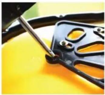
Fig. 3:
Install the gearbox (U) in the container (X) from the outside by inserting the shaft into the gearbox inside the container. See Fig.3a

Fig. 4a

natural_image
Close-up of a mechanical device with a circular component and a green handle (no visible text or symbols)
natural_image
Close-up of a black cylindrical object with metallic pins, possibly a mechanical or electronic component (no visible text or symbols)Fig. 4b
Fig. 4:
Place the subframe (N)
over the outer axle of
the gearbox (U), see
Fig. 4b
Insert the bolts (K) and nuts (G) into the bottom hole in the subframe (N) through the frame (M) on the right and left-hand sides. See Fig.4a
Please ensure that the frame fitting turns correctly.
Do not tighten the bolt nuts until both bolts have been installed.
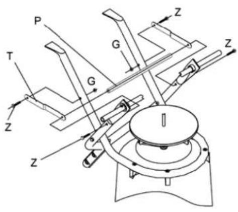
Fig. 5
natural_image
Close-up of a black metal rod with a metallic clip attached, against a wooden background (no text or symbols visible)
natural_image
Close-up of a mechanical clamp securing a black cylindrical component with yellow background (no text or symbols visible)Fig. 5a / Fig. 5b
Fig. 5:
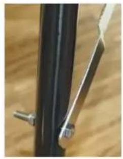
Fit the frame braces (T) into the top hole in the frame (M) in right and left side with bolts (Z) and nuts (G).
See Fig. 5a
Please ensure that the frame (T) fitting is turned correctly.
Fit the lateral stabiliser (P) into the bottom hole in the subframe (N) through the frame fitting (T). Use the bolt (J), see Fig. 5b.
natural_image
Simple line drawing of a mechanical assembly with no text or symbolsFig. 6
natural_image
Close-up of a black mechanical component with a flanged end, against a blurred green background (no text or symbols visible)Fig. 6a
Fig. 6:
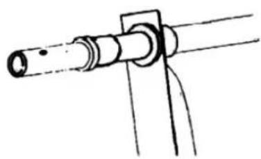
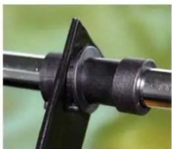
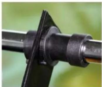
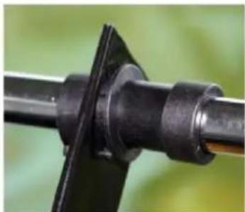
Fit the axle bushings (B) at both sides of the gearbox (U).
See Fig. 6a

Fig. 7a

Fig. 7b
Fig. 7:
Mount wheels with a nylon washer ( ) on each side of the wheel.
On the shaft with the hole, install a bolt ( ) and fix it with the nut (F).
On opposite shaft, a washer ( ) is added.
Fix the wheels on the outer side with the end caps (E).
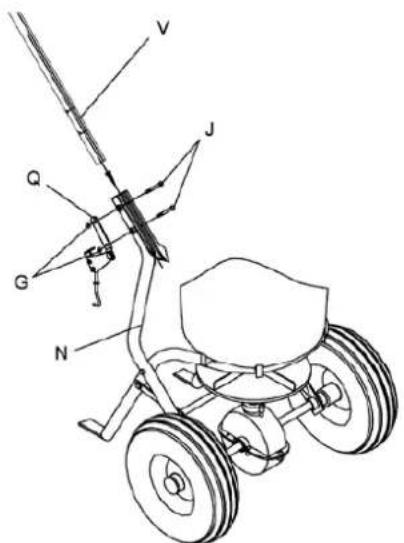
Fig. 8a
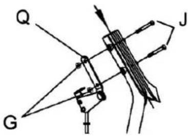
Fig. 8b
Fig. 8: Mount the handle shaft (V) between the subframes (N). Fig. 8a.
Place the pivot & bracket (Q) on the side of the subframe and tight it with the bolts (J) and the nuts (G). Fig. 8b
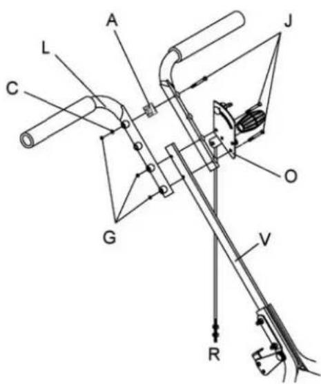
Fig. 9a

natural_image
Close-up of a black door with a metallic contact lens and a small white object on the left (no visible text or symbols)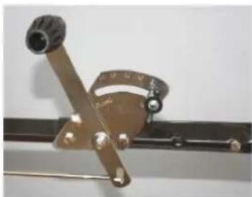
natural_image
Close-up of a metallic switch lever with a dial and knob (no visible text or symbols)Fig. 9b
Fig. 9:
Fit the handles (L) to the spacer bushes. Use the bolts (J). See Fig.9a
Fit the lever assembly (O) to the handle shaft (V), see Fig. 9b..
Please ensure that the dispenser lever is attached on the left side of the handle with the control lever on top.

Fig. 10

natural_image
Simple line drawing of a mechanical component inside a circular frame (no text or symbols)Fig. 10a
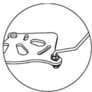
Fig. 10:
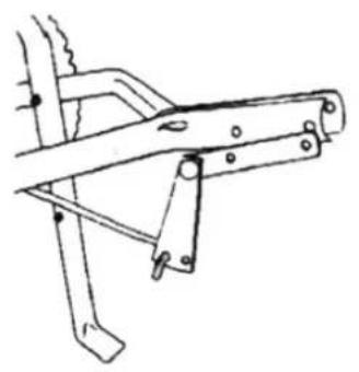
Attach the pivot & bracket (Q) on the plate beneath the container with washers (C) and nuts (G) as shown in Fig. 10.
natural_image
Technical line drawing of a mechanical bracket assembly (no text or symbols)Fig. 11

natural_image
Close-up of a mechanical clamp or bracket with metal components and a wire, no visible text or symbols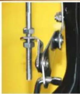
natural_image
Close-up of a mechanical clamp or bracket with metallic fittings against a yellow background (no text or symbols visible)Fig. 11a / Fig. 11b
Fig. 11:
Attach the other end of the connecting rod (Q) through the pole (V) on the left side of the handle with the slider at the bottom. Use bolts (J). See Fig. 11a.
Slide the dispenser lever (O) right to the top. Adjust the connecting rod (Q) and the control rod (R) so that the washer is being held beneath the container. Tighten the screw nut. See Fig.11b.

natural_image
Technical line drawing of a mechanical clamp or bracket assembly (no text or symbols)Fig. 12

natural_image
Close-up of a metallic mechanical bracket with bolts and a metal rod (no visible text or symbols)Fig. 12a
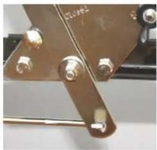
Fig. 12:
Screw the control rod (R) into the metering switch (O) to close it off.
See Fig 12a.

natural_image
Close-up of a metallic hook-like object with a central hole, held by black fingers against a yellow background (no text or symbols visible)Fig. 13

natural_image
Circular yellow filter or mesh structure with black dots at center (no text or symbols)Fig. 13a
Fig. 13:
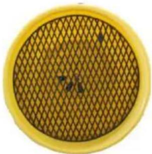
Fit the R-pin (H) to the axle on the inside of the container and place the hopper screen onto the container. See Fig. 13a.

natural_image
Technical line drawing of a mechanical clamp or bracket assembly (no text or symbols)Fig. 14
Fig. 14:
The dispenser lever can be adjusted at the fitting using the screw nut.
See Fig.14
Ersatzteile
natural_image
Close-up of a black curved object with a small diamond-shaped indentation and a small ring on top (no visible text or symbols)natural_image
Close-up of a metal bracket with a bolt inserted, showing no visible text or symbolsnatural_image
Line drawing of a mechanical device with a spherical component and lever (no text or symbols)Fig. 3

natural_image
Close-up of a mechanical component with yellow liquid and black handle, no visible text or symbolsFig. 4a

natural_image
Close-up of a mechanical device with a black circular component and green handle (no visible text or symbols)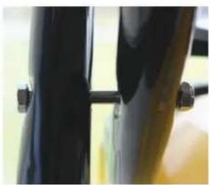
natural_image
Close-up of two black cylindrical objects with metallic fasteners, no visible text or symbolsnatural_image
Close-up of a black metal rod with a metallic clip attached, against a wooden background (no text or symbols visible)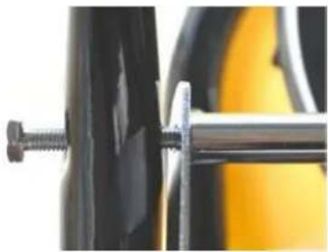
natural_image
Close-up of a mechanical clamp securing a black cylindrical component with yellow background (no text or symbols visible)natural_image
Simple line drawing of a mechanical assembly with no text or symbolsFig. 6
natural_image
Close-up of a black mechanical component with a flange and cylindrical shaft, set against a blurred green background (no text or symbols visible)Fig. 7a

Fig. 8a

Fig. 9a

natural_image
Close-up of a black door with a metallic contact and a small white object on the left (no visible text or symbols)
natural_image
Close-up of a metallic mechanical lever with a knob and handle (no visible text or symbols)Fig. 10
natural_image
Simple line drawing of a mechanical component inside a circular frame (no text or symbols)natural_image
Technical line drawing of a mechanical bracket or frame structure (no text or symbols)Fig. 11

natural_image
Close-up of a mechanical clamp or bracket with metal components and a screwdriver (no visible text or symbols)
natural_image
Close-up of mechanical clamps and bolts against a yellow background (no text or symbols visible)natural_image
Technical line drawing of a mechanical clamp or bracket assembly (no text or symbols)Fig. 12

natural_image
Close-up of a metallic mechanical bracket with four bolts and a metal rod (no visible text or symbols)natural_image
Close-up of a metallic tool with a central knob on a yellow surface, surrounded by black gloves (no text or symbols visible)Fig. 13

natural_image
Circular yellow filter or sieve with a mesh pattern and small dark spots, no text or symbols visible.natural_image
Technical line drawing of a mechanical joint or bracket assembly (no text or symbols)natural_image
Close-up of a black mechanical component with a small diamond-shaped hole, no visible text or symbolsРис. 1а
Рис. 1:
Присоедините раму
(M) к чаше (X) с
использованием
имеющихся винтов
(I). См. Рис. 1а.

Рис. 2а

natural_image
Close-up of a metallic tool interacting with a black metal bracket (no visible text or symbols)natural_image
Line drawing of a mechanical device with a central rotating component and a handle (no text or symbols)Рис. 3

natural_image
Close-up of a mechanical component with yellow liquid and black plastic housing (no visible text or symbols)Рис. 4а

natural_image
Close-up of a mechanical device with a circular component and lever (no visible text or symbols)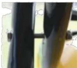
natural_image
Close-up of dark fabric or metal components with a metallic rod (no visible text or symbols)Рис. 5

natural_image
Close-up of a black cylindrical object with metallic pins and a small metallic clip, set against a wooden background (no text or symbols visible)
natural_image
Close-up of a mechanical assembly with a metallic bracket and black components (no visible text or symbols)natural_image
Simple line drawing of a mechanical assembly with no text or symbolsРис. 6
natural_image
Close-up of a black mechanical component with flange and bolt, against a blurred green background (no text or symbols visible)Рис. 6а
Рис. 6:
Рис. 7а

Рис. 7b
Рис. 7:
Рис. 8а

Рис. 9а

natural_image
Close-up of a black mechanical component with a metallic connector and textured surface (no visible text or symbols)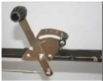
natural_image
Close-up of a metallic mechanical lever with a knob and mounting bracket (no visible text or symbols)Рис. 10

natural_image
Simple line drawing of a mechanical component inside a circular frame (no text or symbols)natural_image
Line drawing of a mechanical frame or bracket assembly (no text or symbols)Рис. 11

natural_image
Close-up of a mechanical clamp or bracket with metal parts and screws, no visible text or symbols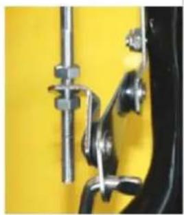
natural_image
Close-up of mechanical clamps and bolts against a yellow background (no text or symbols visible)natural_image
Technical line drawing of a mechanical clamp or bracket assembly (no text or symbols)Рис. 12

natural_image
Close-up of a metallic mechanical clamp or bracket with four bolts and a metal rod (no visible text or symbols)natural_image
Close-up of a metallic tool with a central hole on a yellow surface, held by black gloves (no text or symbols visible)Рис. 13
natural_image
Circular yellow filter or grid pattern with no visible text or symbolsnatural_image
Pure mechanical diagram showing a bracket and rod assembly without any text, numbers, or symbols| Ref# | Drawing No. | Description | Qty |
| 1 | N570-00012 | Handle Spacer | 1 |
| 2 | 9114-06025-DG | Carriage Bolt M6x25 | 1 |
| 3 | 9315-08000-DG | Teeth Washer ∅8 | 1 |
| 4 | N570-10000 | Gauge & Lever Assembly | 1 |
| 5 | N570-00001-DG | Adjust Handle Pole | 1 |
| 6 | N570-00014 | Adjust Handle A | 1 |
| 7 | N570-00015 | Adjust Handle B | 1 |
| 8 | 9118-04018-DG | Screw ∅4x18 | 1 |
| 9 | N510-00016 | Spacer | 1 |
| 10 | N510-00019 | Wing Nut | 1 |
| 11 | 9101-06045-DG | Hex Bolt M6x45 | 5 |
| 12 | C130-00004 | Nylon Washer | 1 |
| 13 | 9302-06000-DG | Big Flat Washer ∅6 | 1 |
| 14 | N570-00016 | Screen | 1 |
| 15 | N570-00009 | Handle Cover | 2 |
| 16 | N570-00013 | Hopper | 1 |
| 17 | N570-00017-DG | R Pin | 1 |
| 18 | N570-00019 | Hopper Bushing | 1 |
| 19 | N570-30000 | Pivot & Bracket Assembly | 1 |
| 20 | N570-00007 | Wheel Assembly Frame | 2 |
| 21 | 9201-06000-DG | Hex Nut M6 | 2 |
| 22 | T680-00003 | End Cover | 2 |
| 23 | N570-00006 | Upper Handle | 2 |
| 24 | 9206-06000-DG | Lock Nut M6 | 11 |
| 25 | N570-00003-DG | Control Rod A | 1 |
| 26 | N570-00005 | Handle Shaft | 1 |
| 27 | N570-00023 | Shut off plate | 1 |
| 28 | 9302-04000-DG | Big Flat Washer ∅4 | 3 |
| 29 | 9118-04012-DG | Screw M4x12 | 3 |
| 30 | N570-00008 | Frame | 1 |
| 31 | N570-00010-DG | Frame Brace | 2 |
| 32 | 9101-06060-DG | Hex Bolt M6X60 | 2 |
| 33 | 9102-06035-DG | Hex Bolt M6X35 | 4 |
| 34 | 9301-16000-DG | Flat Washer ∅16 | 1 |
| 35 | N511-40000 | End Cap | 2 |
| 36 | N570-00020 | Pneumatic Wheel | 2 |
| 37 | N570-00018 | Inner Axle Bushing | 2 |
| 38 | N570-00011 | Outer Axle Bushing | 2 |
| 39 | N570-40000 | Gear Box & Axle Assemble | 1 |
| 40 | N570-00002 | Thin Washer | 1 |
| 41 | 9110-04020-DG | Screw M4x20 | 1 |
| 42 | N510-00003 | Impeller | 1 |
| 43 | 9118-06040-DG | Screw ∅6x40 | 4 |
| 44 | 9206-05000-DG | Hex Lock Nut M5 | 1 |
| 45 | N570-00021-DG | Cross Brace | 1 |
| 46 | N570-00004-DG | Adjust Connect Rod B | 1 |
| 47 | 9101-05045-DG | Hex Bolt M5X45 | 1 |
| 48 | 9301-06000-DG | Flat Washer ∅6 | 4 |
| 49 | N570-00022 | Rain Cover | 1 |
| 50 | 9306-06000-DG | Lock Washer ∅6 | 1 |
| 51 | 9404-02010-DG | Cotter Pin ∅2x10 | 1 |
| 52 | N570-00027 | Nylon Washer | 4 |
EU-importør • EU-importer • Der EU-Importeur • Импортер EC
Texas Andreas Petersen A/S
Erklærer herved at materiel • Hereby certifies that the following • bescheinigt hiermit das die nachfolgenden • Настоящим заявляет, что следующий
Responsible person for documentation
Johnny Lolk
Johnny Lolk
Managing Director

TEXAS
Brand : Texas
Model : CS2500
Category : Uncategorized