
CL-W1 - Uncategorized Irritrol - Free user manual and instructions
Find the device manual for free CL-W1 Irritrol in PDF.


User questions about CL-W1 Irritrol
0 question about this device. Answer the ones you know or ask your own.
Ask a new question about this device
Download the instructions for your Uncategorized in PDF format for free! Find your manual CL-W1 - Irritrol and take your electronic device back in hand. On this page are published all the documents necessary for the use of your device. CL-W1 by Irritrol.
USER MANUAL CL-W1 Irritrol
Wireless Weather Sensor System User's Guide
Introduction
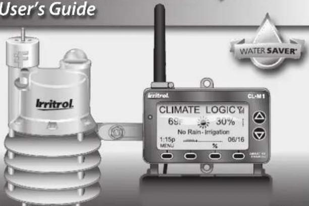
The Irritrol Climate Logic™ wireless weather sensor system transforms your automatic irrigation control system into a high-efficiency, water resource-management center.
Compatible with remote-ready Irritrol and Toro controllers, Climate Logic automatically regulates watering duration corresponding to real-time weather conditions and specific geographic and local weather profile information provided on a region-specific Setup Card. In addition, integral rain and freeze sensing further reduce wasteful, unnecessary irrigation and icing conditions.
Your Climate Logic system consists of a self-contained, Weather Sensor/Transmitter that continuously monitors current air temperature, solar radiation and precipitation. This data is transmitted at regular intervals throughout the day to the Receiver Module; linked directly to your controller's remote control port. Each day, Climate Logic calculates and adjusts the programmed station run time duration to the amount required for the next automatic watering cycle.
The Climate Logic system is designed for easy installation, setup and use. To take full advantage of the features and capabilities provided by the Climate Logic system, take a moment to review the detailed information provided within this guide.
To answer any questions you may have regarding the Climate Logic system, or any Irritrol product, please contact an Irritrol Customer Service representative at 1-800-634-8873.
text_image
User's Guide Irritrol CLIMATE LOGIC Ytl 6p 30% No Rain- Irrigation 1:15p 06/16 MENO %Quick Start Guide 2-3
System Components at a Glance 4–5
CL-M1 Receiver Module 4
CL-W1 Wireless Weather Sensor 5
Climate Logic System Installation 6-11
Receiver Module Installation and Setup......6-8
Weather Sensor Installation and Setup....9-11
Climate Logic System Operation....12–19
Control Feature Setup Options....12
Setup Menu Options 13
Utility Menu Options....14
Water Adjust Feature....15
Rain/Freeze Sensor Control Feature 16
Water History Review Feature......17
Weather Sensor Identification Feature....18
Control System Synchronization....19
Remote PIN Setup....19
Weather Sensor Battery Replacement....20
Specifications 21
FCC Information 22
Climate Logic System
Quick-Start Guide
The Quick-Start guide provides the essential steps required to properly install and setup the Climate Logic system in the most direct route possible. As needed, refer to the detailed information on the page number listed with each step.
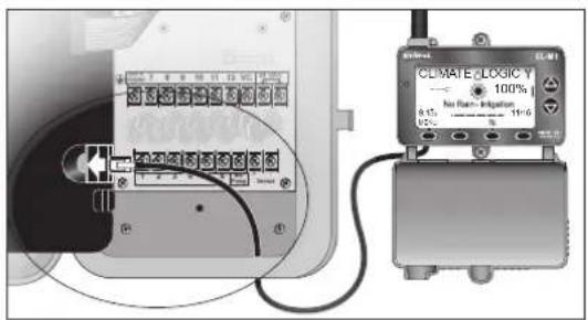
Step 1 – Connect and secure the Receiver Module next to the controller. See page 6.
Step 2 – Adjust controller program A for the hottest/driest conditions expected, without causing over-watering and runoff. Retain all watering time/day restrictions in the program schedule as required See page 6.
Step 3 – Synchronize the Receiver Module and controller to the current time and date. See page 7.
Step 4 – Insert the Receiver Module Setup Card as shown. See page 8.
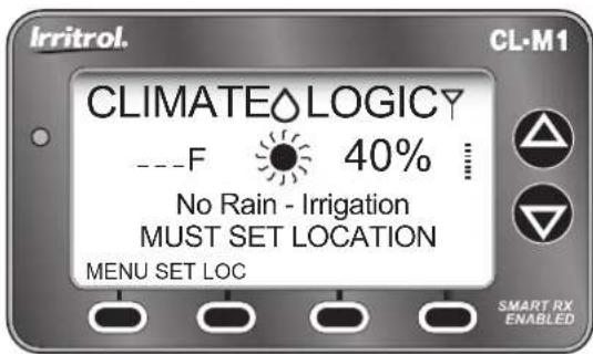
Step 5 – Establish your location by entering the five-digit ZIP code, or Lat/Lon coordinates as preferred. See page 8.
text_image
CLIMATE LOGIC Y 100% No Rated - Indication 11:00 0.15 0.25 CEM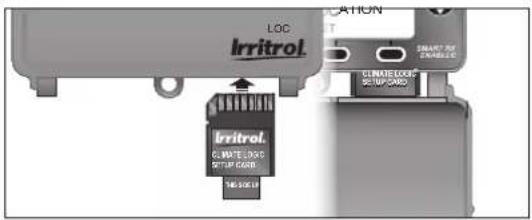
text_image
LOC Irritrol. SMART REF. CNT10000 Irritrol. SMART REF. CNT10000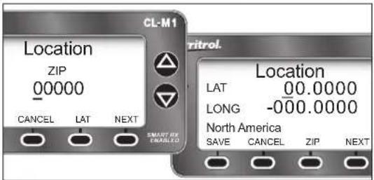
text_image
CL-M1 Location ZIP 00000 CANCEL LAT NEXT SMART EX EMERIALS ritrol. Location LAT 00.0000 LONG -000.0000 North America SAVE CANCEL ZIP NEXTQuick-Start Guide
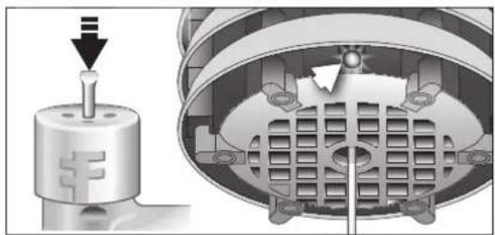
Step 6 – Press and hold the sensor Test Pin for 10–15 seconds to activate the Weather Sensor! A red LED (viewable through the lower vent ring) will illuminate twice after 10 seconds to confirm activation (if not already active). See page 9.
Step 7 – Press the sensor Test Pin again to confirm signal reception at the Receiver Module. The receiver's red LED will turn on momentarily when the signal is received. Press the BYPASS key to cancel the Dry-out mode delay period and resume normal operation. See page 9.
Note: If the LED does not turn on, refer to the Weather Sensor setup procedure on page 19.
Step 8 – Check the Rain Sensor threshold setting and adjust as needed. See page 10.
Step 9 – Secure the Weather Sensor to a rain gutter or other suitable structure that provides unrestricted exposure. Adjust the sensor alignment to vertical. See page 11.
natural_image
Mechanical assembly diagram showing a cylindrical component with a downward arrow and internal grid structure (no text or symbols)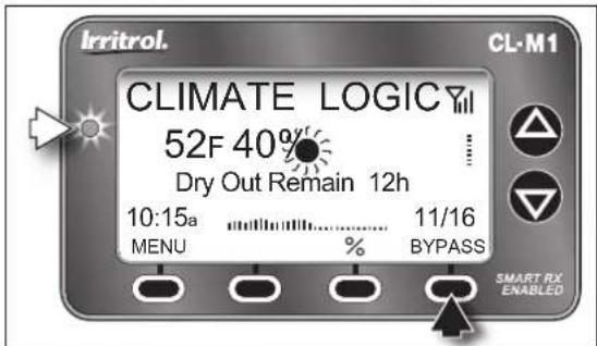
text_image
Irritrol. CLIMATE LOGICY 52F 40% Dry Out Remain 12h 10:15a MENU % 11/16 BYPASS SMART RX ENABLED CL-M1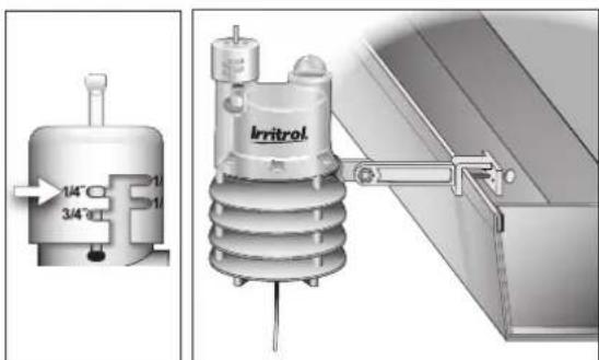
text_image
1/4°C 3/4°C IrritrolSystem Components at a Glance
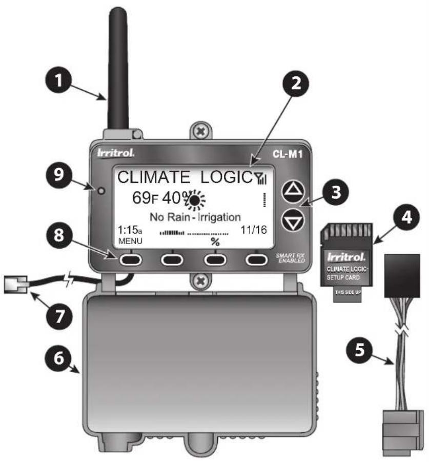
1 - Antenna
2 – LCD Screen: Large-format LCD screen provides enhanced clarity and use of text and graphics.
3 – Up/Down Arrow Keys: Control Menu cursor position, and adjust definable screen values.
4 – Setup Card: Provides historical weather data for regional location specified by ZIP code or Lat/Lon coordinates.
5 – CMR-ADP KwikDial Adaptor Cable: Adapts RJ25 connector to KwikDial controller's 5-pin receptacle.
6 – Cover: Provides weather-resistance and display protection in closed position.
7 – Connector Cable: Plugs into controller's remote control receptacle.
8 – Multifunction Keys: Key function is configured for each screen as required.
9 – LED Status Indicator: Remains On when irrigation is suspended; flashes when bypassed.
CL-M1 Receiver Module
text_image
1 2 Irritrol. CL-M1 9 CLIMATE LOGIC 69F 40% No Rain - Irrigation 1:15a 11/16 MENU % SMART RX ENABLED 3 8 7 6 4 Irritrol. CLIMATE LOGIC SETUP CARD THIS SIDE UP 5CL-W1 Wireless Weather Sensor
text_image
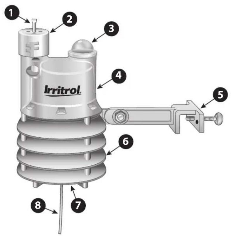
Irritrol. 1 2 3 4 5 6 7 81 - Weather Sensor Test Pin
Pressed to simulate rain sensor operation and test communication.
2 - Rain Sensor Adjustment Cap
Adjusts Rain Sensor threshold to a nominal setting of 1/8", 1/4", 1/2" or 3/4" (3 mm, 6 mm, 12 mm or 19 mm) of accumulated rainfall.
3 - Solar Collector
Collects and measures solar radiation. Requires full exposure to sunlight.
4 - Battery Compartment
Factory-installed 9V-Alkaline battery can sustain normal Weather Sensor operations up to five years.
5 - QuickClip™ Mounting Bracket
Convenient QuickClip mounting bracket provides quick and easy Weather Sensor installation.
6 - Temperature Sensor (not shown)
7 - RF Transmission LED (not shown)
8 - Antenna Wire
Climate Logic System Installation
Receiver Module Installation and Setup
Note: Installation methods must comply with all applicable national and local building codes.
- Setup controller watering Program A to provide an irrigation baseline for the Climate Logic system. The station run time, cycle start time(s), and watering day schedule* must be configured for the hottest/driest conditions expected, without causing over-watering and runoff. Retain all watering time/day restrictions in the program schedule as required.
Note: By default, Climate Logic modifies the run time of stations assigned only to Program A. To include Program B, or Programs B and C, see page 13.
*Note: For TMC-212 controller only: Interval day scheduling is not compatible with Climate Logic. Calendar and Odd/Even schedules are not affected.
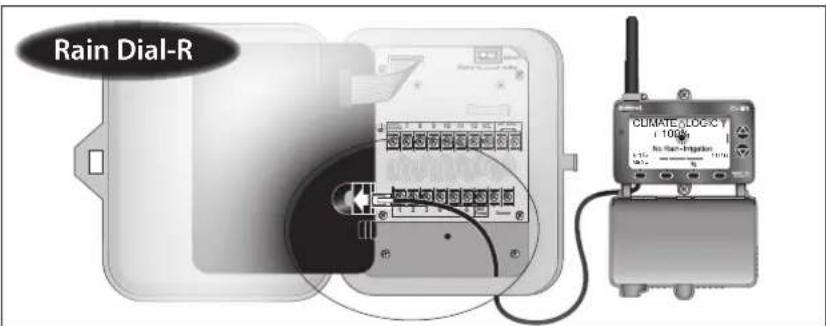
- Route the connection cable into the controller cabinet. Insert the cable connector into the controller's remote control jack.
Note: Use the provided CMR-ADP cable adapter assembly for KwikDial and MC-E (Blue) controller applications.
- Secure the Receiver Module to the wall next to the controller using the provided screws or other suitable fasteners.
Note: For indoor application, adhesive-backed hook and loop tape (not included) can be used instead of screws.
text_image
Rain Dial-R CLIMATE ADC/CT 100% No Rain-Integration 100%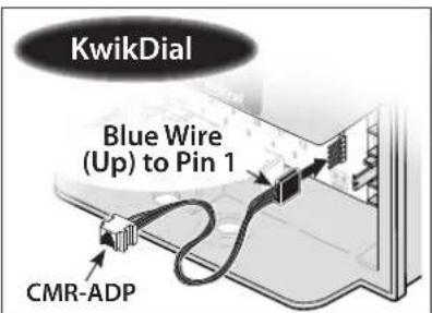
text_image
KwikDial Blue Wire (Up) to Pin 1 CMR-ADP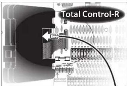
text_image
Total Control-R- The Receiver Module will automatically* synchronize time and date with the host controller upon initial power-up.
*Note: Does not apply to TMC-212 controller.
- Verify that the time and date are synchronized correctly. If necessary, adjust the Receiver Module as follows:
Note: The display will automatically return to the Home screen if a key is not pressed within 60 seconds.
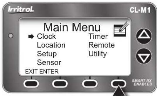
- Press the MENU key to display the Main Menu screen. (The CLOCK menu option is selected by default.)
- Press the ENTER key to display the Clock review screen.
- Press the SETUP key to display the Set Clock screen.
Note: To download the current time and date from the controller, press the GET key. When prompted, press the YES key.
- Press the ▲ or▼ to adjust the selected (underscored) value. Press the NExT key to select the next value. Continue setting the current day, year and time.
Note: To change the clock time display format, press the 12/24 key. To return to the previous screen without making changes, press the CANCEL key. - When the Receiver Module and controller are synchronized to the current time and date, press the SAVE key.
- Press the ExIT key two times to return to the Home screen.
text_image
Irritrol. Main Menu Clock Location Setup Sensor EXIT ENTER Timer Remote Utility SMART RX ENABLED CL-M1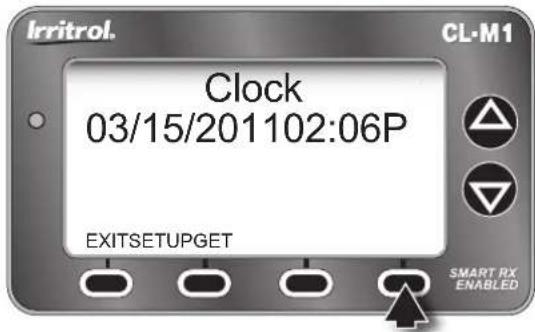
text_image
Irritrol. Clock 03/15/201102:06P EXITSETUPGET SMART RX ENABLED CL-M1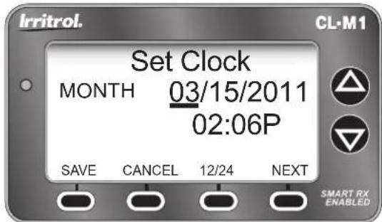
text_image
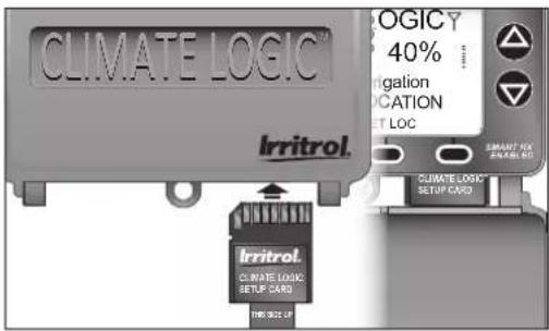
Irritrol. Set Clock MONTH 03/15/2011 02:06P SAVE CANCEL 12/24 NEXT SMART RX ENABLED- With the cover closed, insert the Climate Logic Setup Card into the Receiver Module slot as shown. Open the cover to proceed.
Note: The Home screen (right) will be displayed
text_image
CLIMATE LOGIC IRITROL. IRITROL. CLIMATE LOGIC SETUP CARD THE 902.1F LOGICY 40% rigation LOCATION NET LOC SMART MAX SINEMA PROC CLIMATE LOGIC SETUP CARDonly when a location has not been established, or has been erased. Press the SET LOC key to display the Location screen.
- Establish the site location as follows:
- PresMENU ⇒ LOCATION ⇒ ENTER to display the Location screen.
Note: The Lat/Lon Location screen will be displayed by default. To set the location using a 5-digit ZIP code, press the ZIP key.
- Press the △ or key to adjust the selected value. Press the NExT key to select the next value in sequence.
- When the location information is displayed correctly, press the SAVE key.
Note: The Receiver Module will begin transferring specific data from Setup Card for the defined location. A confirmation screen will indicate the completed transfer.
- Press the Exit key (two times) to return to the Home screen.
- Remove the Setup Card and stow inside the controller cabinet.
text_image
Irritrol. CL-M1 CLIMATELOGICY ---F 40% No Rain - Irrigation MUST SET LOCATION MENU SET LOC SMART RX ENABLED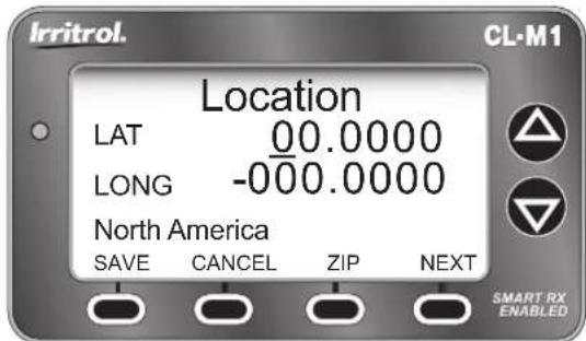
text_image
Irritrol. Location LAT 00.0000 LONG -000.0000 North America SAVE CANCEL ZIP NEXT SMART RX ENABLED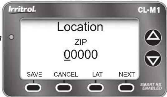
text_image
Irritrol. CL-M1 Location ZIP 00000 SAVE CANCEL LAT NEXT SMART RX ENABLEDWeather Sensor Installation and Setup
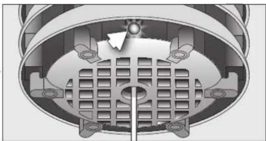
⚠️ Important: The Climate Logic Weather Sensor is shipped with the battery circuit deactivated. To initially activate the sensor prior to installation, press and hold the Test Pin for 10–15 seconds. A red LED, viewable from the lower vent area, will illuminate twice after 10 seconds (if not already active).
Note: The Weather Sensor and Receiver Module are paired for wireless communication from the factory. The following procedure will only be required if Please Add Sensor is displayed on the Home screen.
-
Pair the Weather Sensor transmitter with the Receiver Module to establish wireless communications as follows:
-
From the Home screen, press the ADD-SEN key to display the Sensor Setup screen. Press the ADD key to initiate the sensor ID search function.
- Press and release the Test Pin to "Ping" the Receiver Module. When pairing is successful, the 7-digit sensor ID is displayed.
natural_image
Cross-sectional diagram of a mechanical or electrical component with no visible text or symbols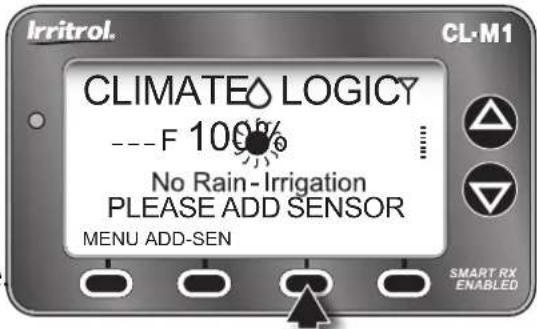
text_image
Irritrol. CL-M1 CLIMATE LOGICY ---F 100% No Rain-Irrigation PLEASE ADD SENSOR MENU ADD-SEN SMART RX ENABLED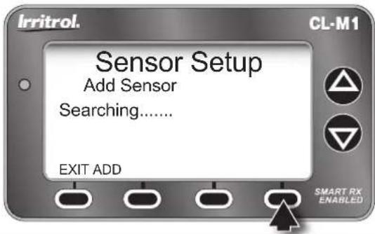
text_image
Irritrol. Sensor Setup Add Sensor Searching...... EXIT ADD SMART RX ENABLED CL-M1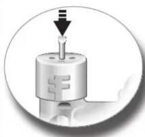
natural_image
Close-up of a mechanical component with a downward arrow and a central shaft, no visible text or symbols.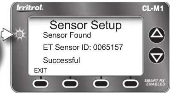
text_image
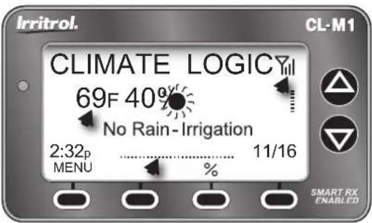
Irritrol. Sensor Setup Sensor Found ET Sensor ID: 0065157 Successful EXIT SMART RX ENABLED CL-M1- Press the ExIT key (three times) to return to the Home screen. After a brief time, the current temperature, watering history graph line, and signal-strength bars will be displayed.
Note: A single Weather Sensor can be paired to multiple Receiver Modules when additional Climate Logic systems are installed within reception range.
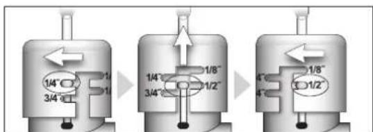
- The Rain Sensor default threshold is 14 " (6 mm) of accumulated rainfall (nominal). The threshold can be lowered to 18 " (3 mm) or raised to 12 " (12 mm), or 34 " (19 mm) as preferred. Prior to installing the Weather Sensor, adjust the threshold to the preferred set
text_image
Irritrol. CL-M1 CLIMATE LOGICY 69F 40° No Rain-Irrigation 2:32p MENU 11/16 % SMART RX ENABLEDNote: Increasing the threshold extends the length of time required for the Weather Sensor to signal the Receiver Module to stop irrigation, as well as extending the dry-out period before scheduled watering can resume. In areas where heavy fog, mist or high humidity is common, the 18 " (3 mm) setting is not recommended due to the increased sensitivity to moisture.
- Turn the Rain Sensor cap slightly, releasing it from the retention pins, allowing the cap to move vertically.
- Turn the cap to engage the retention pins at the preferred slot position.
text_image
1/4" 3/4" 1/8" 1/2" 1/8" 3/4" 1/2"⚠️ Important: The Weather Sensor must have full exposure to sun, wind and rain, and must not be installed inside a rain gutter, or in any location where immersion, runoff, or contact with irrigation spray will occur. Avoid installation near a heat source, such as a heater vent or chimney. Wooden surfaces are preferred to concrete or asphalt shingles to reduce reflected heat. Installation over a planted area is preferred to a driveway, walkway etc. Avoid installation near any large metal structure, or high current-draw equipment that can cause signal interference. Ensure the antenna wire hangs vertically without contact.
-
The Climate Logic system is designed to provide effective wireless communication in most applications. Loss of range can result from interference in the signal path. To verify signal reception from the selected installation site, perform the following test:
-
Start a manual watering operation of a zone that can be seen from the installation site. Press and hold the Sensor Test Pin. If the signal is received, watering should shut off within a short time.
- Note the signal bars on the Home screen to verify good signal strength. Three bars is optimal.
-
Press the BYPASS key to cancel the Dry-out delay mode to resume normal operation.
-
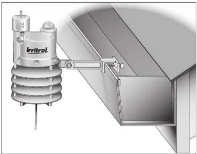
Install the Weather Sensor using either of the following methods:
-
For rain gutter installation, unscrew the bracket thumbscrew enough to clear the rain gutter edge. Holding the Weather Sensor in position, tighten the thumbscrew securely.
- For wood structure installation, remove the thumbscrew and secure the bracket using the provided screws or appropriate stainless fasteners.
- Adjust the vertical alignment as needed by loosening the phillips screw at the bracket joint; adjust to vertical, then tighten securely.
natural_image
Technical illustration of an Irritrol electrical insulator mounted on a structural panel (no text or symbols visible)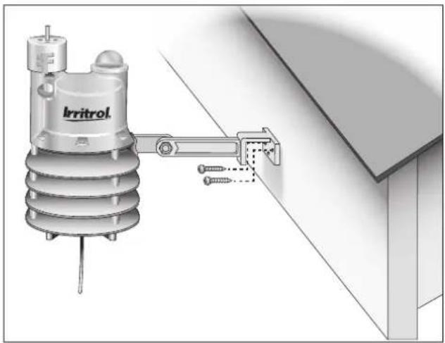
natural_image
Illustration of an Irritrol electrical insulator mounted on a wall, showing mounting hardware and wiring (no text or symbols)Climate Logic System Operation
Control Feature Setup Options
The Climate Logic system control features, accessible through the Setup and Utility menu screens, determine how and when the system displays information and performs various functions that regulate weather-defined automatic irrigation. The control feature-set, listed below in menu order, includes the factory default setting and the setup parameter for each.
| Setup Menu Features Default Setup Parameter | ||
| Auto Program Adjust Program A Program A, A & B or A, B & C | ||
| Water Restriction Start Time None Any hour | ||
| Water Restriction Duration None 0–24 hours (in 1⁄2-hour increments) | ||
| Schedule Update Time 8:00 p.m. Any hour | ||
| Average Percent Days 3 1–7 Days | ||
| Freeze Temperature 39° F (4°C) 35°–45°F (in 2° increments) | ||
| Dry-out days | 0.5 | 0–3 days (in 1⁄2-day increments). |
| Utility Menu Features | Default Setup Parmater | |
| Contrast | Balanced | Increase/Decrese (incremental) |
| Units (of measure/time format) | English, 12H | Metric, 24H |
Note: History, Default, Loader, and About utility menu items are provided for reference and service use only, and do not provide user-defined setup options. Refer to page 17 for detailed History feature information.
Setup Menu Options
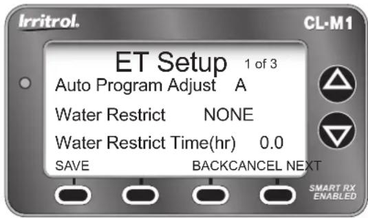
The following Setup features are accessed through the ET Setup menu (MENU SETUP ENTER).
All setup parameters are selected, adjusted and entered using the NExT/BACK, ▲no SAVE keys.
Auto Program Adjust: In all cases, Climate Logic regulates the run time of all stations assigned to Program A. The Auto Program Adjust feature enables stations assigned to Program B, or Programs B and C to be regulated as well.
Watering Restriction Setup: This feature enables the Climate Logic system to restrict watering for a specified daily time period. The restriction-period start time can be set to any hour of the day. The duration period can be set from 0 to 24 hours, in 30-minute increments.
Schedule Update Time: The Weather Sensor transmits weather-related data to the Receiver Module at regular intervals throughout the day. At the default time of 8:00 p.m., the watering adjustment
text_image
Irritrol. CL-M1 ET Setup 1 of 3 Auto Program Adjust A Water Restrict NONE Water Restrict Time(hr) 0.0 SAVE BACKCANCEL NEXT SMART RX ENABLED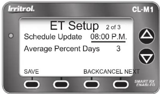
text_image
Irritrol. CL-M1 ET Setup 2 of 3 Schedule Update 08:00 P.M. Average Percent Days 3 SAVE BACKCANCEL NEXT SMART RX ENABLEDfactor for the next 24 hours is calculated and updated on the Home screen. The Schedule Update Time can be set to any hour of the day, but is recommended to occur between scheduled watering operations.
Average Percent Days: This setting defines how many days of compiled weather data are used to calculate the current watering adjustment % factor. By default, Climate Logic compiles data from the three previous days to provide a moderately smooth adjustment factor. This feature can be adjusted from 1 to 7 days. Decreasing the number of days, increases the adjustment variation; increasing the number of days results in less variation and a smoother daily average.
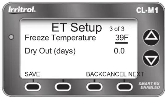
Freeze Temperature (threshold): The freeze sensor activation threshold can be adjusted from 39 °F, (default) down to 35 °F, or increased to 45 °F, in 2° increments.
⚠️ Important: Freeze sensor operation should be used only when the watered area can be visually monitored. While the Freeze Sensor is designed to cancel watering when air temperature is near freezing, automatic watering can occur in certain circumstances. For example, the air temperature may rise slightly above the sensor threshold, while the temperature of the adjacent walkways remains below freezing.
text_image
Irritrol. CL-M1 ET Setup 3 of 3 Freeze Temperature 39F Dry Out (days) 0.0 SAVE BACKCANCEL NEXT SMART RX ENABLEDWatering in this condition can result in unsafe walkway conditions. The Freeze Sensor feature is not intended to replace any winterization procedures normally used to prevent freeze-related irrigation system damage.
Dry-out Days: This setting determines the minimum length of time that must elapse after the release of a rain/freeze hold, and automatic watering can resume. By default, the dry-out period is 12 day (12 hours), and is adjustable from 0 to 3 days in 12 -day increments.
Utility Menu Options
The following Utility features are accessed through the Utility Menu screen (MENU UTILITY ENTER).
Display Contrast (CONTRAST ENTER): The LCD screen contrast is factory set at the midpoint adjustment range. Contrast intensity can be adjusted incrementally to the preferred level.
Units: (UNITS ENTER): By default, all units of measure are displayed in English standard format, and time in 12-hour (a.m./p.m.) format. Metric units of measure, and/or 24-hour (military time) formats can be selected as preferred.

text_image
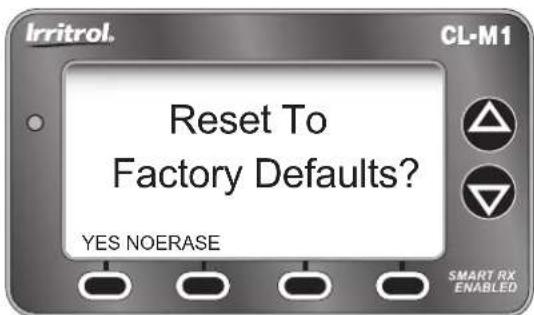
Irritrol. Utility Menu ► Contrast Loader Units About History Default EXIT ENTER SMART RX ENABLED CL-M1Default (DEFAULT ENTER): The Default utility feature enables all user-defined setup parameters to be either erased and reset to the factory default settings, or a complete system reset including Location, History, and Sensor Pairing.*
- Press the YES key to reset to the Factory Default settings. See Default settings listed on page 12.
- Press the NO key to return to the previous screen.
-
Press the ERASE key to display the Erase All prompt screen.
-
Press the NO key to return to the Utility Menu screen.
- Press the FACTORY key to return the Factory Reset screen.
- *Press the YES key to initiate the complete system reset.
Complete the procedure as indicated on the prompt screens.
Water Adjust Feature
The Water Adjust feature enables watering time to be fine-tuned by applying small adjustments universally to all weather-regulated stations.
From the Home screen, press the 🔊key to access the Water Adjust screen and to adjust scale. Press the SAVE key to enter the change and return to the Home screen.
Note: If a particular watering zone appears over-or under-watered, adjust the station run time in the controller watering program. It is considered best practice to make adjustments in small increments; allowing several days between changes to observe the results.
text_image
Irritrol. Reset To Factory Defaults? YES NOERASE SMART RX ENABLED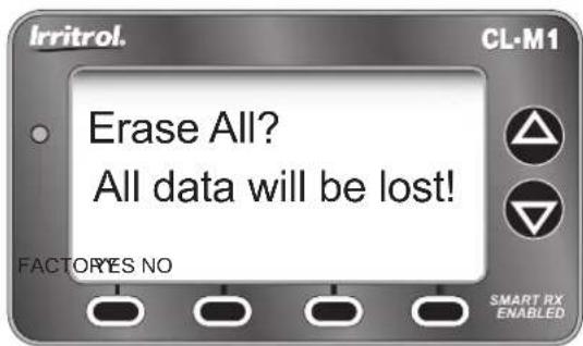
text_image
Irritrol. CL-M1 Erase All? All data will be lost! FACTORYS NO SMART RX ENABLED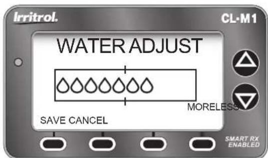
text_image
Irritrol. CL-M1 WATER ADJUST SAVE CANCEL MORELESS SMART RX ENABLEDRain/Freeze Sensor Control Feature
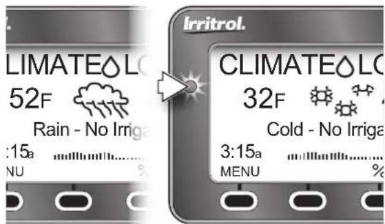
When rain or a low temperature condition is detected, system operation is placed on hold. The Sun icon is replaced with the corresponding Rain Cloud or Snow Flakes icon. The LED status indicator is on continuously while the system is on Hold.
When weather conditions improve, the Climate Logic system automatically resets for normal operation. An adjustable Dry-out period will prevent automatic watering for 12 hours (by default) before scheduled watering can resume. The Dry-out mode is adjustable from 0 to 3 days, in 12 -day increments. To adjust the Dry-out time period, refer to the Dry-out Days setup procedure on page 14.
Note: To resume watering operation immediately after the reset, press the BYPASS key to skip the Dry-out mode.
Smart Bypass Mode: While the system is on hold, sensor control can be toggled Off and On by pressing the BYPASS key. The Bypass mode will be indicated on the Home screen, and the LED indicator will blink continuously. Watering operations can resume, however the Climate Logic system will remain in the Bypass mode until the system automatically resets after the Dry-out duration times out.
Note: To resume sensor control mode, press the BYPASS key again to toggle the Bypass mode Off.
text_image
LIMATELO 52F Rain - No Irrig :15a NU Irritrol. CLIMATELO 32F Cold - No Irriga 3:15a MENU %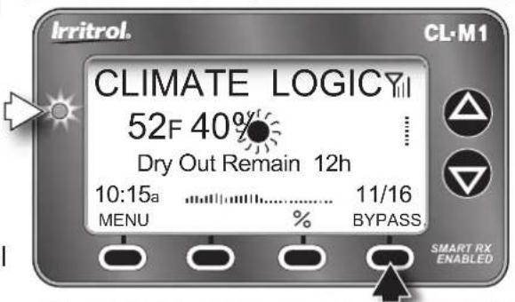
text_image
Irritrol. CL-M1 CLIMATE LOGICY 52F 40% Dry Out Remain 12h 10:15a 11/16 MENU % BYPASS. SMART RX ENABLED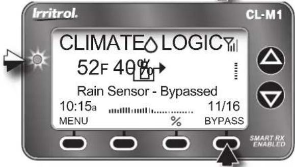
text_image
Irritrol. CL-M1 CLIMATE LOGICY 52F 40% Rain Sensor - Bypassed 10:15a 11/16 MENU % BYPASS SMART RX ENABLEDWater History Review Feature
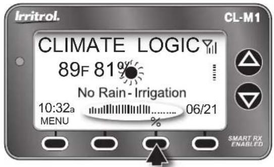
The Climate Logic system tracks and records the daily adjustment factor for a rolling, two-year period. A one-month snapshot is represented by the small bar graph on the Home screen. The graph is updated daily, and builds from the left to right, with the most recent day appearing on the left of the scale.
Pressing the \% key displays the Water History graph in a large-scale format. By default, the graph represents the daily adjustment history for a one-month period. Pressing the ZOOM key displays the history data in time frames of approximately 2-months, 6-months, 1-year, and 2-years.
Watering history data can also be reviewed in a contextual format, accessible through the History option of the Utility Menu. (MENU UTILITY HISTORY).
The History screen lists the date and adjustment % value for each day in chronological order, with the most recent entry at the bottom. Use the NExT and BACK keys to scroll through the data screens.
Note: Data displayed in the LOGfILE screen is provided for service use only.
text_image
Irritrol. CL-M1 CLIMATE LOGICY 89F 81% No Rain- Irrigation 10:32a 06/21 MENU % SMART RX ENABLED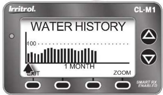
bar
WATER HISTORY | Timeframe | Value | | :--- | :--- | | 1 Month | 100 | | EXIT | (not visible on main display) | | ZOOM | (not visible on main display) | | SMART RX ENABLED | (no readable text or symbols)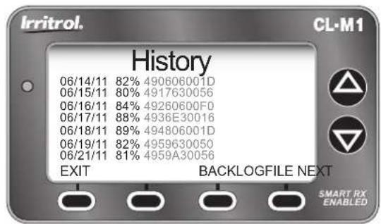
text_image
Irritrol. History 06/14/11 82% 490606001D 06/15/11 80% 4917630056 06/16/11 84% 49260600F0 06/17/11 88% 4936E30016 06/18/11 89% 494806001D 06/19/11 82% 4959630050 06/21/11 81% 4959A30056 EXIT BACKLOGFILE NEXT SMART RX ENABLEDWeather Sensor Identification Feature
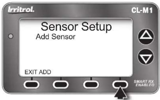
Within the Sensor Setup screen, the Weather Sensor ID can be easily viewed, and pairing removed/replaced as needed.
- From the Home screen, select the Main Menu Sensor option (MENU⇒SENSOR⇒ENTER). The ID number of the currently paired Weather Sensor will be displayed.
• To remove and replace the currently-paired Weather Sensor, press the REMOVE key to display the Remove Sensor screen.
⚠️ Important: A new Weather Sensor must be activated before it can be paired with the Receiver Module. See page 9 for details.
- Press YES key the display Sensor Setup/Add Sensor screen.
- Press the ADD key to initiate the sensor ID search function.
- Press and release the Weather Sensor Test Pin to "Ping" the Receiver Module. When pairing is successful, the 7-digit sensor ID is displayed.
text_image
Irritrol. Sensor Setup Add Sensor EXIT ADD SMART RX ENABLED CL-M1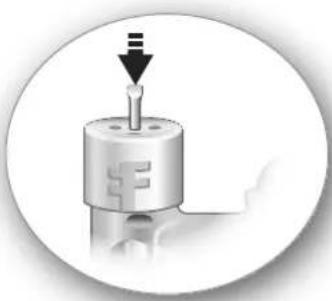
natural_image
Close-up of a mechanical component with a downward arrow and three symbols, no readable text or labels.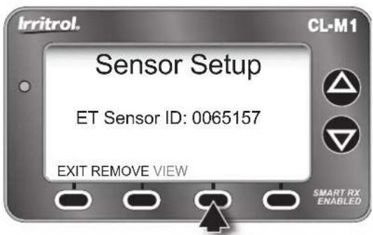
text_image
Irritrol. Sensor Setup ET Sensor ID: 0065157 EXIT REMOVE VIEW SMART RX ENABLED CL-M1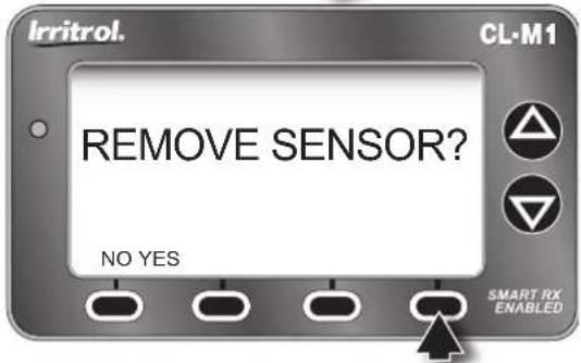
text_image
Irritrol. CL-M1 REMOVE SENSOR? NO YES SMART RX ENABLED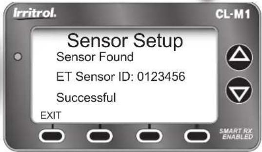
text_image
Irritrol. Sensor Setup Sensor Found ET Sensor ID: 0123456 Successful EXIT CL-M1 SMART RX ENABLEDControl System Synchronization
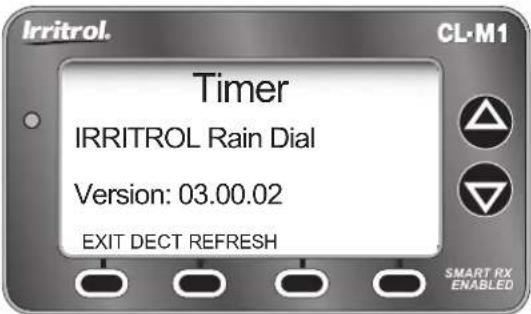
The Receiver Module and irrigation controller must remain synchronized for proper operation of Climate Logic system operations. The Timer option of the Main Menu provides the utility features that enable synchronization to be easily verified and updated as needed.
- From the Home screen, select the Main Menu, Timer option (MENU⇒TIMER⇒ENTER). The controller make, model and software version will be displayed.
- Press the REFRESH key as needed to update the controller information.
- Press the DECT (Detect) key to access the current controller time and date setting.
Remote PIN Setup
The irrigation controller can be accessed through the Receiver Module by a CL-R1 handheld remote device using the default 0000 PIN code. A unique PIN code can be applied to the Receiver Module to provide discrete remote control access as preferred.
- From the Home screen, select the Main Menu, Sensor option (MENU⇒SENSOR⇒ENTER).
- Press the or key to adjust the selected value.
- Press tNExT key to select the next value in sequence.
- When the PIN is displayed correctly, press the value key.
text_image
Irritrol. Timer IRRITROL Rain Dial Version: 03.00.02 EXIT DECT REFRESH SMART RX ENABLED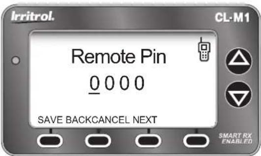
text_image
Irritrol. Remote Pin 0 0 0 0 SAVE BACKCANCEL NEXT CL-M1 SMART RX ENABLEDWeather Sensor Battery Replacement
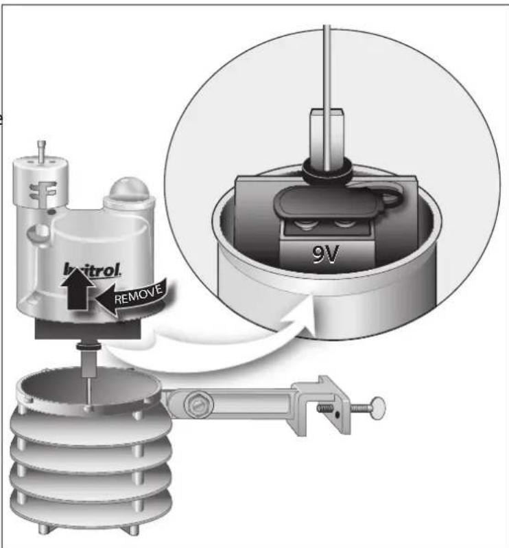
In normal operating conditions, the Weather Sensor's single, 9V-Alakaline battery can provide service up to five years. A loss of signal will result from a weak battery condition. Replace the battery as follows:
- The battery is stored in the upper half of the sensor housing. To access the battery, release and remove the upper housing by twisting it clockwise while holding the base stationary.
- Disconnect the battery wire clip. Remove the used battery and insert a fresh 9V-Alkaline battery between the foam pad and housing. Reconnect the battery wire clip.
• To reassemble the sensor housing, dress the antenna wire through the lower housing, exiting the center hole in the bottom grid. - Mate the halves squarely, aligning the translucent dome above the mounting bracket.
- Turn the upper housing counterclockwise to lock into lower housing (held stationary).
Note: Proper disposal of all batteries is very important for the environment and must comply with the battery manufacturer's recommended procedures.
text_image
Inletrol REMOVE 9VSpecifications
Weather Sensor/Transmitter, Model CL-W1
- 2.75" W x 5" H x 6.25" D (over bracket)
7 cm W x 12.7 cm H x 15.9 cm D (over bracket) - Battery: 9V-Alkaline, up to 5-year duration
- Antenna Wire:
1.5" L x 0.192 Dia.
3.81 cm L x 4.8 mm Dia.
• RF Reception Range: Up to 1000' (304 m) LOS
- Operating Temperature: 14–140 °F (-10°–60° C)
- Rain Sensing Method: Industry-standard, hygroscopic, stacked-disc style w/adjustable threshold
- Quick-Clip Mounting Bracket: Rain gutter/solid-surface mounting option w/vertical adjustment and stainless steel hardware.
• Visible RF Transmission LED
• UL, FCC and IC Approval
• FCC ID: OF7WS9
• IC: 3575A-WS9
Receiver Module, Model CL-M19
- Compatible with Remote-ready Irritrol and Toro Controllers and CL Series Handheld Remote
- Input Power (from controller): 5v DC
- LCD Screen Dimensions: 2.5" W x 1.25" H 6.35 cm W x 3.18 cm H
• LCD Contrast Adjustment
- Dimensions: 3.25" H (5.375" w/antenna) x 4.125" W x 0.75" D 8.26 cm H (13.16 cm w/antenna) x 10.48 cm W x 1.9 cm D
- Power/Date Cable: 20" L x 0.16 Dia. 50.8 cm L x 4.1 mm Dia. RJ14 connector
- Indoor/Outdoor Installation
- Weather-resistant Enclosure (with cover closed)
• UL, FCC and IC Approval
• FCC ID: OF7CL9
• IC: 3575A-CL9
FCC Information
This equipment generates and uses radio frequency energy and if not installed and used properly, that is, in strict accordance with the manufacturer's instructions, may cause interference to radio and television reception. It has been type tested and found to comply with the limits for a FCC Class B computing device in accordance with the specifications in Subpart J of Part 15 of FCC Rules, which are designed to provide reasonable protection against such interference in a residential installation. However, there is no guarantee that interference will not occur in a particular installation. If this equipment does cause interference to radio or television reception, which can be determined by turning the equipment off and on, the user is encouraged to try to correct the interference by one or more of the following measures:
- Reorient the receiving antenna
- Relocate the irrigation controller with respect to the receiver
- Move the irrigation controller away from the receiver
- Plug the irrigation controller into a different outlet so that the irrigation controller and receiver are on different branch circuits.
If necessary, the user should consult the dealer or an experienced radio/television technician for additional suggestions. The user may find the following booklet prepared by the Federal Communications Commission helpful: "How to Identify and Resolve Radio-TV Interference Problems." This booklet is available from the U.S. Government Printing Office, Washington, DC 20402. Stock No. 004-000-00345-4.
Notes
Notes:

At Irritrol, we recognize the importance of effective water management in the irrigation industry, and have been working hard to produce products that promote the responsible use of water.
The Water Saver ^® symbol accompanies each of our products that provide a significant water-savings opportunity. As you can see, the Climate Logic system proudly bears this distinctive symbol.