
700DK-1-MF - Faucets Irritrol - Free user manual and instructions
Find the device manual for free 700DK-1-MF Irritrol in PDF.


| Brand | Irritrol |
| Model | 700DK-1-MF |
| Product Type | Irrigation Controller |
| Number of Stations | 1 (Main Flow) |
| Power Supply | 24 VAC, 60 Hz |
| Dimensions (H x W x D) | 10 x 6 x 3 inches |
| Weight | 1.5 lbs |
| Operating Temperature | 32°F to 120°F (0°C to 49°C) |
| Maximum Water Pressure | 150 PSI |
| Maximum Flow Rate | 12 GPM |
| Enclosure Type | Indoor/Outdoor (Weather Resistant) |
| Protection Rating | NEMA 3R |
| Wiring | Common wire and one control wire |
| Installation | Wall mount or post mount |
| Warranty | 2 years limited |
| Maintenance | Clean filter regularly, check wiring |
| Safety | Disconnect power before servicing |
| Spare Parts Availability | Transformer, solenoid, valve body |
Frequently Asked Questions - 700DK-1-MF Irritrol
User questions about 700DK-1-MF Irritrol
0 question about this device. Answer the ones you know or ask your own.
Ask a new question about this device
Download the instructions for your Faucets in PDF format for free! Find your manual 700DK-1-MF - Irritrol and take your electronic device back in hand. On this page are published all the documents necessary for the use of your device. 700DK-1-MF by Irritrol.
USER MANUAL 700DK-1-MF Irritrol
Click on the links to view the documents.
Drip Zone Valve Kit
Models 2500DK-1-LF and 2500DK-1-MF
Installation Instructions
373-0512 Revision B
Drip Zone Valve Kit
Models 2711APRDK-LF and 2711APRDK-MF
Installation Instructions
373-0513 Revision B
Drip Zone Valve Kit
Models 2713APRDK-LF and 2713APRDK-MF
Installation Instructions
373-0514 Revision B
Drip Zone Valve Kit
Models 700DK-075-LF
Installation Instructions
373-0515 Revision B
Drip Zone Valve Kit
Models 700DK-1-LF and 700DK-1-MF
Installation Instructions
373-0516 Revision B
Drip Zone Kit - Less Valve
Models DK-LV-LF and DK-LV-MF
Installation Instructions
373-0535 Revision A
Drip Zone Valve Kit Models 2500DK-1-LF and 2500DK-1-MF Installation Instructions
Kit Components
- Irritrol 2500 Series Valve, Model 2500TF
- Pressure Regulator - 25 psi at 0.1–8 GPM, 3/4" Female NPT (Low Flow [LF] model)
- Pressure Regulator - 25 psi at 2–20 GPM, 3/4" Female NPT (Medium Flow [MF] model)
• 3/4" MPT x MPT F Series Y-filter, 150 Mesh Screen
• Drip Line Compression Adapter, CA-710
• 1" x 3/4" Male NPT Reducer Bushing
• 3/4" MPT x 1/2" Slip Fitting
Specifications
- Downstream Pressure Regulation: 25 psi
- Flow Rate at 25 psi: (LF Model) 0.1–8 GPM (MF Model) 2–20 GPM
• Filtration: 150 Mesh Stainless Steel Screen
• 1" In-line Electric Control Valve, Model 2500TF
♦ Operating Pressure: 10–150 psi
♦ 24 VAC, 50/60 Hz Solenoid
♦ Inrush: 0.40 amp, 9.6 VA
♦ Holding: 0.20 amp, 4.8 VA
• Manual On/Off - Internal and External Bleed - Adjustable Flow Control
Installation Procedure
CAUTION: When assembling the drip zone valve kit components, use just 1½ to 2 turns of PTFE tape on male threads. Never use pipe dope. To achieve a leak-free thread connection, turn the male fitting until it is finger-tight, and then add one or two more turns. Over-tightening can cause splitting and failure of the female threads.
⚠️ Important: Ensure the Y-filter, control valve and pressure regulator are installed in the correct flow orientation. Flow direction arrows are provided on each component. Refer to Figure 1.
- Thread the Y-filter inlet into the valve outlet with the provided 1" x 3/4" NPT reducer bushing. Use PTFE tape on all threaded connections. Angle the Y-filter slightly downward as shown in Figure 1.
- Thread the pressure regulator inlet into the Y-filter outlet.
- Connect the water source supply line and piping to drip emitters.
NOTE: Installing the valve assembly below grade in a valve box is recommended for protection and ease of service.
NOTE: Refer to the 2500TF Series Valve Instruction Guide provided in the kit for complete valve installation and operation information.
NOTE: To adapt the Drip Zone Valve Kit for dripline applications, install the provided 3/4" MPT x 1/2" Slip fitting and CA-710 dripline compression adapter to the pressure regulator outlet.
- Flush the system to remove debris.
- To determine the recommended minimum/maximum number of drip emitters per control valve, refer to the table below.
Table 1
| Emitter (GPH) | Low Flow | Medium Flow |
| 0.5 | 30–960 | 240–2400 |
| 1.0 | 15–480 | 120–1200 |
| 2.0 | 1–240 | 60–600 |

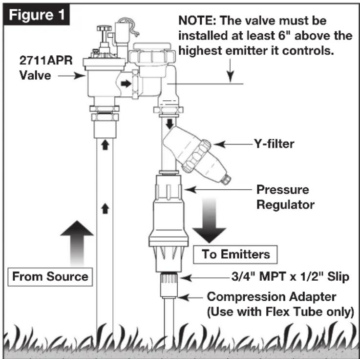
Drip Zone Valve Kit Models 2711APRDK-LF and 2711APRDK-MF Installation Instructions
Kit Components
- Irritrol 2700 Series Valve, Model 2711APR
- Pressure Regulator - 25 psi at 0.1–8 GPM, 3/4" Female NPT (Low Flow [LF] model)
- Pressure Regulator - 25 psi at 2–20 GPM, 3/4" Female NPT (Medium Flow [MF] model)
- 3/4" MPT x MPT F Series Y-filter, 150 Mesh Screen
• Drip Line Compression Adapter, CA-710 - 3/4" MPT x 1/2" Slip Fitting
Specifications
- Downstream Pressure Regulation: 25 psi
- Flow Rate at 25 psi: (LF Model) 0.1–8 GPM (MF Model) 2–20 GPM
• Filtration: 150 Mesh Stainless Steel Screen - 3/4" Anti-siphon Electric Control Valve, Model 2711APR
♦ Operating Pressure: 10–150 psi
♦ 24 VAC, 50/60 Hz Solenoid
♦ Inrush: 0.40 amp, 9.6 VA
♦ Holding: 0.20 amp, 4.8 VA - Manual On/Off - Internal and External Bleed
- Adjustable Flow Control
Installation Procedure
CAUTION: When assembling the drip zone valve kit components, use just 1½ to 2 turns of PTFE tape on male threads. Never use pipe dope. To achieve a leak-free thread connection, turn the male fitting until it is finger-tight, and then add one or two more turns. Over-tightening can cause splitting and failure of the female threads.
⚠️ Important: Ensure the Y-filter, control valve and pressure regulator are installed in the correct flow orientation. Flow direction arrows are provided on each component. Refer to Figure 1.
-
Thread the Y-filter inlet into the valve outlet. Use PTFE tape on all threaded connections. Angle the Y-filter slightly downward as shown in Figure 1.
-
Thread the pressure regulator inlet into the Y-filter outlet.
-
Connect the water source supply line and piping to drip emitters.
NOTE: Refer to the 2711APR Series Valve Instruction Guide provided in the kit for complete valve installation and operation information.
NOTE: To adapt the Drip Zone Valve Kit for dripline applications, install the provided 3/4" MPT x 1/2" Slip fitting and CA-710 dripline compression adapter to the pressure regulator outlet.
-
Flush the system to remove debris.
-
To determine the recommended minimum/maximum number of drip emitters per control valve, refer to the table below.
Table 1
| Emitter (GPH) | Low Flow | Medium Flow |
| 0.5 | 30–960 | 240–2400 |
| 1.0 | 15–480 | 120–1200 |
| 2.0 | 1–240 | 60–600 |
Kit Components
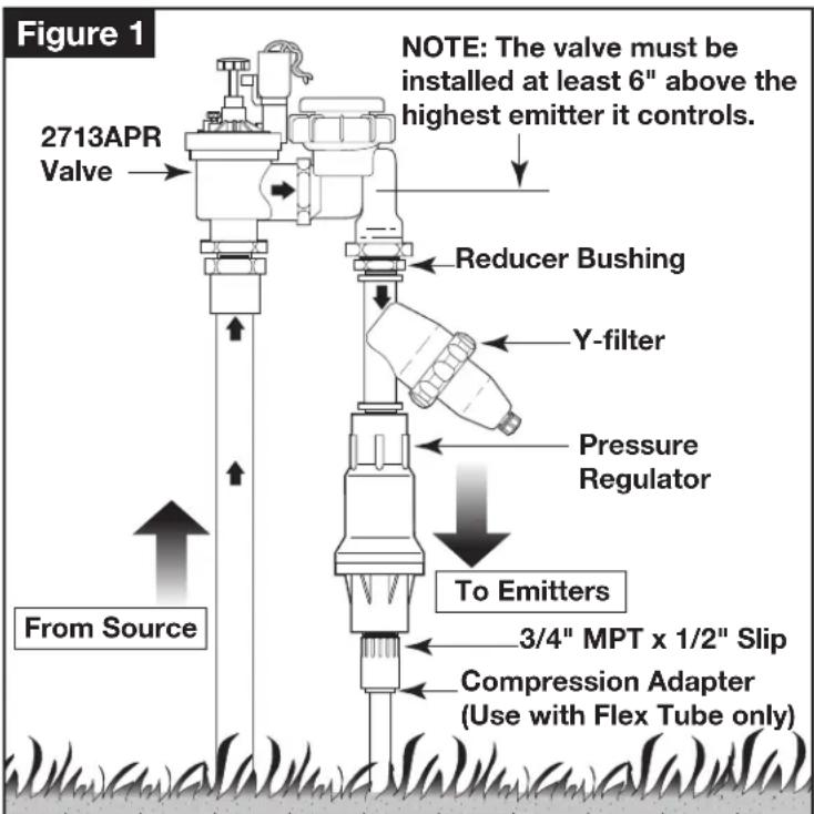
- Irritrol 2700 Series Valve, Model 2713APR
- Pressure Regulator - 25 psi at 0.1–8 GPM, 3/4" Female NPT (Low Flow [LF] model)
- Pressure Regulator - 25 psi at 2–20 GPM, 3/4" Female NPT (Medium Flow [MF] model)
- 3/4" MPT x MPT F Series Y-filter, 150 Mesh Screen
• Drip Line Compression Adapter, CA-710 - 1" x 3/4" Male NPT Reducer Bushing
- 3/4" MPT x 1/2" Slip Fitting
Specifications
- Downstream Pressure Regulation: 25 psi
- Flow Rate at 25 psi: (LF Model) 0.1–8 GPM (MF Model) 2–20 GPM
• Filtration: 150 Mesh Stainless Steel Screen
• 1" Anti-siphon Electric Control Valve, Model 2713APR
♦ Operating Pressure: 10–150 psi
♦ 24 VAC, 50/60 Hz Solenoid
♦ Inrush: 0.40 amp, 9.6 VA
♦ Holding: 0.20 amp, 4.8 VA - Manual On/Off - Internal and External Bleed
- Adjustable Flow Control
Installation Procedure
CAUTION: When assembling the drip zone valve kit components, use just 1½ to 2 turns of PTFE tape on male threads. Never use pipe dope. To achieve a leak-free thread connection, turn the male fitting until it is finger-tight, and then add one or two more turns. Over-tightening can cause splitting and failure of the female threads.
⚠️ Important: Ensure the Y-filter, control valve and pressure regulator are installed in the correct flow orientation. Flow direction arrows are provided on each component. Refer to Figure 1.
- Thread the Y-filter inlet into the valve outlet with the provided 1" x 3/4" NPT reducer bushing. Use PTFE tape on all threaded connections. Angle the Y-filter slightly downward as shown in Figure 1.
- Thread the pressure regulator inlet into the Y-filter outlet.
- Connect the water source supply line and piping to drip emitters.
NOTE: Refer to the 2713APR Series Valve Instruction Guide provided in the kit for complete valve installation and operation information.
NOTE: To adapt the Drip Zone Valve Kit for dripline applications, install the provided 3/4" MPT x 1/2" Slip fitting and CA-710 dripline compression adapter to the pressure regulator outlet.
- Flush the system to remove debris.
- To determine the recommended minimum/maximum number of drip emitters per control valve, refer to the table below.
Table 1
| Emitter (GPH) | Low Flow | Medium Flow |
| 0.5 | 30–960 | 240–2400 |
| 1.0 | 15–480 | 120–1200 |
| 2.0 | 1–240 | 60–600 |
Kit Components
- Irritrol 700 Series Valve, Model 700B-.75
- Pressure Regulator - 25 psi at 0.1–8 GPM, 3/4" Female NPT
• 3/4" MPT x MPT F Series Y-filter, 150 Mesh Screen
• Drip Line Compression Adapter, CA-710
• 3/4" MPT x 1/2" Slip Fitting
Specifications
- Downstream Pressure Regulation: 25 psi
• Flow Rate at 25 psi: 0.1–8 GPM
• Filtration: 150 Mesh Stainless Steel Screen
• 1" In-line Electric Control Valve, Model 700B-.75
♦ Operating Pressure: 10–150 psi
♦ 24 VAC, 50/60 Hz Solenoid
• Inrush: 0.40 amp, 9.6 VA
♦ Holding: 0.20 amp, 4.8 VA - Manual On/Off - Internal and External Bleed
- Adjustable Flow Control
Installation Procedure
CAUTION: When assembling the drip zone valve kit components, use just 1 ½ to 2 turns of PTFE tape on male threads. Never use pipe dope. To achieve a leak-free thread connection, turn the male fitting until it is finger-tight, and then add one or two more turns. Over-tightening can cause splitting and failure of the female threads.
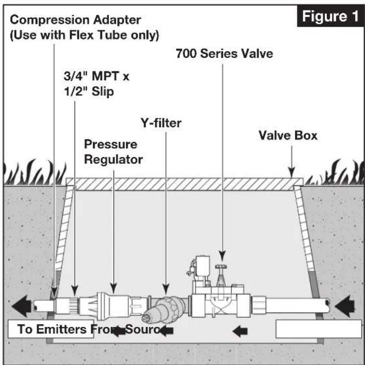
⚠️ Important: Ensure the Y-filter, control valve and pressure regulator are installed in the correct flow orientation. Flow direction arrows are provided on each component. Refer to Figure 1.
- Thread the Y-filter inlet into the valve outlet. Use PTFE tape on all threaded connections. Angle the Y-filter slightly downward as shown in Figure 1.
- Thread the pressure regulator inlet into the Y-filter outlet.
- Connect the water source supply line and piping to drip emitters.
NOTE: Installing the valve assembly below grade in a valve box is recommended for protection and ease of service.
NOTE: Refer to the 700 Series Valve Instruction Guide provided in the kit for complete valve installation and operation information.
NOTE: To adapt the Drip Zone Valve Kit for dripline applications, install the provided 3/4" MPT x 1/2" Slip fitting and CA-710 dripline compression adapter to the pressure regulator outlet.
- Flush the system to remove debris.
- To determine the recommended minimum/maximum number of drip emitters per control valve, refer to the table below.
Table 1
| Emitter (GPH) | Low Flow | Medium Flow |
| 0.5 | 30–960 | 240–2400 |
| 1.0 | 15–480 | 120–1200 |
| 2.0 | 1–240 | 60–600 |
Irritrol®
Get more done™
Drip Zone Valve Kit Models 700DK-1-LF and 700DK-1-MF Installation Instructions
Kit Components
- Irritrol 700 Series Valve, Model 700-1
- Pressure Regulator - 25 psi at 0.1–8 GPM, 3/4" Female NPT (Low Flow [LF] model)
- Pressure Regulator - 25 psi at 2–20 GPM, 3/4" Female NPT (Medium Flow [MF] model)
• 3/4" MPT x MPT F Series Y-filter, 150 Mesh Screen
• Drip Line Compression Adapter, CA-710
• 1" x 3/4" Male NPT Reducer Bushing
• 3/4" MPT x 1/2" Slip Fitting
Specifications
- Downstream Pressure Regulation: 25 psi
- Flow Rate at 25 psi: (LF model) 0.1–8 GPM (MF model) 2–20 GPM
• Filtration: 150 Mesh Stainless Steel Screen
• 1" In-line Electric Control Valve, Model 700-1
♦ Operating Pressure: 10–150 psi
• 24 VAC, 50/60 Hz Solenoid
♦ Inrush: 0.40 amp, 9.6 VA
♦ Holding: 0.20 amp, 4.8 VA - Manual On/Off - Internal and External Bleed
- Adjustable Flow Control
Installation Procedure
CAUTION: When assembling the drip zone valve kit components, use just 1 12 to 2 turns of PTFE tape on male threads. Never use pipe dope. To achieve a leak-free thread connection, turn the male fitting until it is finger-tight, and then add one or two more turns. Over-tightening can cause splitting and failure of the female threads.
⚠️ Important: Ensure the Y-filter, control valve and pressure regulator are installed in the correct flow orientation. Flow direction arrows are provided on each component. Refer to Figure 1.
- Thread the Y-filter inlet into the valve outlet with the provided 1" x 3/4" NPT reducer bushing. Use PTFE tape on all threaded connections. Angle the Y-filter slightly downward as shown in Figure 1.
- Thread the pressure regulator inlet into the Y-filter outlet.
- Connect the water source supply line and piping to drip emitters.
NOTE: Installing the valve assembly below grade in a valve box is recommended for protection and ease of service.
NOTE: Refer to the 700 Series Valve Instruction Guide provided in the kit for complete valve installation and operation information.
NOTE: To adapt the Drip Zone Valve Kit for dripline applications, install the provided 3/4" MPT x 1/2" Slip fitting and CA-710 dripline compression adapter to the pressure regulator outlet.
- Flush the system to remove debris.
- To determine the recommended minimum/maximum number of drip emitters per control valve, refer to the table below.
Table 1
| Emitter (GPH) | Low Flow | Medium Flow |
| 0.5 | 30–960 | 240–2400 |
| 1.0 | 15–480 | 120–1200 |
| 2.0 | 1–240 | 60–600 |

Irritrol®
Get more done™
Drip Zone Kit - Less Valve Models DK-LV-LF and DK-LV-MF Installation Instructions
Kit Components
- Pressure Regulator - 25 psi at 0.1–8 GPM, 3/4" Female NPT (Low Flow [LF] model)
- Pressure Regulator - 25 psi at 2–20 GPM, 3/4" Female NPT (Medium Flow [MF] model)
• 3/4" MPT x MPT F Series Y-filter, 150 Mesh Screen
• Drip Line Compression Adapter, CA-710 - 1" x 3/4" Male NPT Reducer Bushing
• 3/4" MPT x 1/2" Slip Fitting
Specifications
• Maximum Supply Pressure: 150 psi
- Downstream Pressure Regulation: 25 psi
- Flow Rate at 25 psi: (LF model) 0.1–8 GPM (MF model) 2–20 GPM
• Filtration: 150 Mesh Stainless Steel Screen
Installation Procedure
CAUTION: When assembling the drip zone kit components, use just 1 ½ to 2 turns of PTFE tape on male threads. Never use pipe dope. To achieve a leak-free thread connection, turn the male fitting until it is finger-tight, and then add one or two more turns. Over-tightening can cause splitting and failure of the female threads.
⚠️ Important: Ensure the Y-filter and pressure regulator are installed in the correct flow orientation. Flow direction arrows are provided on each component. Refer to Figure 1.
- Thread the pressure regulator inlet into the Y-filter outlet.
- Connect the water source supply line and piping to drip emitters.
NOTE: Installing the assembly below grade in a valve box is recommended for protection and ease of service.
NOTE: To adapt the Drip Zone Kit for dripline applications, install the provided 3/4" MPT x 1/2" Slip fitting and CA-710 dripline compression adapter to the pressure regulator outlet.
-
Flush the system to remove debris.
-
To determine the recommended minimum/maximum number of drip emitters per control valve, refer to the table below.
Table 1
| Emitter (GPH) | Low Flow | Medium Flow |
| 0.5 | 30–960 | 240–2400 |
| 1.0 | 15–480 | 120–1200 |
| 2.0 | 1–240 | 60–600 |

© Irritrol • www.irritrol.com • For Technical Assistance, call 1-800-333-3125 Part Number 373-0535 revision A
- Drip Zone Valve Kit Models 2500DK-1-LF and 2500DK-1-MF Installation Instructions
- Kit Components
- Specifications
- Installation Procedure
- Drip Zone Valve Kit Models 2711APRDK-LF and 2711APRDK-MF Installation Instructions
- Irritrol®
- Drip Zone Valve Kit Models 700DK-1-LF and 700DK-1-MF Installation Instructions
- Drip Zone Kit - Less Valve Models DK-LV-LF and DK-LV-MF Installation Instructions
Brand : Irritrol
Model : 700DK-1-MF
Category : Faucets