
540 - Water heaters Baxi - Free user manual and instructions
Find the device manual for free 540 Baxi in PDF.


| Product Type | Electric Storage Water Heater |
| Brand | Baxi |
| Model | 540 |
| Category | Water Heater and Hot Water Tank |
| Capacity | 40 Liters |
| Power Consumption | 1500 W |
| Voltage | 230 V / 50 Hz |
| Dimensions (H x W x D) | 800 x 400 x 400 mm |
| Weight | 15 kg |
| Energy Efficiency Class | C |
| Safety Valve | Included (Temperature & Pressure Relief) |
| Thermostat | Adjustable, 30°C - 75°C |
| Material | Enameled Steel Tank with Magnesium Anode |
| Installation Type | Wall Mounted (Vertical) |
| Max Operating Pressure | 8 bar |
| Protection | IPX4 |
| Maintenance | Annual inspection of anode and pressure relief valve |
Frequently Asked Questions - 540 Baxi
User questions about 540 Baxi
0 question about this device. Answer the ones you know or ask your own.
Ask a new question about this device
Download the instructions for your Water heaters in PDF format for free! Find your manual 540 - Baxi and take your electronic device back in hand. On this page are published all the documents necessary for the use of your device. 540 by Baxi.
USER MANUAL 540 Baxi
Low Temperature Boiler
Installation, Assembly
and Operating Instructions
for the INSTALLER
natural_image
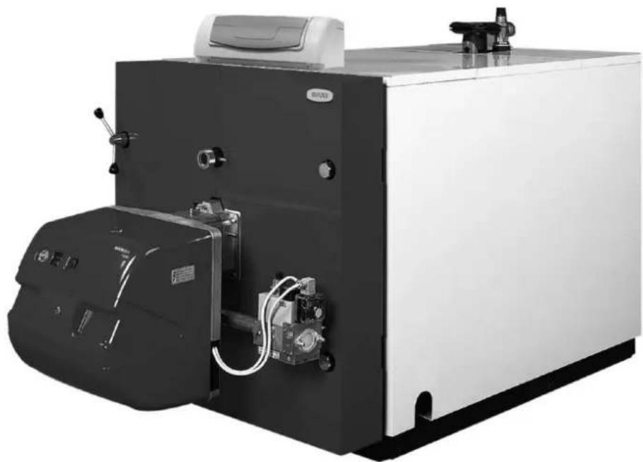
Exterior view of a large industrial gas stove or pressure vessel with control panel and fan (no visible text or symbols)Fig.1
(CPA 55 -170) (CPA 220-1750)

E: 1/20
| Modelo Dimensiones en mm. | |||||||||||||||||||
| Boiler type Dimensions in mm | |||||||||||||||||||
| Modelo Dimensões en mm | |||||||||||||||||||
| A B C D E F G H I J K L M | N a | b c d e | |||||||||||||||||
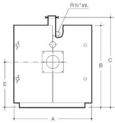
| CPA 55-BTH | 810 | 870 | 945 | 1.254 | 465 | 665 | 175 | 279 | 240 | 105 | - | 874 | 92 | - | 2" | 2" | 114" | 1^* | 314" |
| CPA 70-BTH | 810 | 870 | 945 | 1.394 | 465 | 665 | 175 | 419 | 240 | 105 | - | 1.014 | 92 | - | 2" | 2" | 114" | 1^* | 314" |
| CPA 100-BTH | 880 | 940 | 1.015 | 1.394 | 500 | 720 | 195 | 373 | 240 | 105 | - | 1.014 | 92 | - | DN 65 | DN 65 | 112" | 114" | 1" |
| CPA 130-BTH | 880 | 940 | 1.015 | 1.494 | 500 | 720 | 195 | 473 | 240 | 105 | - | 1.114 | 92 | - | DN 65 | DN 65 | 112" | 114" | 1^* |
| CPA 170-BTH | 880 | 940 | 1.015 | 1.608 | 500 | 720 | 195 | 587 | 240 | 105 | - | 1.228 | 92 | - | DN 65 | DN 65 | 112" | 114" | 1^* |
| CPA 220-BTH | 980 | 1.070 | 1.162 | 1.665 | 575 | 825 | 245 | 495 | 346 | 181 | 115 | 1.250 | 110 | 336 | DN 80 | DN 80 | 2^* | 112" | 114" |
| CPA 270-BTH | 980 | 1.070 | 1.162 | 1.815 | 575 | 825 | 245 | 645 | 346 | 181 | 115 | 1400 | 110 | 336 | DN 80 | DN 80 | 2^* | 112" | 114" |
| CPA 320-BTH | 980 | 1.070 | 1.162 | 1.915 | 575 | 825 | 245 | 745 | 346 | 181 | 115 | 1.500 | 110 | 336 | DN 80 | DN 80 | 2^* | 112" | 114" |
| CPA 380-BTH | 1.080 | 1.190 | 1.284 | 1.940 | 645 | 920 | 295 | 760 | 346 | 181 | 133 | 1.525 | 128 | 336 | DN 100 | DN 100 | 2^* | 112" | 114" |
| CPA 460-BTH | 1.080 | 1.190 | 1.284 | 2.155 | 645 | 920 | 295 | 976 | 346 | 181 | 133 | 1.741 | 128 | 336 | DN 100 | DN 100 | 2^* | 112" | 114" |
| CPA 540-BTH | 1.210 | 1.320 | 1.412 | 2.195 | 710 | 1.025 | 345 | 949 | 406 | 216 | 135 | 1.761 | 110 | 356 | DN 100 | DN 100 | 212" | 2^* | 114" |
| CPA 640-BTH | 1.210 | 1.320 | 1.412 | 2.365 | 710 | 1.025 | 345 | 1.119 | 406 | 216 | 135 | 1.931 | 110 | 356 | DN 100 | DN 100 | 212" | 2^* | 114" |
| CPA 750-BTH | 1.320 | 1.440 | 1.537 | 2.365 | 775 | 1.095 | 395 | 979 | 476 | 286 | 142 | 1.931 | 118 | 356 | DN 125 | DN 125 | 212" | 2^* | 114" |
| CPA 900-BTH | 1.320 | 1.440 | 1.537 | 2.485 | 775 | 1.095 | 395 | 1.099 | 476 | 286 | 142 | 2.051 | 118 | 356 | DN 125 | DN 125 | 212" | 2^* | 114" |
| CPA 1100-BTH | 1.320 | 1.440 | 1.537 | 2.757 | 775 | 1.095 | 395 | 1.369 | 477 | 287 | 142 | 2.323 | 118 | 357 | DN 125 | DN 125 | 212" | 2^* | 114" |
| CPA 1300-BTH | 1.540 | 1.690 | 1.789 | 2.782 | 910 | 1.340 | 445 | 1.229 | 547 | 327 | 134 | 2.323 | 120 | 382 | DN 150 | DN 150 | 3^* | 212" | 2^* |
| CPA 1500-BTH | 1.540 | 1.690 | 1.783 | 2.972 | 910 | 1.340 | 445 | 1.419 | 547 | 327 | 134 | 2.513 | 120 | 382 | DN 150 | DN 150 | 3^* | 212" | 2^* |
| CPA 1750-BTH | 1.540 | 1.690 | 1.783 | 3.162 | 910 | 1.340 | 445 | 1.609 | 547 | 327 | 134 | 2.703 | 120 | 382 | DN 150 | DN 150 | 3^* | 212" | 2^* |
Fig. 2
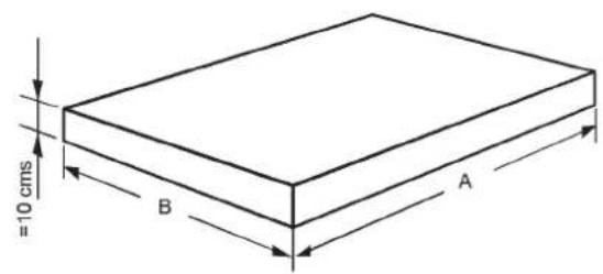
CPA-BTH 55 70 100 130 170 220 270 320 380 460 540 640 750 900 1100 1300 1500 1750
A cm. 95 110 110 120 130 130 150 160 160 185 185 200 200 210 240 240 260 280
B cm 90 90 100 100 100 110 110 110 120 120 131 131 142 142 142 164 164 164
Fig.3

line
| kW | Diameter o lado quadrado (cm) | Altura chimoncus (m) | |------|-------------------------------|----------------------| | 100 | 10 | 38 | | 70 | 20 | 38 | | 55 | 30 | 38 | | 130 | 40 | 38 | | 170 | 50 | 38 | | 220 | 60 | 38 | | 270 | 70 | 38 | | 320 | 80 | 38 | | 380 | 90 | 38 | | 460 | 100 | 38 | | 540 | 110 | 38 | | 640 | 120 | 38 | | 750 | 130 | 38 | | 900 | 140 | 38 | | 1100 | 150 | 38 | | 1300 | 160 | 38 | | 1500 | 170 | 38 | | 1750 | 180 | 38 |Fig.4


Cuadro básico / Quadro básico / Basic control panel (1 etapa / 1 stage)

Cuadro básico / Quadro básico/ Basic control panel (2 etapas / 2 stage)

Cuadro digital KSF/Quadro digital KSF / KSF digital control panel (1 etapa, 2 etapas y modulante) / (1 etapa, 2 etapas e modulante) (1 stage, 2 stage and modulating)

Fig. 5 Fig. 6


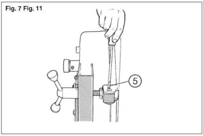


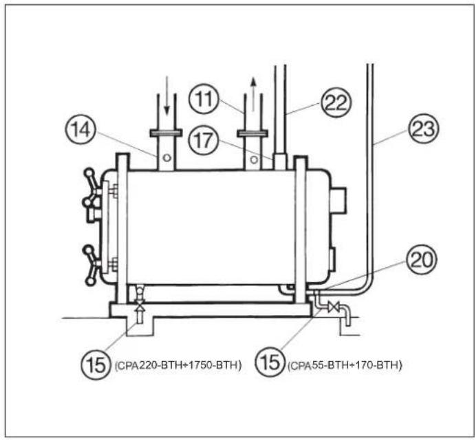


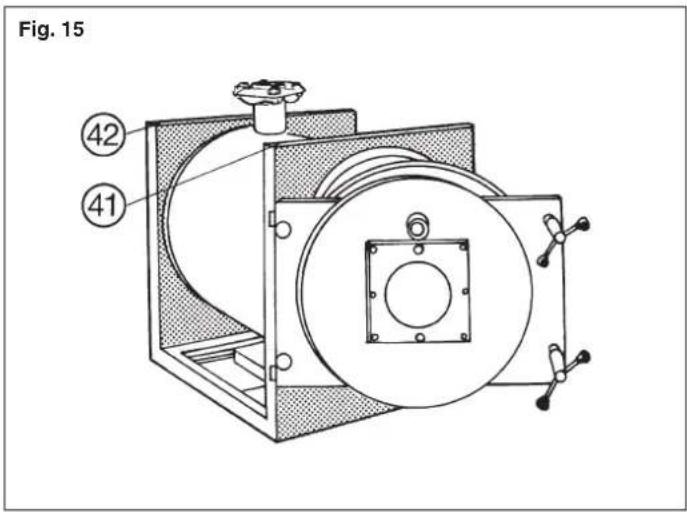
Fig. 17
I/O : Interruptor general (8)
C1 : 3-phase Contactor for Burner Feed (not supplied)
C2 : 3-phase Contactor for Burner Feed (not supplied)
T1-T2: 1 st Stage (low fire) Control Terminals
T6-T8 : 2 nd Stage (high fire) Control Terminals
Re1 : 1 st Stage Control Relay
Re2 : 2nd Stage Control Relay
1/8 : Main On/off Switch (8)*
: Power "on" Indicator Lamp (64)*
: Limit thermostat (35)*
C: 1 st & 2nd Stage Control Thermostat (34)*
h1 : 1 st Stage Hours Run Counter (68)*
h2 : 2 nd Stage Hours Run Counter (69)*
: 1 st Stage Operating Indicator Lamp (65)*
: 2 nd Stage Operating Indicator Lamp (66)*
: Burner "lockout" Indicator Lamp (67)*
1 : Boiler Control Panel Terminal Strip
2 : 7 pole plug
3 : 4 pole plug
4 : Burner Terminal Strip
5 : 5 pole plug
X - X á To be wired by the Installer.
Y - Y á Boiler Control Panel Connection (factory-wired)
Note: In gas burners the electrical components on the gas train will be connected in accordance with the instructions for the burner.
* These components are shown in Fig. 4.
Fig. 20 Legenda esquemas Fig. 17 ÷ 19
A : Circulador
B : Queimador
- Connectors and burner connection cables, supplied with the KSF control panel
- Only X7 connector must be used with one stage burner
- Set 5770 parameter according to one or two stage burner operation
- D: Door safety switch. Any other safety component must be connected in series with the door switch
Fig. 22
CONEXIONADO CUADRO KSF CON QUEMADORES MODULANTES / LIGAÇÃO QUADRO KSF - QUEIMADORES MODULANTES/ KSF CONTROL PANEL WIRING WITH MODULATING BURNER CRONO 8-GM, CRONO 15-GM, CRONO 20-GM, TECNO 34-GM, TECNO 44-GM

Notas:
- Connectors and burner connection cables, supplied with the KSF control panel
- Set 5770 parameter according to modulating burner operation
- Neither modulation Kit nor RWF 40 temperature controller is needed
- D: Door safety switch. Any other safety component must be connected in series with the door switch.
- We suggest to set parameter 2233 to 15; parameter 2234 to 20; parameter 2235 to 2,5 and parameter 2232 to the running time of the servomotor (between 24 and 42 seconds depending of the model. See burner instruccions manual)
Fig. 23
CONEXIONADO CUADRO KSF CON QUEMADORES MODULANTES / LIGAÇÃO QUADRO KSF - QUEIMADORES MODULANTES/ KSF CONTROL PANEL WIRING WITH MODULATING BURNER TECNO 28-GM, TECNO 38-GM, TECNO 50-GM, TECNO 70-GM, TECNO 100-GM, TECNO 130-GM, TECNO 190-GM, TECNO 50-LM, TECNO 70-LM, TECNO 100-LM, TECNO 130-LM, TECNO 190-LM

MB
Regleta quemador
Régua queimador
Burner terminal strip
Notas:
- Get rid of the X4 and X7 connectors and make the connections as shown
- Set 5770 parameter according to modulating burner operation
- Neither modulation Kit nor RWF 40 temperature controller is needed
- D: Door safety switch. Any other safety component must be connected in series with the door switch.
- We suggest to set parameter 2233 to 15; parameter 2234 to 20; parameter 2235 to 2,5 and parameter 2232 to the running time of the servomotor (between 24 and 42 seconds depending of the model. See burner instruccions manual)


Fig. 26


Fig. 27

Fig. 28

| Modelo CPA ∅ | A | B | C | D | E | |||
| 55-BTH 135 138 | 116 M8 | M8 | ||||||
| 70-BTH 135 138 | 116 M8 | M8 | ||||||
| 100-BTH 135 138 | 116 M8 | M8 | ||||||
| 130-BTH 135 138 | 116 M8 | M8 | ||||||
| 170-BTH 135 138 | 116 M8 | M8 | ||||||
| 220-BTH 155 158 | 130 M8 | M10 | ||||||
| 270-BTH 155 158 | 130 M8 | M10 | ||||||
| 320-BTH 155 158 | 130 M8 | M10 | ||||||
| 380-BTH 185 195 | 160 M10 | M12 | ||||||
| 460-BTH 185 195 | 160 M10 | M12 | ||||||
| 540-BTH 185 195 | 160 M10 | M12 | ||||||
| 640-BTH 185 195 | 160 M10 | M12 | ||||||
| 750-BTH 195 230 | -- M12 | |||||||
| 900-BTH 195 230 | -- M12 | |||||||
| 1100-BTH 195 230 | -- M12 | |||||||
| 1300-BTH 230 255 | 210 M12 | M16 | ||||||
| 1500-BTH 230 255 | 210 M12 | M16 | ||||||
| 1750-BTH 230 255 | 210 M12 | M16 | ||||||
Tab. 1
| CPA55-BTH | CPA70-BTH | CPA100-BTH | CPA130-BTH | CPA170-BTH | CPA220-BTH |
| CPA270-BTH | CPA320-BTH | CPA380-BTH | CPA460-BTH | CPA540-BTH | CPA640-BTH |
| CPA750-BTH | CPA900-BTH | CPA1100-BTH | CPA1300-BTH | CPA1500-BTH | CPA1750-BTH |
| CPA55-BTH | CPA70-BTH | CPA100-BTH | CPA130-BTH | CPA170-BTH | CPA220-BTH |
| CPA270-BTH | CPA320-BTH | CPA380-BTH | CPA460-BTH | CPA540-BTH | CPA640-BTH |
| CPA750-BTH | CPA900-BTH | CPA1100-BTH | CPA1300-BTH | CPA1500-BTH | CPA1750-BTH |
The CPA-BTH boiler is a heat generator with reverse flame and efficiency in excess of 93% (nett).
The main material used in the construction of this boiler is steel sheet. The material, methods of welding, method of construction and dimensions according to the existing regulations in the EEC. Key features of the CPA-BTH boiler are the top located Flow and Return connections and the reversibility of the combustion chamber door, which can be easily adapted for left or right hand opening according to the needs of the installation. From model CPA 70-BTH, boilers are fitted with an explosion relief gate situated in the smokehood. All models feature a door opening safety switch.
The boiler flue tubes are fitted with spiral-type turbulators with the leading part manufactured from stainless steel (except CPA 55, 70 y 100-BTH), which provide the necessary resistance to the passage of the products of combustion to achieve high operating efficiency.
The boiler body is insulated with a 70 mm-thick insulating blanket. The boiler is suitable for oil or gas firing, depending on the jet burner that is used. These burners must be according to the EC Directives and prepared for the local supply conditions and technical features of the boiler, described in this manual.
Delivery
CPA-BTH boilers are delivered in three packages: Package 1
Boiler body with the turbulators fitted in the bank of tubes.
Inside the combustion chamber is the insulating blanket for the boiler body, the door clamps with backnuts and cleaning brush.
Package 2
Outer casing; inside the packing is a plastic bag containing the screws for assembly, the bands for fixing the insulating blanket and the inspection window with gasket, the thermostat pocket and the grommets.
In models with basic control panel (one or two stage operation), the panel is delivered with the casing package, including its fixing screws.
Package 3
KSF digital control panel with models ordered with this panel.
Legislation and CE Marking
Boilers have been designed and manufactured according to the following standards:
- EN 303-1: Heating boilers with forced draught burners. Terminology, general requirements, testing and marking.
- EN 303-2: Heating boilers with forced draught burners. Special requirements for boilers with atomizing oil burners.
- EN 304: Heating boilers. Test code for heating boilers for atomizing oil boilers
- EN 303-3: Gas fired central heating boilers. Assembling comprising a boiler body and a forced draught burner
- EN 267: Forced draught oil burners.
Definitions, requirements, testing and marking
- EN 676: Automatic forced draught burners for gaseous fuels
Boilers are according to the following Directives: - Efficiency Directive 92/42/EEC. Articles 7(2),8 and Annexes III to V.
- Electromagnetic Compatibility Directive 2014/30/UE
- Low Voltage Directive 2014/35/UE
- Pressure Equipment Directive 2014/68/UE, article 4.3
Gas Appliances Regulation (EU) 2016/426
- Ecodesign Directive 2009/125/EC. Regulation N° 813/2013, article 1, part 2g (models up to 400 kW output)
The UE Declaration and Certificates are available and can be downloaded from our website www.baxi.es
Note:
The manufacturer responsibility concerning the CE marking is subject to be used the BAXI burners showed in the CE Certificates or any other burner of the market with the CE marking and with a firing rate suitable to the working conditions and technical features explained in this manual.
Notes relating to the burners
Boilers with an output lower than 400 kW (CPA 55-BTH to CPA 380-BTH models), are delivered without burner because according to the Comission Regulation N°813/2013, they are a product intended for replacing the existing CPA boilers in the market. However, the boiler are ready for assembling the BAXI burners recommended in Table 1. For the use with other burners, the following remarks must be taken into account:
- Burners must be according to EN 267 (with oil) or EN 676 (with Gas) and the EEC Directives (Electromagnetic Compatibility 2004/108/EEC, Low Voltage 2006/95/EEC, Machinery 2006/42/EEC) and Gas 2009/142/EEC)
- The boiler has a burner plate in the door with the dimensions showed in fig.28
- The burner must have an useful working field suitable for the combustion chamber overpressure showed in Table 1.
- The height above sea level where the boiler is installed must be taken into account as well, due to a decrease of the air density and consequently a lower quantity of the required oxygen for the combustion.
Technical specifications and dimensions
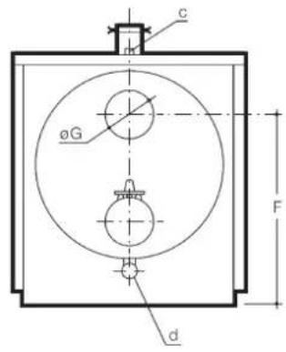
In Table 1 is summarized the main technical parameters for the range an in the Fig.1 is showed the general dimensions for the boilers and details about hydraulic connexions and chimney connection
Installation
When installing the boiler, the following MUST be observed:
– Respect the current regulations
- The complete installation and assembly of the boiler and its auxiliary components (burner, gas train, fuel supply, etc) must be carried out by authorized personnel only.
- The installation position must be in the form of a fireproof base which must be smooth and level and capable of supporting the weight of the boiler when full of water. Dimensions for boiler bases are shown in Fig. 2.
- The boiler plantroom and the ventilation provision must comply with the requirements contained in the Regulations for Central Heating Systems.
- The chimney shall be constructed in accordance with current standards and should take into account the requirements of local regulations on chimney heights. Guidance on chimney sizing is given in the graph Fig. 3.
- When fitting approved chimneys, the manufacturer's specifications must be observed.
Chimney Selection Graph. Fig. 3
Example: Find out the inside diameter of a chimney for a CPA 540-BTH and 15 m high.
According to the graph: Diameter = 36 cm. In any case, the recommendations of the chimney manufacturer, must be taken into account.
Assembly
Once the boiler has been set into place, follow the operations described below:
1 - Open the boiler door and remove the protective cardboard from the insulating fibre on it. Remove all the material contained in the combustion chamber (control panel, boiler body insulation, cleaning brush and door clamps).
2 - Fit the clamps (1) with their backnuts (2) in the door. See Fig. 5.
3 - Check that the opening direction of the door is the one required. On the other hand, if you want to reverse it, proceed as follows:
3.1 - Make sure the door is correctly fastened with the clamps (1) and hinge tie-rods (3).
3.2 - Transfer the M4 bolts (4), which locked the hinges on the side where the clamps were initially, to the opposite side (5) where the clamps will remain permanently. See Figs 6 and 7.
3.3 - Exchange, diagonally, each clamp (1) for a hinge tie-rod (3), keeping in each case the respective backnuts. See Fig. 8.
3.4 - Tighten the two backnuts (6) on the hinge side.
3.5 – Remove the door switch (7) and install it on the opposite side.
4 - IMPORTANT
The door will be adjusted in this mounting position so as to prevent flue gases from leaking.
(This adjustment should be made before fitting the door casing panel and the burner). To adjust the door, for making sure that it is gas-tight, proceed as follows:
Likewise, loosen the backnut (2) on the side of the door clamps. Fig. 25.
Tighten the two hinge tie-rods (3) in parallel with the two clamps (1) until the whole outline of the door sinks about 2 to 3 mm in the sealing strip.
5 - Place the pocket (9) for the thermostat and thermometer bulbs in the socket (10) of the heating flow pipe (11).
In models with basic control panel (one or two stage operation), place the check valve (12) of the combined temp./altitude gauge in the socket (13) of the return pipe (14). In both cases put teflon or something similar on the thread to ensure water tightness. See Fig. 9.
6 - Make the flow (11) and return (14) connections from the boiler to the heating installation.
7 - Make the safety and drain connections (15) in accordance with the type of installation:
7.1 – Sealed System Installation. Fig. 10 Where the hydraulic installation is to be sealed and pressurised, a safety valve (16) must be connected to the upper tapping (17) adjacent to the flow connection. Under no circumstances must the setting of the safety valve exceed 5 bar or the maximum pressure allowed by the expansion vessel. The discharge pipe should be connected via a funnel (18) to the drain.
A tapping is provided for connection of an expansion vessel (19) via a tube (20) to the underside of the boiler body. An automatic air vent (21) should be installed to bleed the air in the tube (20).
7.2 - Open Vented Installation. Fig. 11
Where the hydraulic installation is to be open vented, the vent pipe (22) should be connected to the upper tapping (17) and the cold feed pipe (23) must be connected to the connection (20) at the base of the boiler body.
8 - Fill the installation with water and test for water tightness, checking that there are no leaks. Drain/flush the installation to remove debris and then refill.
9 - Insulate the boiler by wrapping the exterior of the body cylinder with the 70mm glass fibre insulating blanket (24). It will be necessary to cut apertures for the various connections that will pass through the insulation. With some models, the blanket is in two parts, and any excess should be overlapped at the centre of the body.
Fix in place the insulating blanket with the bands (25) and lock in place using the buckle (26) as shown in the drawing.
Where the insulation is in two parts, the central band (25) should be positioned at the overlap of the two pieces. See Fig. 12.
10- Insert the cable grommets into the holes (26) in the lower, front & rear boiler end panels. Left or right hand holes should be used to match the handing of the door.
11 - Take the control panel and the top front panel of the casing.
Boilers with basic control panel (one stage)
11.1 - Fix the control panel (29) to the panel (30) with the four screws supplied.
Straighten up the capillary tubes of the thermostats and thermometer (31), introduce the bulbs in the pocket (9) and fix them with the incorporated clip.
Straighten up the capillary tube of the pressure gauge (32) and fasten it to the check valve (12). See Fig. 13.
Pass the electrical cables through the cable entry (33) and wire the thermostats to the control panel (29) in accordance with the directions in the instructions for the burner.
The door switch (7) must be connected in series with the limit thermostat (35). See Fig.4.
Boilers with basic control panel (two stage) or digital KSF panel
11.1 - Open the control panel to gain access to the terminal strip and to the capillary tubes of the thermostats, thermometer and pressure gauge.
Straighten the capillary tubes, passing them across the base of the control panel and through the knockouts in the top front panel of the outer casing.
Fasten the base of the control station to the panel with the screws provided.
In those models with a 2 stage basic control panel (38 Fig.4) the thermostat bulbs (39) and the bulb of the combined temp./altitude gauge (40) will be introduced in the pocket (9, fig. 14). The pocket located in the socket (10, fig. 9) of flow pipe (11, fig. 9). Introduce and fix the pressure sensor of the combined temp./altitude gauge in the check valve (12) located in the connection (13).
In those models equipped with KSF control panel (70 Fig. 4), the safety thermostat bulb (39 Fig 14a) and the temperature sensor (78) will be introduced in the pocked as showed on Fig. 14a, using the spring (79) supplied with the KSF control panel. Introduce and fix the p
Fig. 14a) in the socket (10 Fig. 9) of the
heating flow pipe (11, fig. 9).
It is recommended that heat conducting paste be put in the pocket beforehand.
Fix the bulbs into the pockits using the incorporated clips.
12 - Assemble the sides of the casing which for the moment will be suspended by the slots in the front (41) and rear (42) tubular plates. See Fig. 15.
13 - Put the top central panel in place and by simple pressure it will remain fixed side panels.
14 - Put in place the top front and rear panels which will rest on the central cover and will remain fixed by the side clips.
15 - Open the boiler door and check the correct position of the turbulators (43), which should be level with the tubes at the front of the boiler. Both sections should be interconnected; should they have become separated, pull the long section out a little, give a quarter turn to the short section and interconnect them again.
From the CPA 320-BTH upwards, each turbulator consists of two sections: a long one which should remain in the final part of the tube and a shorter one of stainless steel which should be level with the tube at the front of the boiler.
16- Assemble the burner on the boiler door. If the burner is not made by BAXI, you should check that the flame tube (44) surpasses the ceramic fibre (45) by at least 20mm . See Fig. 16.
Important:
Fill with rock wool or ceramic fibre (45) Fig. 16 the space which might remain between the flame tube (44) and the insulating fibre (45) of the door.
17 - Make the fuel connection to the burner.
18 - Electrical connection
The installation should include a circuit breaker or other omnipolar disconnect switch to isolate all power supply to the boiler.
The connection of external appliances should be done through approved wiring harness type ES-NOSW5-F.
Basic control panel (one stage operation)
The electrical connection between the burner and the boiler thermostats will be carried out in accordance with the instructions for the burner. The door switch will be connected in series with the limit thermostat.
Basic control panel (two stage operation)
Control panel supply voltage: 220/230 V\~, 50 Hz. The components which can be connected to the control panel and their maximum power input are the following:
| Component | Control Panel Terminal | Max. power Input |
| Pump | 5-6 | 1000 W |
| Burner | 14-6 | 1000 W |
| Storage cylinder | 4-7 | 2800 W |
However, the total electrical load of components must not exceed 2,800 W.
KSF digital control panel
In the manuals of the KSF panel (70 Fig.4), you will find a complete information about features and heating installations can be managed with this panel, which has specific components like fuse (72), overtemperature lookout indicator (71) and the control unit with LCD screen (73).
Electrical Connection Between the Control Panel and Burner
See fig. 17 to 23
See legend in fig. 20
Electrical components of the Gas Train must be connected according to burner instructions. Legend. See Fig. 19.
19 – Burners with an air pressure test point (47) Fig. 24 will have to be connected to the to bottle pressure test point (55) using a flexible silicone hose (56). The pressure test point screw should be removed before-hand.
20 - Check that there is no foreign body in the combustion chamber. Fix the inspection window assembly on the door (57). Fig. 24.
21 - Proceed to start up and adjust the burner, making sure that all valves are open and that the pump operates correctly.
22 - Start up the boiler and check for leak tightness of flue gases with the burner full output. Should leak tightness not be complete, re-tighten the nut or door clamp nearest to the zone where the gases escape. Having achieved complete gas-tightness, tighten all the backnuts (6) on the hinge side, one against the door (48) and the other against the hinge (49). Fig.6. Do the same on the side of the clamps, remembering, once tightened (2) to lock the position with the existing Allen screw (50) Fig.25.
23 - Immediately after proceed to assemble the door casing. First open the door by undoing the clamps. Then unscrew the arms of the clamps.
CPA 55-BTH to CPA 170-BTH boilers
23.1 - Remove the burner temporarily without needing to disconnect the oil and electricity supplies.
23.2 - Undo the inspection window assembly. Position the casing on the door and fix it to this with the four screws supplied (51). Fig. 26.
23.3 - Replace the arms of the clamps and the inspection window assembly.
23.4 - Replace and fix the burner on the door.
CPA 220-BTH to CPA 1750-BTH boilers
23.1 - The door casing is supplied in two parts. To assemble them, a light pressure is enough for the upper (52) Fig. 26 and lower pins to enter the housing clip. It is not necessary to remove the burner.
23.2 - Join the two parts of the casing with the upper screws (53) and the two lower screws (54) provided. Position the casing on the door and fix it to this with the four screws (51) provided.
23.3 - Replace the arms of the door clamps.
Operation
Checks and steps to follow for starting up the boiler and the installation.
Preliminary operations
- Check that the installation is full of water, vented and a pressure of 0.5 bar above the static head of the installation, at least.
- Start up the pump or pumps. Check that they are turning.
– Bleed the air from the installation and radiators.
- In sealed & pressurised systems, refill with water until the adjustable pointer is slightly above the position of the fixed one.
- Close the boiler door, tightening it with the clamps until they come up against the backnuts (2) incorporated.
First lighting
– Follow the instructions which are supplied with the burner.
- Set the control thermostat (34) Fig. 4 to about 80^ and check that this and the limit thermostat operate correctly.
- The two stage basic control panel (38), is prepared for controlling the burner in two stages, and therefore incorporates two control thermos- tats (34) Fig. 4. The thermostat regulated to lower temperatures controls the second stage, whilst the other, which is regulated to higher temperatures, controls the first stage.
- Vent the installation again and check that the radiators warm up satisfactorily.
Important recommendations
- If there is danger of freezing, add some anti-freeze product to the water.
- Keep the same amount of water in the system at all times; water should only be added when topping up is absolutely necessary.
– Uncontrolled topping up with water may cause limescale deposits in the boiler, damage it seriously and reduce its performance.
– We recommend that the properties of the water in the system be:
pH between 7.5 and 8.5. Hardness: 8 to 12 French degrees (*).
(*) One French degree is equivalent to 1 gram of calcium carbonate per 100 litres of water.
– Any work on the boiler or the installation must be performed by qualified personnel.
Prevention of condensation
Condensation in boilers is harmful, especially when they are made of steel. With a combustion set to 25% excess air, boilers are suitable for operating with a minimum boiler temperature and return temperature, showed in the following table:
| Requirement | ||||
| Burner operation | 1 stage or 2 stage 65 – 100% | 2 stage 50 – 100% | Modulating 35 – 100% | |
| Minimum return Temperature | Oil 37°C 39°C 42°C | |||
| Gas 40°C 42°C 48°C | ||||
| Minimum boiler Temperature | Oil 52°C 53°C 55°C | |||
| Gas 58°C 60°C 62°C | ||||
When installation requires lower temperatures than those of the table, it will be necessary to add a by-pass pump to raise the return temperature and/or a 3 way mixing valve to have a flow temperature lower than boiler temperature.

flowchart
graph TD
    A["Se T"] --> B["Pressure Pump"]
    B --> C["Boiler"]
    C --> D["Heating Pump"]
    D --> E["Mixing Valve"]
    E --> F["Sm Flow Sensor"]
    F --> G["Outdoor Sensor"]
    H["Pr Byass pump"] --> I["C Boiler"]
    J["Pj Heating pump"] --> K["Vm Mixing valve"]
    L["M Mixing valve motor"] --> M["Sm Flow sensor"]
    N["Pr Sm"] --> O["Sm"]
The “Pr” by-pass pump can be calculated for a water flow about 50% of the main heating pump of the installation “Pi” and with possibility to overcome the boiler pressure drop (always less than 0,1 bar).
Note:
If after following the before recommendations, any signs of malfunction or failure is detected in the boiler or installation, please contact with your local distributor or any authorized After Sales Service.
Attention:
Characteristics and performance qualities are subject to change without notice.
Tab. 1
| CPA55-BTH | CPA70-BTH | CPA100-BTH | CPA130-BTH | CPA170-BTH | CPA220-BTH |
| Fuels Oil C, PCI=10.200 Kcal/Kg; viscosity max 7 mm2/s; | Natural Gas, PCI=9.300 Kcal/Nm3; Propan Gas, PCI=22.300 Kcal/Nm3 | ||||||
| Nominal heat output kW 55 70 100 130 170 220 | |||||||
| Heat Input kW 58,5 74,4 106 137,6 179,3 231,8 | |||||||
| Efficiency at 100% full load and 70°C average temperature | % | 94,0 | 94,1 | 94,3 | 94,5 | 94,8 | 94,9 |
| Efficiency at 30% full load and 40°C average temperature | % | 94,8 | 94,7 | 95,2 | 95,5 | 95,7 | 95,9 |
| Water content | L | 130 150 170 180 195 270 | |||||
| Maximum working pressure | bar | 5 | 5 | 5 | 5 | 5 | 5 |
| Set temperature range | °C | 50-90 | 50-90 | 50-90 | 50-90 | 50-90 | 50-90 |
| Fuel consumption | |||||||
| Oil | Kg/h | 4,93 6,27 8 | 94 11,60 15,12 19,54 | ||||
| Natural Gas | Nm3/h | 5,59 | 8,12 | 11,63 | 15,17 | 18,65 | 23,12 |
| Propan Gas | Nm3/h | 2,33 3,39 4 | 85 6,33 7,78 9,64 | ||||
| Flue gases (1): | |||||||
| Evacuation system | B23 | B23 | B23 | B23 | B23 | B23 | |
| Mass flue gas flow with Oil | kg/s | 0,025 0,031 | 0,044 | 0,058 0,075 0,097 | |||
| Mass flue gas flow with Gas | kg/s | 0,027 0,040 | 0,057 | 0,074 0,092 0,113 | |||
| Combustion chamber overpressure | mbar | 0,3 0,5 0,6 | 0,9 1,3 | 1,6 | |||
| Flue gases temperature | °C | 135 135 133 | 130 125 125 | ||||
| Combustion chamber volume | m3 | 0,112 0,132 | 0,179 | 0,198 0,220 0,290 | |||
| Pressure at chimney base | mbar | ≤0 | ≤0 | ≤0 | ≤0 | ≤0 | ≤0 |
| Waterside pressure drop: | |||||||
| with ΔDT=10°C | mbar | 11,2 11,2 11 | 1,9 18,5 25,9 24,8 | ||||
| with ΔDT=20°C | mbar | 2,8 2,8 3,0 | 4,6 6,5 | 6,2 | |||
| Recommended BAXI burner with Oil (to be ordered separately) | |||||||
| 1 stage operation | Crono 10-L | Crono 10-L | Crono 15-L | Crono 20-L | Crono 20-L | - | |
| 2 stage operation | Crono 10-L2 | Crono 10-L2 | Crono 15-L2 | Crono 20-L2 | Crono 20-L2 | Crono 25-L2 | |
| Modulating operation | - | - | - | - | - | - | |
| Recommended nozzle Delavan W | GPH | 1,25 - 60° | 1,50 - 60° | 2,25 - 60° | 3,0 - 60° | 3,5 - 60° | 2 x 2,0 - 60° |
| Recommended BAXI burner with Gas (to be ordered separately) | |||||||
| 1 stage operation | Crono 8-G | Crono 8-G | Crono 15-G | Crono 15-G | Crono 20-G | - | |
| 2 stage operation | Crono 8-G2 | Crono 8-G2 | Crono 15-G2 | Crono 15-G2 | Crono 20-G2 | Crono 30-G2 | |
| Modulating operation | Crono 8-GM | Crono 8-GM | Crono 15-GM | Crono 15-GM | Crono 20-GM | Tecno 34-GM | |
| Water flow at nominal output | |||||||
| with ΔDT=10°C | m3/h | 4,73 | 6,02 | 8,60 | 11,18 | 14,62 | 18,92 |
| with ΔDT=20°C | m3/h | 2,37 | 3,01 | 4,30 | 5,59 | 7,31 | 9,46 |
| Noise level (3) (4) | |||||||
| Oil fuel | dB(A) | 61 | 61 | 64 | 64 | 64 | 71 |
| Gas fuel | dB(A) | 62 | 62 | 66 | 66 | 71 | 70 |
| Stanby losses at ΔT=30 °K | W | 495 | 570 | 635 | 705 | 770 | 840 |
| Net weight | Kg | 285 320 385 425 465 588 | |||||
| Minimum return temperature with Oil/Gas fuel (2) | °C | 39 / 42 | |||||
| Emissions (1),(4): | |||||||
| Oil fuel NOx / CO | mg/kWh | <180 / <70 | <160 / <60 | ||||
| Gas fuel NOx / CO | mg/kWh | <75 / <20 | <110 / <20 | ||||
| Electrical supply to boiler control panel | monophasic 230 V (+10%-15%) - 50 Hz | ||||||
| Grade of protection | IP20 | ||||||
(1) At nominal output, 20% air excess, boiler average water temperature 70°C and ambient temperature 25°C.
(2) Burner with 2-stages operation with 1st stage set to 50% of the nominal output or modulating operation with 50-100% output range. More details in section "Prevention of condensations".
(3) Sound pressure mesured 1m distance front the boiler at nominal output.
(4) With recommended BAXI burner.
Tab. 1
| CPA270-BTH | CPA320-BTH | CPA380-BTH | CPA460-BTH | CPA540-BTH | CPA640-BTH |
| Fuels | Oil C, PCI=10.200 Kcal/Kg; viscosity max 7 mm2/s; Natural Gas, PCI=9.300 Kcal/Nm3; Propan Gas, PCI=22.300 Kcal/Nm3 | ||||||
| Nominal heat output | kW | 270 | 320 | 380 | 460 | 540 | 640 |
| Heat Input | kW | 284,2 | 335,8 | 398,3 | 481,7 | 565,4 | 670,2 |
| Efficiency at 100% full load and 70°C average temperature | % | 95,0 | 95,3 | 95,4 | 95,5 | 95,5 | 95,5 |
| Efficiency at 30% full load and 40°C average temperature | % | 96,0 | 96,4 | 96,5 | 96,5 | 96,6 | 96,6 |
| Water content | L | 300 | 315 | 450 | 500 | 690 | 725 |
| Maximum working pressure | bar | 5 | 5 | 5 | 5 | 5 | 5 |
| Set temperature range | °C | 50-90 | 50-90 | 50-90 | 50-90 | 50-90 | 50-90 |
| Fuel consumption | |||||||
| Oil | Kg/h | 23,96 | 28,31 | 33,58 | 40,61 | 47,67 | 56,51 |
| Natural Gas | Nm3/h | 26,28 | 31,05 | 36,83 | 44,54 | 52,28 | 61,98 |
| Propan Gas | Nm3/h | 10,96 | 12,95 | 15,36 | 18,58 | 21,80 | 25,85 |
| Flue gases (1): | |||||||
| Evacuation system | B23 | B23 | B23 | B23 | B23 | B23 | |
| Mass flue gas flow Oil | kg/s | 0,119 | 0,141 | 0,167 | 0,202 | 0,237 | 0,281 |
| Mass flue gas flow Gas | kg/s | 0,129 | 0,153 | 0,181 | 0,219 | 0,257 | 0,304 |
| Combustion chamber overpressure | mbar | 2,1 2,7 3,1 | 3,9 | 4,2 | 5,0 | ||
| Flue gases temperature | °C | 125 | 120 | 120 | 120 | 120 | 120 |
| Combustion chamber volume | m3 | 0,328 0,353 | 0,421 | 0,486 | 0,620 | 0,685 | |
| Pressure at chimney base | mbar | ≤0 | ≤0 | ≤0 | ≤0 | ≤0 | ≤0 |
| Waterside pressure drop: | |||||||
| with ΔDT=10°C | mbar | 34,4 48,8 39,2 49,5 36,7 | 51,0 | ||||
| with ΔDT=20°C | mbar | 8,6 12,2 9,8 12,4 | 9,2 | 12,7 | |||
| Recommended BAXI burner with Oil (to be ordered separately) | |||||||
| 2 stage operation | Tecno 34-L | Tecno 34-L | Tecno 44-L | Tecno 50-L | Tecno 50-L | Tecno 70-L | |
| Modulating operation | - | - | - | Tecno 50-LM | Tecno 50-LM | Tecno 70-LM | |
| Recommended nozzle with Oil burners | |||||||
| 2 stage operation, Delavan W | GPH | 2 x 2,75 - 60° | 2 x 3,50 - 60° | 2 x 4,00 - 60° | 2 x 4,50 - 60° | 2 x 5,50 - 60° | 2 x 7,50 - 60° |
| Modulating operation, Bergonzo A3 | Kg/h | - | - | - | 60 - 45° | 70 - 45° | 70 - 45° |
| Recommended BAXI burner with Gas (to be ordered separately) | |||||||
| 2 stage operation | Crono 30-G2 | Tecno 34-G | Tecno 44-G | Tecno 50-G | Tecno 70-G | Tecno 70-G | |
| Modulating operation | Tecno 34-GM | Tecno 34-GM | Tecno 44-GM | Tecno 50-GM | Tecno 70-GM | Tecno 70-GM | |
| Water flow at nominal output | |||||||
| with ΔDT=10°C | m3/h | 23,22 | 27,52 | 32,68 | 39,56 | 46,44 | 55,04 |
| with ΔDT=20°C | m3/h | 11,61 | 13,76 | 16,34 | 19,78 | 23,22 | 27,52 |
| Noise level (3) (4) | |||||||
| Oil fuel | dB(A) | 70 | 70 | 72 | 75 | 75 | 75 |
| Gas fuel | dB(A) | 70 | 72 | 72 | 72 | 75 | 75 |
| Stanby losses at ΔT=30 °K | W | 905 | 980 | 1040 | 1155 | 1270 | 1380 |
| Net weight | Kg | 645 | 695 | 835 | 940 | 1180 | 1295 |
| Minimum return temperature with Oil/Gas fuel (2) | °C | 39 / 42 | |||||
| Emissions (1),(4): | |||||||
| Oil fuel NOx / CO | mg/kWh | <180 / <70 | |||||
| Gas fuel NOx / CO | mg/kWh | <120 / <40 | |||||
| Electrical supply to boiler control panel | monophasic 230 V (+10%-15%) - 50 Hz | ||||||
| Grade of protection | IP20 | ||||||
(1) At nominal output, 20% air excess, boiler average water temperature 70°C and ambient temperature 25°C.
(2) Burner with 2-stages operation with 1st stage set to 50% of the nominal output or modulating operation with 50-100% output range. More details in section "Prevention of condensations".
(3) Sound pressure mesured 1m distance front the boiler at nominal output.
(4) With recommended BAXI burner.
Tab. 1
| CPA750-BTH | CPA900-BTH | CPA1100-BTH | CPA1300-BTH | CPA1500-BTH | CPA1750-BTH |
| Fuels Oil C, PCI=10.200 Kcal/Kg; viscosity max 7 mm2/s; | Natural Gas, PCI=9.300 Kcal/Nm3; Propan Gas, PCI=22.300 Kcal/Nm3 | ||||||
| Nominal heat output kW 750 900 1100 1300 1500 1750 | |||||||
| Heat Input kW 784,5 942,4 1150,6 1361,2 1570,7 1834,4 | |||||||
| Efficiency at 100% full load and 70°C average temperature | % | 95,6 | 95,5 | 95,6 | 95,5 | 95,5 | 95,4 |
| Efficiency at 30% full load and 40°C average temperature | % | 96,5 | 96,7 | 96,7 | 96,8 | 96,7 | 96,6 |
| Water content | L | 965 | 1005 | 1105 | 1650 | 1740 | 1905 |
| Maximum working pressure | bar | 5 | 5 | 5 | 5 | 5 | 5 |
| Set temperature range | °C | 50-90 | 50-90 | 50-90 | 50-90 | 50-90 | 50-90 |
| Fuel consumption | |||||||
| Oil | Kg/h | 66,14 | 79,46 | 97,01 | 114,77 | 132,43 | 154,67 |
| Natural Gas | Nm3/h | 72,55 87,15 | 106,40 125,87 145 | 25 169,63 | |||
| Propan Gas | Nm3/h | 30,25 36,34 | 44,37 52,49 60,57 | 70,74 | |||
| Flue gases (1): | |||||||
| Evacuation system | B23 | B23 | B23 | B23 | B23 | B23 | |
| Mass flue gas flow Oil | kg/s | 0,329 0,395 | 0,482 0,570 0,658 | 0,769 | |||
| Mass flue gas flow Gas | kg/s | 0,356 0,428 | 0,523 0,618 0,714 | 0,834 | |||
| Combustion chamber overpressure | mbar | 5,8 | 5,2 | 5,9 | 6,2 | 7,6 | 9,4 |
| Flue gases temperature | °C | 120 | 120 | 120 | 122 | 122 | 120 |
| Combustion chamber volume | m^3 | 0,829 0,885 | 1,010 1,290 1,403 | 1,516 | |||
| Pressure at chimney base | mbar | ≤0 | ≤0 | ≤0 | ≤0 | ≤0 | ≤0 |
| Waterside pressure drop: | |||||||
| with ΔDT=10°C | mbar | 46,8 66,8 | 85,5 70,2 | 90,2 117,0 | |||
| with ΔDT=20°C | mbar | 11,7 16,7 | 21,4 17,5 | 22,5 | 29,2 | ||
| Recommended BAXI burner with Oil (to be ordered separately) | |||||||
| 2 stage operation | Tecn 70-L | Tecn 100-L | Tecn 100-L | Tecn 130-L | Tecn 190-L | Tecn 190-L | |
| Modulating operation | Tecn 70-LM | Tecn 100-LM | Tecn 100-LM | Tecn 130-LM | Tecn 190-LM | Tecn 190-LM | |
| Recommended nozzle with Oil burners | |||||||
| 2 stage operation, Delavan W | GPH | 2 x 8,00 - 60° | 2 x 8,50 - 60° | 2 x 10,50 - 60° | 2 x 15,00 - 60° | 2 x 16,00 - 60° | 2 x 17,00 - 60° |
| Modulating operation, Bergonzo A3 | Kg/h | 80 - 45° | 90 - 45° | 100 - 45° | 110 - 45° | 150 - 45° | 170 - 45° |
| Recommended BAXI burner with Gas (to be ordered separately) | |||||||
| 2 stage operation | Tecn 100-G | Tecn 100-G | Tecn 100-G | Tecn 130-G | - | - | |
| Modulating operation | Tecn 100-GM | Tecn 100-GM | Tecn 100-GM | Tecn 130-GM | Tecn 190-GM | Tecn 190-GM | |
| Water flow at nominal output | |||||||
| with ΔDT=10°C | m3/h | 64,50 | 77,40 | 94,60 | 111,80 | 129,00 | 150,50 |
| with ΔDT=20°C | m3/h | 32,25 | 38,70 | 47,30 | 55,90 | 64,50 | 75,25 |
| Noise level (3) (4) | |||||||
| Oil fuel | dB(A) | 75 | 77 | 77 | 78 | 84 | 84 |
| Gas fuel | dB(A) | 77 | 77 | 77 | 78 | 81 | 81 |
| Stanby losses at ΔT=30 °K | W | 1485 | 1595 | 1700 | 1805 | 1920 | 2015 |
| Net weight | Kg | 1460 | 1610 | 1790 | 2235 | 2466 | 2650 |
| Minimum return temperature with Oil/Gas fuel (2) | °C | 39 / 42 | |||||
| Emissions (1),(4): | |||||||
| Oil fuel NOx / CO | mg/kWh | <190 / <80 | |||||
| Gas fuel NOx / CO | mg/kWh | <135 / <40 | |||||
| Electrical supply to boiler control panel | monophasic 230 V (+10%-15%) - 50 Hz | ||||||
| Grade of protection | IP20 | ||||||
(1) At nominal output, 20% air excess, boiler average water temperature 70°C and ambient temperature 25°C.
(2) Burner with 2-stages operation with 1st stage set to 50% of the nominal output or modulating operation with 50-100% output range. More details in section "Prevention of condensations".
(3) Sound pressure mesured 1m distance front the boiler at nominal output.
(4) With recommended BAXI burner.
- Low Temperature Boiler
- Fig. 20 Legenda esquemas Fig. 17 ÷ 19
- Notas:
- MB
- Delivery
- Legislation and CE Marking
- Notes relating to the burners
- Technical specifications and dimensions
- Installation
- Chimney Selection Graph. Fig. 3
- Assembly
- Boilers with basic control panel (one stage)
- Boilers with basic control panel (two stage) or digital KSF panel
- Important:
- Basic control panel (one stage operation)
- Basic control panel (two stage operation)
- KSF digital control panel
- Electrical Connection Between the Control Panel and Burner
- CPA 55-BTH to CPA 170-BTH boilers
- CPA 220-BTH to CPA 1750-BTH boilers
- Operation
- Preliminary operations
- First lighting
- Important recommendations
- Prevention of condensation
- Note:
- Attention:
Brand : Baxi
Model : 540
Category : Water heaters