Svea CH22010SBZ - Range hood Respekta - Free user manual and instructions
Find the device manual for free Svea CH22010SBZ Respekta in PDF.


User questions about Svea CH22010SBZ Respekta
0 question about this device. Answer the ones you know or ask your own.
Ask a new question about this device
Download the instructions for your Range hood in PDF format for free! Find your manual Svea CH22010SBZ - Respekta and take your electronic device back in hand. On this page are published all the documents necessary for the use of your device. Svea CH22010SBZ by Respekta.
USER MANUAL Svea CH22010SBZ Respekta
Installation- & User's Instruction Cooker hoods
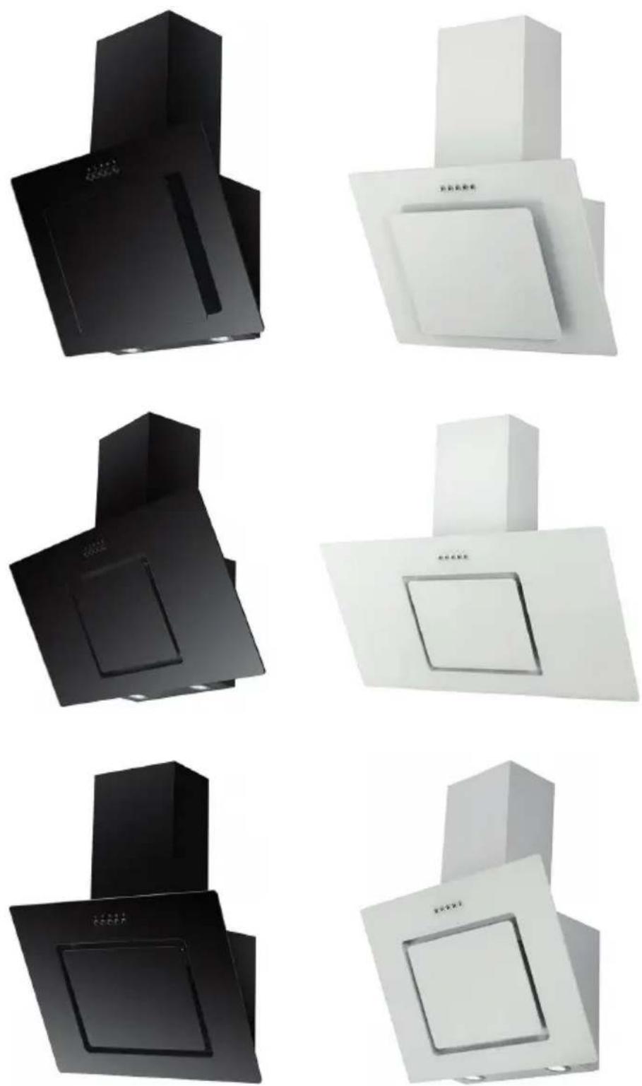
Respekta
Mod. No.:
CH 21060 SBZ
CH 21060 WBZCH 22010/90 SBZ
CH 22010/90 WBZ
CH 22010 SBZ CH 22010 WBZ
Inhalt
1 : ALLGEMEINE INFORMATIONEN......de-3
5: INSTALLATION de-19
text_image
0# # # #
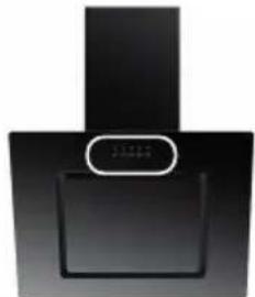
CH 21060 SBZ
natural_image
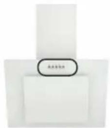
Abstract black geometric shape with a white circular annotation (no text or symbols)CH 21060 WBZ
text_image
日本語書館CH 22010/90 SBZ
natural_image
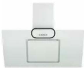
Black kitchen appliance with a vertical handle and a small circular button labeled 'LPG' (no visible text or symbols on the appliance itself)CH 22010/90 WBZ
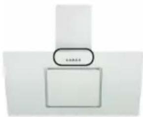
natural_image
Simple diagram of a T-shaped object with a rounded rectangle and a small oval label (no text or symbols)CH 22010 SBZ
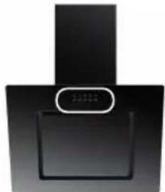
natural_image
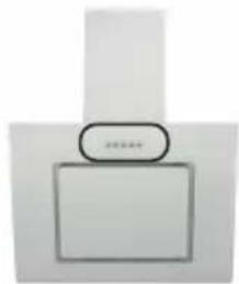
Black industrial kitchen fan with a white button and circular handle (no visible text or symbols)CH 22010 WBZ
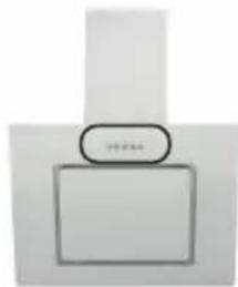
natural_image
Simple diagram of a rectangular box with a circular arrow pointing to it, no text or symbols present.Abb. 4.1
natural_image
Diagram of a pipe or channel with a brick wall and water flowing through it, labeled 'A)' (no text or symbols on the diagram itself)Abb. 5.1
natural_image
Diagram of a brick wall section with a pipe and foundation, labeled B) (no text or symbols within the diagram itself)Abb. 5.2
natural_image
Technical diagram of a pipe joint and adjacent wall with 2° angle标注 (no text or symbols)Abb. 5.3
text_image
Technical diagram showing a mechanical assembly with labeled components and directional arrows indicating motion or force.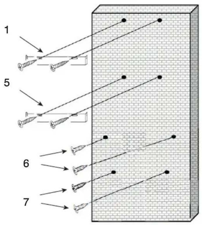
text_image
1 5 6 7Abb. 5.4
natural_image
Technical line drawing of a mechanical device with three views: top, front, and side (no text or symbols)Abb. 5.5
natural_image
Pure technical diagram of a rectangular panel with screwdriver and mounting holes, no text or symbols presentAbb. 5.9
natural_image
Close-up of a metallic industrial machine casing with two red circular annotations highlighting features (no readable text or symbols)Abb. 5.10
natural_image
Simple line drawing of a cabinet or storage unit with labeled section A (no text or symbols on the diagram itself)Abb. 5.11
natural_image
Simple line drawing of a simple roof structure with vertical supports and a horizontal beam (no text or symbols)Abb. 5.12
natural_image
Diagram of a 3D box setup with arrows indicating direction and components (no text or symbols)Abb. 5.13
natural_image
Simple line drawing of a mechanical assembly with two screws inserted into a rectangular frame (no text or symbols)Abb. 5.14
natural_image
Technical line drawing of a mechanical assembly with a component and red laser lines (no text or symbols)Abb. 5.15
natural_image
Diagram of a mounted device with red light rays and a small circular component, no text or symbols presentAbb. 5.16
natural_image
Interior view of a mechanical device with a cylindrical component and two red-circled features (no visible text or symbols)Abb. 5.17
natural_image
Diagram of a vertical cylindrical object mounted on a base with a protruding rod, showing internal flow or force direction (no text or symbols)Abb. 5.18
natural_image
3D rendering of a metallic heat exchanger with blue vertical lines and an arrow pointing to the top-right corner (no text or symbols)Abb. 5.19
6 : WARTUNG
1.1 Reading the manual......en-3
2 : GENERAL SAFETY RULES......en-7
2.1 Important warnings...... en-7
2.2 Environmental protection ...... en-9
3: TECHNICAL DATA AND CHARACTERISTICS......en-10
3.1 Technical data...... en-10
3.2 Dimensions ...... en-14
3.3 Circuit diagram...... en-14
4 : INSTRUCTIONS FOR USE......en-15
4.1 Preliminary recommendations...... en-15
4.2 Using the hood......en-16
5: INSTALLATION ...... en-19
5.1 List of accessories...... en-19
5.2 Preliminary operations ...... en-20
6: MAINTENANCE ...... en-30
6.1 Cleaning and care......en-30
6.2 Replacing the grease filter ...... en-31
6.3 Replacing the light bulbs......en-31
7: TROUBLESHOOTING ...... en-32
7.1 Problem solving...... en-32
1 : GENERAL INFORMATION
1.1 Reading the manual
1.1.1 Foreword
Dear customer, thank you for choosing an appliance from our range.
Your new appliance is designed to meet the requirements for home use. Please follow the instructions for use carefully since they describe the possible uses and operation of your new appliance.
This document applies to different appliance types, so it contains descriptions of functions that may not be present on your appliance.
The manufacturer declines all liability for personal injury or damage to property caused by incorrect or improper installation of the appliance.
The manufacturer reserves the right to update the various models with the changes necessary to comply with technical regulations in force.
Please get in touch with your dealer if you wish to request more information or lodge a complaint.
1.1.2 Manufacturer's data
1.1.3 Customer service
In case of technical queries concerning your appliance, contact your dealer's customer service department.
Before calling service, make sure you know:
- the appliance model name and identification details
1.1.4 Introduction and safety
Before installing and/or using the hood read the instructions in the manual carefully to gain familiarity with your new appliance.
Keep this document to hand so you can consult it whenever necessary and make sure you pass it on to any future owners of the appliance.
Read the safety messages in the introduction to this manual and pay attention to the safety notes: "Caution", "Warning" and "Danger" contained in the text.
 | This symbol means:NOTEThis symbol denotes useful advice and highlights correct procedures and behaviours. Acting in compliance with instructions tagged with this symbol will save time and trouble.The purpose of the symbol is to highlight certain methods or procedures to employ for correct use of the hood. |
 | This symbol means:WARNINGThis symbol is used to highlight an operation to be carried out with special care because it could result in damage to the structure of the hood or its components. |
 | This symbol means:CAUTIONThis symbol highlights safety information. Read the information carefully. Also make sure you have fully understood the causes of possible dangerous accidents. |
 | This symbol means:DANGERThis symbol is used to highlight a situation that is potentially dangerous for yourself or for others. Read the information carefully. Also make sure you have fully understood the causes of potentially serious or fatal accidents. |
 | This symbol means:DISPOSALThis symbol, shown on the product or on the pack, indicates that the product can be treated as normal household waste but must be consigned to a recycling centre for electrical and electronic equipment. Your participation in ensuring this product is disposed of correctly will help to protect the environment, and the health and well-being of your fellow citizens. Incorrect disposal of the appliance endangers the environment and health.More information on how to recycle this product can be obtained from local authorities, waste disposal regulations, or the point of sale where you purchased the product. |
1.1.5 Hood identification
text_image
G Respekta ZH I F Eff. Class B AFGI B C 220-240V~ 50 Hz TOTAL 70 W Motor 68 W 0.3 A Safety Class: I Dunstabzugshaube Mod.CH 21060 WBZ Cooker hood Type:KB60A-MW Hotte kg 9.77 Cappa aspirante 2x1 W LED Max. exhaust / recirculation 377.0 / 204.5 m3/h Charcoal Filter for Air circulation / Kohle Filter für Umluftbetrieb Mod: Filtre à charbon pour version de recyclage / Filtro a carbone per versione filtrante MIZ 6000 N L H Serien Nr. MZH202103010001 IMP. 2021-03 NEG-Novex Großhandelsgesellschaft für Elektro- und Haustechnik GmbH, Chenover Str. 5, D-67117 Limburgerhof www.respekta.info / WEEE-Reg-Nr.De91889217Fig. 1.1
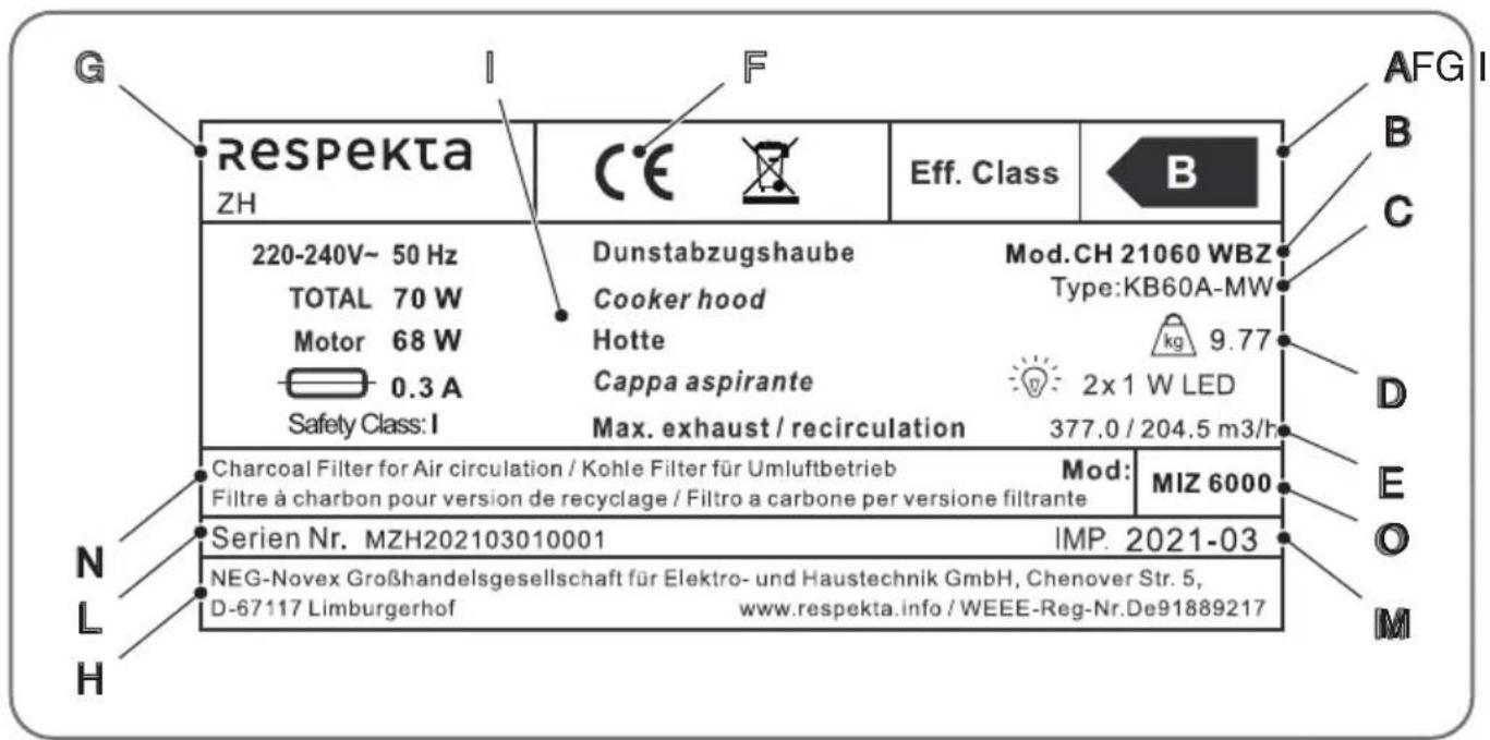
The hood nameplate bears the following information:
A - Energy class
B - Model
C - Technical type
D - Weight
E - Extraction
F - CE mark
G - Manufacturer
H - Manufacturer's data
I - Description
L - Serial number
M - Date of importation
N - Filter type
O - Filter model

NOTE: We recommend making a separate note of the appliance data and serial numbers to have a readily available record if needed.

NOTE: To optimize the response of our customer service and spare parts service organisation, always be prepared to quote the information given on the nameplate.
Location of nameplate
The appliance nameplate is located inside the frame.
CE declaration of conformity
The manufacturer of the appliances described herein, to which this declaration is referred, declares under its exclusive responsibility that these appliances comply with the fundamental safety, health and protection requirements of the relevant EC directives and that the associated test reports, and in particular the CE declaration of conformity duly issued by the manufacturer or its authorised representative, are available for inspection by the competent authorities and can be requested from the appliance dealer. The manufacturer also declares that any parts of the appliance or appliances described in this manual that may come into contact with fresh foods do not toxic substances.
1.1.6 Warranty conditions
The manufacturer does not take any responsibility for damage caused by the buyer.
This device has been manufactured and tested according to the latest methods. Irrespective of the seller's / dealer's statutory warranty obligation, the manufacturer provides a 6-month warranty for faultless material and faultless production for a period of 24 months from the date of purchase. The warranty expires in case of intervention by the buyer or by third parties. Damage caused by improper handling or operation, by incorrect installation or storage, by improper connection, improper installation, as well as by force majeure or other external influences, is not covered by the guarantee. We reserve the right to repair or replace defective parts or to exchange the device in case of complaints. Only if repair (s) or replacement of the device, the intended use by the manufacturer should not be finally achieved, the buyer can demand warranty within six months, calculated from the date of purchase, reduction of the purchase price or cancellation of the purchase contract.
Claims for damages, including consequential damages, unless they are based on intent or gross negligence excluded.
The warranty claim has to be proven by the buyer, by presenting the purchase receipt. The guarantee is valid within the Federal Republic of Germany.
2 : GENERAL SAFETY RULES
2.1 Important warnings

DANGER: Filters saturated with fat or oil can cause fires.

DANGER: There is a risk of fire if cleaning is not carried out in compliance with the instructions

CAUTION: Before making any connections make sure the mains voltage corresponds with the voltage shown on the label affixed to the inside of the appliance.

CAUTION: The extracted air must not be conveyed in a flue used to discharge fumes from appliances fired by gas or other fuels (not applicable to appliances that only discharge air into the room).

CAUTION: Connect the extracted air outlet from the hood to an expulsion duct of adequate inside diameter (no less than 120 mm).

CAUTION: Always provide adequate ventilation of the room when the hood and gas powered appliances are used simultaneously.

CAUTION: If the power cord is damaged it must be replaced by the manufacturer, by one of the manufacturer's service centres, or by a person having similar qualifications, in order to eliminate any possible risks.

CAUTION: Keep children away from the appliance. Children must be supervised to ensure they do not use the appliance improperly.

CAUTION: Use of the appliance by persons with physical, sensory, or psychological difficulties is permitted only under the supervision of carers.

CAUTION: To clean the interior of the appliance make sure it is first disconnected from the mains supply.

CAUTION: Flambé cooking under cooker hoods is not permitted under any circumstances.

CAUTION: If the appliance develops a fault, inform customer service. Do not attempt to repair the appliance on your own initiative.
 | WARNING: Always ensure all installation and adjustment operations are carried out by qualified personnel. |
 | WARNING: Once the hood has been removed from the pack check to ensure it is intact. If the product is damaged, do not use it and contact the RESPEKTA service network. |
 | WARNING: Comply with the regulations in force concerning discharge of air. |
 | WARNING: When the cooker hood and appliances powered by energy other than electricity are operating simultaneously, the negative pressure in the room must not exceed 4 Pa (4 x 10⁻⁵ bar). |
 | WARNING: Clean the exterior of the appliance only when it is switched off. |
 | WARNING: The appliance and its filters must be cleaned regularly to ensure correct operation. Refer to the “Maintenance” chapter. |
 | WARNING: Keep the room well ventilated when using the appliance with a gas hob. |
 | WARNING: The appliance air exhaust duct must be routed to the outside of the building in a separate passage; do not exhaust the air through other ducts or flues. |
 | WARNING: Before installing and using the appliance, make sure the voltage (V) and frequency (Hz) shown on the hood are identical to the voltage (V) and frequency (Hz) of the mains supply in your home. |
 | NOTE: Read the instructions carefully before installing and/or using the hood. |
 | NOTE: The appliances described in this document are not intended for commercial use. The appliances are designed for domestic use only. The warranty and its terms are reduced by 50% if the appliance is used in a commercial application. |
 | NOTE: In order to make a warranty claim be sure to submit the warranty card and sales receipt, otherwise the warranty will be void. |
2.2 Environmental protection
2.2.1 Packaging
The packaging materials are 100% recyclable. Comply with local regulations when disposing of the packaging materials.

WARNING: The packaging materials (plastic bags, polystyrene, etc.) are potentially dangerous for children. Keep the packaging materials out of reach of children.
2.2.2 Prescription

WARNING: Dispose of the old cooker hood in compliance with the law. Before disposing of the hood cut off the power cord to make it unusable. The hood must be disposed of by consigning it to an authorized recycling centre.
3 : TECHNICAL DATA AND CHARACTERISTICS
3.1 Technical data
3.1.1 Models CH 22010 SBZ - CH 22010 WBZ - CH 22010/90 SBZ
| Model no. CH 22010 SBZ CH 22010 WBZ | CH 22010/90 SBZ | |||
| Product identification / Brand | NEG respekta respekta respekta | |||
| Model type (standard, canopy, telescopic, chimney, etc.) | Chimney Chimney | Chimney | ||
| EU energy efficiency class B | B B | |||
| Annual energy consumption kW | Wh/year | 35.20 35.20 35.20 | ||
Characteristics
| Model no. CH 22010 SBZ CH 22010 WBZ | CH 22010/90 SBZ | |||
| Voltage / Frequency V/Hz | 220V~240V, 50Hz | 220V~240V, 51Hz | 220V~240V, 50Hz | |
| Installed power / main fuse (rating) | W / A 70 | W 70W 70W | ||
| Number of motors no. 1 1 1 | ||||
| Maximum motor power | W | 68W 68W 68W | ||
| Maximum extraction airflow | m3/h | 377 | 377 | 377 |
| Maximum recirculation airflow | m3/h | 204.5 204.5 204.5 | ||
| Max. Noise level | dB(A) | 62 | 62 | 62 |
| Length of power cord (including plug) | cm | 135cm | 135cm | 135cm |
| Plug type (Schuko CEE 7/7 / Euro type C (CEE 7/16) | Schuko CEE 7/7 | Schuko CEE 7/7 | Schuko CEE 7/7 | |
| Dimensions: Appliance (without chimney) | mm | 598x340x414 598x340x414 898x340x414 | ||
| Chimney max. extension | mm | from 400 to 780 | from 400 to 780 | from 400 to 780 |
| Appliance net weight | kg | 9.66 | 9.79 | 11.33 |
| Pack weight | kg | 1.53 | 1.53 | 1.89 |
| Gross weight | kg | 11.61 11.74 13.64 | ||
| Pack dimensions | mm | 648x462x392 648x462x392 948x462x392 | ||
| Duct connection size | mm | 150mm | 150mm | 150mm |
Equipment or accessories
| Model no. CH 22010 SBZ CH 22010 WBZ | CH 22010/90 SBZ | ||
| Switches on front / underside front front front front | |||
| Power switch: mechanical / electronic | mechanical mechanical mechanical | ||
| Light type / Power no. / W 2/1w 2/1w 2/1w | |||
| Duct connection nozzle on top / rear | Top Top Top | ||
| Assembly kit (screws, wall anchors, etc.) | cm 21.5x2.6 21.5x2.6 21.5x2.6 | ||
| Template for holes yes yes yes | |||
Grease filter specifications
| Model no. CH 22010 SBZ CH 22010 WBZ | CH 22010/90 SBZ | |||
| Grease filter: size / for hood mm / pc | 288*228 288*228 288*228 | |||
| Grease filter: dishwasher safe | no. | 1 | 1 | 1 |
| Grease filtering rate / Eff. Class | % / Eff. Class | D | D | D |
| Charcoal filter type: | NEG | MIZ 6000 | MIZ 6000 | MIZ 6000 |
| Number of charcoal filters per sales unit (-carton) | NEG 2 | 2 | 2 | |
| Number of Alu Grease filters installed on the appliance | pcs | 1 | 1 | 1 |
| Size of Alu Grease filter | mm | 288*228*9 | 288*228*9 | 288*228*9 |
3.1.2 Models CH 22010/90 WBZ - CH 21060 SBZ - CH 21060 WBZ
| Model no. | CH 22010/90 WBZ | CH 21060 SBZ CH | 21060 WBZ | |
| Product identification / Brand | NEG respekta respekta respekta | |||
| Model type (standard, canopy, telescopic, chimney, etc.) | Chimney Chimney | Chimney | ||
| EU energy efficiency class B | B B | |||
| Annual energy consumption kW | h/year | 35.20 35.20 35.20 | ||
Characteristics
| Model no. | CH 22010/90 WBZ | CH 21060 SBZ CH | 21060 WBZ | |
| Voltage / Frequency V/Hz | 220V~240V, 51Hz | 220V~240V, 50Hz | 220V~240V, 51Hz | |
| Installed power / main fuse (rating) | W / A 70 | W 70W 70W | ||
| Number of motors no. 1 1 1 | ||||
| Maximum motor power W 68W | 68W 68W | |||
| Maximum exhaust airflow | m3/h | 377 | 377 | 377 |
| Maximum recirculation airflow | m3/h | 204.5 204.5 204.5 | ||
| Max. Noise level | dB(A) | 62 | 62 | 62 |
| Length of power cord (including plug) | cm | 135cm | 135cm | 135cm |
| Plug type (Schuko CEE 7/7 / Euro type C (CEE 7/16) | Schuko CEE 7/7 | Schuko CEE 7/7 | Schuko CEE 7/7 | |
| Dimensions: Appliance (without chimney) | mm | 898x340x414 598x305x395 598x305x395 | ||
| Chimney max. extension | mm | from 400 to 780 | from 400 to 780 | from 400 to 780 |
| Appliance net weight | kg | 11.48 9.62 | 9.77 | |
| Pack weight | kg | 1.89 | 1.44 | 1.44 |
| Gross weight | kg | 13.79 11.48 11.63 | ||
| Pack dimensions | mm | 948x462x392 648x443x354 648x443x354 | ||
| Duct connection size | mm | 150mm | 150mm | 150mm |
Equipment or accessories
| Model no. | CH 22010/90 WBZ | CH 21060 SBZ CH | 21060 WBZ | |
| Switches on front / underside front front front front | ||||
| Power switch: mechanical / electronic | mechanical mechanical mechanical | |||
| Light type / Power no. / W 2/1w | 2/1w 2/1w | |||
| Duct connection nozzle on top / rear | Top Top Top | |||
| Assembly kit (screws, wall anchors, etc.) | cm 21.5x2.6 21.5x2.6 21.5x2.6 | |||
| Template for holes yes yes yes | ||||
Grease filter specifications
| Model no. | CH 22010/90 WBZ | CH 21060 SBZ CH | 21060 WBZ | |
| Grease filter: size / for hood mm / pc | / | 288*228 288*228 | 288*228 | |
| Grease filter: dishwasher safe no. 1 | 1 | 1 | ||
| Grease filtering rate / Eff. Class | % / Eff.Class | D | D | D |
| Charcoal filter type: | NEG | MIZ 6000 | MIZ 6000 | MIZ 6000 |
| Number of charcoal filters per sales unit (-carton) | NEG 2 | 2 | 2 | |
| Number of Alu Grease filters installed on the appliance | pcs | 1 | 1 | 1 |
| Size of Alu Grease filter | mm | 288*228*9 | 288*228*9 | 288*228*9 |
3.2 Dimensions
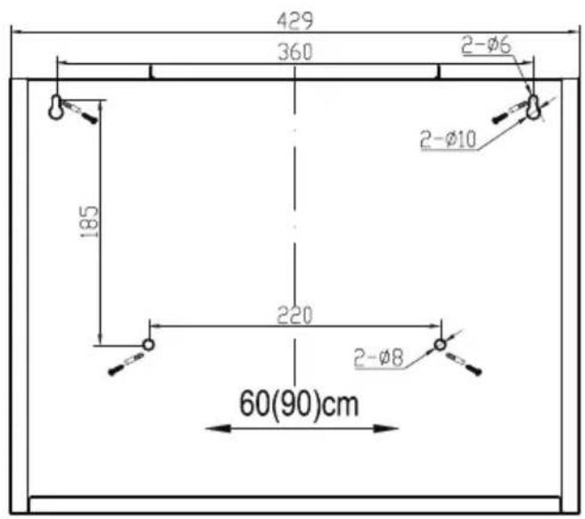
3.2.1 Positions and dimensions for installation
text_image
429 360 2-Ø6 185 220 2-Ø8 60(90)cmFig. 3.1
The positions and dimensions given are valid for the following models:
- CH 22010 SBZ; - CH 21060 WBZ;
- CH 22010 WBZ; - CH 22010/90 SBZ;
- CH 21060 SBZ; - CH 22010/90 WBZ.
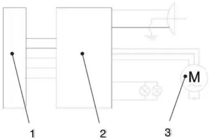
3.3 Circuit diagram
text_image
1 2 3 MFig. 3.2
1 - Switch
2 - Terminal block
3 - Electric motor
4 : INSTRUCTIONS FOR USE
4.1 Preliminary recommendations
 | DANGER: Do not prepare flambé dishes under the cooker hood. The flames could destroy the hood or cause a kitchen fire. |
 | DANGER: Never leave the pan unattended when frying because the hot fat may catch fire. |
 | CAUTION: The exhaust duct must not be made of or contain any flammable materials. |
 | WARNING: Disconnect the electrical power supply from the hood by unplugging the power cord or switching off the main circuit breaker before starting cleaning or maintenance work. |
 | WARNING: The air drawn in by the hood must not be exhausted through a stove flue pipe or the exhaust ducts of any other non-electrical appliances. |
 | WARNING: Regular maintenance will ensure good operation and optimal performance of your cooker hood. |
 | WARNING: Make sure the room is properly ventilated. |
 | WARNING: Clean surfaces regularly to remove any built-up dirt. |
 | WARNING: Clean or replace the filter regularly. |
 | WARNING: Make sure the hood has not been damaged in transport. |
 | WARNING: Installation, electrical connection and hood duct connections must be carried out by a qualified professional in compliance with the manufacturer's instructions and the regulations in force. |
4.2 Using the hood
4.2.1 Safety instructions for use
 | DANGER: No other operations producing flames are permitted. Open flames could damage the filter or other parts of the appliance or even cause a fire. |
 | CAUTION: If the hood is installed over a gas hob, do not switch on the gas rings without cooking pots. In the presence of open flames, parts of the appliance may be damaged by the resulting excessively high temperatures. |
 | CAUTION: Flambé cooking under the cooker hood is not permitted due to the risk of fire. The flames resulting from flambé cooking could ignite the fat accumulated in the filter. |
 | CAUTION: When frying or cooking with oil and fat under the hood supervise the work constantly to avoid the risk of fire. The risk of spontaneous combustion increases when the same cooking oil is reused repeatedly. |
 | WARNING: When the hood is in operation the grease filters must always be fitted, otherwise fat laden fumes will accumulate in the hood and in the air exhaust system. |
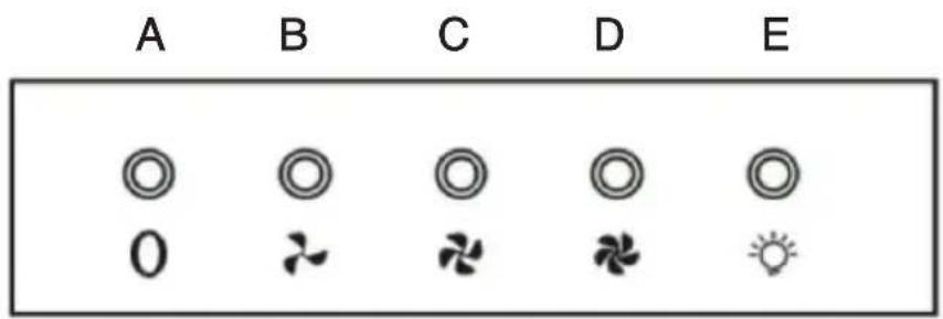
4.2.2 Buttons and switch functions
text_image
A B C D E 0CH 21060 SBZ
natural_image
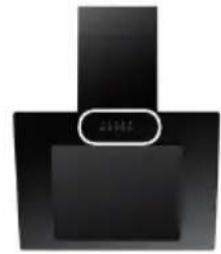
Abstract black geometric shape with a white circular annotation (no text or symbols)CH 22010/90 SBZ
natural_image
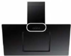
Black industrial kitchen appliance with a vertical handle and a circular button labeled '10000' (no visible text or symbols on the appliance itself)CH 22010 SBZ
natural_image
Black industrial kitchen appliance with a vertical handle and control panel (no visible text or symbols)CH 21060 WBZ
text_image
光效套装CH 22010/90 WBZ
natural_image
Simple diagram of a rectangular object with a circular label, no text or symbols presentCH 22010 WBZ
natural_image
Simple diagram of a rectangular box with a rounded top and a small oval label inside (no text or symbols)Fig. 4.1
A - Power ON/OFF
B - Speed 1
C - Speed 2
D - Speed 3
E - Light ON/OFF
4.2.3 Air extraction mode
The air is expelled to the exterior through the exhaust air duct. For this reason, the room must be equipped with an air exhaust duct leading to the outside of the building.

WARNING: If the hood operates in extraction mode and there are combustion systems in operation (e.g. a solid fuel stove), the room in which the appliance is installed must be supplied with a sufficient flow rate of fresh air at all times. Always seek the advice of a qualified technician.

WARNING: If a permanently installed air exhaust duct or flexible air extraction duct are not available, the hood must be operated in recirculation mode.
4.2.4 Recirculation mode
The air drawn in by the hood is filtered through a charcoal filter (also called an activated carbon filter) and then returned to the room. The charcoal filter removes cooking odours from the air. The filtered air is returned to the kitchen through the side or top air vents. If the hood is used in recirculation mode, simultaneous operation of a fireplace is of no concern in relation to air quality.

NOTE: Switch the appliance on a few minutes before you start cooking.
Leave the fan running for 5-10 minutes once you have finished cooking, on both the extraction version and the recirculation version. This precaution removes residual vapour and odours from the air in the kitchen.
- For improved performance of the hood, remove the vapour collector (if present).
- Adjust the fan speed in accordance with the quantity of fumes or vapour to be removed.
- Only switch the hood off about 5-10 minutes after you finish cooking.
- Replace the vapour collector (if present).
5 : INSTALLATION
5.1 List of accessories
| Item Image Quantity | ||
| Bottom chimney (A) and top chimney (B) | 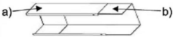 | 1 |
| Top chimney bracket | 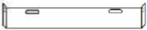 | 1 |
| Bottom chimney bracket and fixing flange | 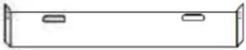 | 1 |
| 8mm dia. screw anchor | 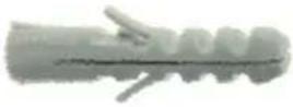 | 8 |
| 4x35mm countersunk screw | 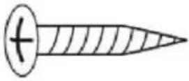 | 8 |
| 4x8mm countersunk screw (top and bottom chimney fixing) | 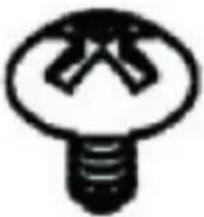 | 6 |
| V-Flap 1 | 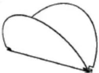 | |
| Air exhaust duct | 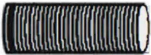 | 1 |
5.2 Preliminary operations
5.2.1 Safety instructions for installation

WARNING: Install the appliances only in a suitable location.

WARNING: Check the robustness and load-bearing capacity of the wall/ceiling.

WARNING: Check the paths followed by power cables etc. in the walls or ceiling to ensure you do not drill into them.

WARNING: Check the condition and load capacity of the electrical system.

WARNING: The appliance must be installed by a specialised technician.
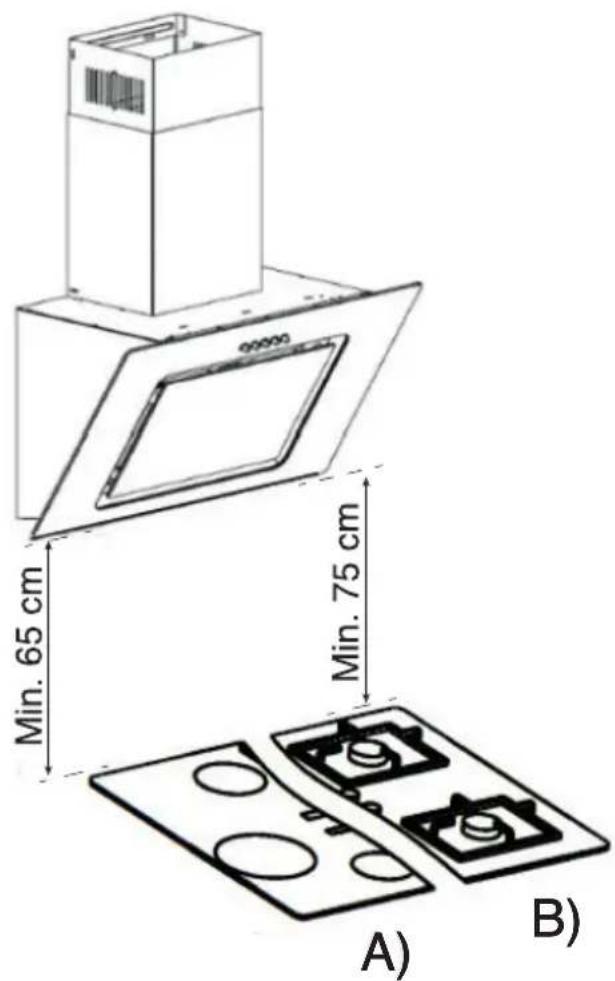
When installing the hood, comply strictly with the minimum distances specified between the hob and the hood (refer to “Installation details”) and follow the numbering of the work steps and the supplementary instructions. Cooking vapours are extracted through an air exhaust duct attached to the connecting ring. The diameter of the air exhaust duct must match the diameter of the connecting ring. If a V-flap is used or supplied, make sure it can open and close freely once the exhaust duct has been fitted. The cooker hood can be equipped with top and rear extraction openings. The hood is factory supplied for extraction type operation. Extraction openings that are not required are equipped with a plastic cover. The cover can be easily removed by turning it counter-clockwise.
5.2.2 Installation details
Minimum distance from the lower edge of the hood cabinet:
Induction hobs
Gas hobs
65 cm
75 cm

WARNING: Do not connect the appliance to the mains until it has been installed correctly.
5.2.3 Use of the hood in the extraction version
If the cooker hood is factory equipped with a charcoal filter, the latter must be removed. The charcoal filter is used only when the extractor hood is used in recirculation mode.
5.2.4 Use of the hood in recirculation mode
To use the appliance as a recirculation hood, the activated carbon filter(s) must be fitted on the fan motor before using the hood. An activated carbon filter or filters are included with some models. Otherwise, you will need to purchase an activated carbon filter or filters from your cooker hoods supplier/dealer.
5.2.5 Electrical hook-up

WARNING: Before connecting the hood, make sure the voltage (V) shown on the nameplate is the same as the mains voltage available in your home.

WARNING: Do not install the appliance if the nameplate values do not match the available supply voltage. The nameplate is located inside the hood, behind the grease filter.
If the hood is equipped with a standard plug, insert the plug into an easily accessible standard power outlet.
5.2.6 Fitting the charcoal filter
The instructions for installing the charcoal filter are supplied in the charcoal filter pack. To install the charcoal filter, remove the grease filter(s), then install the charcoal filter in compliance with the assembly instructions, and refit the grease filter(s).
5.2.7 Air exhaust duct
The air exhaust duct is not supplied.
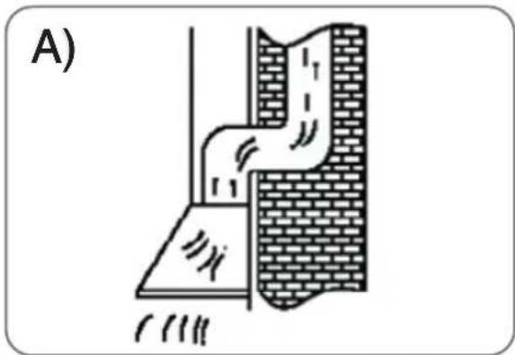
A - Air exhausted to outside the building
natural_image
Diagram of a pipe drainage system with brick walls and a sloped channel (no text or labels)Fig. 5.1
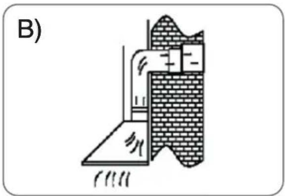
B - Air outlet via an air duct
natural_image
Diagram of a brick wall section with a sloped slope and a pipe, labeled B) (no text or symbols on the diagram itself)Fig. 5.2
The exhaust duct should be as short and straight as possible.
To avoid noisy operation or reduced air extraction capacity, the air exhaust duct must be at least 120 mm in diameter.
Use / make wide radius bends. Tight radius bends reduce the hood extraction capacity.
Use only smooth ducts or flexible ducts in non-flammable material for the exhaust air duct.
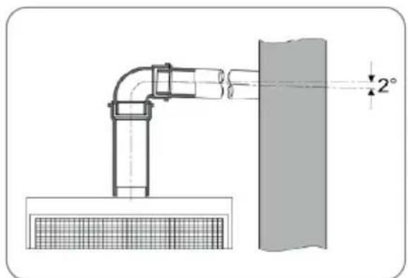
If the exhaust air duct follows a horizontal path, maintain a minimum downward slope of 1 cm per metre or 2° inclination angle towards the outside. Otherwise, condensate could trickle back into the cooker hood motor.
natural_image
Technical diagram of a pipe joint and adjacent wall section with 2° angle标注 (no text or symbols)Fig. 5.3
If the exhaust air is routed to an exhaust air flue, the end of the inlet fitting must be oriented in the direction of the airflow.
If the exhaust air duct is installed through rooms at low temperature, on wall brackets, etc., a significant temperature drop may occur in the single sections of tubing, with sweating or condensate production. For this reason, the air exhaust duct must be insulated.
In some cases a condensate trap (available from the main construction materials suppliers) should be installed in addition to adequate insulation.
5.2.8 Overview of installation components
text_image
Technical diagram showing a mechanical assembly with labeled components and directional arrows indicating motion or force.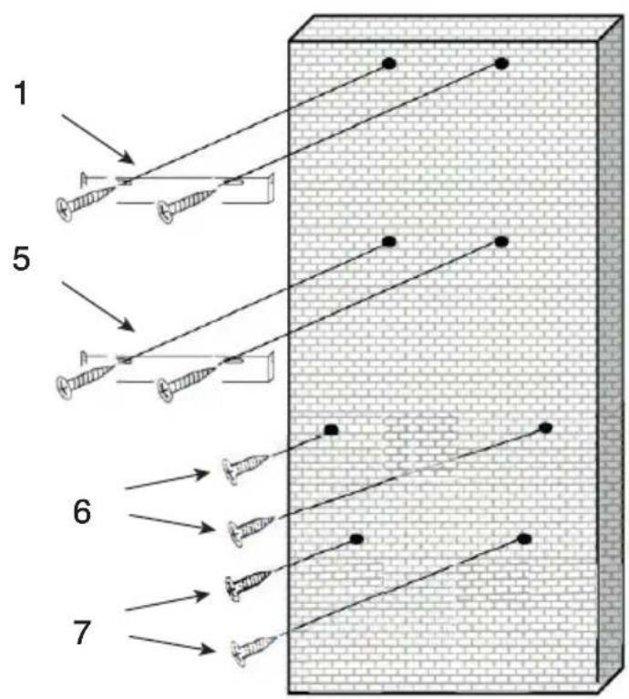
text_image
1 5 6 7Fig. 5.4
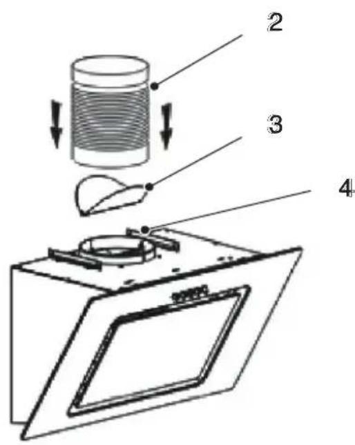
1 - Top chimney mounting bracket
2 - Extraction duct
3 - V-flap
4 - Bottom chimney bracket and fixing flange
5 - Chimney fixing flange
6 - Hood fixing screws
7 - Safety screws
Before installing the hood, switch off the main power switch to disconnect power from the socket from which the hood is powered.

CAUTION: Before installing the hood, fit the V-flap as described below.
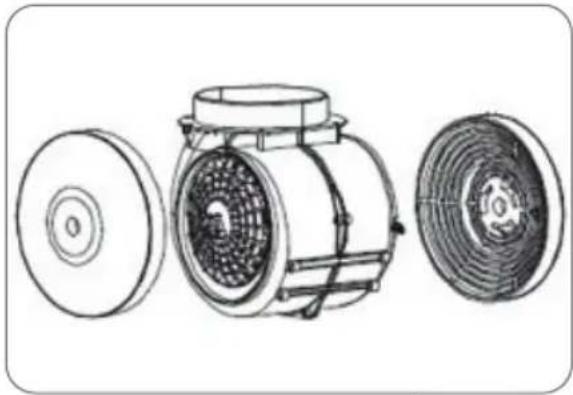
Fitting the activated carbon filter
Fit the charcoal filters (C) before fitting the grease filter.
natural_image
Technical line drawing of a mechanical device with three views: top, front, and side (no text or symbols)Fig. 5.5
Fitting the V-flap
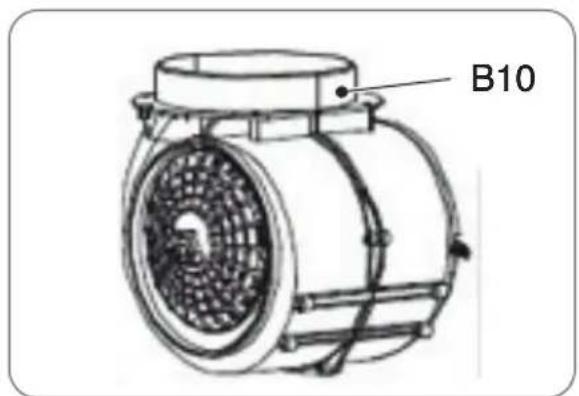
If the hood is not equipped with a preinstalled V-flap (B10), the two flaps must be fitted in the V-flap housing. The figures showing how to fit the V-flap are purely guideline because the procedure may vary according to the model and configuration.
text_image
B10Fig. 5.6
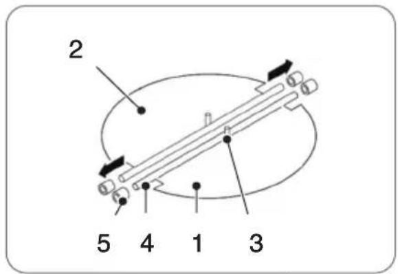
Fitting the V-flap:
1 - Fit the two flaps (1) in the housing (B10);
2 - Orient pin (3) so it is facing upwards;
3 - Insert spindle (4) into holes (5) in housing (B10);
4 - Repeat the same steps for the other flap (2).
text_image
2 5 4 1 3Fig. 5.7
5.2.9 Fitting the hood
Installation of the mechanical hood is different from installation of the Sensor Touch hood.

CAUTION: The cooker hood must be at least 65 cm from an induction hob (A) and at least 75 cm from a gas hob (B).
text_image
Min. 65 cm Min. 75 cm A) B)Fig. 5.8
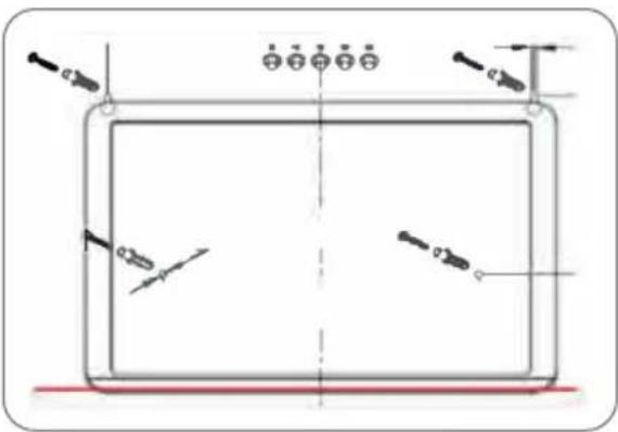
Take a pencil and draw a horizontal line on the wall in correspondence with the position of the lower edge of the hood.

CAUTION: Comply with the minimum distance shown in the "Installation details" section.
- Position the supplied template with the bottom edge on the line you have drawn and mark the hole positions.
- Use a suitable 8mm bit to drill 30mm deep holes in the wall in each of the 4 positions marked. As a precaution, check the diameter of the screw anchors.
- Insert screw anchors into each of the 4 holes.
- Screw a 4x35 mm countersunk screw into the two upper anchors.
text_image
Technical diagram showing a rectangular panel with four screwdriver positions and dimension annotationsFig. 5.9

CAUTION: The screw heads should protrude 3 - 5mm from the wall anchors in order to allow the hood to be suspended.
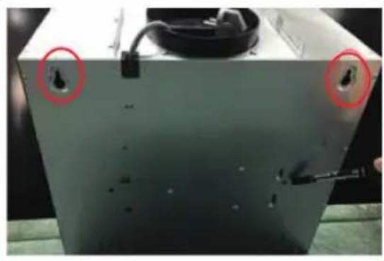
- Suspend the hood from the two screws in the wall using the two slots on the rear of the appliance.
- Fit the bottom chimney bracket on the top of the bottom chimney with two 8mm countersunk screws.
- Fit the bottom chimney section to the hood.
- Force the top chimney into the bottom chimney section from above.
natural_image
Close-up of a metallic industrial machine casing with two red-circled features, no visible text or symbols.Fig. 5.10
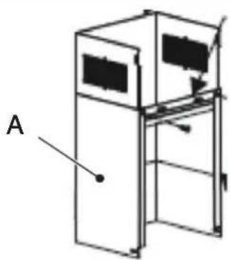
- Mount the support plate on the top of the chimney (A) with two 4x8mm countersunk screws.
- Position the assembled chimney sections on the hood.
natural_image
Simple line drawing of a two-tiered storage unit with labeled component A (no text or symbols beyond label)Fig. 5.11
- Press the base of the chimney firmly against the wall and use a pencil to mark the two hole positions through the holes in the chimney mounting plate
- Remove the exhaust duct from the hood.
- Drill two 40 mm deep holes in the wall in the marked points using a suitable 8mm drill bit.
- Force the top chimney into the bottom chimney section from above.
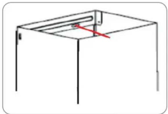
natural_image
Simple line drawing of a simple roof structure with vertical supports and a horizontal beam (no text or symbols)Fig. 5.12
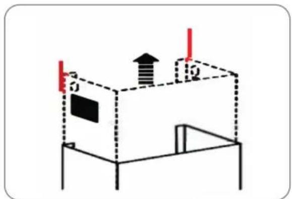
- Extend the chimney vertically up to the ceiling and draw lines at the sides.
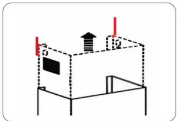
natural_image
Diagram of a 3D box setup with labeled dimensions and directional arrows (no text or symbols)Fig. 5.13
- Keep the top chimney mounting bracket (internal) in the centre of the ceiling between the marks (5.13). Mark the outline of the slots in the anchor bracket.
- Use a suitable 8mm drill bit to drill two 40mm deep holes in correspondence with the marks and insert two screw anchors.
- Fix the internal chimney mounting bracket to the ceiling using two 4x35mm countersunk screws.
- Position the two assembled chimney sections on the hood.
- Slide the internal chimney section fully down.
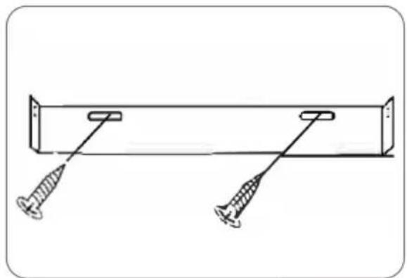
natural_image
Simple line drawing of a mechanical assembly with two screws and a rectangular frame (no text or symbols)Fig. 5.14
- Fix the bottom chimney mounting plate, (5.12) to the wall with two 4x35mm countersunk screws
- Fix the base of the bottom chimney with two 4x8mm countersunk screws on the sides of the hood.

natural_image
Technical diagram of a mechanical assembly with a component and red laser lines (no text or symbols)Fig. 5.15
- Secure the mounting bracket with two 4x8mm countersunk screws.
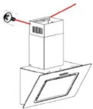
natural_image
Technical line drawing of a mechanical assembly with red laser lines and a magnified inset showing a component (no text or symbols)Fig. 5.16
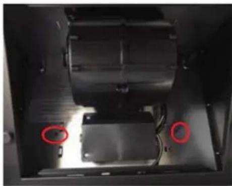
- Lift the front of the hood, remove the grease filter and secure the hood from the interior using two 4x35mm countersunk screws through the 2 holes in the hood rear panel.
- Fit the charcoal filters at the sides of the motor.
natural_image
Interior view of a mechanical device with a cylindrical component and two red-circled points of interest, no visible text or symbols.Fig. 5.17
5.2.10 Installation of the hood for air extraction type operation
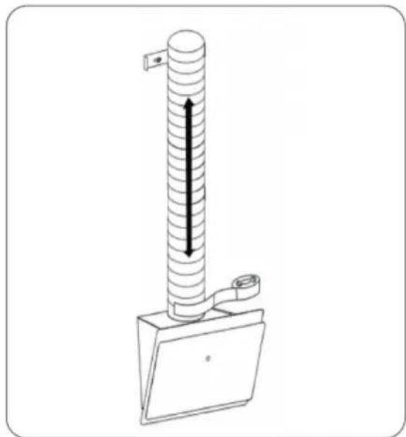
The wall opening must be sized for a 150mm diameter exhaust air duct. (Make a hole of approximately 155mm in diameter).
To install the hood in extraction mode, fit it as described in the previous section: "Mounting the hood", without fitting the charcoal filters.
Proceed as follows during the installation work:
1 - Remove the external and internal chimneys;
2 - Fit the exhaust duct;
3 - Refit the external and internal chimneys;
natural_image
Diagram of a vertical cylindrical device with a mounted sensor or gauge, showing internal flow direction (no text or symbols)Fig. 5.18
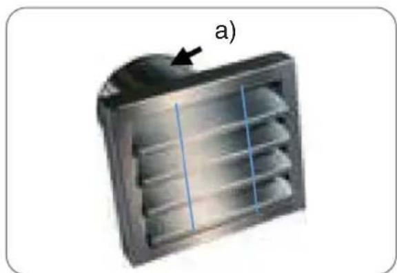
For final installation of the hood in extraction mode, an air outlet grille will be required with a 150mm fitting (a) for connection to the air exhaust duct. The grille is not supplied with the hood.
natural_image
3D rendering of a metallic heat exchanger or vent with internal flow lines and a black arrow pointing to the outlet (no text or symbols)Fig. 5.19
6 : MAINTENANCE
6.1 Cleaning and care
Before carrying out any installation, maintenance, or cleaning tasks, disconnect the hood from the electrical supply using one of these methods:
- Unplug the appliance power cord.
- Disconnect the electricity supply at the main circuit breaker.

DANGER: Failure to comply with the maintenance and cleaning instructions can cause a risk of fire due to the accumulation of cooking fat.

DANGER: The grease filters of your appliance must be cleaned or replaced at regular intervals. Filters saturated with grease can easily catch fire and may also give off odours.

WARNING: Do not use a steam cleaner to clean the cooker hood.

WARNING: Do not use detergents containing alcohol to clean appliances with a matt black finish. These types of detergents can cause discolouration.

WARNING: Grease filters clogged with particles of dirt can seriously impair operation of the appliance.

WARNING: When cleaning the controls area, take care to prevent water from penetrating into electrical and electronic parts.
Special information for appliances with stainless steel panels
Clean using a commercial non-abrasive detergent for stainless steel.
We recommend treating with a stainless steel coating product to prevent the surfaces from accumulating dirt rapidly.

WARNING: Never use detergents for stainless steel in the area of the controls.

WARNING: When cleaning the metal grease filters take care not to damage the mesh. Frequent cleaning or use of aggressive detergents can cause colour changes of the metal surface. Such changes do not affect operation of the filter and shall not be accepted as a motive for warranty claims.
6.2 Replacing the grease filter
The grease filters must be replaced periodically.
Metal grease filters
Metal grease filters do not require replacement when they are excessively saturated and are instead washed once a month by hand or in a dishwasher (60 °) (do not use corrosive rinse aids). Allow the filter to dry completely and refit it in the hood carefully.

WARNING: Do not use alkaline detergents for dishwashers (pH values above 7).
Charcoal filters
A - Conventional filters
Cannot be washed or regenerated. Charcoal filters must be replaced regularly, at least once every 3 months or sooner, depending on your cooking habits
B - Washable and regenerable charcoal filters
Must be washed in a dishwasher once a month, using a normal rinse aid and with an intensive rinse program (at the highest available temperature). Washable and regenerable charcoal filters absorb kitchen odours for a maximum of 3 years if cleaned monthly. After this period, the filter must be replaced with a new item.

WARNING: Washable and regenerable activated carbon filters must be washed separately to avoid the accumulation of food residues which can cause unpleasant odours. After washing, the washable and regenerable charcoal filter must be reactivated. This operation is performed by drying the clean filter in an oven for 10 minutes at 100 °C .
The washable / regenerable nature of your charcoal filter is stated on the pack. If no information is given on the pack, this means it contains a conventional non-washable charcoal filter.
Generic components
Whenever a grease filter or a charcoal filter is replaced or washed, clean all the exposed lower parts of the hood with a mild anti-grease solvent after removing the filter. For routine cleaning of the exterior parts of the hood use a soft cloth moistened with alcohol or a mild liquid detergent. Never use abrasive detergents.

WARNING: There is a risk of fire if the hood cleaning instructions and filter replacement or cleaning instructions are disregarded.
6.3 Replacing the light bulbs

WARNING: When changing a light bulb, make sure the new bulb is not of higher power than the original.
7 : TROUBLESHOOTING
7.1 Problem solving
| Error Possible cause | Solution | |
| Light working, motor not working | Blocked vent flap Remove obstruction | |
| Faulty capacitor Replace capacitor | ||
| Defective / jammed motor Replace motor | ||
| Motor emits odours Replace motor | ||
| Light not working, motor not working | In addition to the above causes, also the following are possible: | |
| Faulty light bulbs Replace bulbs | ||
| No power supply / appliance power cord not connected correctly | Check fuse / connect appliance power cord correctly | |
| Traces of oil | Leakage from V-flap Seal V-flap | |
| Leakage from joint between chimney and hood cabinet | Seal the joint with suitable means | |
| Hood vibration | An edge of the V-flap is damaged and is causing vibration | Replace the complete V-flap |
| Motor is not securely mounted Mount the motor correctly | ||
| Cabinet is not securely mounted Mount cabinet securely | ||
| Insufficient air extraction | Distance between hood and hob is excessive | Lower position of hood |
| Excessive air flow from an open door or window | Close doors and windows | |
| Device is unstable | Mounting bracket not securely fixed Tighten mounting bracket fixing screws | |
| Fixing screws not tightened Tighten fixing screws | ||
7.1.1 Motor fault
Check:
- that the plug is correctly inserted into the power outlet;
- that the main power switch is on.
7.1.2 Insufficient hood extraction capacity and noisy operation
Check:
- that the exhaust duct dimensions are adequate for the application;
- that the exhaust duct is not blocked or obstructed;
- that the cross section of the air duct (from hood to flue) is 150 mm. A smaller diameter air duct may impair motor performance;
- if the flue chimney is equipped with a mosquito screen, the air flow rate may be reduced; in this case, remove the screen;
- if the flue chimney cowl has fixed and steeply angled vanes, it should be removed;
- if the air flow is obstructed, equip the flue chimney with a cowl having mobile vanes;
- make sure the filters are clean;
- make sure the filters are less than six months old, otherwise they must be replaced.
7.1.3 Lighting fault
Check:
- the main switch is functioning correctly.