CH2060WBM - Range hood Respekta - Free user manual and instructions
Find the device manual for free CH2060WBM Respekta in PDF.


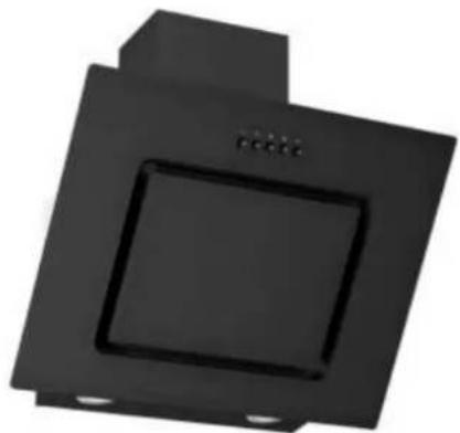
| Product Type | Inclined Cooker Hood |
| Brand | Respekta |
| Model | CH2060WBM |
| Width | 600 mm |
| Installation Type | Wall-mounted |
| Operating Modes | Recirculation and Exhaust Air |
| Duct Diameter | 150 mm |
| Filter Type | Grease filter (metal) and optional carbon filter |
| Number of Carbon Filters | 2 (mounted on motor sides) |
| Minimum Distance from Hob | Refer to user manual (typically 65 cm for electric, 75 cm for gas) |
| Power Supply | 220–240 V, 50 Hz |
| Control Type | Push buttons (assumed) |
| Weight (approx.) | 15 kg |
| Included Accessories | V-Flap, exhaust pipe, upper and lower chimney sections, mounting bracket, stabilizer bar, screws (ST4×40mm, ST4×30mm, ST4×8mm), wall plugs (φ8), ribbon |
| Chimney Type | Telescopic (upper and lower sections) |
| Safety Feature | Anti-backflow V-Flap |
| Maintenance | Clean grease filter regularly; replace carbon filter when saturated |
| Installation Difficulty | Requires professional installation (electrical connection) |
| Warranty | Refer to manufacturer documentation |
Frequently Asked Questions - CH2060WBM Respekta
User questions about CH2060WBM Respekta
0 question about this device. Answer the ones you know or ask your own.
Ask a new question about this device
Download the instructions for your Range hood in PDF format for free! Find your manual CH2060WBM - Respekta and take your electronic device back in hand. On this page are published all the documents necessary for the use of your device. CH2060WBM by Respekta.
USER MANUAL CH2060WBM Respekta
natural_image
Simple illustration of an adjustable wrench inside a circle (no text or symbols)respekta®
D
Montageanleitung
Installation Instructions
Inclined Cooker hoods
natural_image
Two black square electronic components with a central square and three small circular indicators (no text or symbols visible)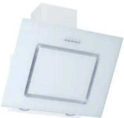
natural_image
White square electronic device with a circular recess, no visible text or symbols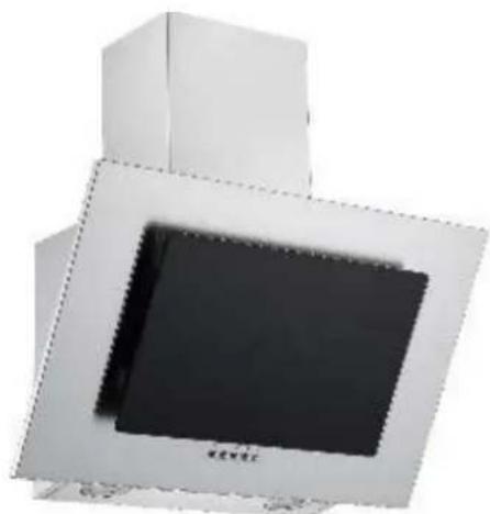
natural_image
Exterior view of a modern office building (no signage)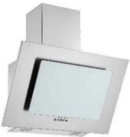
natural_image
Exterior view of a modern office building (no signage)Mod. No.:
CH 22010 SB
CH 22010-90 SB
CH 22010 WB
CH 22010-90 WB
CH 2060 SBM
CH 2060 WBM
SY-103E19U1-P1-C13-L122-600-900
SY-103E19A1-P1-C13-L122-600
natural_image
Close-up of a mechanical component with two red-circled features, no visible text or symbols| Accessory List | ||
| Item Picture Number | ||
| Lower chimney a) and upper chimney b) | a)-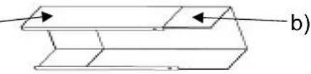 | 1 |
| Upper chimney bracket | 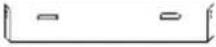 | 1 |
| Lower chimney stabilizer- and fixing bar | 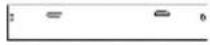 | 1 |
| Wall plug φ8 | 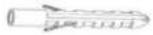 | 8 |
| Screw ST4×40mm (2 for upper chimney mounting bracket, 2 for lower cimney mounting plate) | 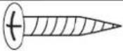 | 4 |
| Screw ST4×30mm (2 pcs for hood hanging, 2 pcs for hood locking) | 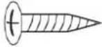 | 4 |
| ST4*8 screw (Upper- and lower Chimney fixing) | [BYZ7] | 6 |
| V-Flap | 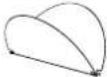 | 1 |
| Air exhaust pipe | 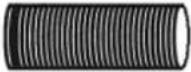 | 1 |
| Ribbon-8×550mm. |  | 1 |
General installation overview:
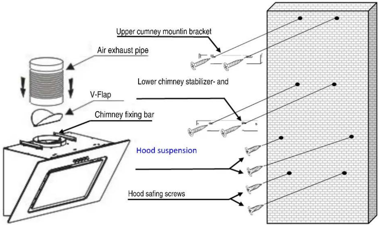
*The screws installed should leave for 3-5mm out of the wall to hang the hood on them
| Content: | Page |
| Mounting the V-Flap 2 | |
| Installation of the hood for recirculation mode | 2 - 3 |
| Mounting the hood for exhaust air operation | 4 |
Before beginning, make sure the power supply is secure. This must be set up by a specialist.
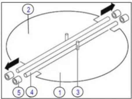
Attention! Before installing the hood, insert the V-Flaps as described below:
If the valve flaps are not factory-mounted:
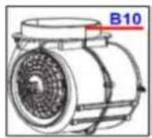
- First install half part 1 in connection nozzle B10
- Pins 3 must be in upwards position.
- Insert the axle 4 into the holes 5 on the nozzle B10.
- Repeat all operations for mounting the half part 2.
- Using pencil, draw a horizontal line at the height on the wall on which the hood bottom edge should lie. (It is best to use a water level) Attention! Observe minimum distance according to chapter 11.1 of the operating instructions.
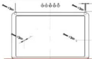
- Hold the supplied drill template with the bottom edge on the drawn pencil line against the wall and mark the four drill holes. (Fig. a)
- Drill a 30mm deep hole in the wall with an 8mm masonry drill at the 4 pencil marks. For safety, check the diameter of the plugs with a caliper gauge.
- Place one plug into each of the 4 holes.
- Screw a ST4 × 30mm screw into the two upper dowels (Fig. a) Attention! The screw heads must protrude 3 - 5 mm out of the dowels so that the hood can be hanged on them. (maybe readjust)
- Hang the hood with the two eyelets on its back (Fig. b) by the two screws on the wall.
- Mount the stabilizer- and mounting plate at the top of the lower flue with two ST4 * 8mm screws (Fig. c)
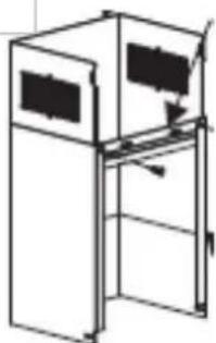
- Place the lower chimney shaft on the hood.
- Firmly press the chimney shaft against the wall and mark with pencil the two drill holes through the holes in the chimney stabilize- and mounting plate. (Fig. d)
-
Remove the chimney from the hood.
-
Drill two 40mm deep holes into the wall at the marked locations using an 8mm masonry drill.
-
Push the upper (inner) chimney shaft from above into the lower (outer) chimney shaft.
-
Place the nested chimneys on the hood.
Fig. a)
natural_image
Exterior view of a metallic industrial machine with mounting holes and internal components (no visible text or symbols)Fig. c)
natural_image
Line drawing of a double-door refrigerator with a side shelf and door, no text or symbols presentFig. d)
natural_image
Simple line drawing of a 3D rectangular box with internal structure and two red arrows indicating direction (no text or symbols)-
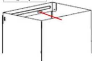
Pull the inner chimney shaft straight up to the ceiling and place one marking on the sides of the shaft. (Fig. e)
-
Remove the chimneys from the hood.
-
Hold the upper (inner) chimney mounting bracket (Fig. f) at the top center of the ceiling between the drawn marks (Fig. e) and mark the drilled holes with the two holes (Fig. f) in the mounting bracket a pencil.
-
Using an 8mm masonry drill, drill two 40mm deep holes at the pencil markers and place two plugs.
-
Fix the inner chimney mounting bracket (Fig. f) to the wall with two ST4 × 40mm screws at the top of the ceiling.
-
Place the two nested chimneys on the hood.
-
Slide the inner chimney shaft all the way down.
-
Attach the lower chimney stabilize- and mounting plate (Fig.d) to the wall with two ST4 x 40mm screws.
-
Fix the lower chimney shaft with two ST4 * 8mm screws on the sides of the hood (Fig. h) (Fig. g).
-
Pull the upper (inner) chimney shaft all the way up and secure it to the mounting bracket with two ST4 * 8mm screws. (Fig. h)
-
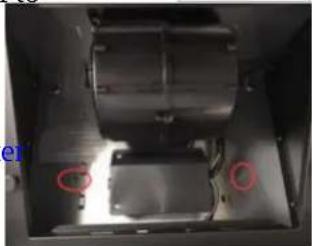
Lift the hoods on the front, remove the grease filter and secure the hood from the inside with two ST4 × 30mm screws through the 2 holes in the hood back panel to secure the hood. (Fig. i)
-
Mount the carbon filters on the sides of the motor. (See user's manual chapter "Using the carbon filters").
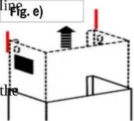
Fig. f)
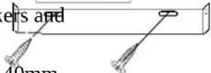
Fig. g)
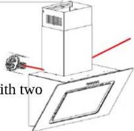
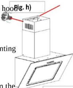
Fig. i)
natural_image
Interior view of a mechanical or electronic device with two circular annotations highlighting features (no readable text or symbols)Mounting the hood for exhaust air operation:
Attention! Be sure to observe chapter 11. "Installation" of user's manual.
The wall duct must be dimensioned for a 150 mm exhaust hose. (Drill hole about 155mm).
To mount the hood in exhaust air mode, mount it as described in the above chapter: "Mounting the hood for recirculation mode:", but without mounting the carbon filters.
Proceed as follows during assembly:
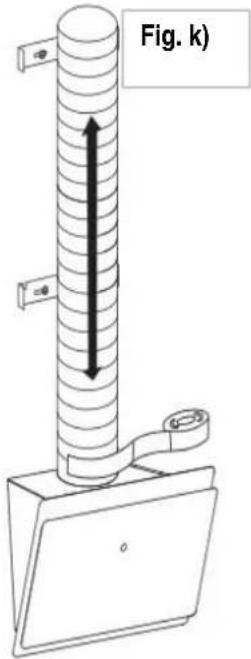
- Remove the outer and inner chimney.
- Mount the exhaust hose. (Fig. k)
- Replace the outer and inner chimney shaft.
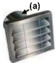
For the final assembly of the hood in exhaust air operation, you need an exhaust grille with a 150mm socket (a) for the connection of the exhaust air hose. This is not included in the delivery.
Illustrations serve partially just for illustration
Brand : Respekta
Model : CH2060WBM
Category : Range hood