
HmIP-eTRV-B1 - Thermostat SILVERCREST - Free user manual and instructions
Find the device manual for free HmIP-eTRV-B1 SILVERCREST in PDF.

| Product Type | Radiator Thermostat |
| Brand | SilverCrest |
| Model | HmIP-eTRV-B1 |
| Dimensions (H x W x D) | 86 x 55 x 55 mm |
| Weight | Approx. 120 g (including batteries) |
| Power Supply | 2 x LR03 (AAA) batteries, 1.5 V |
| Battery Life | Up to 2 years (typical use) |
| Radio Frequency | 868.0 - 868.6 MHz, 869.4 - 869.65 MHz |
| Max Radio Power | 10 mW |
| Valve Stroke | 4.5 mm (max) |
| Compatible Valves | M30 x 1.5 thread (most standard valves) |
| Temperature Range | 5 °C to 30 °C (set), 1 °C to 5 °C (frost protection) |
| Temperature Accuracy | ±0.5 °C (at 21 °C) |
| Control Type | Electronic, PID control |
| Display | LCD with symbols and temperature |
| Mounting | Directly on radiator valve (no adapter needed for M30) |
| Degree of Protection | IP20 |
| Operating Temperature | 0 °C to 50 °C |
| Humidity | 0% to 80% RH (non-condensing) |
| Maintenance | Wipe with dry cloth; do not use solvents or abrasives |
| Safety | Observe local regulations; do not use outdoors; children under 8 years must be supervised |
| Spare Parts & Repairability | Batteries user-replaceable; other repairs by qualified personnel only |
| General Information | Homematic IP compatible; use with Homematic IP central unit for full functionality |
Frequently Asked Questions - HmIP-eTRV-B1 SILVERCREST
User questions about HmIP-eTRV-B1 SILVERCREST
0 question about this device. Answer the ones you know or ask your own.
Ask a new question about this device
Download the instructions for your Thermostat in PDF format for free! Find your manual HmIP-eTRV-B1 - SILVERCREST and take your electronic device back in hand. On this page are published all the documents necessary for the use of your device. HmIP-eTRV-B1 by SILVERCREST.
USER MANUAL HmIP-eTRV-B1 SILVERCREST
Free download of the SilverCrest Smart Home appal


TARGA GMBH
Coasterweg 45
DE-39494 S
GERMANY
Operating instructions and safety instructions
IAN 309942_45
IAN 309942_45

Deutsch......2
English 40
V1.12
Inhalt
9.2.3 Stützring
natural_image
Symbol of a trash bin crossed with a diagonal line, no text or numbers present- Intended use....43
- Information on trademarks ....44
- Package contents....44
- Technical data....45
- Safety instructions ....46
- Copyright 49
- Overview of controls and display indicators 50
7.1 Device overview (see Figure 1)....50
7.2 Display overview (see Figure 2)....51
- General system information....52
- Initial use ....52
9.1 Teaching in....52
9.1.1 Teaching in the device onto the access point....53
9.1.2 Direct teaching in onto a SilverCrest Smart Home device (alternative).....54
9.2 Assembly 55
9.2.1 Installing the radiator thermostat ....57
9.2.2 Adapter for Danfoss RA....58
9.2.3 Support ring....59
9.3 Adaptation run....59
- Configuration menu....60
10.1 Automatic operation....61
10.2 Manual operation....62
10.3 Holiday mode 62
10.4 Operation lock....63
10.5 Programming a heating profile....64
10.6 Time and date 65
10.7 Offset temperature 66
11. Operation....66
12. Changing the batteries 67
13. Troubleshooting....68
13.1 Low battery capacity....68
13.2 Command not confirmed 68
13.3 Duty cycle....69
13.4 Error codes and flash sequences....70
14. Restoring the factory settings....73
15. Storing the device when not in use....74
16. General information on radio interference 74
17. Environmental and waste disposal information ....75
18. Marks of conformity....76
19. Notes on the guarantee and service....76
Congratulations!
By purchasing the SilverCrest Smart Home powered by Homematic IP HmIP-eTRV-B1 radiator thermostat, hereinafter referred to as 'radiator thermostat', you have opted for a high-quality product.
Familiarise yourself with the radiator thermostat before using it for the first time and read these operating instructions carefully. Observe the safety instructions in particular and only use the radiator thermostat in the manner described in these operating instructions and for the indicated fields of application.
Keep these operating instructions in a safe place. Hand over all documents in the event that you pass on the radiator thermostat to a third party.
SilverCrest Smart Home powered by Homematic IP gives you intelligent home control in just a few simple steps. All of the system's devices can be conveniently and individually configured via smartphone using the SilverCrest Smart Home app. To find out about the range of functions offered by the SilverCrest Smart Home system in combination with other SilverCrest Smart Home/ Homematic IP components, please refer to the Homematic IP user guide. All technical documents and updates are available at www.homematic-ip.com. The Homematic IP user guide can be found in the 'Service' section on the www.homematic-ip.com homepage.
1. Intended use
This device is an automatic, electric regulating and control device and is used to automatically regulate the temperature of a radiator. They may only be used for private purposes and are not for industrial or commercial use. The device should also not be used in tropical climates. The manufacturer will not be liable for any damage or faults arising as a result of unauthorised modification of the device. Only use the accessories specified by the manufacturer. Please observe the national regulations and/or laws in the respective country of use.
The SilverCrest Smart Home radiator thermostat can regulate the room temperature at set times and to suit requirements via a heating profile with individual heating phases. You can configure the radiator thermostat directly on the device and adapt it to your personal requirements. Alternatively, you can conveniently control the radiator thermostat in conjunction with the SilverCrest Smart Home access point via the free smartphone app.
The temperature is automatically decreased when airing in conjunction with a SilverCrest Smart Home window and door contact. The radiator thermostat fits on all conventional radiator valves and is easy to install – without draining heating water or intervention in the heating system. The additional Boost function makes it possible to quickly heat the radiator for a short period by opening the valve.
Please note that a two-pipe heating system with one flow and return line for each radiator is used to regulate the room temperature via the radiator thermostat. Use in single-pipe systems can result in significant deviations from the set temperature due to the fluctuations in the flow temperature.
Any other use, other than that described in these operating instructions, is deemed improper and will result in a loss of warranty and exclusion of liability.
2. Information on trademarks
Homematic IP is a brand of eQ-3 AG.
Apple ^® , iPhone ^® and iPad ^® are trademarks of Apple Inc., registered in the U.S. and other countries. App Store is a service mark of Apple Inc.
Google ^® and Android ^® are trademarks of Google Inc.
The SilverCrest brand is a registered trademark of Lidl Stiftung & Co. KG, D-74167 Neckarsulm, Germany.
Other names and products may be trademarks or registered trademarks of their respective owners.
3. Package contents
Unpack the device and all accessories. Remove all packaging materials and check all of the parts for completeness and signs of damage. If any parts are missing or damaged, please contact the manufacturer.
- Radiator thermostat
- Danfoss (RA) adapter
- Support ring
- M4 nut
- M4 x 12 mm cylinder head screw
- 2 x 1.5 V LR6/Mignon/AA batteries
-
Operating instructions
-
Technical data
| Device description: HmlP | -eTRV-B1 |
| Supply voltage: 2 x 1.5 V LR6/Mignon/A | A |
| Protection class: IP20 | |
| Operating temperature: 0 °C to 50 °C | 50 °C |
| Storage temperature: 0°C to 55°C | |
| Humidity: Maximum 85 percent relative humidity (non condensing) | - |
| Dimensions (W x H x D): 57 x 68 x 102 mm | |
| Weight: 185 g (including batteries) | |
| 1. Wireless frequency band: | 868.0–868.6 MHz |
| 2. Wireless frequency band: | 869.4–869.65 MHz |
| Maximum wireless transmitting capacity: | Frequency band 1: 10 dBmFrequency band 2: 10 dBm |
| Typical wireless free field range: max. 250 m (in ideal conditions) | |
| Duty cycle: <1% per hour (at 868.0–868.6 MHz)<10% per hour (at 869.4–869.65 MHz) | |
| Connection: M30 x 1.5 mm | |
| Actuating power: >80 N | |
| Valve stroke: 4.3 ± 0.3 mm | |
| Maximum stroke position: 14.3 ± 0.3 mm | |
| Maximum stroke position: 10.0 ± 0.3 mm |
The specifications and design are subject to change without notice.
5. Safety instructions
Before using the device for the first time, please read the following instructions carefully and observe all warnings, even if you are familiar with using electronic devices. Keep these operating instructions in a safe place for future reference. If you give the device away or sell it, please ensure that you also pass on this operating instructions. They are part of the product.
Symbols used and what they mean

DANGER! This icon, together with the word 'Danger', indicates an impending dangerous situation that, if not prevented, can lead to serious injuries or even death.

WARNING! This icon, with the word 'Warning', indicates important information for the safe operation of the device and user safety.

CAUTION! This icon, with the word 'Caution', indicates important information regarding safe operation and protecting against damage to property.

This icon indicates that further information on the topic is available.

DANGER! Batteries
Always insert batteries with the correct polarity. When doing so, observe the label in the battery compartment. Do not try to recharge the batteries and never throw them onto a fire.
Do not use different batteries (old and new, alkaline and carbon etc.) at the same time. Remove the batteries if you intend not to use the device for a longer period of time. There is a risk of explosion and leakage if the batteries are not used properly. Batteries are not a toy. In the event that the batteries are swallowed, seek immediate medical attention. Batteries must not be opened or deformed in any way because leaking chemicals can cause injury. If leaking chemicals come into contact with the skin or eyes, rinse/wash the area immediately with plenty of water and seek medical attention.

DANGER! Children and people with disabilities
Electrical devices must be kept out of the reach of children. In addition, people with restricted physical, sensory or mental abilities should only use electrical devices appropriately. Never leave children or people with disabilities unattended with electrical devices, unless they have been instructed on their use or will be supervised by a person responsible for their safety. Children should generally be supervised to ensure they do not play with this device. Small parts can be lethal if swallowed.
Keep the packaging film away from children.

There is a risk of suffocation!

WARNING! Maintenance/Repair/Cleaning
Do not open the device. It does not contain any parts that require maintenance by the user. In the event of a fault, have the device checked by a professional. Repair work is required if the device has been damaged, for example if the device housing is damaged, liquids or objects have got inside the device, or if the device does not work properly or has been dropped. If you notice any smoke, unusual noises or smells, immediately switch off the device by removing the batteries. In these cases, you must not continue to use the device until it has been checked by a specialist. All repair work should only be carried out by qualified specialists. Never open the housing of the device.
Clean the device with a soft, clean, dry, lint-free cloth. To remove stubborn marks, the cloth can be dampened slightly with lukewarm water. Do not use any cleaning agents that contain solvents as this may affect the plastic housing and labelling.
General safety instructions

WARNING! The device is only suitable for use in areas of residential use or similar. Only use the device in dry, dust-free environments. Do not expose to moisture, dripping or splashing water, vibrations, continuous sunlight, or other sources of heat, cold or mechanical loads.

WARNING! For safety and approval reasons, the unauthorised rebuilding and/or modification of the device is not permitted.

WARNING! Never continue using a damaged device.

WARNING! We shall assume no liability in the case of personal injury or damage to property caused by improper use or failure to observe the warnings. This will void any warranty. We shall assume no liability for any consequential damages!
6. Copyright
All contents of these operating instructions are subject to copyright law and are provided to the user solely as a source of information.
Any form of copying or reproduction of data and information without the express written permission of the author is prohibited. This also concerns commercial use of the content and data.
The text and illustrations correspond to the technical standards at the time of printing.
7. Overview of controls and display indicators
These operating instructions also have cover pages that can be unfolded. Unfold the cover pages so that you can always see the controls and display indicators.
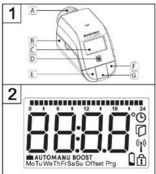
7.1 Device overview (see Figure 1)
A Cap nut
B Battery compartment
c Display
D System button (Teach-in button and LED)
E Minus button
F Plus button
G Menu/Boost button
7.2 Display overview (see Figure 2)
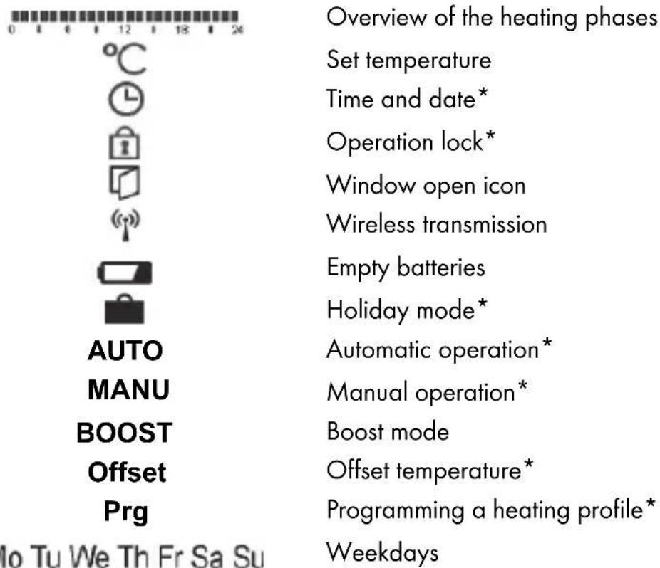
* see section '10. Configuration menu'
8. General system information
This device is a component of the SilverCrest Smart Home system and communicates via the Homematic IP radio protocol. All of the system's devices can be conveniently and individually configured via smartphone using the SilverCrest Smart Home app. Alternatively, it is also possible to use SilverCrest Smart Home devices via the Homematic CCU2/CCU3 central control unit or in connection with many other partner solutions. To find out about the range of functions offered by the system in combination with other components, please refer to the Homematic IP user guide. All technical documents and updates are available at:
www.homematic-ip.com
9. Initial use
9.1 Teaching in

Please read this section thoroughly before beginning the teach-in process.

Please also take note of the operating instructions for the corresponding devices (for example, access point, radiator thermostat, alarm sirens, and so on).
You can teach in the radiator thermostat onto either the SilverCrest Smart Home access point (HmIP-HAP-B1) or directly onto one or more SilverCrest Smart Home devices. When teaching in the device onto the access point, configuration is carried out using the SilverCrest Smart Home app; when teaching in directly, configuration is carried out on the device.
9.1.1 Teaching in the device onto the access point

Firstly, set up your access point via the SilverCrest Smart Home app to enable use of other SilverCrest Smart Home/Homematic IP devices in the system. More detailed information regarding this can be found in the operating instructions for the access point.

You can teach in the device both onto the access point and on the Homematic CCU2/CCU3 central control unit. You can find out more about this in the Homematic IP user guide (available in the 'Service' section at www.homematic-ip.com).
To enable the radiator thermostat to be integrated into your system and to allow it to be controlled via the SilverCrest Smart Home app, it must be taught in onto the access point.
To teach in the radiator thermostat, proceed as follows:
- Open the SilverCrest Smart Home app from your smartphone.
- Select the "Teach-in device" menu item.
- Remove the battery insulation tabs from the battery compartment (B) of the radiator thermostat. The teach-in mode is active for three minutes.

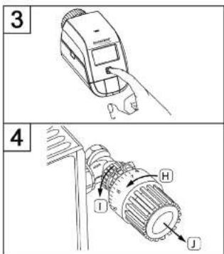
You can start the teach-in mode manually for a further three minutes by briefly pressing the System button (D) (see Figure 3).
• The device automatically appears in the SilverCrest Smart Home app.
- To confirm, enter the last four digits of the device number (SGTIN) into the app or scan the QR code. The device number can be found on the label in the package contents or on the device itself.
- Wait until the teach-in process is complete.
- To confirm successful completion of the teach-in process, the LED will turn green briefly and then go off again. The device is now ready for use.

The LED will turn red if the teachin process failed. Try it again. Please take particular care to ensure that the last four digits of the device number are entered correctly/the QR code is scanned correctly.
• In the app, give the device a name and assign it to a room.
9.1.2 Direct teaching in onto a SilverCrest Smart Home device (alternative)

You can teach in the SilverCrest Smart Home radiator thermostat - basic (HmIP-eTRV-B1) directly onto the SilverCrest Smart Home window and door contact with magnet (HmIP-SWDM-B2).

During the teach-in process, keep a minimum distance of 50 cm between the devices.

You can cancel the teach-in process by briefly pressing the System button (D) again. The device LED (D) will turn red to confirm this.
To teach in the radiator thermostat onto a different SilverCrest Smart Home/Homematic IP device, you must put both devices into teach-in mode. Proceed as follows:
- Remove the battery insulation tabs from the battery compartment (B) of the radiator thermostat. The radiator thermostat now performs an adaptation run.
- Following the completion of the adaptation run, press the System button (D) for at least four seconds to activate the teach-in mode (see Figure 3). The device LED (D) begins to flash orange. The teach-in mode is active for three minutes.
- Press the System button of the device to be taught in (for example, the SilverCrest Smart Home window and door contact with magnet) for at least four seconds to
54 - English
activate the teach-in mode. The device LED begins to flash orange. Further information regarding this can be found in the operating instructions for the respective device. The device LED flashes green to indicate that the teach-in process was successful. If the teach-in process was not successful, the device LED will turn red. Try it again.

The teach-in mode is automatically ended after three minutes if no teaching in takes place.

If you would like to add another device to the existing devices, you must first put the existing device into teach-in mode, then the new device.

If, for example, you would like to add another radiator thermostat to the existing devices, you must first teach in the new radiator thermostat onto the existing radiator thermostat. Then you can teach in the new radiator thermostat onto the existing door and window contact.

If you use several devices in a room, you should teach in all devices onto one another.
9.2 Assembly

Please read this section thoroughly before you begin installing the device.
The SilverCrest Smart Home radiator thermostat can be easily installed without draining the heating water or intervention in the heating system. No special tools are required and the heating does not need to be turned off.
The cap nut (A) mounted on the radiator thermostat is designed for universal use and does not require any accessories to fit all valves with M30 x 1.5 mm threads from major manufacturers such as
■ Heimeier
■ MNG
■ Junkers
■ Landis&Gyr (Duodyr)
■ Honeywell-Braukmann
■ Oventrop
■ Schlösser
■ Comap
■ Valf Sanayii
■ Mertik Maxitrol
■ Watts
■ Wingenroth (Wiroflex)
■ R.B.M
■ Tiemme
Jaga
Siemens
Idmar
The adapter included in the package contents also enables the device to be installed on radiator valves of the Danfoss RA type (see section '9.2.2 Adapter for Danfoss RA'.
9.2.1 Installing the radiator thermostat

Caution! Please consult a professional if there is noticeable damage to the existing thermostat, the valve or the heating pipes.
Dismantle the old thermostat head from your radiator valve.
- Turn the thermostat head counter-clockwise to the highest value (H) (see Figure 4). The thermostat head no longer presses against the valve spindle and is therefore easier to remove.
The thermostat head may be attached using various means:
- Cap nut: Unscrew the cap nut in the counter-clockwise direction (I). You can then remove the thermostat head (J).
- Snap-on fasteners: You can easily loosen thermostat heads that are attached in this manner by turning the fastener/cap nut slightly counter-clockwise (I). You can then remove the thermostat head (J).
- Clamp fittings: The thermostat head is held by a mounting ring, which is held together by a screw. Loosen this screw and remove the thermostat head from the valve (J).
- Screw connection with grub screws: Loosen the grub screw and remove the thermostat head (J).
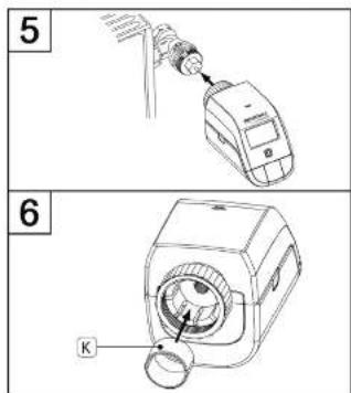
After dismantling the old thermostat head you can put the SilverCrest Smart Home radiator thermostat onto the radiator valve using the cap nut (A) (see Figure 5).
If necessary, use the included adapter for Danfoss RA valves (see section '9.2.2 Adapter for Danfoss RA') or the included support ring (see Section '9.2.3 Support ring').
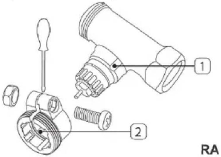
9.2.2 Adapter for Danfoss RA
The included adapter is required for installation on Danfoss RA valves.
The RA adapter was produced to achieve a better fit with pre-stressing. Use a screwdriver during installation if necessary and bend the adapter open slightly near the screw (see following figure).
The Danfoss valve bodies have lengthwise notches around them (1) that also ensure a better fit of the adapter after it has snapped into place.

During installation, make sure that the studs on the inside of the adapter (2) fit into with the notches (1) on the valve. Snap on the appropriate adapter for the valve completely.

WARNING! Be careful not to pinch your fingers between the two halves of the adapter.
After snapping the adapter onto the valve body, fasten it with the included screw and nut.
9.2.3 Support ring
The valves produced by some manufacturers have small diameters on the part of the valve that extends into the device, which results in a loose fit. In this case, the included support ring (K) should be inserted into the flange of the device prior to installation (see Figure 6).
9.3 Adaptation run

After the batteries are inserted, the motor initially retracts to facilitate the installation. 'InS' and the activity icon (n) are displayed during this process.
Once the radiator thermostat has been successfully installed, an adaptation run then needs to be performed to adjust it to the valve.
Do this by proceeding as follows:
- When 'AdA' appears on the display, press the Menu/Boost button (G) to start the adaptation run.
The radiator thermostat now performs an adaptation run. 'AdA' and the activity icon (N) are shown on the display. Operation is not possible during this process. Once the adaptation run is complete, the display switches to show its usual information.

If the adaptation run was initiated prior to installation or if an error message (F1, F2, F3) is displayed, press the Menu/Boost button (G) and the motor returns to the 'InS' position.
10. Configuration menu
If you use the radiator thermostat without an access point, you can select the following modes directly on the device after initial use via the configuration menu and make settings to adapt the device to your personal requirements.

The configuration menu can only be accessed if the radiator thermostat has not been registered at an access point yet.
Proceed as follows:
- Access the configuration menu by pressing and holding the Menu button (G).
- Select the desired icon using the Plus or Minus buttons (E + F) and briefly pressing the Menu button in order to make settings for the various menu items.

You can return to the previous level by pressing and holding the Menu button (G). If no buttons are pressed for more than one minute, the menu closes automatically without applying the set changes.
Display icons and indicators
| 10.1 | AUTO | Automatic mode |
| 10.2 | MANU | Manual mode |
| 10.3 | Holiday mode | |
| 10.4 | Operation loc | k |
| 10.5 | Prg | Programming a heating profile |
| 10.6 | Date and time | |
| 10.7 | Offset | Offset temperature |


If you teach in the device onto the access point, you can conveniently make settings using the free SilverCrest Smart Home app.
If you have already made settings in the configuration menu or have already taught in the device directly onto a different SilverCrest Smart
Home/Homematic IP device, you must first restore the factory settings of the device (see section '14. Restoring the factory settings') in order to teach in the radiator thermostat onto an access point or a Homematic CCU2/CCU3 central control unit.
10.1 Automatic operation

Automatic operation is only possible if the time has been programmed.
In automatic mode, the temperature is regulated according to the set heating profile. Manual changes are maintained until the next switching time. The set heating profile is then activated again. Proceed as follows to activate automatic operation:
- Open the configuration menu by pressing the Menu button (G) for approx. two seconds.
• Use the Plus or Minus buttons (E + F) to select the 'Auto' menu item. - Confirm with the Menu button.
The icon flashes twice briefly to confirm, and the device switches to automatic operation.
10.2 Manual operation
The temperature is regulated according to the set temperature using the buttons (E + F) during manual operation. The temperature is maintained until the next manual change is made. Proceed as follows to activate manual operation:
- Open the configuration menu by pressing the Menu button (G) for approx. two seconds.
• Use the Plus or Minus buttons (E + F) to select the 'Manu' menu item. - Confirm with the Menu button.
The icon flashes twice briefly to confirm, and the device switches to manual operation.
10.3 Holiday mode
Holiday mode can be used when a fixed temperature is to be maintained for a specific period (e.g. during a holiday or a party). Proceed as follows to set the holiday mode:
- Open the configuration menu by pressing the Menu button (G) for approx. two seconds.
- Use the Plus or Minus buttons (E + F) to select the 'Holiday 🔊' menu item and confirm with the Menu button.
- Use the Plus or Minus buttons to enter the ending time for the holiday mode and confirm with the Menu button.
- Use the Plus or Minus buttons to enter the ending date for the holiday mode and confirm with the Menu button.
62 - English
- Use the Plus or Minus buttons to enter the desired temperature while you will be away and confirm with the Menu button.
The icon flashes twice briefly to confirm, and the device switches to manual operation.
10.4 Operation lock
The operation of the device can be locked in order to prevent unwanted changes to settings, e.g. due to unintentional contact. Proceed as follows to activate or deactivate the operation lock:
- Open the configuration menu by pressing the Menu button (G) for approx. two seconds.
- Use the Plus or Minus buttons (E + F) to select the 'Operation lock 🔒' menu item.
- Confirm with the Menu button.
- Use the Plus or Minus buttons to select 'On' in order to activate the operation lock or 'Off' in order to deactivate the operation lock and confirm with the Menu button.
The selection flashes twice briefly to confirm, and the device switches back to the standard display.
The 'Lock' icon is shown on the display when the operation lock is activated.
Proceed as follows to deactivate the operation lock:
- Open the configuration menu by pressing the Menu button (G) for approx. two seconds.
- Confirm with the Menu button.
- Use the Plus or Minus buttons (E + F) to select 'Off' in order to deactivate the operation lock.
10.5 Programming a heating profile

It is useful to programme the time prior to programming a heating profile.
Under this menu item, you can create a heating profile with heating and reduced temperature phases that suit your individual requirements.
- Open the configuration menu by pressing the Menu button (G) for approx. two seconds.
- Use the Plus or Minus buttons (E + F) to select the 'Prg' menu item and confirm with the Menu button.
- Under 'DAY', use the Plus or Minus buttons to select individual days of the week, all workdays, the weekend or the entire week for your heating profile and confirm with the Menu button.
- Confirm the start time 00:00 with the Menu button.

Example of a 24-hour heating profile:
| 00:00 to 05:00 | 16 °C |
| to 08:00 | 24 °C |
| to 17:00 | 20 °C |
| to 22:00 | 22 °C |
| to 23:59 | 16 °C |
- Use the Plus or Minus buttons to select the desired temperature for the start time and confirm with the Menu button.
- The next time is indicated on the display. You can change this time using the Plus or Minus buttons. It is always set in five-minute increments.
- Use the Plus or Minus buttons to select the desired temperature for the next period of time and confirm with the Menu button.
- Repeat this process until temperatures are stored for the entire period from 0:00 to 23:59.
The time flashes twice briefly to confirm, and the device switches back to the standard display.
10.6 Time and date
Proceed as follows to set the date and time:
- Open the configuration menu by pressing the Menu button (G) for approx. two seconds.
- Use the Plus or Minus buttons (E + F) to select the 'Date/time' menu item.
- Confirm with the Menu button.
- Use the Plus or Minus buttons to select the year and confirm with the Menu button.
• Use the Plus or Minus buttons to select the month and confirm with the Menu button.
• Use the Plus or Minus buttons to select the day and confirm with the Menu button. - Use the Plus or Minus buttons to select the hours and confirm with the Menu button.
- Use the Plus or Minus buttons to select the minutes and confirm with the Menu button.
The time flashes twice briefly to confirm, and the device switches back to the standard display.
10.7 Offset temperature
Because the temperature is measured at the radiator thermostat, it may be warmer or colder elsewhere in the room. An offset temperature of ±3.5 ^ can be set to compensate for this. If, for example, a temperature of 18 ^ is measured rather than the set 20 ^ , an offset of -2.0 ^ should be set. An offset temperature of ±0.0 ^ is set factory. Proceed as follows to individually adjust the offset temperature:
- Open the configuration menu by pressing the Menu button (G) for approx. two seconds.
• Use the Plus or Minus buttons (E + F) to select the 'Offset' menu item. - Confirm with the Menu button.
- Use the Plus or Minus buttons to select the desired offset temperature and confirm with the Menu button.
The temperature flashes twice briefly to confirm, and the device switches back to the standard display.
11. Operation
After teaching in and installation, simple operating functions are available to you directly on the device.
- Temperature: Press the left (E) or right (F) button to manually change the temperature of the radiator. In automatic mode, the manually set temperature is maintained until the next switching time. The set heating profile is then activated again. In manual mode, the temperature is maintained until the next manual change is made.
- Boost function: Briefly press the Boost button (G) in order to activate the Boost function, which quickly heats the radiator for a short period by opening the valve (for 300 seconds). This immediately results in a comfortable feeling of warmth in the room.

If there are a number of linked thermostats in a room, any settings that are made (temperature, Boost function) are adopted by all of the other thermostats.
12. Changing the batteries
If the empty battery icon (☐) appears on the display or in the app, replace the old batteries with two new type LR6/Mignon/AA batteries. When doing so, observe the correct polarity of the batteries.
To insert new batteries in the radiator thermostat, proceed as follows:
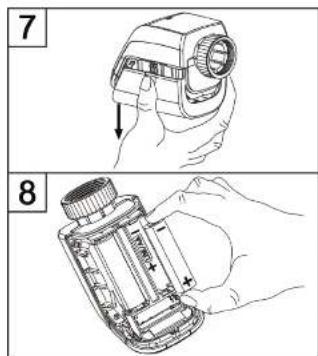
- Slide the battery compartment cover down to remove it (B) (see Figure 7).
- Remove the batteries.
- Insert two new 1.5 V LR6/Mignon/AA batteries into the battery compartment according to the polarity shown on the marking (see Figure 8).
- Close the battery compartment cover again.
- After the batteries have been inserted, take note of the flash sequences on the LED (see section '13.4 Error codes and flash sequences').
After the batteries have been inserted, the radiator thermostat first performs a self-test for about two seconds. Then initialisation is carried out. The LED turns orange and green to indicate test completion.

DANGER! If the batteries are not replaced properly, there is a risk of explosion. Only replace with the same batteries or batteries of the same type. Batteries must never be recharged. Do not throw batteries into a fire. Do not expose batteries to excessive heat. Do not short the batteries. There is a risk of explosion!
13. Troubleshooting
13.1 Low battery capacity
If the voltage allows, the radiator thermostat will also be operational when the battery capacity is low. Depending on the load, after a brief battery recovery period, the alarm signals may be transmitted again multiple times.
If the voltage fails again during transmission, the empty battery icon (☐) and the error code will be displayed on the device (see section '13.4 Error codes and flash sequences'). In this case, replace the empty batteries immediately with two new batteries of the same type in order to guarantee safe operation (see section '12. Changing the batteries").
13.2 Command not confirmed
If at least one receiver does not confirm a command, the LED will turn red at the end of the faulty transmission. The reason for faulty transmission may be due to radio interference (see section '16. General information on radio interference"). Possible causes of the faulty transmission are:
- Receiver batteries are dead
• The receiver cannot be reached
• The receiver cannot carry out the command (load failure, mechanical blockade etc.)
- The receiver is faulty.
13.3 Duty cycle
The duty cycle describes a legally regulated limit on a device's transmission time in the 868 MHz range. The aim of the regulation is to guarantee the functioning of all devices operating in the 868 MHz range. In the 868.0–868.6 MHz frequency range that we use, the maximum transmission time for any device is one per cent per hour (that is, 36 seconds an hour). When the one percent limit is reached, the devices are no longer able to transmit a signal until the time limit has passed. In accordance with this guideline, SilverCrest Smart Home powered by Homematic IP devices are developed and produced in full compliance with all relevant standards.
In standard mode, the duty cycle is generally not reached. However, in certain cases, it may be reached during initial use or installation of a system due to the increased, radio-intensive teach-in processes. If the duty cycle limit is exceeded, the device LED (D) will emit a long red light and the device may stop working temporarily. The device will then start working again after a short time (one hour maximum).
13.4 Error codes and flash sequences
| Flash sequence code/ Display information | Meaning Remed | y |
| F1 Valve actuation not | running smoothly | Check whether the tappet of the heating valve is jammed. |
| F2 Setting range too large | Check the mounting of the | radiator thermostat. |
| F3 Setting range too small | Check whether the tappet of the heating valve is jammed. | |
| No display | Batteries y em | Replace the batteries of the device (see Section '12. Changing the batteries"). |
| No display The batteries were inserted incorrectly. | Insert batteries correctly. Observe the correct polarity of the batteries. | |
Battery icon  battery voltage lo w battery voltage lo w | Replace the batteries of the device (see Section '12. Changing the batteries"). | |
Battery icon  and --- and --- | Valve emergency position reached | Replace the batteries of the device (see Section '12. Changing the batteries"). |
Antenna icor  flashes flashes | Communication with access point or taught-in device interrupted | Check the connection to the access point or taught-in device |
| Key icon ( ) | Operation lock active Deactivate the operation lock in the app.If no connection is established to the access point, the operation lock can or must be deactivated directly in the menu of the thermostat. | |
| Short orange flashes Wireless transmission/transmission attempt or configuration data are transmitted | Wait until the transmission is complete. | |
| One long green light displayed | Operation confirmed | You can continue to use the device. |
| One long red light displayed | Operation failed or duty cycle limit reached | Try it again (see section '13.2 Command not confirmed' or '13.3 Duty cycle'). |
| Short orange flashes (every ten seconds) | Teach-in mode active Enter | the last four digits of the device serial number to confirm (see section '9.1 Teaching in onto the access point'). |
| Flashes orange rapidly in conjunction with flashing antenna icon | Direct teach-in mode active | Activate the teach-in mode of the device to be taught in (see Section '9.1.2 Direct teaching in onto a SilverCrest Smart Home device'). |
| Short orange light (after green or red reception message) | Batteries empty | Replace the batteries (see Section '12. Changing the batteries"). |
| Six long red flashes Device is fault y | Look at the display in your app or contact your retailer. | |
| 1 x orange, 1 x green light (after inserting the batteries) | Test indicator | After the test indicator has gone off, you can continue. |
| Alternating long and short orange flashes | Update of the device software (OTAU) | Wait until the update has ended. |
Please contact the manufacturer's service department if you have other questions. The contact details can be found in section '19 Notes on guarantee and service'.
14. Restoring the factory settings

It is possible to reset the device's factory settings. During a restore, any preferences you have set will be lost. Carry out a factory reset if you are giving the device away or if a malfunction cannot be resolved.
To restore the radiator thermostat's factory settings, proceed as follows:
- Slide the battery compartment cover down to remove it (B) (see Figure 7).
- Remove the batteries.
- Reinsert the batteries as per the polarity symbols (see Figure 8) and simultaneously press and hold the System button (B) for four seconds until the LED begins to flash orange rapidly (see Figure 3). The display shows 'res'.
- Now take your finger off the System button.
- Press the System button again for four seconds until the device LED (D) turns green.
• Take your finger off the System button to complete the factory setting restore.
The device will restart.

Once the factory reset is complete, the corresponding devices will also need to be configured again.
15. Storing the device when not in use
If you do not plan to use the radiator thermostat for an extended period, remove the batteries from the battery compartment to prevent them from leaking. Otherwise, this could damage the device.
Then store the radiator thermostat in a clean, dry location.
16. General information on radio interference
The radio transmission will be transferred on a non-exclusive transmission route, which is why is it not possible to rule out faults. Further interference can be caused by switching procedures, electric motors or faulty electrical devices.

The range inside buildings can differ greatly from the range in free field. In addition to the transmitting capacity and the receiver's reception properties, environmental influences such as humidity and structural conditions on site also play an important role here.
17. Environmental and waste disposal information
natural_image
Symbol of a trash bin crossed with no text or numbers, representing waste sorting or disposal (no text present)Devices marked with this symbol are subject to the European Directive 2012/19/EU.
Electrical and electronic devices may not be put in the household waste, but must be disposed of via designated public disposal centres. By properly disposing of the old device, you can avoid environmental damage and hazards to health. Further information on disposing of old devices can be obtained from your local authority or the shop where you purchased the product.
Think about environmental protection and your personal health. Used batteries do not belong in normal domestic waste. You must dispose of them at a collection point for old batteries.

Make sure the packaging is disposed of in an environmentally friendly manner. Cardboard packaging can be put out for waste-paper collection or taken to public collection points for recycling.
18. Marks of conformity

This device conforms to the fundamental requirements and other relevant regulations of the RE Directive 2014/53/EU and the RoHS Directive 2011/65/EU.
You can download the full EU declaration of conformity at the following link: www.targa.de/downloads/conformity/309942_309945.pdf
19. Notes on the guarantee and service
Warranty of TARGA GmbH
This device is sold with three years warranty from the date of purchase. Please keep the original receipt in a safe place as proof of purchase. Before using your product for the first time, please read the enclosed documentation. Should any problems arise which cannot be solved in this way, please call our hotline. Please have the article number and, if available, the serial number to hand for all enquiries. If it is not possible to solve the problem on the phone, our hotline support staff will initiate further servicing procedures depending on the fault. Within the warranty period the product will be repaired or replaced free of charge as we deem appropriate. No new warranty period commences if the product is repaired or replaced. Consumables such as batteries, rechargeable batteries and lamps are not covered by the warranty.
Your statutory rights towards the seller are not affected or restricted by this warranty.

Service

Phone: 0871 5000 720
E-Mail: targa@lidl.co.uk

Phone: 1890 930 034
E-Mail: targa@lidl.ie

Phone: 800 62230
E-Mail: targa@lidl.com.mt

Phone: 8009 4409
E-Mail: targa@lidl.com.cy
IAN: 309942 / 309945
Manufacturer
TARGA GmbH
Coesterweg 45
DE-59494 Soest
GERMANY
- Inhalt
- Stützring
- Congratulations!
- Intended use
- Information on trademarks
- Package contents
- Safety instructions
- Symbols used and what they mean
- DANGER! Batteries
- DANGER! Children and people with disabilities
- WARNING! Maintenance/Repair/Cleaning
- General safety instructions
- Copyright
- Overview of controls and display indicators
- Device overview (see Figure 1)
- Display overview (see Figure 2)
- General system information
- Initial use
- Teaching in
- Teaching in the device onto the access point
- Direct teaching in onto a SilverCrest Smart Home device (alternative)
- - English
- Assembly
- Installing the radiator thermostat
- Adapter for Danfoss RA
- Support ring
- Adaptation run
- Configuration menu
- Automatic operation
- Manual operation
- Holiday mode
- - English
- Operation lock
- Programming a heating profile
- Time and date
- Offset temperature
- Operation
- Changing the batteries
- Troubleshooting
- Low battery capacity
- Command not confirmed
- Duty cycle
- Restoring the factory settings
- Storing the device when not in use
- General information on radio interference
- Environmental and waste disposal information
- Marks of conformity
- Notes on the guarantee and service
- Warranty of TARGA GmbH
- Service
- Manufacturer
Brand : SILVERCREST
Model : HmIP-eTRV-B1
Category : Thermostat