
TDA-700 - Drum machine ROLAND - Free user manual and instructions
Find the device manual for free TDA-700 ROLAND in PDF.


| Product Type | V-Drums Amplifier |
| Model | TDA-700 |
| Brand | Roland |
| Rated Power Output | 300 W (LF 240 W + HF 60 W) |
| Power Consumption | 260 W |
| Speakers | 38 cm (15 inches) woofer + horn tweeter |
| Input Channels | 3 channels (CH1 with V-DRUMS IN, CH2, CH3) |
| V-DRUMS IN | Stereo 1/4" phone jack for direct connection to V-Drums module |
| V-DRUMS SHAPE | BOTTOM and PUNCH switches for sound shaping |
| Equalizer | 3-band (Bass, Middle, Treble) |
| Stereo Link | Connect two TDA-700 units for stereo output |
| Line Out | XLR and 1/4" phone jacks (L/R) |
| Headphones Output | Stereo 1/4" phone jack with dedicated volume |
| Ground Lift Switch | For XLR line out to reduce ground loop noise |
| FFP Technology | Feed Forward Processing for optimized sound |
| Bi-amp System | Separate amplifiers for woofer and tweeter |
| Power Indicator | Power ON indicator |
| Power Injection Indicator | 2-color LED (green/red) showing FFP effect |
| Power Supply | AC 117, 230, or 240 V (depending on region) |
| Weight | Heavy; requires two or more people to carry |
| Casters | Attachable/removable for transport |
| Dimensions | Not specified in manual; refer to product page |
Frequently Asked Questions - TDA-700 ROLAND
User questions about TDA-700 ROLAND
0 question about this device. Answer the ones you know or ask your own.
Ask a new question about this device
Download the instructions for your Drum machine in PDF format for free! Find your manual TDA-700 - ROLAND and take your electronic device back in hand. On this page are published all the documents necessary for the use of your device. TDA-700 by ROLAND.
USER MANUAL TDA-700 ROLAND
Thank you, and congratulations on your choice of the Roland TDA-700 V-Drums amplifier.
Before using this unit, carefully read the sections entitled: "IMPORTANT SAFETY INSTRUCTIONS" (page 2), "USING THE UNIT SAFELY" (page 3–5), and "IMPORTANT NOTES" (page 6). These sections provide important information concerning the proper operation of the unit. Additionally, in order to feel assured that you have gained a good grasp of every feature provided by your new unit, Owner's Manual should be read in its entirety. The manual should be saved and kept on hand as a convenient reference.
Contents
IMPORTANT SAFETY INSTRUCTIONS......2
USING THE UNIT SAFELY....3
IMPORTANT NOTES ......6
Introduction ......7
Main Features....7
Panel Descriptions....8
Front Panel....8
Rear Panel 10
Connect your TDA-700 11
Switching the power on or off....11
Volume settings when using V-Drums sound module....12
Stereo Link....14
Proper Use of the Casters....16
Appendices....17
Block Diagram....17
Specifications....18
Copyright © 2002 ROLAND CORPORATION
All rights reserved. No part of this publication may be reproduced in any form without the written permission of ROLAND CORPORATION.

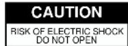

ATTENTION: RISQUE DE CHOC ELECTRIQUE NE PAS OUVRIR
CAUTION: TO REDUCE THE RISK OF ELECTRIC SHOCK,
DO NOT REMOVE COVER (OR BACK).
NO USER-SERVICEABLE PARTS INSIDE.
REFER SERVICING TO QUALIFIED SERVICE PERSONNEL.

The lightning flash with arrowhead symbol, within an equilateral triangle, is intended to alert the user to the presence of uninsulated “dangerous voltage” within the product’s enclosure that may be of sufficient magnitude to constitute a risk of electric shock to persons.

The exclamation point within an equilateral triangle is intended to alert the user to the presence of important operating and maintenance (servicing) instructions in the literature accompanying the product.
INSTRUCTIONS PERTAINING TO A RISK OF FIRE, ELECTRIC SHOCK, OR INJURY TO PERSONS.
IMPORTANT SAFETY INSTRUCTIONS SAVE THESE INSTRUCTIONS
WARNING - When using electric products, basic precautions should always be followed, including the following:
- Read these instructions.
- Keep these instructions.
- Heed all warnings.
- Follow all instructions.
- Do not use this apparatus near water.
- Clean only with a dry cloth.
- Do not block any of the ventilation openings. Install in accordance with the manufacturers instructions.
- Do not install near any heat sources such as radiators, heat registers, stoves, or other apparatus (including amplifiers) that produce heat.
-
Do not defeat the safety purpose of the polarized or grounding-type plug. A polarized plug has two blades with one wider than the other. A grounding type plug has two blades and a third grounding prong. The wide blade or the third prong are provided for your safety. When the provided plug does not fit into your outlet, consult an electrician for replacement of the obsolete outlet.
-
Protect the power cord from being walked on or pinched particularly at plugs, convenience receptacles, and the point where they exit from the apparatus.
- Only use attachments/accessories specified by the manufacturer.
- Never use with a cart, stand, tripod, bracket, or table except as specified by the manufacturer, or sold with the apparatus. When a cart is used, use caution when moving the cart/apparatus combination to avoid injury from tip-over.
- Unplug this apparatus during lightning storms or when unused for long periods of time.
- Refer all servicing to qualified service personnel. Servicing is required when the apparatus has been damaged in any way, such as power-supply cord or plug is damaged, liquid has been spilled or objects have fallen into the apparatus, the apparatus has been exposed to rain or moisture, does not operate normally, or has been dropped.

For the U.K.
WARNING: THIS APPARATUS MUST BE EARTHED
IMPORTANT: THE WIRES IN THIS MAINS LEAD ARE COLOURED IN ACCORDANCE WITH THE FOLLOWING CODE. GREEN-AND-YELLOW: EARTH, BLUE: NEUTRAL, BROWN: LIVE
As the colours of the wires in the mains lead of this apparatus may not correspond with the coloured markings identifying the terminals in your plug, proceed as follows:
The wire which is coloured GREEN-AND-YELLOW must be connected to the terminal in the plug which is marked by the letter E or by the safety earth symbol ⊕ or coloured GREEN or GREEN-AND-YELLOW.
The wire which is coloured BLUE must be connected to the terminal which is marked with the letter N or coloured BLACK. The wire which is coloured BROWN must be connected to the terminal which is marked with the letter L or coloured RED.
USING THE UNIT SAFELY
INSTRUCTIONS FOR THE PREVENTION OF FIRE, ELECTRIC SHOCK, OR INJURY TO PERSONS
About ⚠️ WARNING and ⚠️ CAUTION Notices
 | Used for instructions intended to alert the user to the risk of death or severe injury should the unit be used improperly. |
 | Used for instructions intended to alert the user to the risk of injury or material damage should the unit be used improperly.* Material damage refers to damage or other adverse effects caused with respect to the home and all its furnishings, as well to domestic animals or pets. |
About the Symbols
| The △ symbol alerts the user to important instructions or warnings. The specific meaning of the symbol is determined by the design contained within the triangle. In the case of the symbol at left, it is used for general cautions, warnings, or alerts to danger. | |
| The ⊗ symbol alerts the user to items that must never be carried out (are forbidden). The specific thing that must not be done is indicated by the design contained within the circle. In the case of the symbol at left, it means that the unit must never be disassembled. | |
| The ● symbol alerts the user to things that must be carried out. The specific thing that must be done is indicated by the design contained within the circle. In the case of the symbol at left, it means that the power-cord plug must be unplugged from the outlet. |
ALWAYS OBSERVE THE FOLLOWING
WARNING
- Before using this unit, make sure to read the instructions below, and the Owner's Manual.
- Do not open or perform any internal modifications on the unit.
- Do not attempt to repair the unit, or replace parts within it (except when this manual provides specific instructions directing you to do so). Refer all servicing to your retailer, the nearest Roland Service Center, or an authorized Roland distributor, as listed on the "Information" page.
-
Never use or store the unit in places that are:
-
Subject to temperature extremes (e.g., direct sunlight in an enclosed vehicle, near a heating duct, on top of heat-generating equipment); or are
- Damp (e.g., baths, washrooms, on wet floors); or are
- Humid; or are
- Exposed to rain; or are
- Dusty; or are
- Subject to high levels of vibration.
- Make sure you always have the unit placed so it is level and sure to remain stable. Never place it on stands that could wobble, or on inclined surfaces.
- The unit should be connected to a power supply only of the type described in the operating instructions, or as marked on the unit.


WARNING
- Do not excessively twist or bend the power cord, nor place heavy objects on it. Doing so can damage the cord, producing severed elements and short circuits. Damaged cords are fire and shock hazards!

- This unit, either alone or in combination with an amplifier and headphones or speakers, may be capable of producing sound levels that could cause permanent hearing loss. Do not operate for a long period of time at a high volume level, or at a level that is uncomfortable. If you experience any hearing loss or ringing in the ears, you should immediately stop using the unit, and consult an audiologist.

- Do not allow any objects (e.g., flammable material, coins, pins); or liquids of any kind (water, soft drinks, etc.) to penetrate the unit.

- In households with small children, an adult should provide supervision until the child is capable of following all the rules essential for the safe operation of the unit.

- Protect the unit from strong impact. (Do not drop it!)


WARNING
- Do not force the unit's power-supply cord to share an outlet with an unreasonable number of other devices. Be especially careful when using extension cords—the total power used by all devices you have connected to the extension cord's outlet must never exceed the power rating (watts/amperes) for the extension cord. Excessive loads can cause the insulation on the cord to heat up and eventually melt through.

- Before using the unit in a foreign country, consult with your retailer, the nearest Roland Service Center, or an authorized Roland distributor, as listed on the "Information" page.

Placement
- Using the unit near power amplifiers (or other equipment containing large power transformers) may induce hum. To alleviate the problem, change the orientation of this unit; or move it farther away from the source of interference.
- This device may interfere with radio and television reception. Do not use this device in the vicinity of such receivers.
- Noise may be produced if wireless communications devices, such as cell phones, are operated in the vicinity of this unit. Such noise could occur when receiving or initiating a call, or while conversing. Should you experience such problems, you should relocate such wireless devices so they are at a greater distance from this unit, or switch them off.
- Do not expose the unit to direct sunlight, place it near devices that radiate heat, leave it inside an enclosed vehicle, or otherwise subject it to temperature extremes. Also, do not allow lighting devices that normally are used while their light source is very close to the unit (such as a piano light), or powerful spotlights to shine upon the same area of the unit for extended periods of time. Excessive heat can deform or discolor the unit.
- To avoid possible breakdown, do not use the unit in a wet area, such as an area exposed to rain or other moisture.
- Do not allow rubber, vinyl, or similar materials to remain on the unit for long periods of time. Such objects can discolor or otherwise harmfully affect the finish.
- Do not put anything that contains water (e.g., flower vases) on the unit. Also, avoid the use of insecticides, perfumes, alcohol, nail polish, spray cans, etc., near the unit. Swiftly wipe away any liquid that spills on the unit using a dry, soft cloth.
- Do not paste stickers, decals, or the like to this instrument. Peeling such matter off the instrument may damage the exterior finish.
WARNING
- Do not allow objects to remain on top of the unit while it is in operation.
Additional Precautions
- Use a reasonable amount of care when using the unit's buttons, sliders, or other controls; and when using its jacks and connectors. Rough handling can lead to malfunctions.
- When connecting / disconnecting all cables, grasp the connector itself—never pull on the cable. This way you will avoid causing shorts, or damage to the cable's internal elements.
- A small amount of heat will radiate from the unit during normal operation.
- To avoid disturbing your neighbors, try to keep the unit's volume at reasonable levels. You may prefer to use headphones, so you do not need to be concerned about those around you (especially when it is late at night).
- When you need to transport the unit, package it in the box (including padding) that it came in, if possible. Otherwise, you will need to use equivalent packaging materials.
- Use a cable from Roland to make the connection. If using some other make of connection cable, please note the following precautions.
- Some connection cables contain resistors. Do not use cables that incorporate resistors for connecting to this unit. The use of such cables can cause the sound level to be extremely low, or impossible to hear. For information on cable specifications, contact the manufacturer of the cable.
- This is a heavy device. To prevent injury caused by the unit overturning or being dropped, use two or more people to carry the unit whenever possible.
WARNING
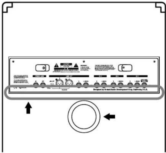
- To avoid injury, avoid placing hands at points indicated by the arrows in the following figure.
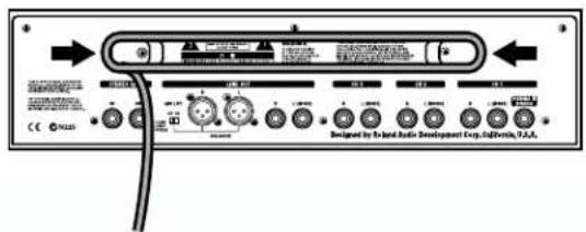
- Wrap the AC cord around the cord hook when transporting or storing the unit.
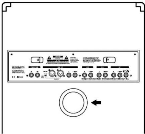
- In order to obtain optimum performance from this equipment, avoid allowing the areas indicated by the arrows in the figure below to become obstructed.
CAUTION
- The unit should be located so that its location or position does not interfere with its proper ventilation.

• Always grasp only the plug on the power-supply cord when plugging into, or unplugging from an outlet.

- Try to prevent cords and cables from becoming entangled. Also, all cords and cables should be placed so they are out of the reach of children.

- If the unit could become a hazard if it moves, all caster wheels should be removed once the unit has been placed at the place of installation, or has been loaded onto a vehicle.

- Never climb on top of, nor place heavy objects on the unit.

- Never handle the power cord or its plug with wet hands when plugging into, or unplugging from, an outlet.

- Before moving the unit, disconnect the power plug from the outlet, and pull out all cords from external devices.

- Before cleaning the unit, turn off the power and unplug the power cord from the outlet (p. 11).

- Whenever you suspect the possibility of lightning in your area, pull the plug on the power cord out of the outlet.

IMPORTANT NOTES
In addition to the items listed under "IMPORTANT SAFETY INSTRUCTIONS" and "USING THE UNIT SAFELY" on pages 2 and 5, please read and observe the following:
Power Supply
- Do not use this unit on the same power circuit with any device that will generate line noise (such as an electric motor or variable lighting system).
- Before connecting this unit to other devices, turn off the power to all units. This will help prevent malfunctions and/or damage to speakers or other devices.
Maintenance
- For everyday cleaning wipe the unit with a soft, dry cloth or one that has been slightly dampened with water. To remove stubborn dirt, use a cloth impregnated with a mild, non-abrasive detergent. Afterwards, be sure to wipe the unit thoroughly with a soft, dry cloth.
- Never use benzine, thinners, alcohol or solvents of any kind, to avoid the possibility of discoloration and/or deformation.
- For routine care of the carpeted surfaces, use a brush with stiff bristles.
Introduction
Main Features
FFP Technology
This amplifier relies on Roland's own innovative FFP technology. By digitally processing the input signal, it provides response that is geared perfectly toward amplification of the V-drums sound. At the same time, it achieves sonic pressure that surpasses the size and wattage of the cabinet.
Bi-amp System
The woofer and tweeter are each driven by a dedicated amp, so you get high-power, high-quality sound.
Dedicated input channel for V-Drums (CH1)
The amp features an input channel tailored for V-Drums sound.
V-Drums In
With this input jack, all you need is just one stereo cable to make the connection from the headphone output jack on a V-Drums sound module.
V-Drums Shape
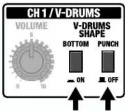
The amp features a BOTTOM switch for truly awesome bass, and a PUNCH switch for enhancing the contour of the midrange and high-end. Together, they allow you to increase the impact of the V-Drums sound.
Built-in 3-Channel Mixer Feature
Thanks to its Mixer feature, the TDA-700 makes it easy to incorporate a variety of other devices, such as percussion pads and rhythm machines, in addition to V-Drums.
And, since CH 2 and CH 3 are equipped with an OUTPUT SEL switch, which lets you select headphones, speakers, or line out as the output destination, the output for a device you've input can be changed at will.
3-Band Equalizer
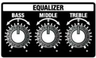
The TDA-700 is equipped with a three-band equalizer. Moreover, when combined with the Shape switch, even more tonal variations are possible.
Stereo Link
Stereo playback is made simple with a single audio cable (phone type) connection.
Channel volume can be controlled totally on the main unit.
A Cabinet Designed for Monitor Performance
The tweeter is located near the top of the cabinet, enhancing the performance of the performer's monitor speaker.
Broad Expandability
In addition to the channel inputs, the input/output connectors also include headphones output, and two types of Line Out jacks (XLR and 1/4" phone jacks), thus providing support for a wide variety of applications.

What's FFP (Feed Forward Processing) Technology?
FFP is system control technology that optimizes the performance of the amp, speakers, and cabinet characteristics according to the signals being input, based on the results of analyses of the operation and behavior of each section of existing amp systems.
Panel Descriptions
Front Panel
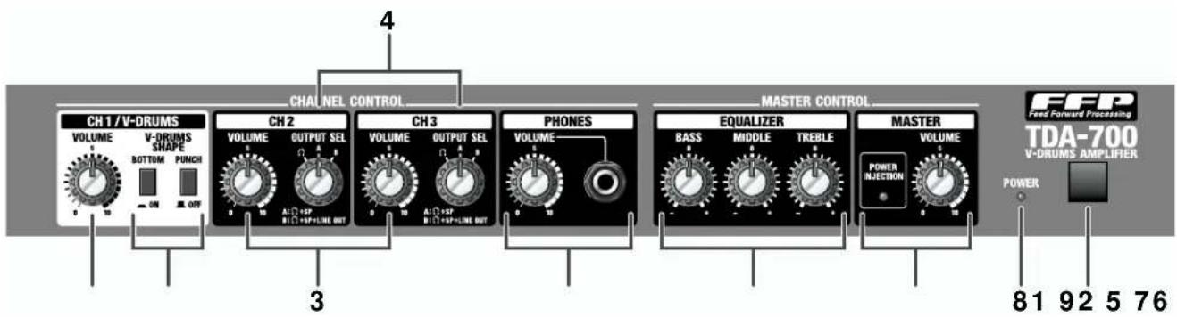
CHANNEL CONTROL ....
* When using in "Stereo Link" (p. 14) configuration, the controls explained here work only on the main unit.
- CH 1/V-DRUMS
1. VOLUME Knob
Sets the volume for CH1.
Rotating the knob clockwise increases the volume.
2. V-DRUMS SHAPE Switch
Setting this switch to ON lets you apply distinctive sound qualities to the signal input to CH 1 L, CH 1 R, or V-DRUMS IN.
BOTTOM Switch
Setting this to ON lets you boost the vividness of the low end.
PUNCH Switch
Setting this to ON lets you shape the contour of the midrange and high-end.
* This does not work on Channel 2 or 3.
- CH 2 or CH 3
3. VOLUME Knobs
Sets the volume for each channel.
Rotating a knob clockwise increases the volume.
4. OUTPUT SEL (output select) Switch
This knob allows you to select the output destination for signals input to Channel 2 and 3.
Ω: Select this position when you wish to listen to guide clicks or a drum machine (for example) through headphones, without output to the internal or any external speakers.
A: Output is through the headphones and the internal speakers. No signals are output to Line Out. This can be a handy function when you want to use the amplifier as a fold back monitor during a live performance.
This is effective in preventing the loop noise that may occur at times such as when the input (Channel 2 or 3) and Line Out on the TDA-700 are both connected to a mixer.
B: Output is through the headphones, the internal speakers, and Line Out.
5. PHONES
PHONES Jack
This is for connecting headphones.
* Before plugging in or unplugging headphones, be sure to place the PHONES VOLUME knob at 0.
* The V-DRUMS SHAPE Switch, EQUALIZER, and MASTER do not affect the headphone output.
PHONES VOLUME Knob
This knob adjusts the headphone volume.
This control does not affect LINE OUT and speaker output.
* The amplifier's speakers work even when headphones are connected.
MASTER CONTROL......
6. EQUALIZER
The TDA-700 comes with a three-band equalizer.
BASS Knob
This adjusts the tone of the bass range.
MIDDLE Knob
This adjusts the tone of the middle range.
TREBLE Knob
This adjusts the tone of the treble range.
7. MASTER
MASTER VOLUME Knob
This adjusts the total volume level of the unit's internal speaker.
* The two knobs (6) (7) in the MASTER CONTROL Section do not affect the headphone output.
POWER INJECTION Indicator
This indicator shows the power-boosting effect of FFP.
It lights green when the effect is moderate, and turns red when the effect reaches its maximum.
A red light indicates that the system is working at full power.
This indicator only applies to the speaker output.
8. POWER Switch
This switches the power on and off.
The pilot light illuminates when the power is on.
* Before turning the power on or off, be sure to put the MASTER VOLUME knob (7) at 0.
9. POWER Indicator
This indicator lights when the unit is turned on.
Rear Panel
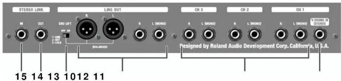
CHANNEL INPUT......
10. V-DRUMS IN Jack
This is an input that accepts a stereo signal from the V-Drums module through a single jack.
Connection is made simple using just one stereo phone cable to the module's headphone output.
11. Input Jacks
These jacks are for connecting a V-Drums sound module, backing machine, rhythm machine, etc.
If you're connecting a monaural device, connect to the L (MONO) jack of one pair.
If you're connecting a stereo device, make connections to both the L and R jacks of a pair.
LINE OUT......
12. LINE OUT Jacks
Connect a mixer or recording device to either (or both) of these pairs of outputs.
There are two types of connectors: an XLR type and an unbalanced TRS 1/4" phone jack. Use the one appropriate for the equipment you're connecting.
If you're making a mono connection, connect to the L (MONO) phone jack.
* V-DRUMS SHAPE Switch, EQUALIZER, and MASTER do not affect LINE OUT.
13. GND LIFT Switch
This selects whether the XLR-type LINE OUT jacks are grounded or not. If you encounter noise problems that are possibly caused by a ground loop, try changing the switch position to alleviate the problem.
STEREO LINK......
* For details on the Stereo Link function, refer to "Stereo Link" (p. 14).
14. STEREO LINK OUT Jack
Connect this jack to the STEREO LINK IN jack on a second TDA-700 when you wish to have true stereo output.
When a cable is connected to the STEREO LINK OUT jack, the right-channel input signals are output from the internal speakers. The left-channel input signals are output from the STEREO LINK OUT jack to the other TDA-700.
15. STEREO LINK IN Jack
Connect this jack to the STEREO LINK OUT jack on the main unit (the other TDA-700) when a true stereo output is required. Left-channel input signals are output from the internal speakers.
Connect your TDA-700
Refer to the following diagram and connect the TDA-700 to the external equipment you are using.
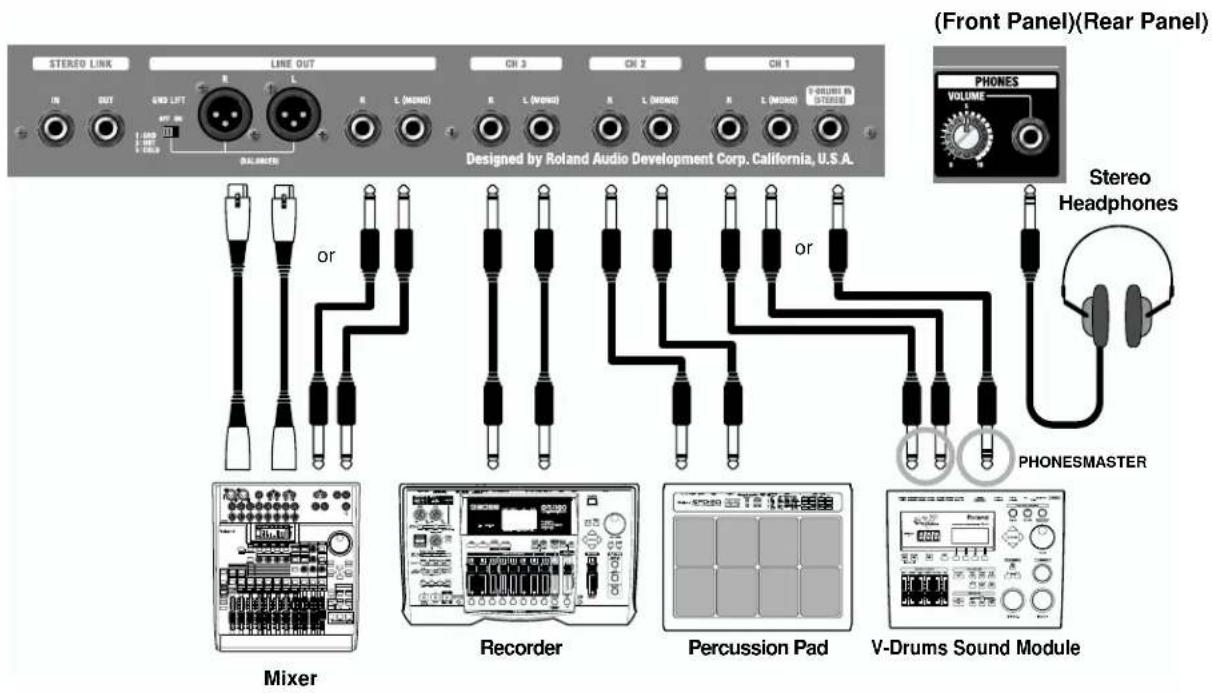
* To prevent malfunction and/or damage to speakers or other devices, always turn down the volume, and turn off the power on all devices before making any connections.
* The pin assignment for the XLR type connectors is as shown below. Before making any connections, make sure that this pin assignment is compatible with that of all your other devices.
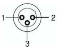
1: GND
2: HOT
3: COLD
Q: The volume level of the instrument connected to CH-1–3 is too low.
A: Could you be using a connection cable that contains a resistor?
Use a connection cable that does not contain a resistor.
Switching the power on or off
Once the connections have been completed, turn on power to your various devices in the order specified. By turning on devices in the wrong order, you risk causing malfunction and/or damage to speakers and other devices.
-
Switch on the power to the V-Drums sound module and any equipment connected to CH 1-3.
-
TDA-700
-
If a mixer is connected to the LINE OUT jack(s) on the TDA-700, turn on the mixer.
* This unit is equipped with a protection circuit. A brief interval (a few seconds) after power up is required before the unit will operate normally.
* Always make sure to have the volume level turned down before switching on/off power. Even with the volume all the way down, you may still hear some sound when the power is switched on/off, but this is normal, and does not indicate a malfunction.
Volume settings when using V-Drums sound module
For best possible sound quality, set the volume of the V-Drums sound module and TDA-700 as follows.
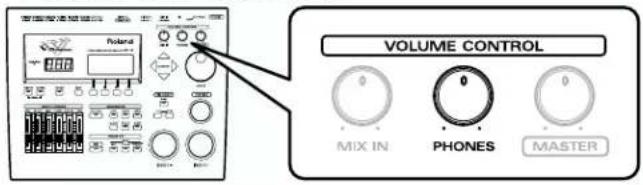
- When PHONES on the V-Drums sound generator is connected to the TDA-700's V-DRUMS IN, set the V-Drums generator's PHONES VOLUME to the center position.
• V-Drums PHONES connection
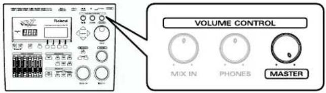
When the V-Drums sound generator's MASTER OUTPUT is connected to the TDA-700's CH 1 INPUT, set the V-Drums MASTER VOLUME to the maximum position.
• V-Drums MASTER connection
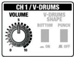
- Set the TDA-700 CH1 VOLUME to the center "5" position.
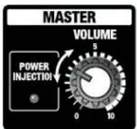
- Adjust the TDA-700's MASTER VOLUME to determine the overall volume level.
* If the POWER INJECTION indicator turns red quite often, lower MASTER VOLUME until it turns red only occasionally.
* If other sound sources are connected to CH 2, CH 3, adjust the CH2, CH3 VOLUME also.
- Adjust the tone to your liking using the V-DRUMS SHAPE Switch and the EQUALIZER.
* If you hear distortion after the adjustment, lower the CH1 VOLUME or V-Drums VOLUME until the distortion is gone.
* Above also applies to cases with other sound sources connected to CH2, CH3. In that case, lower the CH2, CH3 VOLUME or VOLUME at the sound source.
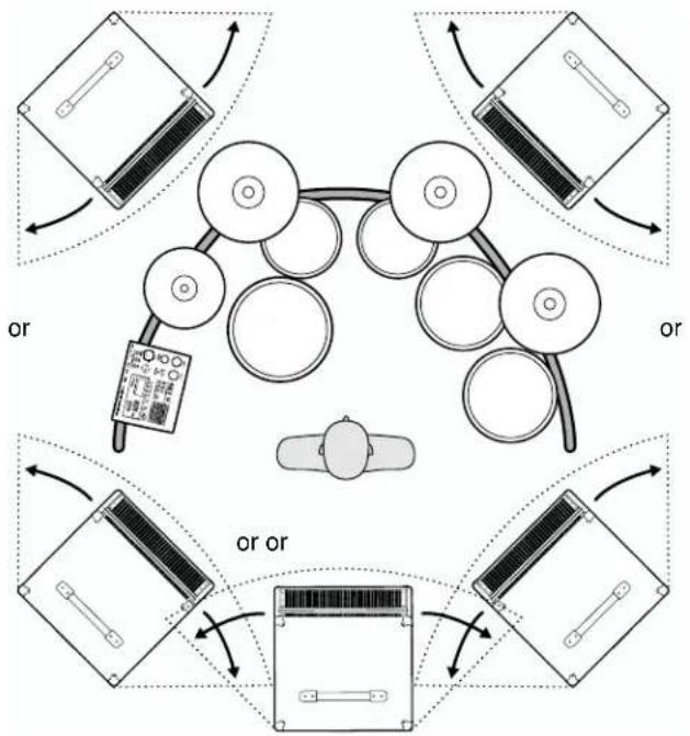
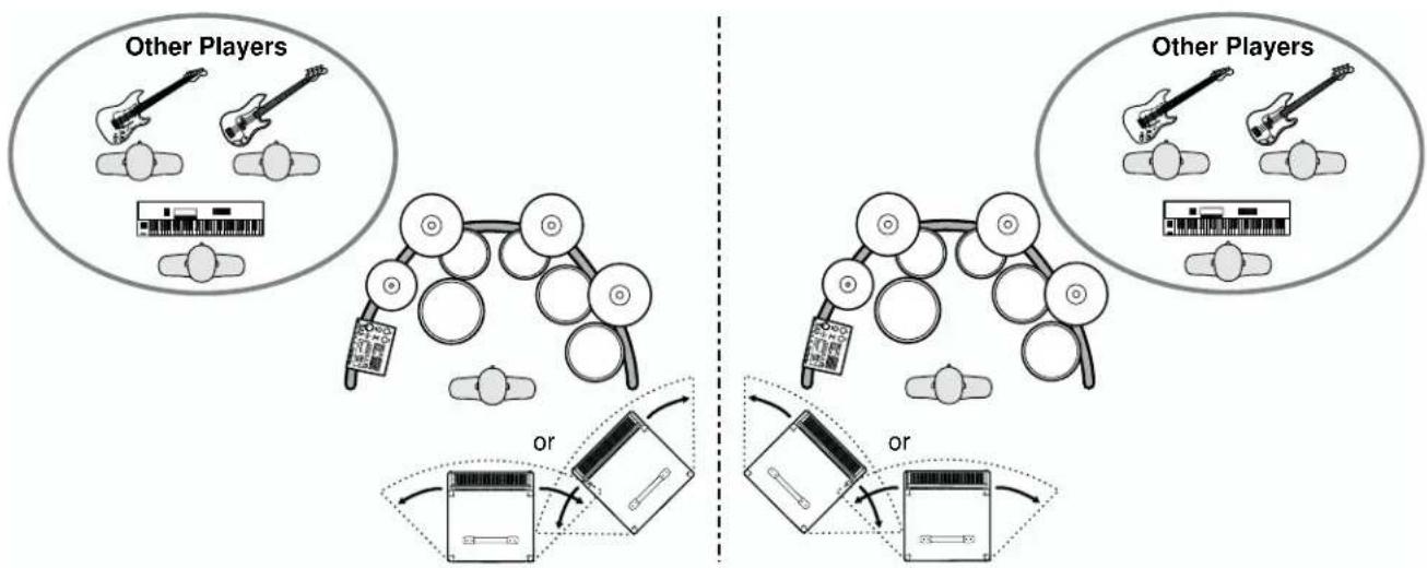
Adjust the direction of TDA-700 to suit the environment in which you are using it.
- When using TDA-700 as a personal monitor
Try several positions and angles until you find the most comfortable setup.
flowchart
graph TD
    A["Top Circular Component"] --> B["Left Circular Component"]
    B --> C["Right Circular Component"]
    C --> D["Bottom Circular Component"]
    D --> E["Left Circular Component"]
    E --> F["Right Circular Component"]
    F --> G["Bottom Circular Component"]
    G --> H["Left Circular Component"]
    H --> I["Right Circular Component"]
    I --> J["Bottom Circular Component"]
    J --> K["Left Circular Component"]
    K --> L["Right Circular Component"]
    L --> M["Bottom Circular Component"]
    M --> N["Left Circular Component"]
    N --> O["Right Circular Component"]
    O --> P["Bottom Circular Component"]
    P --> Q["Left Circular Component"]
    Q --> R["Right Circular Component"]
    R --> S["Bottom Circular Component"]
- When using TDA-700 as a monitor for the whole band
Try several positions and angles until you find a setup that is good not only for yourself, but for other players as well.
flowchart
graph TD
    A["Other Players"] --> B["Music Instrument"]
    B --> C["Play键盘"]
    C --> D["Audio System"]
    D --> E["Radio Station"]
    E --> F["Audio Device"]
    F --> G["Audio Board"]
    G --> H["Audio Assistant"]
    H --> I["Audio Record"]
    I --> J["Audio Record"]
    J --> K["Audio Record"]
    K --> L["Audio Record"]
    L --> M["Audio Record"]
    M --> N["Audio Record"]
    N --> O["Audio Record"]
    O --> P["Audio Record"]
    P --> Q["Audio Record"]
    Q --> R["Audio Record"]
    R --> S["Audio Record"]
    S --> T["Audio Record"]
    T --> U["Audio Record"]
    U --> V["Audio Record"]
    V --> W["Audio Record"]
    W --> X["Audio Record"]
    X --> Y["Audio Record"]
Stereo Link
Stereo playback is enabled simply by connecting two TDA-700 units with a single audio cable (phone type).
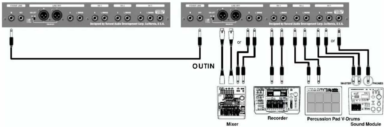
This function is called "Stereo Link." As the channel control section is designed to accept stereo signals, connection of sound sources is needed only at the main unit, thus enabling channel volumes to be centrally controlled on the main unit.
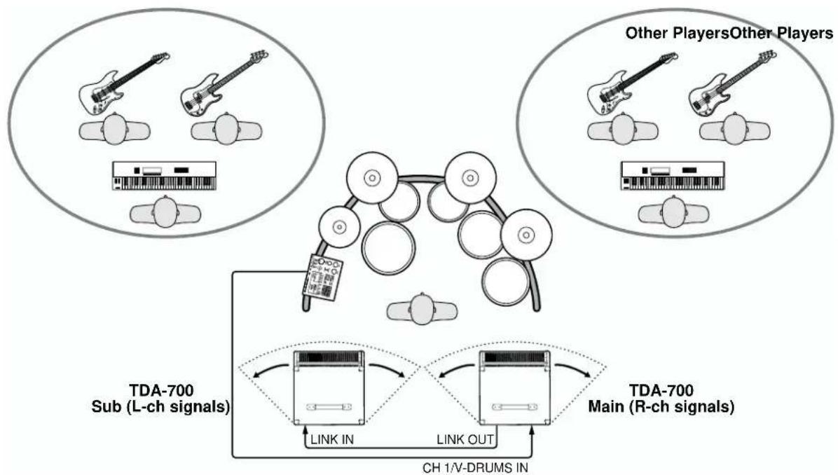
The right-channel signals are output from the speakers in the main unit, while the left-channel signals are output from the speakers in the sub unit (the other TDA-700).
Sub (L-channel signals) Main (R-channel signals)
Connections
When using a Stereo Link configuration, connect all peripheral equipment to the main unit. On the sub unit, the only functional input/output jack is STEREO LINK IN.
* Before making the connections, be sure that the volume setting of the MASTER VOLUME knob for both amplifiers is set to "0."
Switching the power on or off
Once the connections have been completed, turn on power to your various devices in the order specified. By turning on devices in the wrong order, you risk causing malfunction and/or damage to speakers and other devices.
- Turn on V-Drums sound module and other sound sources connected to CH 1–3.
- Turn on the main TDA-700 amplifier.
- Turn on the sub TDA-700 amplifier.
- Turn on the device connected to LINE OUT.
- Adjust the volume levels on all devices.
Before switching off the power, lower the volume on each of the devices in your system, then TURN OFF the devices in the reverse order of that used when switching them on.
In performance
In stereo link configuration, adjust volumes with VOLUME knobs in CH 1–CH 3 of the main unit.
* The CH 1–CH 3 VOLUME knobs of the main unit affect both the left and right units.
* CH 1–CH 3 VOLUME and V-DRUMS SHAPE are controlled on the main unit. The sub unit does not respond to these controls.
* CH 1–CH 3 VOLUME and V-DRUMS SHAPE of the sub unit are independent of the main unit.
Basically, these controls should be set to the same position. However, depending on the conditions, you may want to adjust each unit so as to better suit the situation.

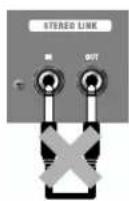
The output from STEREO LINK OUT on a device must never be input to the STEREO LINK IN on the same device. Doing so may damage the unit.
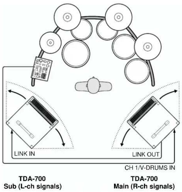
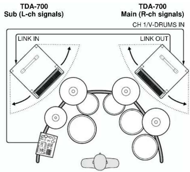
The following shows the placement of V-Drums KIT and the TDA-700 in a Stereo Link configuration.
- When using TDA-700 as a personal monitor
Place the main unit to your right. Try several positions and angles until you find the most comfortable setup.
flowchart
graph TD
    A["Sub (L-ch signals)"] --> B["Link IN"]
    C["Main (R-ch signals)"] --> D["Link OUT"]
    B --> E["Chip with 2.0x magnification"]
    D --> F["Chip with 1.5x magnification"]
    style A fill:#f9f,stroke:#333
    style C fill:#f9f,stroke:#333
    style B fill:#ccf,stroke:#333
    style D fill:#ccf,stroke:#333
    style E fill:#dfd,stroke:#333
    style F fill:#dfd,stroke:#333
flowchart
graph TD
    A["TDA-700 Sub (L-ch signals)"] --> B["LINK IN"]
    C["TDA-700 Main (R-ch signals) CH 1/V-DRUMS IN"] --> D["LINK OUT"]
    B --> E["Cell with circular elements"]
    D --> F["Cell with circular elements"]
    E --> G["Cell with circular elements"]
    F --> H["Cell with circular elements"]
    G --> I["Cell with circular elements"]
    H --> J["Cell with circular elements"]
    I --> K["Cell with circular elements"]
- When using TDA-700 as a monitor for the whole band
Place the main unit to your right. Try several positions and angles until you find a setup that is good not only for yourself, but for other players as well.
flowchart
graph TD
    A["Other Players"] --> B["TDA-700 Sub (L-ch signals)"]
    C["Other Players"] --> D["TDA-700 Main (R-ch signals)"]
    E["Other Players"] --> F["Link IN"]
    G["Other Players"] --> H["Link OUT"]
    I["Other Players"] --> J["CH 1/V-DRUMS IN"]
    K["Other Players"] --> L["Link IN"]
    M["Other Players"] --> N["Link OUT"]
    O["Other Players"] --> P["Link IN"]
    Q["Other Players"] --> R["Link OUT"]
    S["Other Players"] --> T["Link IN"]
    U["Other Players"] --> V["Link OUT"]
    W["Other Players"] --> X["Link IN"]
    Y["Other Players"] --> Z["Link OUT"]
    AA["Other Players"] --> AB["Link IN"]
    AC["Other Players"] --> AD["Link OUT"]
    AE["Other Players"] --> AF["Link IN"]
    AG["Other Players"] --> AH["Link OUT"]
    AI["Other Players"] --> AJ["Link IN"]
    AK["Other Players"] --> AL["Link OUT"]
    AM["Other Players"] --> AN["Link IN"]
    AO["Other Players"] --> AP["Link OUT"]
    AQ["Other Players"] --> AR["Link IN"]
    AS["Other Players"] --> AT["Link OUT"]
    AU["Other Players"] --> AV["Link IN"]
    AW["Other Players"] --> AX["Link OUT"]
    AY["Other Players"] --> AZ["TDA-700 Sub (L-ch signals)"]
    BA["Other Players"] --> BB["TDA-700 Main (R-ch signals)"]
Proper Use of the Casters
Attaching and Removing the Casters
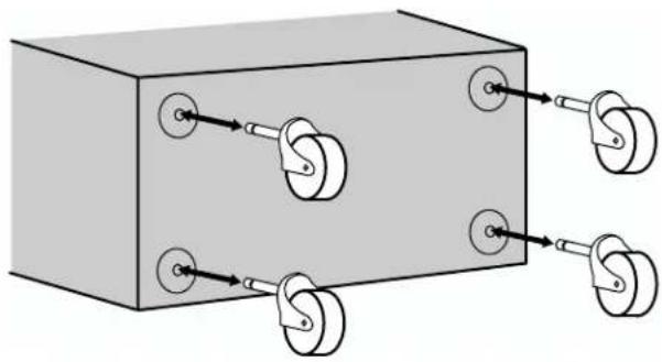
You can attach or remove the casters as shown in the following figure.

Be sure to remove all the casters when accidental movement may be dangerous, such as when setting up the TDA-700 on stage, or when transporting it in a vehicle.

This is a heavy piece of equipment. To prevent injury caused by the unit overturning or being dropped, two or more people should work together when carrying the unit.

If casters have been attached to the amp, make sure it is used only on a stable, level surface.
natural_image
Diagram of a mechanical device with pulleys and circular components, no text or symbols presentAppendices
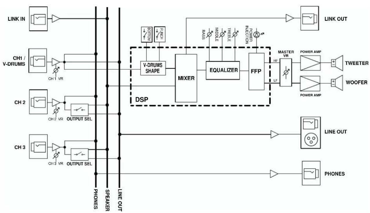
Block Diagram
flowchart
graph LR
    LINK_IN --> INV1["Switch"]
    INV1 --> INV2["Switch"]
    INV2 --> INV3["Switch"]
    INV3 --> INV4["Switch"]
    INV4 --> INV5["Switch"]
    INV5 --> INV6["Switch"]
    INV6 --> INV7["Switch"]
    INV7 --> INV8["Switch"]
    INV8 --> INV9["Switch"]
    INV9 --> INV10["Switch"]
    INV10 --> INV11["Switch"]
    INV11 --> INV12["Switch"]
    INV12 --> INV13["Switch"]
    INV13 --> INV14["Switch"]
    INV14 --> INV15["Switch"]
    INV15 --> INV16["Switch"]
    INV16 --> INV17["Switch"]
    INV17 --> INV18["Switch"]
    INV18 --> INV19["Switch"]
    INV19 --> INV20["Switch"]
    INV20 --> INV21["Switch"]
    INV21 --> INV22["Switch"]
    INV22 --> INV23["Switch"]
    INV23 --> INV24["Switch"]
    INV24 --> INV25["Switch"]
    INV25 --> INV26["Switch"]
    INV26 --> INV27["Switch"]
    INV27 --> INV28["Switch"]
    INV28 --> INV29["Switch"]
    INV29 --> INV30["Switch"]
    INV30 --> INV31["Switch"]
    INV31 --> INV32["Switch"]
    INV32 --> INV33["Switch"]
    INV33 --> INV34["Switch"]
    INV34 --> INV35["Switch"]
    INV35 --> INV36["Switch"]
    INV36 --> INV37["Switch"]
    INV37 --> INV38["Switch"]
    INV38 --> INV39["Switch"]
    INV39 --> INV40["Switch"]
    INV40 --> INV41["Switch"]
    INV41 --> INV42["Switch"]
    INV42 --> INV43["Switch"]
    INV43 --> INV44["Switch"]
    INV44 --> INV45["Switch"]
    INV45 --> INV46["Switch"]
    INV46 --> INV47["Switch"]
    INV47 --> INV48["Switch"]
    INV48 --> INV49["Switch"]
    INV49 --> INV50["Switch"]
    INV50 --> INV51["Switch"]
    INV51 --> INV52["Switch"]
    INV52 --> INV53["Switch"]
    INV53 --> INV54["Switch"]
    INV54 --> INV55["Switch"]
    INV55 --> INV56["Switch"]
    INV56 --> INV57["Switch"]
    INV57 --> INV58["Switch"]
    INV58 --> INV59["Switch"]
    INV59 --> INV60["Switch"]
    INV60 --> INV61["Switch"]
    INV61 --> INV62["Switch"]
    INV62 --> INV63["Switch"]
    INV63 --> INV64["Switch"]
    INV64 --> INV65["Switch"]
    INV65 --> INV66["Switch"]
    INV66 --> INV67["Switch"]
    INV67 --> INV68["Switch"]
    INV68 --> INV69["Switch"]
    INV69 --> INV70["Switch"]
    INV70 --> INV71["Switch"]
    INV71 --> INV72["Switch"]
    INV72 --> INV73["Switch"]
    INV73 --> INV74["Switch"]
    INV74 --> INV75["Switch"]
    INV75 --> INV76["Switch"]
    INV76 --> INV77["Switch"]
    INV77 --> INV78["Switch"]
    INV78 --> INV79["Switch"]
    INV79 --> INV80["Switch"]
    INV80 --> INV81["Switch"]
    INV81 --> INV82["Switch"]
    INV82 --> INV83["Switch"]
    INV83 --> INV84["Switch"]
    INV84 --> INV85["Switch"]
    INV85 --> INV86["Switch"]
    INV86 --> INV87["Switch"]
    INV87 --> INV88["Switch"]
    INV88 --> INV89["Switch"]
    INV89 --> INV90["Switch"]
    INV90 --> INV91["Switch"]
    INV91 --> INV92["Switch"]
    INV92 --> INV93["Switch"]
    INV93 --> INV94["Switch"]
    INV94 --> INV95["Switch"]
    INV95 --> INV96["Switch"]
    INV96 --> INV97["Switch"]
    INV97 --> INV98["Switch"]
    INV98 --> INV99["Switch"]
Specifications
Rated Power Output
300 W (LF 240 W + HF 60 W)
Nominal Input Level (1 kHz)
CHANNEL INPUT (CH1–CH3): -20 dBu
STEREO LINK INPUT: +4 dBu
Nominal Output Level (1 kHz)
LINE OUT: +4 dBu (XLR type, Phone type)
STEREO LINK OUTPUT: +4 dBu
* 0 dBu = 0.775 Vrms
Speakers
38 cm (15 inches) x1
Horn Tweeter x 1
Controls
CHANNEL CONTROL
CH1
VOLUME Knob
V-DRUMS SHAPE BOTTOM Switch
V-DRUMS SHAPE PUNCH Switch
CH2
VOLUME Knob
OUTPUT SELECT Knob
CH3
VOLUME Knob
OUTPUT SELECT Knob
PHONES
VOLUME Knob
MASTER CONTROL
EQUALIZER
BASS Knob
MIDDLE Knob
TREBLE Knob
MASTER VOLUME Knob
POWER Switch
GND LIFT Switch
Indicators
POWER INJECTION (2 colors)
POWER
Connectors
V-DRUMS IN Jack (Stereo 1/4" phone type)
CH1-CH3 INPUT L Jacks (1/4" phone type)
CH1-CH3 INPUT R Jacks (1/4" phone type)
LINE OUT L Jacks (XLR type, 1/4" phone type)
LINE OUT R Jacks (XLR type, 1/4" phone type)
STEREO LINK IN Jack (1/4" phone type)
STEREO LINK OUT Jack (1/4" phone type)
PHONES Jack (stereo 1/4" phone type)
Power Supply
AC 117, 230, 240 V
Power Consumption
260 W
Dimensions
* In the interest of product improvement, the specifications and/or appearance of this unit are subject to change without prior notice.
CE
For EU Countries
This product complies with the requirements of European Directives EMC 89/336/EEC and LVD 73/23/EEC.
-For the USA
FEDERAL COMMUNICATIONS COMMISSION RADIO FREQUENCY INTERFERENCE STATEMENT
This equipment has been tested and found to comply with the limits for a Class B digital device, pursuant to Part 15 of the FCC Rules. These limits are designed to provide reasonable protection against harmful interference in a residential installation. This equipment generates, uses, and can radiate radio frequency energy and, if not installed and used in accordance with the instructions, may cause harmful interference to radio communications. However, there is no guarantee that interference will not occur in a particular installation. If this equipment does cause harmful interference to radio or television reception, which can be determined by turning the equipment off and on, the user is encouraged to try to correct the interference by one or more of the following measures:
– Reorient or relocate the receiving antenna.
– Increase the separation between the equipment and receiver.
- Connect the equipment into an outlet on a circuit different from that to which the receiver is connected.
- Consult the dealer or an experienced radio/TV technician for help.
This device complies with Part 15 of the FCC Rules. Operation is subject to the following two conditions:
(1) This device may not cause harmful interference, and
(2) This device must accept any interference received, including interference that may cause undesired operation.
Unauthorized changes or modification to this system can void the users authority to operate this equipment.
This equipment requires shielded interface cables in order to meet FCC class B Limit.
For Canada
NOTICE
This Class B digital apparatus meets all requirements of the Canadian Interference-Causing Equipment Regulations.
AVIS


- Contents
- IMPORTANT SAFETY INSTRUCTIONS SAVE THESE INSTRUCTIONS
- USING THE UNIT SAFELY
- INSTRUCTIONS FOR THE PREVENTION OF FIRE, ELECTRIC SHOCK, OR INJURY TO PERSONS
- ALWAYS OBSERVE THE FOLLOWING
- WARNING
- Placement
- Additional Precautions
- CAUTION
- IMPORTANT NOTES
- Power Supply
- Maintenance
- Introduction
- Main Features
- FFP Technology
- Bi-amp System
- Dedicated input channel for V-Drums (CH1)
- V-Drums In
- V-Drums Shape
- Built-in 3-Channel Mixer Feature
- 3-Band Equalizer
- Stereo Link
- A Cabinet Designed for Monitor Performance
- Broad Expandability
- What's FFP (Feed Forward Processing) Technology?
- Panel Descriptions
- Front Panel
- CHANNEL CONTROL ....
- - CH 1/V-DRUMS
- VOLUME Knob
- V-DRUMS SHAPE Switch
- BOTTOM Switch
- PUNCH Switch
- - CH 2 or CH 3
- VOLUME Knobs
- OUTPUT SEL (output select) Switch
- PHONES
- PHONES Jack
- PHONES VOLUME Knob
- MASTER CONTROL......
- EQUALIZER
- BASS Knob
- MIDDLE Knob
- TREBLE Knob
- MASTER
- MASTER VOLUME Knob
- POWER INJECTION Indicator
- POWER Switch
- POWER Indicator
- Rear Panel
- CHANNEL INPUT......
- V-DRUMS IN Jack
- Input Jacks
- LINE OUT......
- LINE OUT Jacks
- GND LIFT Switch
- STEREO LINK......
- STEREO LINK OUT Jack
- STEREO LINK IN Jack
- Connect your TDA-700
- Switching the power on or off
- Volume settings when using V-Drums sound module
- - When using TDA-700 as a personal monitor
- - When using TDA-700 as a monitor for the whole band
- Connections
- In performance
- Proper Use of the Casters
- Attaching and Removing the Casters
- Appendices
- Specifications
- Rated Power Output
- Nominal Input Level (1 kHz)
- Nominal Output Level (1 kHz)
- Speakers
- Controls
- MASTER CONTROL
- Indicators
- Connectors
- Power Consumption
- Dimensions
- CE
- FEDERAL COMMUNICATIONS COMMISSION RADIO FREQUENCY INTERFERENCE STATEMENT
- NOTICE
- AVIS
Brand : ROLAND
Model : TDA-700
Category : Drum machine