
VE-RMK1U - Uncategorized ATEN - Free user manual and instructions
Find the device manual for free VE-RMK1U ATEN in PDF.


User questions about VE-RMK1U ATEN
0 question about this device. Answer the ones you know or ask your own.
Ask a new question about this device
Download the instructions for your Uncategorized in PDF format for free! Find your manual VE-RMK1U - ATEN and take your electronic device back in hand. On this page are published all the documents necessary for the use of your device. VE-RMK1U by ATEN.
USER MANUAL VE-RMK1U ATEN
Be sure to register your product at our online support center:
International http://eservice.aten.com
Telephone Support
For telephone support, call this number:
| International 886-2-8692-6959 |
| China 86-400-810-0-810 |
| Japan 81-3-5615-5811 |
| Korea 82-2-467-6789 |
| North America 1-888-999-ATEN ext 4988 |
| 1-949-428-1111 |
User Notice
All information, documentation, and specifications contained in this manual are subject to change without prior notification by the manufacturer. The manufacturer makes no representations or warranties, either expressed or implied, with respect to the contents hereof and specifically disclaims any warranties as to merchantability or fitness for any particular purpose. Any of the manufacturer's software described in this manual is sold or licensed as is. Should the programs prove defective following their purchase, the buyer (and not the manufacturer, its distributor, or its dealer), assumes the entire cost of all necessary servicing, repair and any incidental or consequential damages resulting from any defect in the software.
The manufacturer of this system is not responsible for any radio and/or TV interference caused by unauthorized modifications to this device. It is the responsibility of the user to correct such interference.
The manufacturer is not responsible for any damage incurred in the operation of this system if the correct operational voltage setting was not selected prior to operation.
PLEASE VERIFY THAT THE VOLTAGE SETTING IS CORRECT BEFORE USE.
© Copyright 2021 ATEN® International Co., Ltd.
Released: 2021-01-27
ATEN and the ATEN logo are registered trademarks of ATEN International Co., Ltd. All rights reserved. All other brand names and trademarks are the registered property of their respective owners.
Package Contents
◆ 1 VE-RMK1U Frame
◆ 4 1U Mounting Plates
◆ 5 Plastic Captive Screws
◆ 6 Hexagon Head Screws
◆ 12 Countersunk Head Screws
Note:
- Check to make sure that all the package contents are present and that nothing is damaged in shipping. If you encounter any problems, contact your local sales representative for more information.
- Read this manual thoroughly and follow the installation and operation procedures carefully to prevent any damage to the unit or any connected devices.
- ATEN regularly updates its product documentation for new features and fixes. For an up-to-date VE-RMK1U documentation, visit http://www.aten.com/global/en/
Product Information
For information about all ATEN products and how they can help you connect without limits, visit ATEN on the Web or contact an ATEN Authorized Reseller. Visit ATEN on the Web for a list of locations and telephone numbers:
| International http://www.aten.com |
| North America http://www.aten-usa.com |
Contents
User Information .... ii
Package Contents ....iii
Product Information....iii
Contents iv
Installation 1
Technical Support 12
Limited Warranty 13
- Different ATEN devices use different sets of screw holes on the mounting plate to install. Use the table below to find out:
◆ Whether if your ATEN device is built-in with rack ears
◆ The alignment line that your ATEN device uses
| Models Mounting Plate | ||||
| Category | Not Equipped with Rack Ears | Equipped with Rack Ears | Alignment Line | Max. No. of Units |
| CE CE100 - | Line A | 4 units | ||
| VE VE560, | VE600A, VE602, VE800A, VE803, VE810 | VE601, VE801, VE811, VE901 | ||
| VE VE150A, | VE170, VE172R, VB802 | - Line B | 3 units | |
| CE CE250A, | CE611, CE700A | - | Line C | |
| CS CS72D, | CS72E - | |||
| KE KE6900ST - | ||||
| VE VE812, | VE814, VE882, VE892 | VE1812, VE2812T, VE2812R, VE2812AT, VE802, VE814A, VE8900, VE8950 | ||
| VS VS182A, | VS182B, VS192, VS194 | - | ||
| UC UC2322, | UC2324, UC4852, UC4854 | - | ||
| CE CE350, | CE370, CE600, CE602, CE604, CE610A, CE620, CE624, CE750, CE750A, CE770, CE800B, CE820, CE920, CE924 | - | Line C 2 units | |
| KA KA8270, | KA8280, KA8278, KA8288 | |||
| CN CN8000, | CN8000A - | |||
| CS CS724KM, | CS74D, CS74E | - | ||
| KE KE8900S, | KE9900ST - | |||
| VC VC880, | VC486 - | |||
| VE VE300, | VE500, VE813A, VE66DTH | VE816R, VE883, VE3912T, VE8952 | ||
| VS VS184B, | VS481A, VS481B, VS481C | - | ||
-
To install a device that is equipped with rack ears, go to the next step. To install a device that is not equipped with rack ears, go to step 4 (page 6).
-
Follow the steps below to rack mount a device that has rack ears.
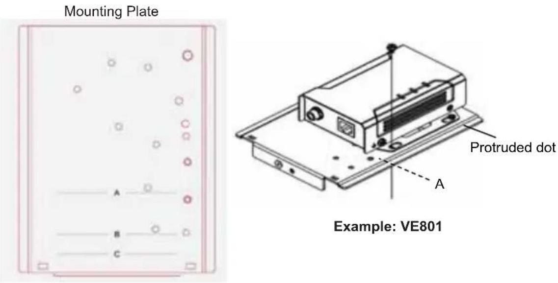
a) Align the device to its alignment line in as illustrated, and latch one of the rack ears onto the protruded dot on the mounting plate.
text_image
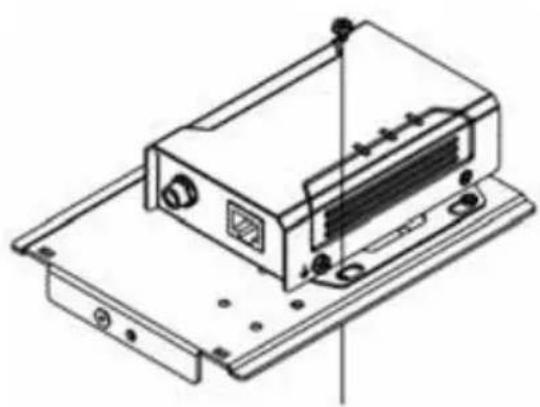
Mounting Plate A B C Protruded dot A Example: VE801b) Secure the device to the mounting plate using the supplied hexagon head screw.
natural_image
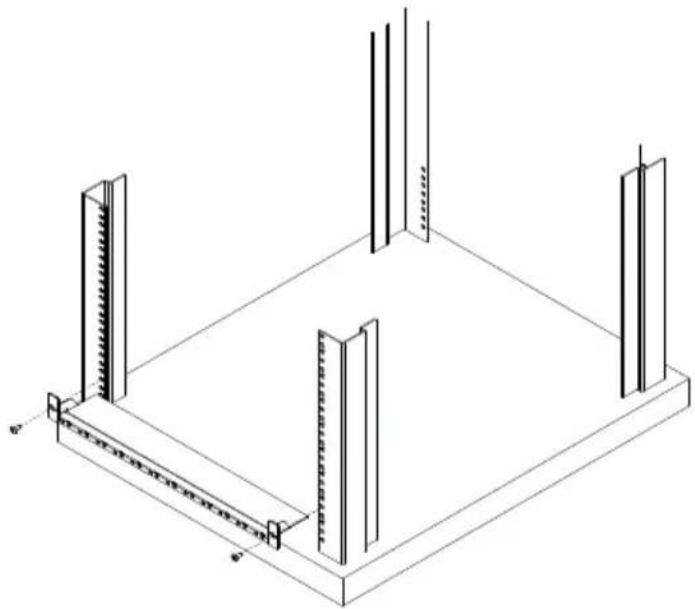
Technical line drawing of an electronic device with ports and mounting base (no text or symbols)c) Position the VE-RMK1U frame on the front of your rack, align the holes in the frame with the holes in the rack, and then secure the frame to the rack with self-prepared screws.
natural_image
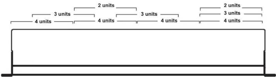
Isometric line drawing of a structural frame with vertical supports and a central horizontal beam (no text or symbols)d) Align your device and mounting plate assembly to one of the slots on the VE-RMK1U Frame.
text_image
4 units 3 units 2 units 4 units 3 units 4 units 2 units 3 units 4 unitsVE-RMK1U Frame
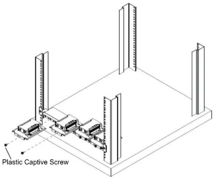
e) Secure the mounting plate to the frame with a plastic captive screw provided in the package.
text_image
Plastic Captive ScrewNote:
- The maximum number of units that a VE-RMK1U Frame supports may vary across models. Refer to the table in step 1 for details.
-
If you have any VE8900/8950 devices installed on the mounting plate, make sure to leave at least 2 mm of space above the devices to avoid scratching the buttons on the top panel, or leave 1U of space if you wish to access these buttons.
-
Follow the steps below to rack mount a device that does not have rack ears.
Example 1: For devices that align to line A or B
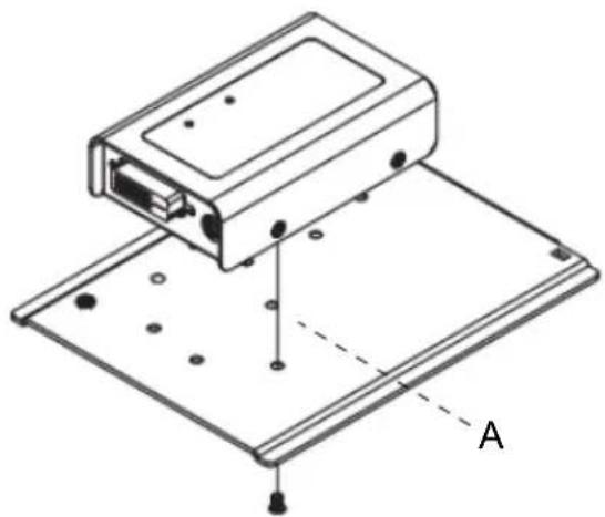
a) Align the device to line A or B in the illustrated orientation.
natural_image
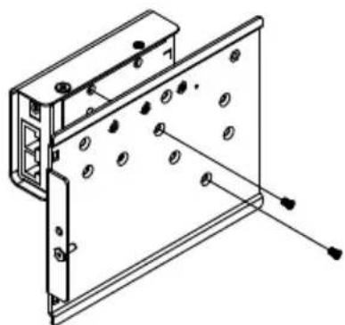
Technical line drawing of an electronic device with mounting base and labeled point A (no text or symbols beyond label)b) Secure the device to the mounting plate from the backside using the supplied countersunk head screws.
natural_image
Technical line drawing of a mechanical assembly with mounting holes and a bracket (no text or symbols)Example: VE800A
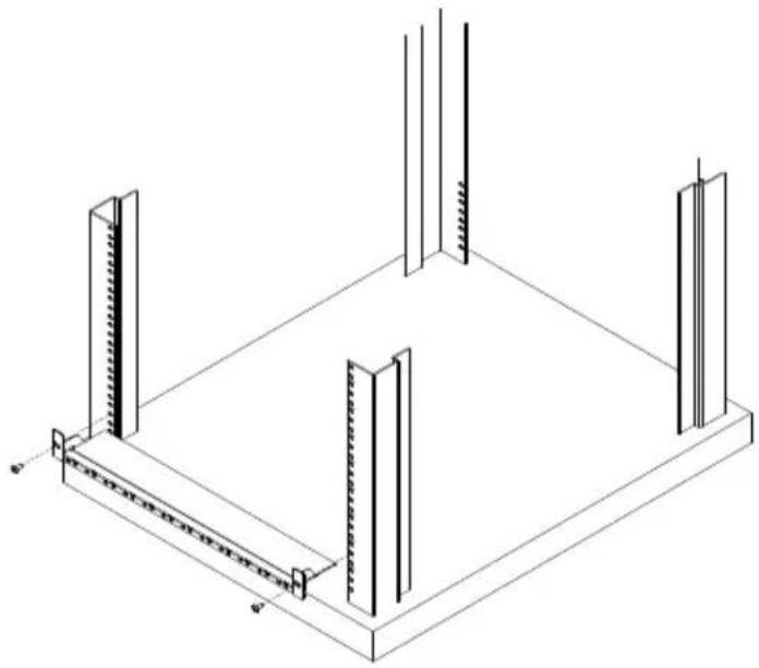
c) Position the VE-RMK1U frame on the front of your rack, align the holes in the frame with the holes in the rack, and then secure the frame to the rack with self-prepared screws.
natural_image
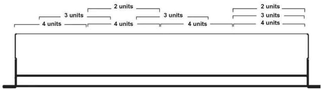
Isometric line drawing of a structural frame with vertical supports and a central horizontal beam (no text or symbols)d) Align your device and mounting plate assembly to one of the slots on the VE-RMK1U Frame.
text_image
4 units 3 units 2 units 3 units 4 units 2 units 3 units 4 unitsVE-RMK1U Frame
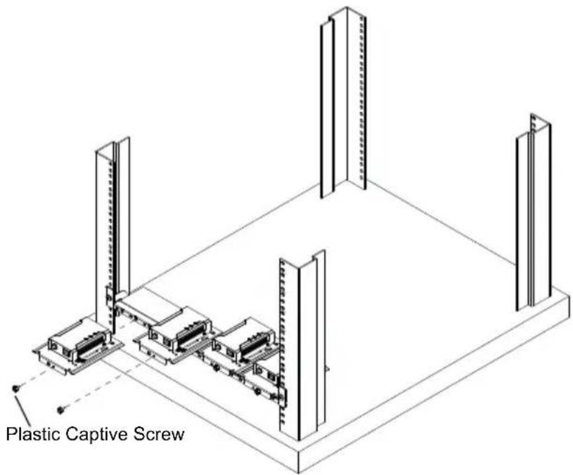
e) Secure the mounting plate to the frame with a plastic captive screw provided in the package.
For a device that aligns to line A, you can install up to 4 units:
text_image
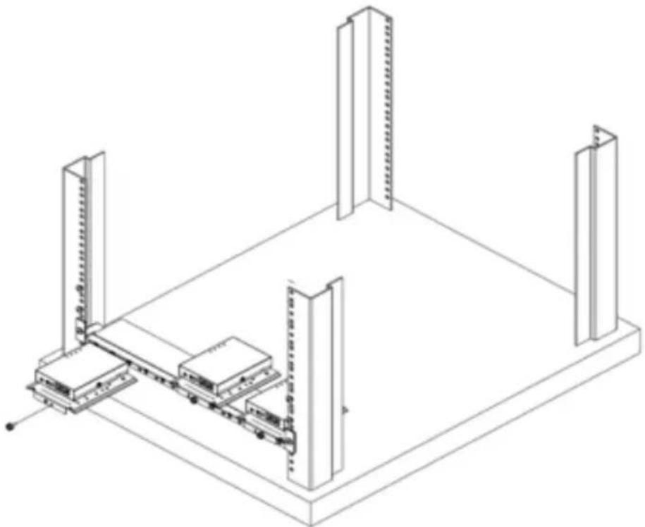
Plastic Captive ScrewFor a device that aligns to line B, you can install up to 3 units:
natural_image
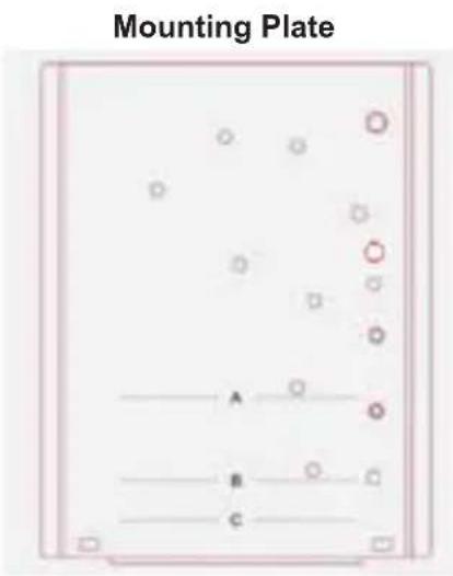
Isometric line drawing of a mechanical assembly with vertical supports and a central cart (no text or symbols)Example 2: A device that uses line C
a) Align the device to its alignment line in the illustrated orientation.
text_image
Mounting Plate A B C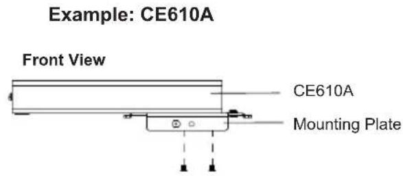
text_image
Example: CE610A Front View CE610A Mounting Plate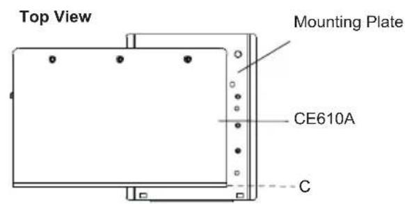
text_image
Top View Mounting Plate CE610A Cb) Secure the device to the mounting plate from the backside using the supplied countersunk head screws.
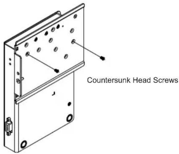
text_image
Countersunk Head Screwsc) Position the VE-RMK1U frame on the front of your rack, align the holes in the frame with the holes in the rack, and then secure the frame to the rack with self-prepared screws.
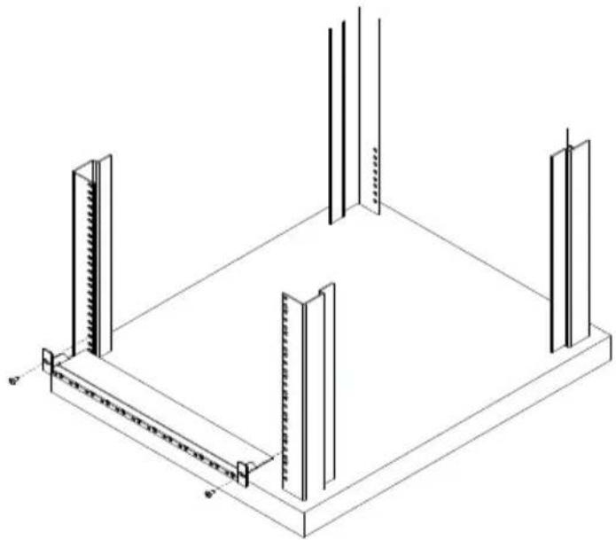
natural_image
Isometric line drawing of a structural frame with vertical supports and a central horizontal beam (no text or symbols)d) Align your device and mounting plate assembly to one of the slots on the VE-RMK1U Frame.
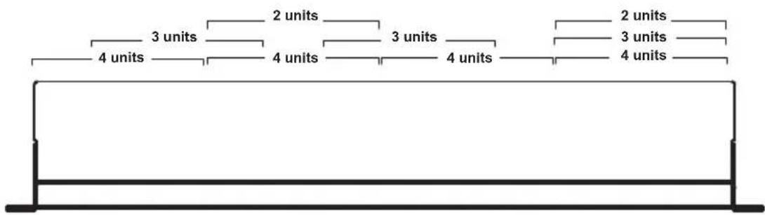
text_image
4 units 3 units 2 units 4 units 3 units 4 units 2 units 3 units 4 unitsVE-RMK1U Frame
e) Secure the mounting plate to the frame with a plastic captive screw provided in the package.
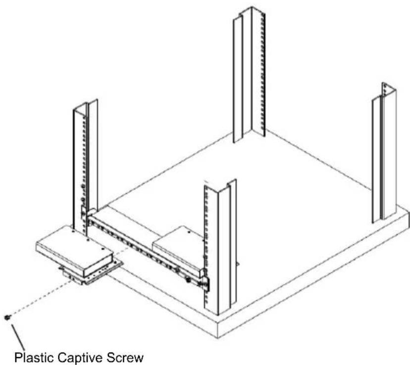
text_image
Plastic Captive ScrewNote: The maximum number of units that a VE-RMK1U Frame supports may vary across models. Refer to the table in step 1 for details.
Technical Support
International
- For online technical support – including troubleshooting, documentation, and software updates: http://support.aten.com
- For telephone support, call this number:
| International 886-2 | 8692-6959 |
| China 86-400-810-0 | 810 |
| Japan 81-3-5615-5811 | |
| Korea 82-2-467-6789 | |
| North America 1-888 | 8-999-ATEN ext 4988 |
| 1-949-428-1111 | |
North America
| Email Support support@aten-usa.com | ||
| Online Technical Support | Troubleshooting Documentation Software Updates | http://www.aten-usa.com/support |
| Telephone Support 1-888-999-ATEN ext 4988 | ||
When you contact us, please have the following information ready beforehand:
Product model number, serial number, and date of purchase
- Your computer configuration, including operating system, revision level, expansion cards, and software
◆ Any error messages displayed at the time the error occurred
◆ The sequence of operations that led up to the error
◆ Any other information you feel may be of help
Limited Warranty
ATEN warrants its hardware in the country of purchase against flaws in materials and workmanship for a Warranty Period of two [2] years (warranty period may vary in certain regions/countries) commencing on the date of original purchase. This warranty period includes the LCD panel of ATEN LCD KVM switches. Select products are warranted for an additional year (see A+ Warranty for further details). Cables and accessories are not covered by the Standard Warranty.
What is covered by the Limited Hardware Warranty
ATEN will provide a repair service, without charge, during the Warranty Period. If a product is detective, ATEN will, at its discretion, have the option to (1) repair said product with new or repaired components, or (2) replace the entire product with an identical product or with a similar product which fulfills the same function as the defective product. Replaced products assume the warranty of the original product for the remaining period or a period of 90 days, whichever is longer. When the products or components are replaced, the replacing articles shall become customer property and the replaced articles shall become the property of ATEN.
To learn more about our warranty policies, please visit our website: http://www.aten.com/global/en/legal/policies/warranty-policy/