
VE8900R - AV Extender ATEN - Free user manual and instructions
Find the device manual for free VE8900R ATEN in PDF.


| Product Type | 4K HDMI Over IP Extender |
| Model | VE8900R |
| Brand | ATEN |
| Video Resolution | Up to 4K@60Hz (3840x2160) |
| HDMI Compliance | HDMI 2.0, HDCP 2.2 |
| Audio Support | PCM, Dolby Digital, DTS, 7.1ch |
| Transmission Distance | Up to 100m via single Cat6 cable |
| Power Supply | PoE (Power over Ethernet) or DC 5V/2A |
| Dimensions (W x D x H) | 200 x 150 x 30 mm |
| Weight | 0.5 kg |
| Operating Temperature | 0°C to 50°C |
| Storage Temperature | -20°C to 60°C |
| Humidity | 0-80% RH, non-condensing |
| Chassis Material | Metal |
| LED Indicators | Power, Link, Status |
| Connectors | 1x HDMI input, 1x HDMI output, 1x RJ-45 (PoE), 1x DC jack |
| IR Extension | Built-in IR pass-through |
| RS-232 Support | Yes, for serial control |
| Maintenance | Clean with soft dry cloth; avoid liquids |
| Safety | Use included power adapter only; do not expose to moisture |
| Spare Parts | HDMI cables, power adapter, mounting brackets (sold separately) |
| Repairability | No user-serviceable parts; contact ATEN support |
| General Information | Supports HDR10, Dolby Vision; plug-and-play installation |
Frequently Asked Questions - VE8900R ATEN
User questions about VE8900R ATEN
0 question about this device. Answer the ones you know or ask your own.
Ask a new question about this device
Download the instructions for your AV Extender in PDF format for free! Find your manual VE8900R - ATEN and take your electronic device back in hand. On this page are published all the documents necessary for the use of your device. VE8900R by ATEN.
USER MANUAL VE8900R ATEN
EMC Information
FEDERAL COMMUNICATIONS COMMISSION INTERFERENCE STATEMENT: This equipment has been tested and found to comply with the limits for a Class A digital device, pursuant to Part 15 of the FCC Rules. These limits are designed to provide reasonable protection against harmful interference when the equipment is operated in a commercial environment. This equipment generates, uses, and can radiate radio frequency energy and, if not installed and used in accordance with the instruction manual, may cause harmful interference to radio communications. Operation of this equipment in a residential area is likely to cause harmful interference in which case the user will be required to correct the interference at his own expense.
FCC Caution: Any changes or modifications not expressly approved by the party responsible for compliance could void the user's authority to operate this equipment.
Warning: Operation of this equipment in a residential environment could cause radio interference.
Suggestion: Shielded twisted pair (STP) cables must be used with the unit to ensure compliance with FCC & CE standards.
This device complies with Part 15 of the FCC Rules. Operation is subject to the following two conditions: (1) this device may not cause harmful interference, and (2) this device must accept any interference received, including interference that may cause undesired operation.
RoHS
This product is RoHS compliant.

About This Manual
This User Manual is provided to help you get the most from your VE8900 / VE8950 device and the ATEN VE Manager. It covers all aspects of installation, configuration, and operation. An overview of the information found in the manual is provided below.
Chapter 1, Introduction and Getting Started, introduces you to the features and purposes of VE8900 / VE8950 HDMI over IP Video Extenders.
Chapter 2, Hardware Setup, introduces you to panel components and provides step-by-step instructions for installing and setting up your VE8900 / VE8950 hardware.
Chapter 3, Panel Operation, provides LED indicator information and functions of the panel pushbuttons.
Chapter 4, Management, provides an overview of the VE Manager's main screen and step-by-step instructions of creating and editing display layouts.
Chapter 5, System Settings, provides information on the general settings, and how to back up, restore, and upgrade the VE8900 / VE8950 system firmware.
Chapter 6, CLI Commands, provides information on required configurations for establishing sessions via telnet, TCP, or RS-232 serial signals, and list of supported CLI commands.
Chapter 7, Mobile Control App, provides information on installing, configuring, and using the application.
Appendix, provides product safety instructions, technical support details, and product specifications.
Conventions
This manual uses the following conventions:
Monospaced Indicates text that you should key in.
[] Indicates keys you should press. For example, [Enter] means to press the Enter key. If keys need to be chorded, they appear together in the same bracket with a plus sign between them: [Ctrl+Alt].
- Numbered lists represent procedures with sequential steps.
◆ Bullet lists provide information, but do not involve sequential steps.
→ Indicates selecting the option (on a menu or dialog box, for example), that comes next. For example, Start → Run means to open the Start menu, and then select Run.

Indicates critical information.
Product Information
For information about all ATEN products and how they can help you connect without limits, visit ATEN on the Web or contact an ATEN Authorized Reseller. Visit ATEN on the Web for a list of locations and telephone numbers:
| International http://www.aten.com |
| North America http://www.aten-usa.com |
User Information
Online Registration
Be sure to register your product at our online support center:
International http://eservice.aten.com
Telephone Support
For telephone support, call this number:
| International 886-2-86 | 92-6959 |
| China 86-400-810-0-8 | 10 |
| Japan 81-3-5615-5811 | |
| Korea 82-2-467-6789 | |
| North America 1-888- | 999-ATEN ext 4988 |
| 1-949-428-1111 |
User Notice
All information, documentation, and specifications contained in this manual are subject to change without prior notification by the manufacturer. The manufacturer makes no representations or warranties, either expressed or implied, with respect to the contents hereof and specifically disclaims any warranties as to merchantability or fitness for any particular purpose. Any of the manufacturer's software described in this manual is sold or licensed as is. Should the programs prove defective following their purchase, the buyer (and not the manufacturer, its distributor, or its dealer), assumes the entire cost of all necessary servicing, repair and any incidental or consequential damages resulting from any defect in the software.
The manufacturer of this system is not responsible for any radio and/or TV interference caused by unauthorized modifications to this device. It is the responsibility of the user to correct such interference.
The manufacturer is not responsible for any damage incurred in the operation of this system if the correct operational voltage setting was not selected prior to operation. PLEASE VERIFY THAT THE VOLTAGE SETTING IS CORRECT BEFORE USE.
Package Contents
Check to make sure that all of the components are present and in good order. If anything is missing or was damaged in shipping, contact your dealer.
VE8900T
1 VE8900 HDMI over IP Transmitter
1 RS-232 Terminal Block
1 5V Power Adapter
1 User Instructions
VE8900R
1 VE8900 HDMI over IP Receiver
1 RS-232 Terminal Block
1 5V Power Adapter
1 User Instructions
VE8950T
1 VE8950 4K HDMI over IP Transmitter
1 RS-232 Terminal Block
1 5V Power Adapter
1 User Instructions
VE8950R
1 VE8950 4K HDMI over IP Receiver
1 RS-232 Terminal Block
1 5V Power Adapter
1 User Instructions
Read this manual thoroughly and follow the installation and operation procedures carefully to prevent any damage to the device or to any other connected devices.
Note: The VE8900 / VE8950 product firmware may have been updated with new features after the release of this manual. For an up-to-date VE8900 / VE8950 user manual, visit http://www.aten.com/global/en/
Contents
EMC Information....ii
About This Manual ....iii
Conventions....iv
Product Information ....iv
User Information v
Package Contents ......vi
Contents ......viii
1. Introduction and Getting Started
Overview....1
Features and Benefits....2
Getting Started Tasks....6
2. Hardware Setup
Components 7
VE8900T / VE8950T Rear View 8
VE8900R / VE8950R Front View 8
Mounting the VE8900 / VE8950 Device 10
Wall Mount 10
Rack Mount....10
Connecting VE8900 / VE8950 11
3. Panel Operation
Overview....15
Status LEDs 15
Panel Controls 16
Assigning Sources Using the Device Panel 18
4. Management
Overview....19
Looking Up the Login IP Address....20
Find My VE Extension 21
Start VE Manager using Find My VE Extension 23
Logging In and Configuring VE Manager 25
The Main Screen 28
Apply / Auto Apply. 29
Assigning Sources Using VE Manager 30
Configuring and Setting Up a Video Wall 33
Creating a Video Wall Layout 34
Editing a Video Wall Layout 36
Editing a Preview 37
Profile 38
Creating a Profile. 38
Edit, Delete and Disconnect Profile. 40
Edit. 40
Delete 41
Disconnect....41
Select / Apply Profile 42
Setup Profile Schedules 43
Managing VE8900 / VE8950 Devices 46
Checking VE8900 / VE8950 Statuses. 46
5. System Settings
Overview 47
General Settings....47
Transmitter Settings 49
Receiver Settings 51
Batch Configuration 53
Maintenance 55
Upgrading VE8900 / VE8950 Device Firmware 55
Synchronizing All Devices .....56
Backing Up VE8900 / VE8950 Device Settings .....56
Restoring VE8900 / VE8950 Device Settings 57
Account Settings 58
6. CLI Commands
Overview 59
Before You Start 59
Executing Commands 60
Commands 62
Guidelines 62
Switching Sources 63
Examples....63
Switching Video, USB, RS-232, and/or IR Paths 64
Examples....64
Disabling Video, USB, RS-232, and/or IR Paths .....65
Example....65
Displaying Port-Switching Alerts 66
Looking Up System Settings 67
Configuring Video Wall Settings .68
Examples....68
Muting VE8900 / VE8950 Receivers or Video Walls 69
Examples....69
Disabling a Video Output 70
Enabling/Disabling the OSD Display of a Receiver .....71
Configuring the EDID Mode 72
Reseting the VE8900 / VE8950 Devices .....73
Examples....73
Setting the Baud Rate 74
Examples....74
Displaying Device Status 75
Examples....75
7. Mobile Control App
Overview....77
Requirements 77
Main Page 78
Live Views....79
Switching a Source 79
Switching Multiple Sources and Displays 81
Changing the Operation Mode of a Video Wall/Display ..... 84
Applying a Display Profile 85
Configuring the Profile Schedule 86
System Settings and Status 88
Appendix
Safety Instructions 89
General 89
Rack Mounting 91
Technical Support 92
Specifications 93
Supported Browsers 95
Limited Warranty....96
Introduction and Getting Started
Overview
The ATEN VE8900 / VE8950 Video over IP Extenders deliver visually lossless 1080p / 4K AV signals with low latency over long distance via a standard Gigabit network switch.
The VE8900 / VE8950 provides an effective, easy-to-use, and economical digital signage solution with the following features and advantages that directly address the challenges system integrators encounter when implementing AV over IP systems:
♦ Limitless scalability and flexibility
- No complicated IP setup
◆ No additional server PCs or software required
◆ Go further for less with daisy chaining
Engineered to meet today's demands of large scale, multi-display, 1080p/4K signal transmission, and designed to be easy to set up and operate, the VE8900 / VE8950 Video over IP Extender is an ideal product for a wide range of environments, such as trade shows, airports, university campuses, conference centers, and shopping centers.
Features and Benefits
Light weight Compression with Ultra-low Latency
- Delivers visually lossless high-quality video up to 1080p @ 60 Hz (VE8900) / 4K @ 30 Hz 4:4:4 (VE8950)
- Ensures stunning quality video using ATEN advanced video lossless compression technology
- EDID Expert™ selects the optimum EDID settings for smooth power-up, high-quality display and the best video resolution across different screens
- Offers different levels of video compression rate including Smooth, Balance, and High Quality for users to choose depending on practical usage
Limitless Scalability and Flexibility
- Extends AV connections from a simple point-to-point to a multi-point to multi-point setup via LAN without distance limitations
- Offers multi-functionality in extender, splitter, matrix switch, video wall and daisy chain applications
- Mix and match the latest 4K displays and 1080p screens. The built-in scaler automatically scales up incoming video signal to match the maximum resolution of the connected display devices
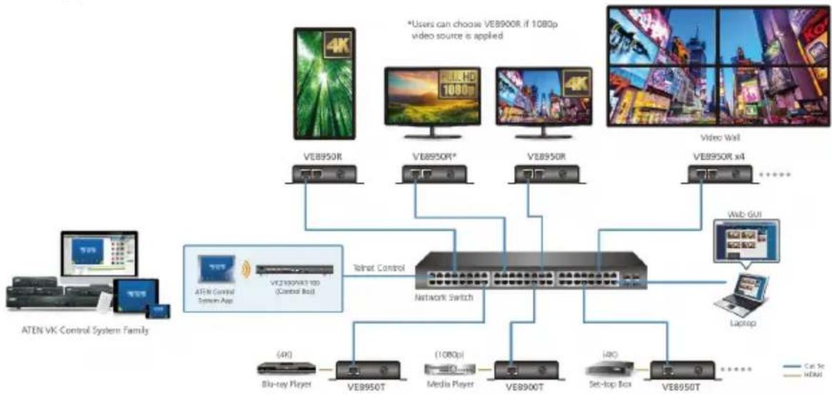
Collaboration with ATEN Control System
- Integrated solution – Compatible with ATEN Control System, allowing users to directly operate VE8900/8950 via CLI Telnet or RS-232 protocol
- Effortless operation – One click to effectively operate VE Manager, TV, projector, source player, and related equipments via touch panel and keypad
flowchart
graph TD
    A["ATEN VK Control System Family"] --> B["ATEN Control System App"]
    B --> C["VC2100V83100 (Control Box)"]
    C --> D["Telnet Control"]
    D --> E["Network Switch"]
    E --> F["(4K) Blu-ray Player"]
    E --> G["(108p) Media Player"]
    E --> H["(4K) Set-top Box"]
    E --> I["(4K) Web GUI"]
    E --> J["(4K) Laptop"]
    K["VEB950R"] --> L["4K"]
    M["VEB950R*"] --> N["108p HD"]
    O["VEB950R"] --> P["4K"]
    Q["VEB950R x4"] --> R["......"]
    S["Video Wall"] --> T["......"]
    U["ATEN VK Control System Family"] --> V["ATEN VK Control System App"]
    V --> W["VC2100V83100 (Control Box)"]
    W --> X["Telnet Control"]
    X --> Y["Network Switch"]
    Y --> Z["(4K) Blu-ray Player"]
    Y --> AA["(108p) Media Player"]
    Y --> AB["(4K) Set-top Box"]
    Y --> AC["(4K) Web GUI"]
Spontaneous Scheduling Management
- Offers an user-friendly scheduling management function for users to pre-plan the display schedule
- Provides robust and intuitive scheduling management options to help users to manage all events in the calendar to as detailed as to setting events to minute intervals.
- Integrates all VE89 units to arrange the profile by grouping individual receiver or video wall
- Multiple profiles can be arranged to play in any order over a selected period of time
No Complicated IP Setup
- Simple configuration that requires no extensive IT experience or extra learning
◆ Effortlessly switches among input sources via top panel pushbuttons
Web GUI-Based Management, No Additional Server PCs or Software Required
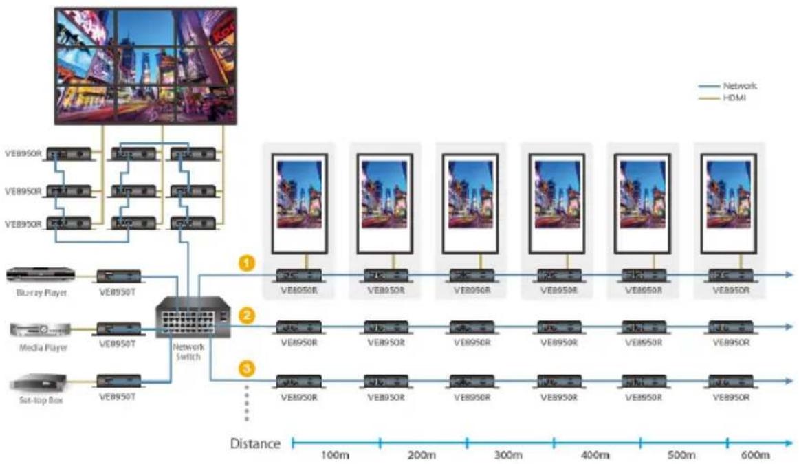
- Simple Access – Without typing IP address on Chrome browser, users are allowed to directly link to VE Manager via one click on “Find My VE” Chrome based free tool
Go Further For Less with Daisy Chaining
- Connects multiple displays through a single port to utilize every port of the network switch and maximize their value
- Easily expandable – cabling and system deployment is easy with no huge network switches and fewer cables needed
- Perfect for large-scale deployment covering hundreds of meters, such as hotel facilities, airports, university campuses, stations, shopping malls, and exhibition centers
Note: Depending on your network architecture, we recommend daisy chaining up to 30 units. Please contact ATEN representatives for more details.
flowchart
graph TD
    subgraph Network
        A["VEB950R"] --> B["Blurry Player"]
        C["VEB950R"] --> D["Media Player"]
        E["VEB950R"] --> F["Set-top Box"]
    end

    subgraph HDMI
        G["VEB950R"] --> H["VEB950T"]
        I["VEB950R"] --> J["VEB950T"]
        K["VEB950R"] --> L["VEB950T"]
    end

    M["Network Switch"] --> N["VEB950R"]
    M --> O["VEB950T"]
    M --> P["VEB950R"]
    M --> Q["VEB950T"]
    M --> R["VEB950R"]
    M --> S["VEB950T"]
    M --> T["VEB950R"]
    M --> U["VEB950T"]
    M --> V["VEB950R"]
    M --> W["VEB950T"]
    M --> X["VEB950R"]
    M --> Y["VEB950T"]
    M --> Z["VEB950R"]
    M --> AA["VEB950T"]
    M --> AB["VEB950R"]
    M --> AC["VEB950T"]
    M --> AD["VEB950R"]
    M --> AE["VEB950T"]
    M --> AF["VEB950R"]
    M --> AG["VEB950T"]
    M --> AH["VEB950R"]
    M --> AI["VEB950T"]
    M --> AJ["VEB950R"]
    M --> AK["VEB950T"]
    M --> AL["VEB950R"]
    M --> AM["VEB950T"]
    M --> AN["VEB950R"]
    M --> AO["VEB950T"]
    M --> AP["VEB950R"]
    M --> AQ["VEB950T"]
    M --> AR["VEB950R"]
    M --> AS["VEB950T"]
    M --> AT["VEB950R"]
    M --> AU["VEB950T"]
    M --> AV["VEB950R"]
    M --> AW["VEB950T"]
    M --> AX["VEB950R"]
    M --> AY["VEB950T"]
    M --> AZ["VEB950R"]
    M --> BA["VEB950T"]
    M --> BB["VEB950R"]
    M --> BC["VEB950T"]
    M --> BD["VEB950R"]
    M --> BE["VEB950T"]
    M --> BF["VEB950R"]
    M --> BG["VEB950T"]
    M --> BH["VEB950R"]
    M --> BI["VEB950T"]
    M --> BJ["VEB950R"]
    M --> BK["VEB950T"]
    M --> BL["VEB950R"]
    M --> BM["VEB950T"]
    M --> BN["VEB950R"]
    M --> BO["VEB950T"]
    M --> BP["VEB950R"]
    M --> BQ["VEB950T"]
    M --> BR["VEB950R"]
    M --> BS["VEB950T"]
    M --> BT["VEB950R"]
    M --> BU["VEB950T"]
    M --> BV["VEB950R"]
    M --> BW["VEB950T"]
    M --> BX["VEB950R"]
    M --> BY["VEB950T"]
    M --> BZ["VEB950R"]
    M --> CA["VEB950T"]
    M --> CB["VEB950R"]
    M --> CC["VEB950T"]
    M --> CD["VEB950R"]
    M --> CE["VEB950T"]
    M --> CF["VEB950R"]
    M --> CG["VEB950T"]
    M --> CH["VEB950R"]
    M --> CI["VEB950T"]
    M --> CJ["VEB950R"]
    M --> CK["VEB950T"]
    M --> CL["VEB950R"]
    M --> CM["VEB950T"]
    M --> CN["VEB950R"]
    M --> CO["VEB950T"]
    M --> CP["VEB950R"]
    M --> CQ["VEB950T"]
Use daisy chains to configure a video wall or expand the AV system hundreds of meters
Video Wall Support
◆ Supports up to 8 x 8 video wall (64 displays)
◆ Supports horizontal or vertical (90° and 270° rotation) display orientation
- Easily switches layout profiles, preview and drag-and-drop video sources via the intuitive web GUI
Note: If you experience issues related to your network architecture, please contact ATEN representatives for support.
Embedded / De-embedded Audio Support
- For VE8900T / VE8950T – separate audio signal can be embedded into the HDMI stream
- For VE8900R / VE8950R – audio stream can be extracted from the HDMI stream and delivered as a separate audio signal
Multiple Control Channels
- Multiple control methods – the system can be managed via Ethernet or top-panel pushbuttons
- USB Connectivity – USB port (USB 2.0) allows for connection of devices such as keyboard, mouse, flash drive, printer, and other USB peripherals*
- Bi-directional IR Channel – IR transmission is processed one way at a time
- RS-232 Channel – bi-directional RS-232 serial port allows for connection of peripherals such as touch screens and bar code scanners
Note: Each VE8900/8950 transmitter can be controlled by a total of 4 USB touch screens installed to VE8900/8950 receivers.
Getting Started Tasks
Follow the steps below to install, connect, configure, and getting started with your VE8900 / VE8950 devices.
- Decide your network architecture and configuration. For more information, see the Implementation Guide.
-
Mount your VE8900 / VE8950 devices on walls or racks. For more information, see Mounting the VE8900 / VE8950 Device, page 10.
-
Connect the VE8900 / VE8950 devices to sources, displays, network, and other hardware devices as required. For more information, see Connecting VE8900 / VE8950, page 11.
-
Use one of the following methods to assign input sources.
Note: Skip this step if you have a point-to-point setup. In a point-to-point setup, source input is automatically assigned.
- Assign input sources using the device panel.
For more information, see Assigning Sources Using the Device Panel, page 18. - Assign input sources using VE Manager.
For more information, see Logging In and Configuring VE Manager, page 25 and Find My VE Extension, page 21.
Chapter 2
Hardware Setup

Before you proceed to hardware setup:
-
Please review the safety information regarding the placement of this device in Safety Instructions, page 89.
-
Do not power on the VE8900 / VE8950 device until all the necessary hardware is connected.
Components
VE8900T / VE8950T Front View
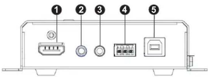
| No. | Component Function | |
| 1 | HDMI In Connects an HDMI | cable from the source device. |
| 2 | Audio Jack Connects to an | analog audio player from the source device. Note that microphones are not supported. |
| 3 | IR Port Connects to an IR | receiver/transmitter to allow for configuration using a remote control. |
| 4 | RS-232 Terminal Block Connects to a computer for serial control. | |
| 5 | USB Type-B Connects to a virtual media or a USB peripheral device. | |
VE8900T / VE8950T Rear View
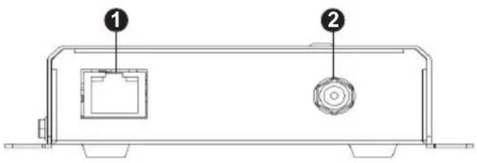
| No. | Component Function |
| 1 LAN | Port Connects the unit to LAN with a network cable. |
| 2 Power | Jack Connects to the DC power adapter to provide power to the unit. |
VE8900R / VE8950R Front View
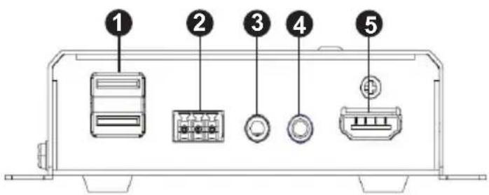
| No. | Component Function | |
| 1 | USB Type-A Connects to virtual media or a USB peripheral device. | |
| 2 | RS-232 Terminal Block Connects to a serial device. | |
| 3 | Audio Jack Connects to a speaker from the output device. | |
| 4 | IR Port Connects to an IR receiver/transmitter to allow for configuration using a remote control. | |
| 5 | HDMI Out Connects to an HDMI cable from the output device. | |
VE8900R / VE8950R Rear View
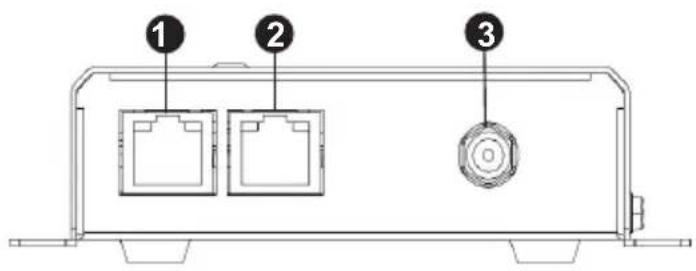
| No. | Component Function | |
| 1 | LAN 1 Port Connects the unit to LAN with a network cable. | |
| 2 | LAN 2 Port Connects to another VE8900R / VE8950R with a network cable in a daisy-chain setup. | |
| 3 | Power Jack | Connects to the DC power adapter to provide power to the unit. |
Mounting the VE8900 / VE8950 Device
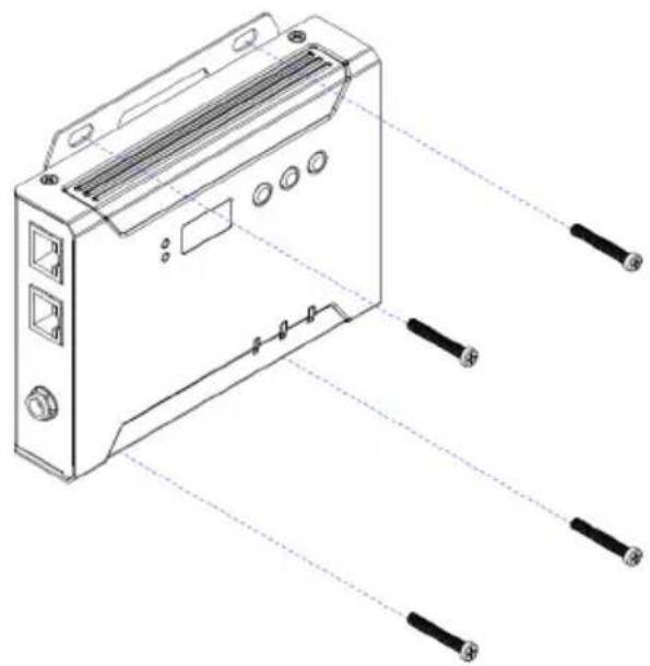
Wall Mount
Secure or hang the VE8900 / VE8950 device to the wall using the built-in brackets.
natural_image
Technical line drawing of a device rear panel with connectors and ports (no text or symbols)Rack Mount
Use the VE-RMK1U Rack Mount Kit to rack-mount the VE8900 / VE8950. For more information about this accessory, go to www.aten.com/products
Connecting VE8900 / VE8950
Follow the steps below to connect your VE8900 / VE8950 devices with the hardware as required.
Note:
- For details on LED indicators to help you identify statuses of connection or signal transmission, see Status LEDs, page 15.
- For a list of compatible ATEN products, visit the VE8900 / VE8950 product web page at www.aten.com
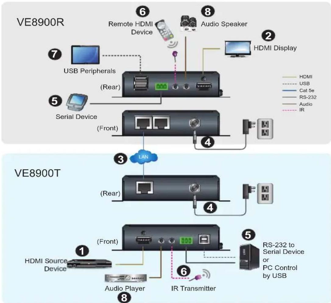
flowchart
graph TD
    subgraph_VE8900R["VE8900R"]
        A["USB Peripherals"] --> B["(Rear)"]
        C["Remote HDMI Device"] --> D["Audio Speaker"]
        E["Serial Device"] --> F["(Front)"]
        G["HDMI Display"] --> H["+"]
        I["HDMI"] --> J["USB"]
        K["Cat 5e"] --> L["RS-232"]
        M["Audio"] --> N["IR"]
    end
    subgraph_VE8900T["VE8900T"]
        O["LAN"] --> P["(Rear)"]
        Q["HDMI Source Device"] --> R["(Front)"]
        S["Audio Player"] --> T["IR Transmitter"]
        U["RS-232 to Serial Device or PC Control by USB"] --> V["+"]
    end
- Connect the HDMI In port on the VE8900T / VE8950T device to the HDMI Out port on your video source device using an HDMI cable.
- Connect the HDMI Out port on the VE8900R / VE8950R device to the HDMI In port on your display device using an HDMI cable.
- Depending on your deployment type, connect your VE8900T / VE8950T and VE8900R / VE8950R to the same LAN.
- Point-to-point deployment: directly connect the LAN 1 Ports of your VE8900T / VE8950T and VE8900R / VE8950R with an RJ-45 cable.
- Splitter and matrix deployment: connect the LAN 1 Ports of your VE8900T / VE8950T and VE8900R / VE8950R to the same network switch with RJ-45 cables.
- Plug the Power Adapter into the Power Jack on the VE8900T / VE8950T and VE8900R / VE8950R devices.
- (Optional) Connect an RS-232 serial device or peripheral to the RS-232 Terminal Block on your VE8900R / VE8950R device. This device can be a computer, a touch screen, a bar code scanner, or a control system. ^[1]
- (Optional) Connect an IR transmitter/receiver cable to the IR Ports of your VE8900T / VE8950T and VE8900R / VE8950R devices. [1]
- (Optional) Connect USB peripherals to the USB ports on your VE8900T / VE8950T and VE8900R / VE8950R devices. [1] [2]
- (Optional) Connect an audio device to the VE8900R / VE8950R Audio Jack. ^[3]
Note:
- The IR, RS-232, and USB signal transmissions are disabled by default. To enable the functions, go to System Settings > Receiver > IR/RS232 or USB in VE Manager and select the signal source.
- Each VE8900 / VE8950 transmitter can be controlled by a total of 4 USB touch screens installed to VE8900 / VE8950 receivers.
- To receive HDMI audio on the VE8900 / VE8950 transmitter, make sure to configure the following in VE Manager:
- Set the transmitter to receive HDMI audio:
Go to System Settings > Transmitter > Audio In in VE Manager and change the setting to HDMI.
- To allow for 5.1 or 7.1 surround sound on a VE8900 / VE8950 receiver, do the following:
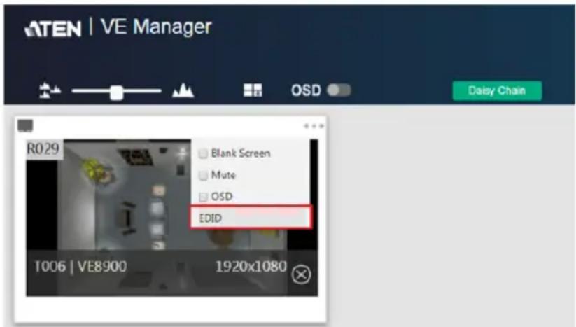
a) In VE Manager, go to System Settings > Transmitter, access the configuration window for the corresponding transmitter, and then set EDID to Manual.
b) From the VE Manager's preview area, click on the ... icon and select EDID to allow transmission of the receiver's EDID to the transmitter.
This Page Intentionally Left Blank
Chapter 3
Panel Operation
Overview
This chapter provides information on panel LEDs and instructions to operate the VE8900 / VE8950 using the panel buttons.
Status LEDs
Both the VE8900 / VE8950 Transmitter and Receiver have front panel LEDs to indicate their operating and power status.
| LED Indication Description | ||
| Power Lights green | The device is powered on. | |
| Off Power is off. | ||
| LINK Lights orange | LAN is connected. | |
| Off LAN is not connected. | ||
| HDMI Out Lights or | ange The video output is stable. | |
| Blinks orange The video output is unstable. | ||
| Off The video output is not transmitted. | ||
| RJ-45 Connector (Left LED) | Lights orange Data is being transmitted at 100Mpbs. | |
| Lights green Data is being transmitted at 1Gpbs. | ||
| RJ-45 Connector (Right LED) | Lights green LAN is connected and no data is being transmitted. | |
| Blinks green LAN is connected and data is being transmitted. | ||
Note: The HDMI Out LED is only available on VE8900 / VE8950 receivers.
Panel Controls
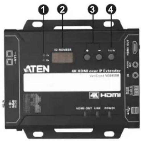
VE8950 Receiver
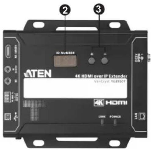
VE8950 Transmitter
| No. | Name Description | |
| 1. | Tx/Rx LEDs Lights to indicate whether the displayed ID number is of Tx or Rx. | |
| 2. | ID Number | Transmitter side: Identifies its ID number.Receiver side:Identifies its ID number or the transmitter's ID number when the panel control is switched to Tx.If the ID number exceeds 3 digits, letter A, b, c, d, E, and F are used to replace the first two digits.A= 10, A00 ~ A99 to display ID number 1000 ~ 1099.b= 11, b00 ~ b99 to display ID number 1100 ~ 1199.c= 12, c00 ~ c99 to display ID number 1200 ~ 1299.d= 13, d00 ~ d99 to display ID number 1300 ~ 1399.E= 14, E00 ~ E99 to display ID number 1400 ~ 1499.F= 15, F00 ~ F99 to display ID number 1500 ~ 1599.An ID Number blinks to indicate that it is been used by another VE8900 / VE8950 device. |
| 3. Up (+) / Down (-) Buttons | ♦ Assign ID numbers on VE8900 / VE8950 devices.♦ Assign the source video (transmitter) for the receiver | |
| 4. Tx/Rx Switch Button Press to switch control between a receiver and its corresponding transmitter. | ||
Note:
- The VE8900 / VE8950 device automatically locks its panel when it idles for 1 minute. To unlock the panel, press and hold the Down (-) button for 3 seconds.
- Tx/Rx LEDs and Tx/Rx Switch Button are only available on VE8900 / VE8950 receivers.
Assigning Sources Using the Device Panel
- Assign an ID number to each of your VE8900R / VE8950R devices.
a) On a VE8900R / VE8950R device, make sure the control is switched to Rx, in which case the Rx LED lights up. If not, press the Tx/Rx switch button.
b) Use the Up (+) and Down (-) buttons to assign an ID number to this receiver.
c) Repeat steps 1 (a) and 1 (b) on each of your VE8900R / VE8950R devices.
- For a matrix setup, assign an ID number to each of your VE8900T / VE8950T devices.
a) On a VE8900T / VE8950T device, use the Up (+) and Down (-) buttons to assign an ID number to this transmitter.
b) Repeat step 2 (a) on each of your VE8900T / VE8950T devices.
- Assign source inputs to your VE8900R / VE8950R devices.
a) On a VE8900R / VE8950R device, press the Tx/Rx switch button to switch the control to Tx, in which case the Tx LED lights up.
b) Use the Up (+) and Down (-) buttons to assign a source input to this receiver.
c) Repeat steps 3 (a) and 3 (b) on each of your VE8900R / VE8950R devices.
Chapter 4
Management
Overview
ATEN VE8900 / VE8950 HDMI over IP Video Extenders can be remotely and centrally managed using a built-in utility program, the ATEN VE Manager. Accessed through a web browser, this utility provides a central platform that allows you to do the following:
| Feature Details | |
| Configure transmitter and receiver settings | See Transmitter Settings, page 49 and Receiver Settings, page 51. |
| Monitor transmitter and receiver statuses | See Checking VE8900 / VE8950 Statuses, page 46. |
| Create display templates | See Creating a Video Wall Layout, page 34. |
Looking Up the Login IP Address
Follow the steps below to download IP Installer utility, and use the utility to look up the IP address of your VE8900 / VE8950 transmitter.
-
Go to the download link below:
https://www.aten.com/global/en/supportcenter/downloads/ -
Type in VE8900 in the field below “Download materials for other products” and press OK.
-
Scroll down the page and click either VE8900T or VE8900R.
-
Scroll down the page to find IP Installer zip file under “Software & Drivers”. Click the file to download.
-
Unzip and execute the downloaded IP Installer. The Network Device IP Installer screen appears.
-
Click Enumerate to search for ATEN devices in the network. The detected devices are shown in Device List.
-
Use the IP address of any VE8900 / VE8950 transmitter to log in VE Manager.
Find My VE Extension
Chrome browser offers an extension called "Find My VE" for quick access to VE Manager login page.
- For the extension application, go to the download link: https://www.aten.com/global/en/supportcenter/downloads/
- Type in VE8900 in the field below “Download materials for other products” and press OK.
- Scroll down the page and click either VE8900T or VE8900R.
- Scroll down the page to find VE Browser zip file under "Software & Drivers". Click the file to download.
- Unzip and execute the downloaded VE Browser using Chrome.
- After installing the extension, you may find it in Chrome's extension page as shown in the example below:
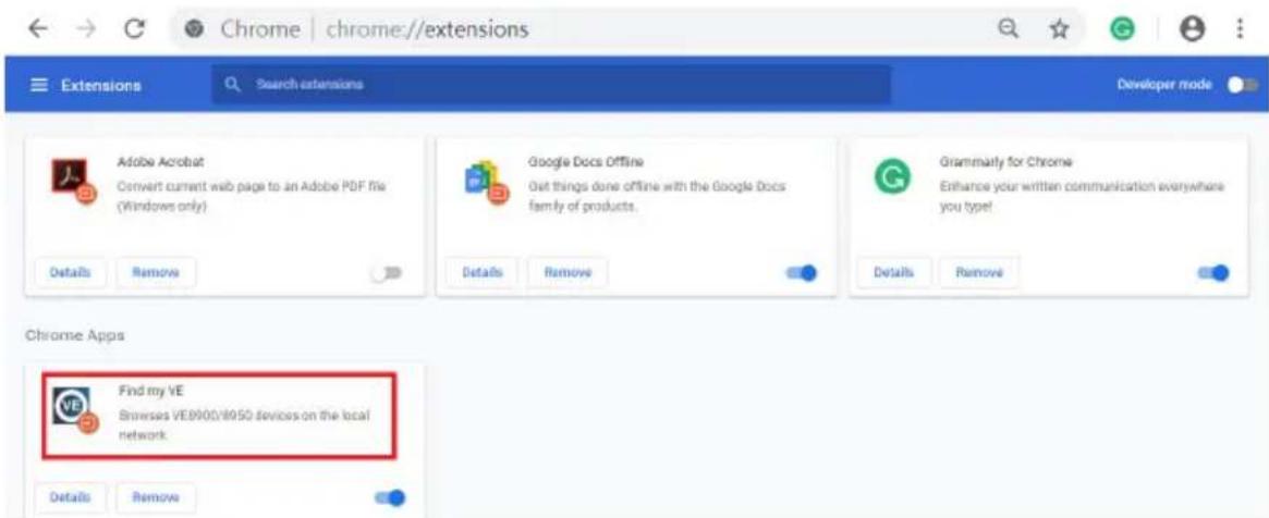
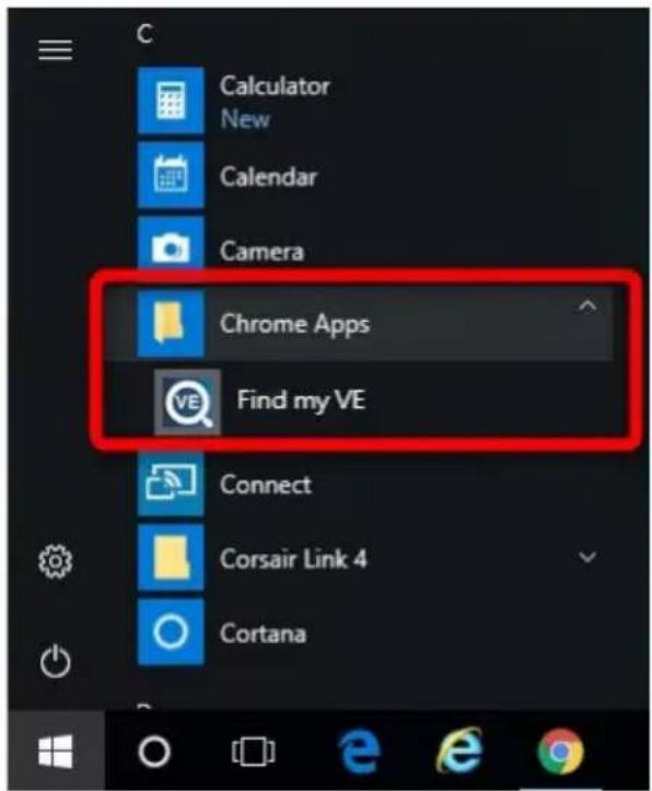
If you have it installed, you can get the extension application out in the start menu as shown in the example below:
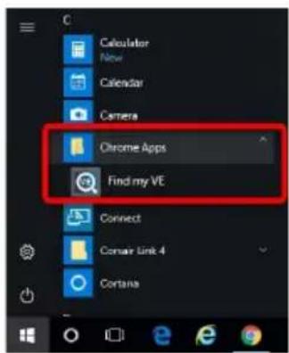
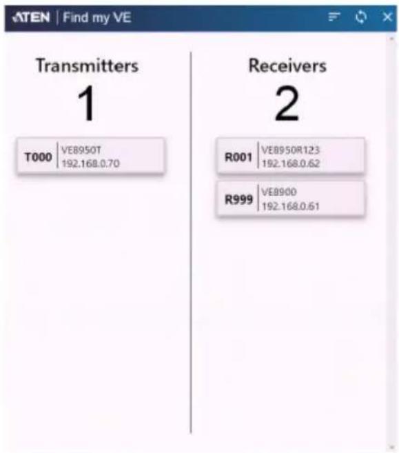
Clicking the extension application will bring up a window as shown below:
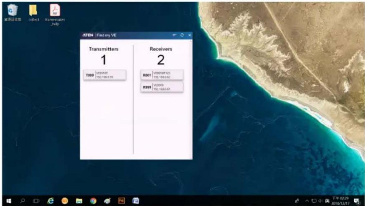
The window will display all the units within the network as a list.
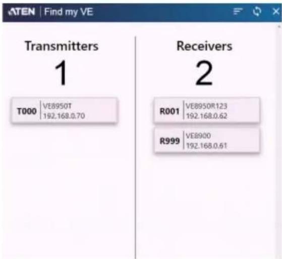
Click the icon (top right-hand corner) to refresh the list.
Use the scroll bar on the right to scroll through the list.
Use the icon (top right-hand corner) to determine way the list is ordered. Click the icon to toggle between “By Name”, “By Id” and “By IP”, and the selected way is in bold character. For example, in the diagram above, the ID of the devices are in bold, which indicates that “By ID” is selected.
Click the bar of any of the shown devices to go to VE Manager.
Click "Close" to close the VE Browser application.
Start VE Manager using Find My VE Extension
You can go directly into VE Manager login page using the Find My VE Extension. To do so, follow the steps below:
- In the Windows Start menu, click to select Find My VE.
- In the Find My VE window, click the bar of any of the shown devices and the system will open the VE Manager login page.
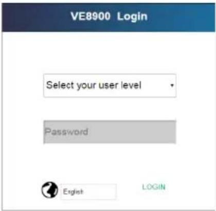
Please refer to Logging In and Configuring VE Manager on page 25 for information about logging in.
Logging In and Configuring VE Manager
On a computer with web access, follow the steps below to log in VE Manager.
- Open a web browser and type the IP address you obtained using IP Installer Utility. This screen appears.
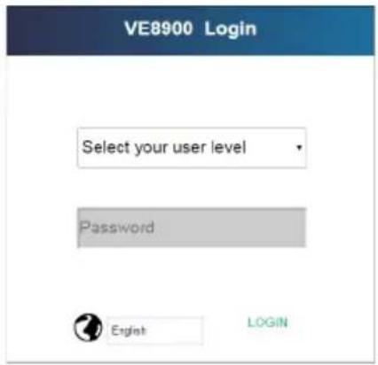
- Select Administrator for User Level and type password for the Password field. This screen appears upon first login.
Note: If you are the administrator, and are logging in for the first time, use the default Password: password. For security purposes, the system will prompt you to change the login password. The password must be different from your login password
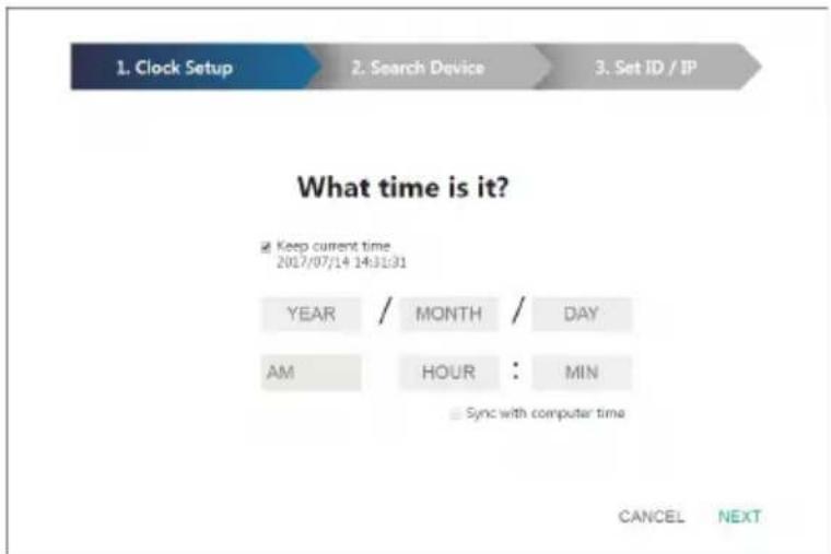
- Specify a date and time for the VE Manager using one of the following methods:
- To keep the current date and time settings, select Keep current time.
- To adopt the date and time settings of the endpoint used to access VE Manager, select Sync with computer time.
- To specify a different date and time, type the desired date and time. Make sure the date is typed in this format: YYYY/MM/DD.
- Click NEXT. This screen appears. The setup wizard lists the VE8900 / VE8950 transmitters and receivers found in the network.
![1. Clock Setup 2. Search Device 3. Set ID / IP Transmitters 2 ✓ [T001] 00-10-74-be-00-50 ✓ [T002] 00-10-74-be-00-40 Receivers 4 ✓ [R001] 00-10-74-b9-00-80 ✓ [R002] 00-10-74-b9-10-00 ✓ [R003] 00-10-74-b9-00-03 ✓ [R004] 00-10-74-b9-00-90 BACK NEXT](/content/2026/05/1005482/images/f58aebf66bd210c0feb110af2edddf8574aebebcd1a8b61bb8cd4eb1bb26b5a3.jpg)
- To configure device IP addresses, select the devices from the list, and then click Next. This screen appears.
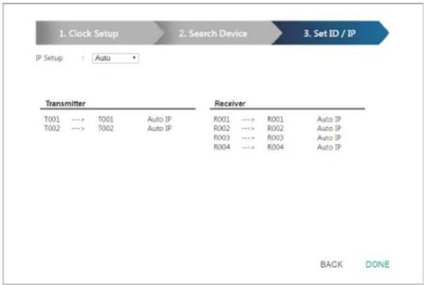
flowchart
graph LR
    A["1. Clock Setup"] --> B["2. Search Device"] --> C["3. Set ID / IP"]
    D["IP Setup"] --> E["Auto"]
    F["Transmitter"] --> G["Receiver"]
    H["T001"] --> I["Auto IP"]
    J["T002"] --> K["Auto IP"]
    L["R001"] --> M["Auto IP"]
    N["R002"] --> O["Auto IP"]
    P["R003"] --> Q["Auto IP"]
    R["R004"] --> S["Auto IP"]
    T["BACK"] --> U["DONE"]
- Click the IP Setup drop-down box to select a method for assigning IP addresses to the managed VE8900 / VE8950 devices.
- Auto: Select this option to have IP addresses automatically assigned by VE Manager.
- DHCP: Select this option to have IP addresses dynamically assigned by a DHCP server.
- Manual: Select this option to designate IP addresses for the managed video extenders. For details, see the step below.
- To manually assign IP addresses, follow the steps below.
a) From the Set ID / IP page, select Manual for IP Setup. This screen appears.
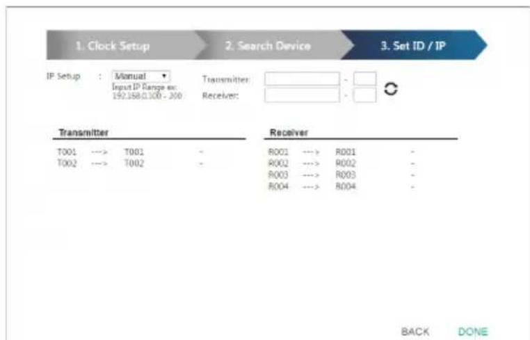
b) In the Transmitter and Receiver fields, type valid IP address ranges.
c) Click Refresh to start assigning IP addresses.
d) When the assignment is complete, VE Manager displays the assigned IP addresses.
- To re-assign device IDs, click and type a new ID for the target VE8900 / VE8950 device.
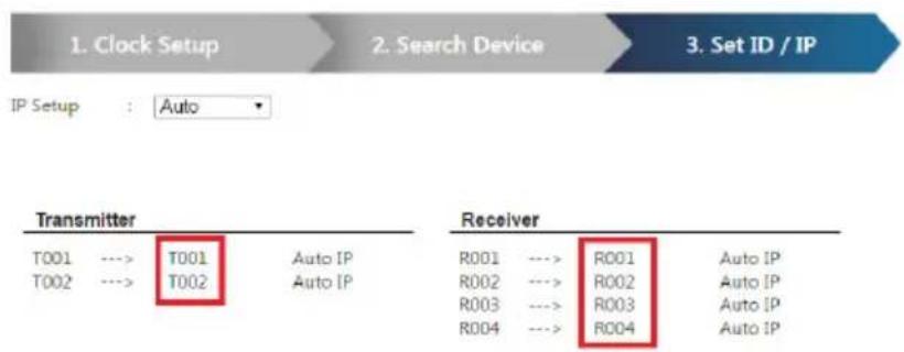
- Click Done. The VE Manager's main screen appears.
Note:
- For security reasons, ATEN recommends changing the password at first login. For details on account settings, see Account Settings, page 58.
- To access these settings again, click from the VE Manager's main screen, and then click
The Main Screen
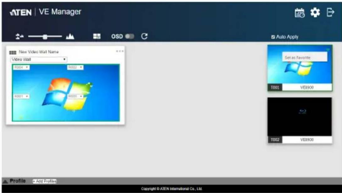
You can access the following controls from the VE Manager's main screen.
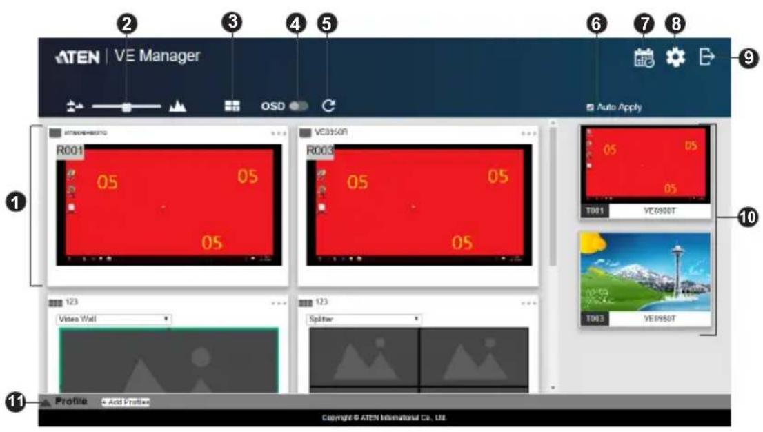
| No. | Component Description |
| 1 | Previews for Video Walls and Receivers Shows a preview of created video walls, individual video receivers, and daisy chain setups.♦ For details about creating video wall templates, see Creating a Video Wall Layout, page 34.♦ For details about controls in a preview, see Editing a Preview, page 37. |
| 2 | Preview Size Drag the slider bar to adjust the size of preview windows. |
| 3 | Create/Edit Video Wall Click to create [or edit] video wall templates. For details, see Assigning Sources Using VE Manager, page 30. |
| No. | Component | Description |
| 4 | OSD Globally enables | or disables panel control of the VE8900 / VE8950 devices used in managed video walls. To enable or disable panel control of VE8900 / VE8950 devices for a single video wall, use the OSD setting for a preview window. For details, seeConfiguration Menuin Editing a Preview, page 37. |
| 5 | Refresh Refresh / Update | the Daisy Chain Status. |
| 6 | Auto Apply Check to enable auto apply, where all the settings are automatically applied to the devices. | |
| 7 | Profile Schedule Click to enter profile scheduling page. For more information, please refer to Setup Profile Schedules on page 43. | |
| 8 | System Settings Click to access system settings, including the general settings, transmitter settings, receiver settings, firmware update, backup, and restore settings, and account settings. For more details, see Chapter 5, System Settings. | |
| 9 | Log Out Click to log out VE Manager. | |
| 10 | Source List Lists the display sources and identifies each source with its corresponding transmitter. | |
| 11 | Profile Bar Video wall profile for video wall display. For more information, please refer toProfileon page 38. | |
Apply / Auto Apply
If you wish to apply settings as you configure them, check Auto Apply.

Alternatively, if you wish to manually apply the settings, uncheck Auto Apply and use the Apply button. The button will light up to show a change was made.

Assigning Sources Using VE Manager
Follow the steps below to assign input sources using VE Manager.
-
On the main screen, identify the source you wish to be assigned in the "Source List" and the preview video walls / receivers.
-
Select and drag the source to the preview video walls / receivers.
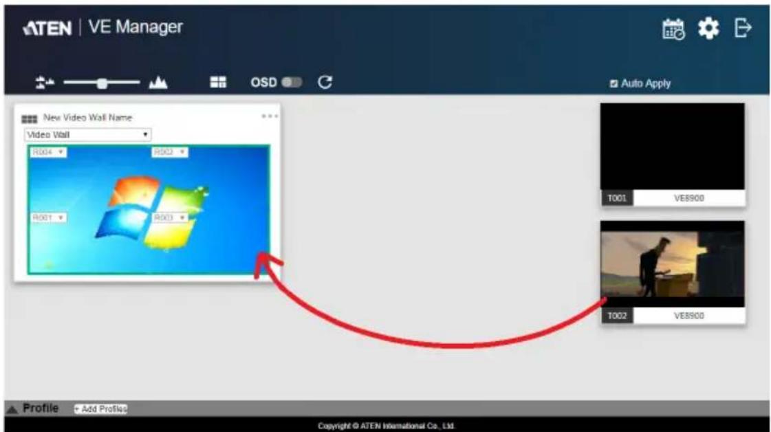
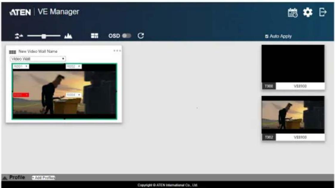
- When there is a display issue from the connected receiver, the specific receiver will be indicated in red from the preview.
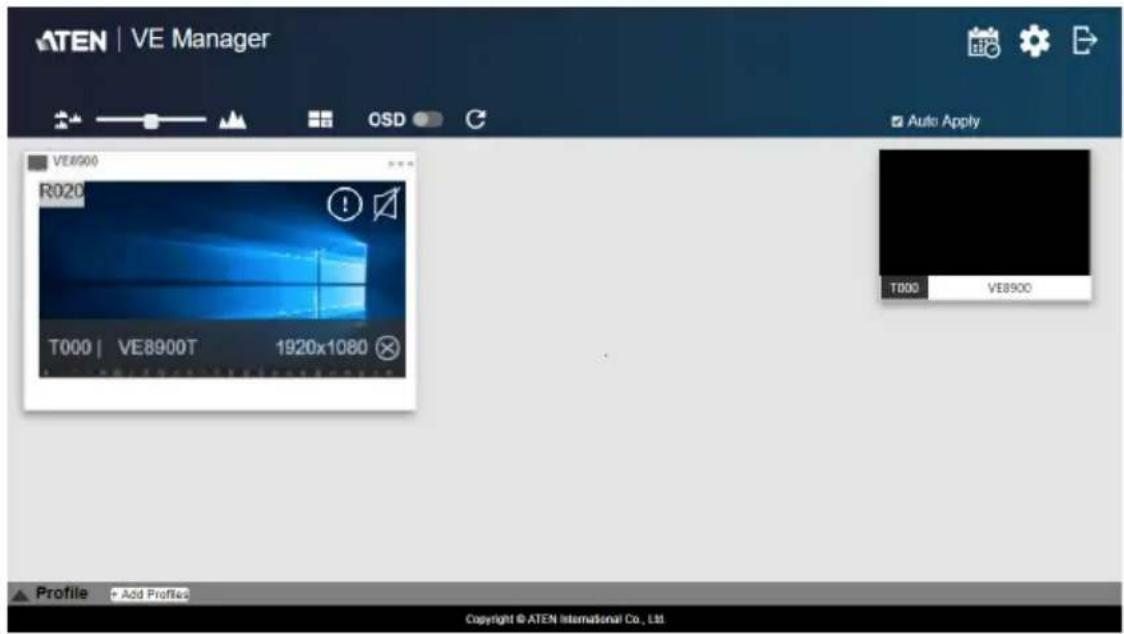
- When there is a display issue from a single connected receiver, the preview is shown below.
Alternatively, you can go into system settings to assign sources there. Follow the steps below:
- From the main screen, click 🔒, and then click the Receiver tab. The managed VE8900 / VE8950 receivers appear.
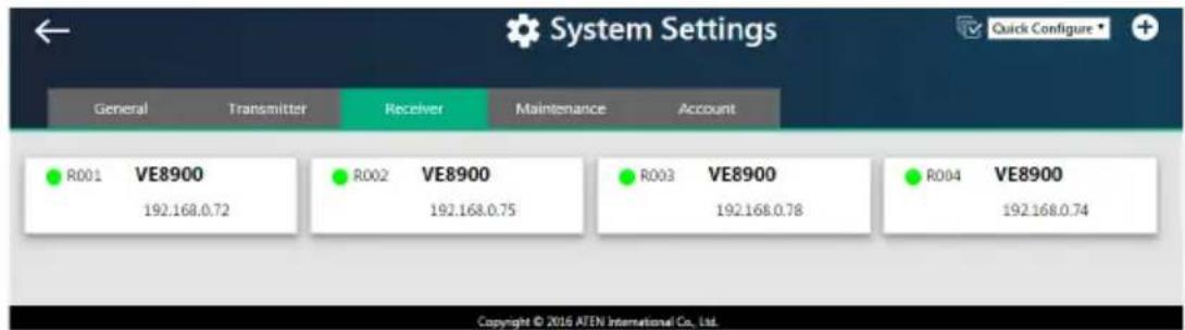
- Assign a source for each of the VE8900 / VE8950 receivers.
a) Move the cursor to a receiver. A green arrow appears at the top right corner of the receiver preview window.
b) Click the green arrow. A drop-down menu appears.
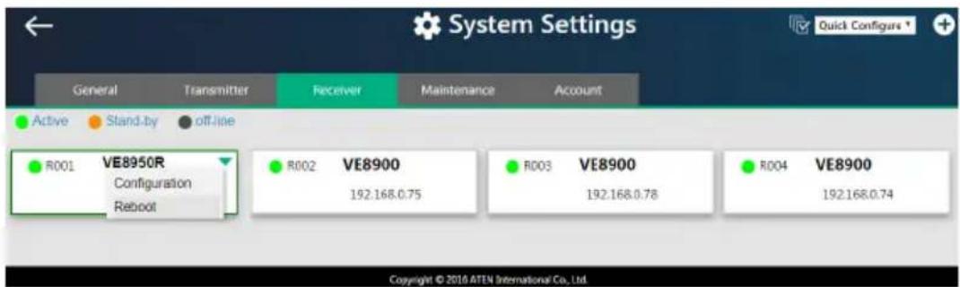
c) From the drop-down menu, click Configuration. This window appears.
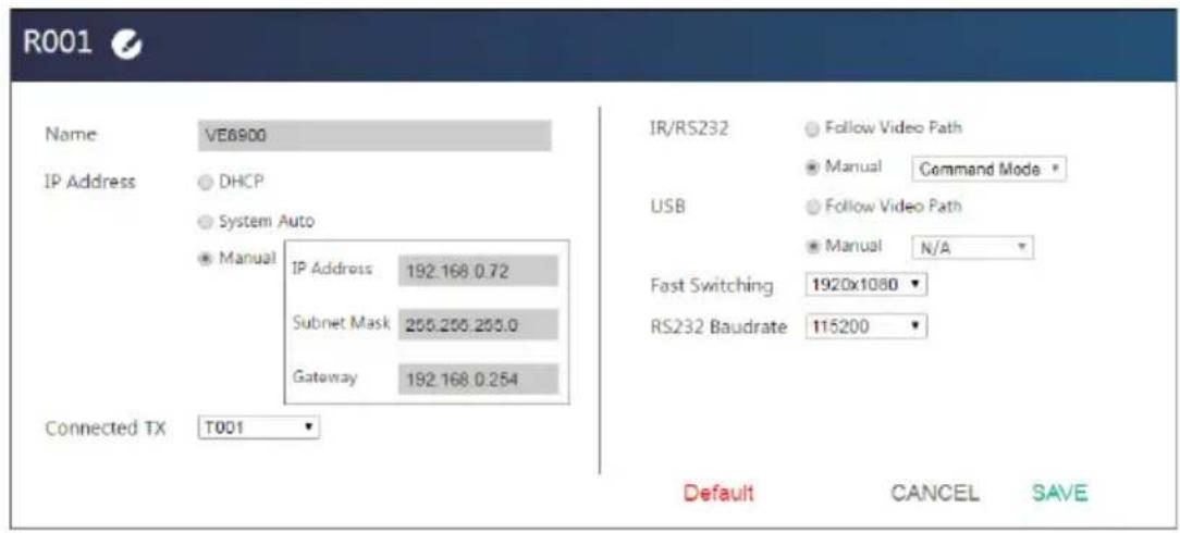
d) Click the Connected Tx drop-down arrow and select a Tx source.
e) Repeat steps 2 (a) to 2 (d) to assign sources for each of the receivers.
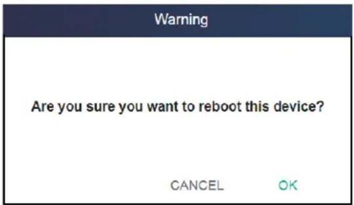
f) To reboot the VE8900 / VE8950, click the green arrow mentioned in step b), and click Reboot. This warning window appears.
Configuring and Setting Up a Video Wall
To configure a video wall, follow the steps below.
- Make sure you have created a video wall template for your specific needs. For detailed steps, see Creating a Video Wall Layout, page 34.
- From the VE Manager's main screen, drag and drop input sources from the Source List onto the created video wall layout. In the following example, the display source T002 is assigned to this video wall layout, which has four monitors, R001 to R004, merged to form an enlarged display of one source video.
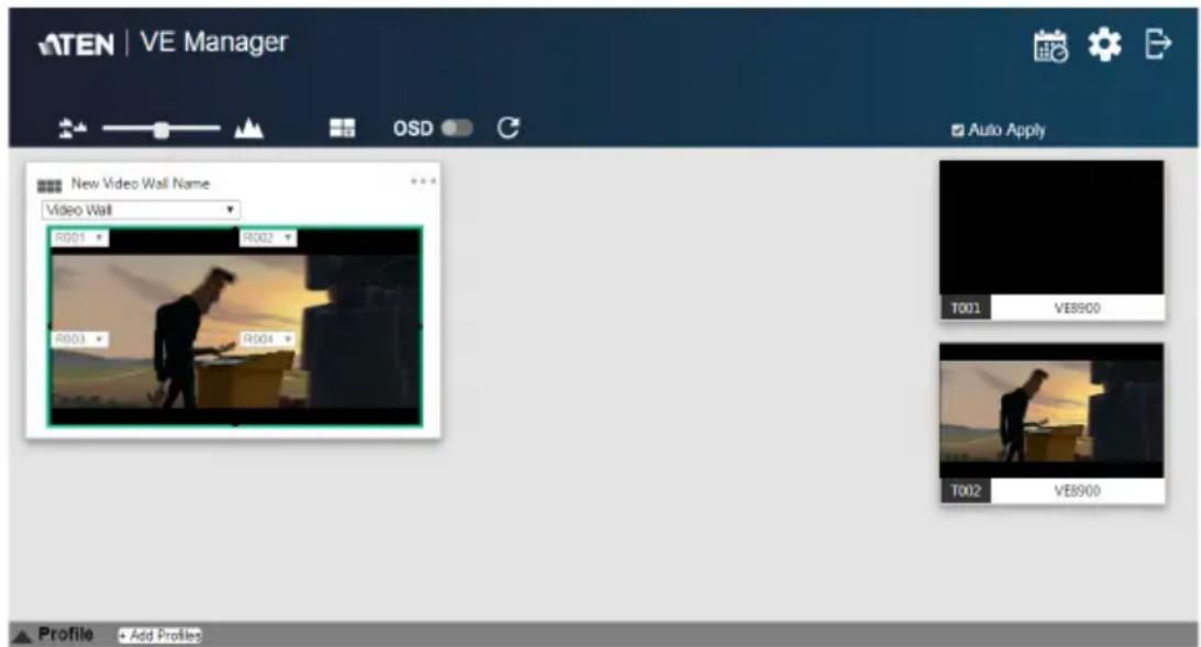
Note: For details on editing video wall settings, see Editing a Preview, page 37 and Editing a Preview, page 37.
Creating a Video Wall Layout
- To create a new layout, click Create/Edit Video Wall from the main screen. This window appears. A preview of the layout is shown in the middle.
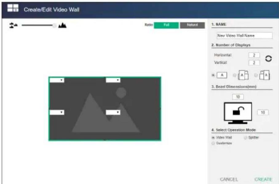
- Configure your video wall layout as required. Use the preview to help you visualize the layout.
| Control Description | |
| Name of Video Wall | Type to name this video wall. |
| Number of Displays | Define the following parameters.♦ Horizontal and Vertical: Click the drop-down boxes to select the number of displays for your video wall. Click Refresh to show a preview of your configuration.♦ Display orientation: Select horizontal or vertical display. A vertical display is either a 90° clockwise or a 90° counter-clockwise rotation of the horizontal display. |
| Bezel Dimensions | Type to specify the top/bottom and right/left widths of the monitor frame. The value on the top is the total of the top and bottom bezel, and the value on the right is the total of the left and right bezel. |
| Operation Mode Select an operation mode for your video wall. | |
| Video Wall: Select this option to set up a video wall.Splitter: Select this option to set up a display of identical content on multiple monitors.Customized: Select this option to create a customized display. Click New layout in the list to rename this template. | |
| Click and hold the slider bar to enlarge or reduce the size of preview windows. | |
| Use this button to merge displays. Click to select the desired monitors from the layout preview and click the button to merge the monitors. | |
| Use this button to separate already merged monitors. Select a merged monitor from the layout preview, and then click the button. | |
| Ratio Full Natural | Full: Click to display source videos in full extension.Natural: Click to displays source videos in their original aspect ratio. |
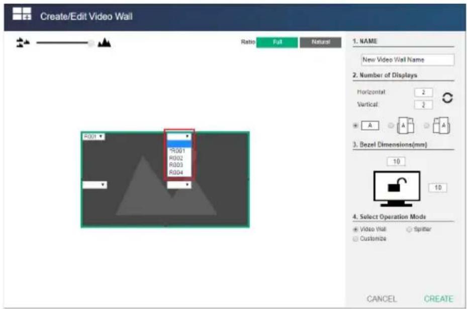
- From the preview area, click the drop-down boxes to define the output receiver for each monitor. An already selected, unavailable receiver is marked with an asterisk (*).
- Click CREATE. The new video wall template is created.
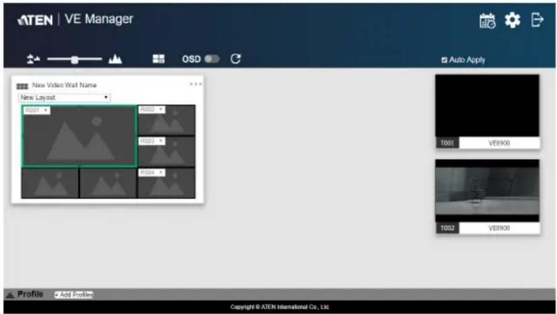
Editing a Video Wall Layout
To edit a video wall layout, from the VE Manager's main screen, click the top-right corner of the layout you wish to edit, and then select Edit. For more details on video wall settings, see Creating a Video Wall Layout, page 34.
Editing a Preview
You can edit the following settings for a video wall layout.
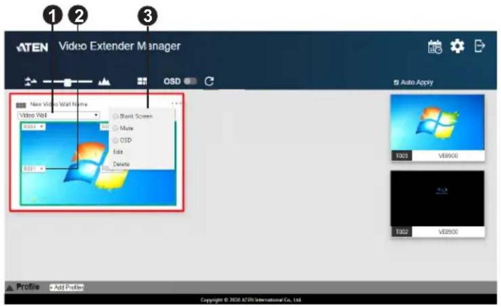
| No. | Control Description |
| 1 | Operation Mode Click the drop-down list to select an operation mode. |
| 2 | A s s i g Receiver Display the assigned receiver for the monitor.Tip: For an un-merged monitor, double-click the monitor to open up the settings page for the assigned receiver. |
| 3 | Configuration Menu Click the top-right corner to access the following controls:Blank: Disables the display on this video wall.Mute: Disables audio transmission to this video wall.OSD: Enables or disables the panel control of all VE8900 / VE8950 devices for this video wall.Edit: Click to access the video wall layout settings. For more details on video wall settings, see Creating a Video Wall Layout, page 34.Delete: Click to remove this layout from VE Manager. For a receiver, this option is only available when it is offline. |
Profile
After configuring video receiver / video wall settings, if you find that you would like to keep the current settings, you can save it as a profile. You can create different profiles and apply them manually, or you can set up profile schedules for switching video display at different times of a day, week or month.
Creating a Profile
Follow the steps below to create a profile.
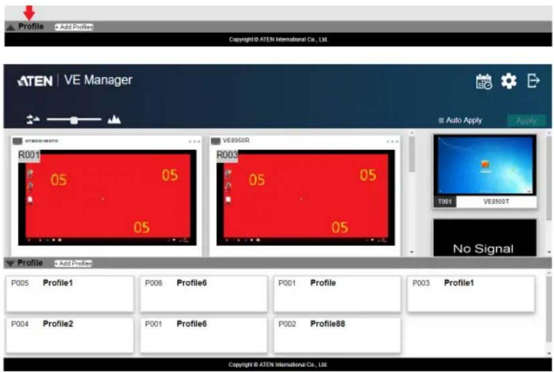
- On the main screen, click the profile arrow on the profile bar for the profile list shown below:
2. Click +Add Profiles for the page below:
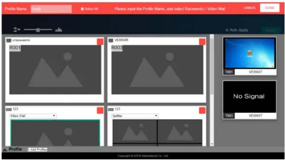
◆ Profile Name: Enter a profile name.
- Receivers / Video Walls: Select the receivers / video walls you wish to be in this profile by checking the orange box. Alternatively, you can select all receivers / video walls by checking the Select All option.
3. Click DONE to complete the configuration.
Edit, Delete and Disconnect Profile
On the profile list, you can edit, delete and disconnect profiles.
Click to select the profile you wish to configure and a green arrow will appear. Click the green arrow for a drop-down menu of edit, delete and disconnect options.
Edit
To edit the profile, click the Edit option:
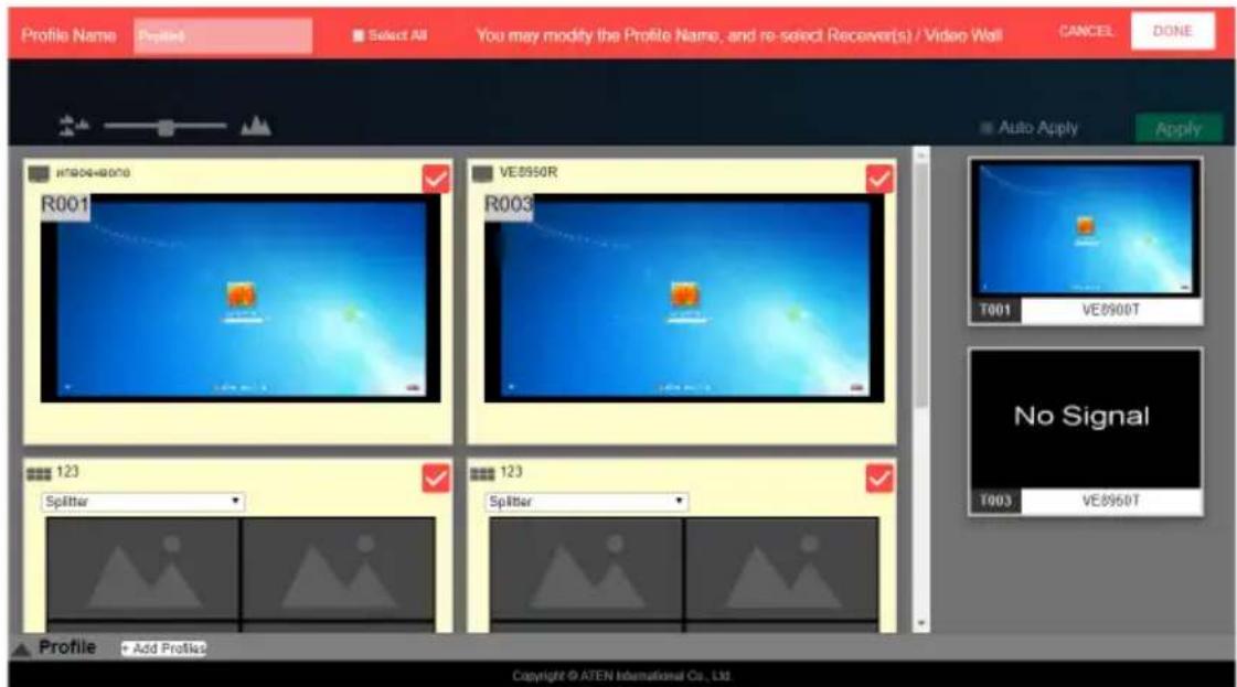
◆ Profile Name: Edit the profile name.
- Receivers / Video Walls: Select / de-select the receivers / video walls you wish to be in this profile by checking / unchecking the orange box. You can select / de-select all receivers / video walls by checking / unchecking the Select All option.
Click DONE to complete editing.
Delete
To delete a profile, click the Delete option:
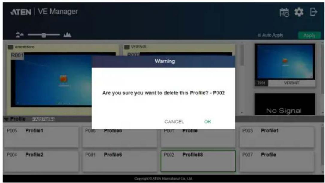
The system will ask if you would like to delete this profile. Click OK to proceed or click CANCEL to cancel.
Disconnect
To disconnect the current profile from the video wall, click Disconnect. The video wall should go blank.
Select / Apply Profile
After creating the profile, you can apply the settings of the profile to the video displays. Follow the steps below to apply the settings:
-
Bring up the profile list.
-
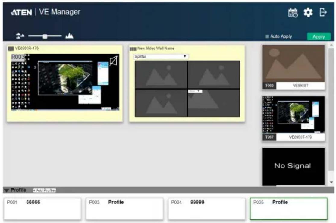
Click to select a profile and a preview will be shown:
Copyright © ATEN International Co., Ltd.
The video receiver / video wall selected in the profile will be displayed. If the current video receivers / video walls show yellow background, it indicates that the video settings have not been applied. If the background is grey, it indicates that the video receivers / walls are not available. If the background is white, it indicates that the settings are currently applied to the system.
- Click Apply to apply the settings of the profile.
- When applied, the video settings will be shown on the main screen.
Setup Profile Schedules
Follow the steps below to setup profile schedules.
- On the main screen, click the profile schedule icon on the top right hand corner.
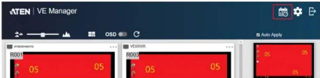
An example of profile schedule screen (with nothing planned) is shown below:
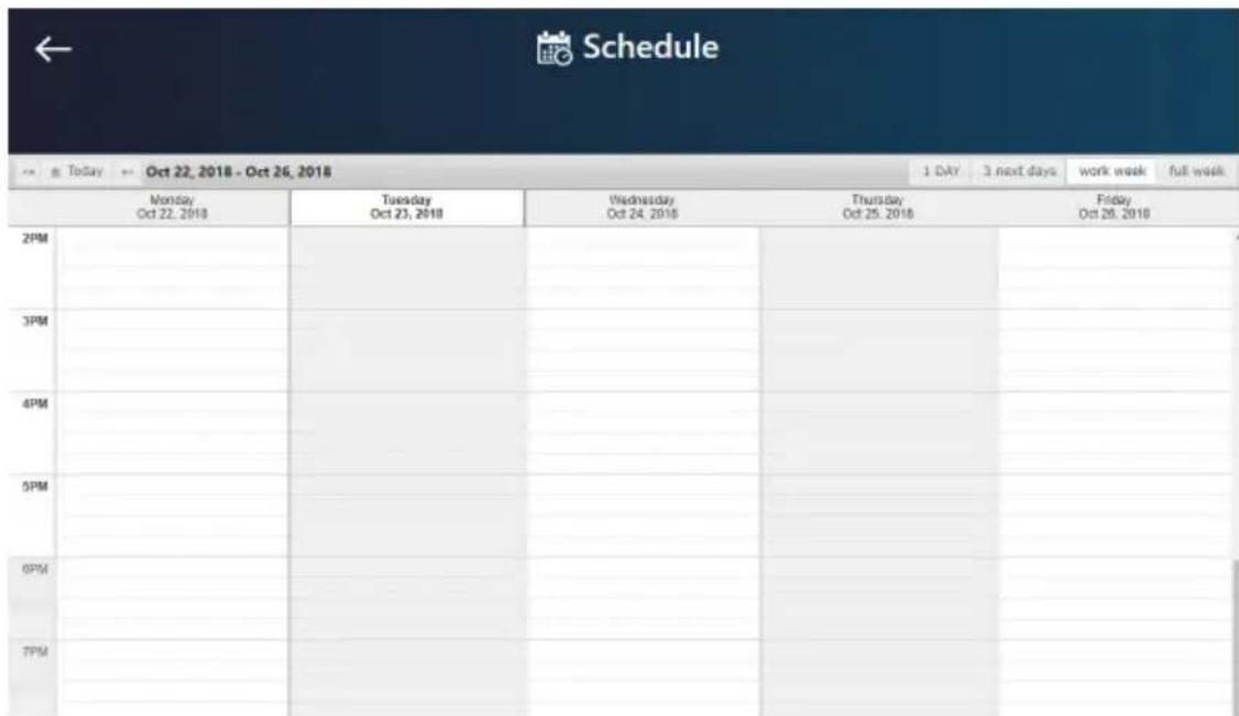
On this page, you can select to show current schedule of either “1 DAY”, “3 next days”, “work week” or “full week”.
- Click to select the day and time period to setup the schedule. An example is shown below:
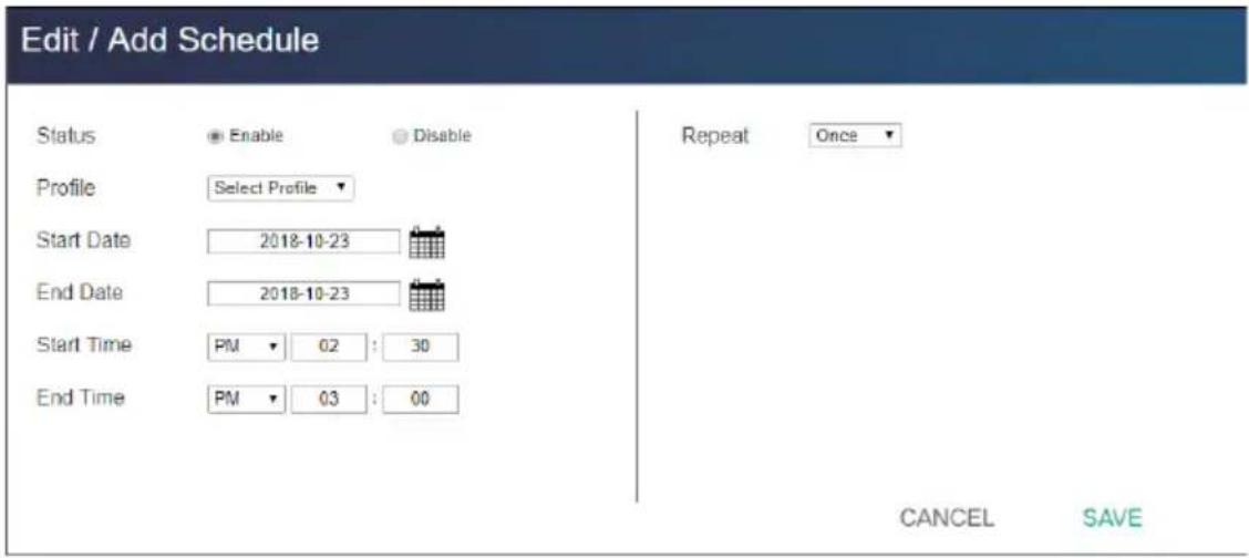
- Edit / Add the schedule as required:
◆ Status: Enable or disable the schedule.
◆ Profile: Select a profile.
- Start Date: Select or enter a start date.
◆ End Date: Select or enter an end date.
- Start Time: Select or enter a start time.
◆ End Time: Select or enter an end time.
- Repeat: Select a repeat cycle for the schedule.
Once: Select this option to run this schedule only once.
Daily: Select this option to run this schedule everyday.
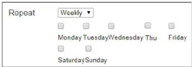
- Weekly: Select this option to run this schedule every week. You can also select which days you wish the schedule to run in a week. The option is shown below:
- Monthly: Select this option to run this schedule every month. you can also enter the days you wish the schedule to run in a month, or enter a range(s) for the schedule to run. Follow the on-screen instruction on how to enter the schedule here.
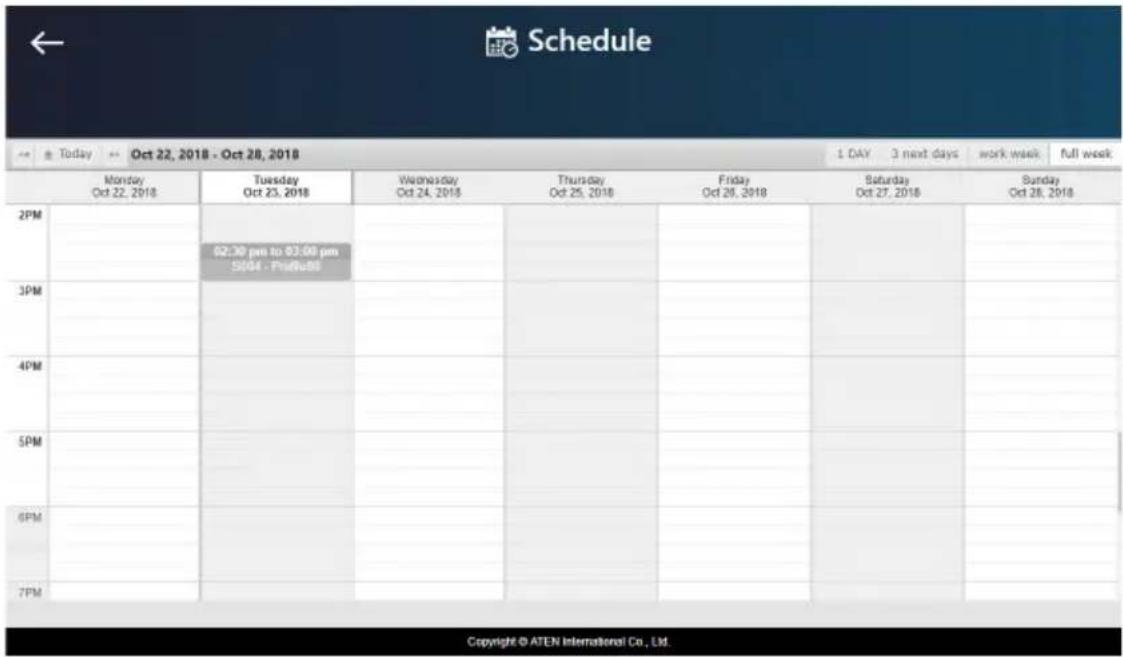
- Click SAVE to save the schedule and an example is shown below:
Managing VE8900 / VE8950 Devices
Checking VE8900 / VE8950 Statuses
You can check the statuses of your VE8900 / VE8950 devices using by clicking ⚙ from the main screen, and then the Transmitter or Receiver tab.
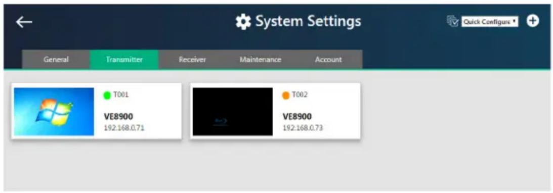
The status for a VE8900 / VE8950 device is indicated with a colored circle. See the table below for status indicators and the corresponding descriptions.
| Indicator | Description |
| Green The device is connected and active. | |
| Orange The device is on standby. | |
| Grey The device is offline. | |
Overview
The System Settings page allows you to specify device date and time, configure settings of connected VE8900 / VE8950 devices, upgrade device firmware, and back up the VE Manager's settings.
General Settings
The General tab contains the date, time, and panel lock settings.
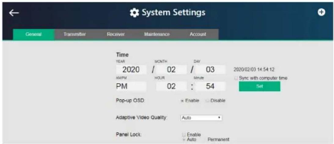
To access the General tab, click from the main screen, and then click the General tab.
- Date and time: Click and type the desired information and click Set to save the settings.
- Sync with computer time: If you wish to synchronize the time with the computer's time, check the checkbox and click Set.
- Pop-up OSD: When enabled, the OSD will be displayed when switching video source. The OSD will not be displayed when disabled.
- Video Quality: Click to select a video quality for display.
Panel Lock:
- Select Permanent to lock the panel control of all connected VE8900 / VE8950 devices. To unlock the panel of a single VE8900 / VE8950 device, uncheck the Enable checkbox.
- Select Auto to automatically lock the panel control of all connected VE8900 / VE8950 devices when it idles for 1 minutes. To unlock the panel of a single VE8900 / VE8950 device, press and hold the Down (-) button on the top panel for 3 seconds.
- Installation Wizard: Click ☐ on the top-right corner to open up the installation wizard. For details, see Logging In and Configuring VE Manager, page 25.
Click Apply for the settings to take effect on the connected VE8900 / VE8950 devices.
Transmitter Settings
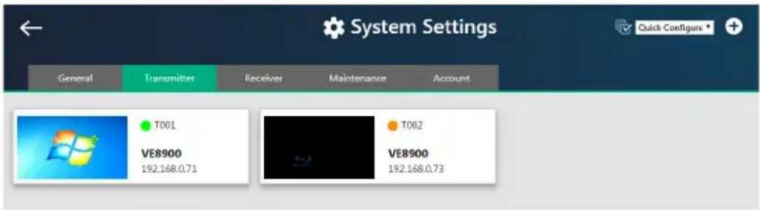
The Transmitter tab displays the managed VE8900 / VE8950 transmitter devices and provides access to the settings.
To access transmitter settings, follow the steps below.
- From the main screen, click 🔒, and then click the Transmitter tab. The managed VE8900 / VE8950 transmitters appear.
-
Move the cursor to a transmitter you wish to configure. A green arrow appears at the top right corner of the transmitter preview window.
-
Click the green arrow. A drop-down menu appears.
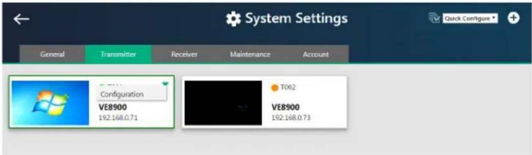
- Click Configuration. This window appears.
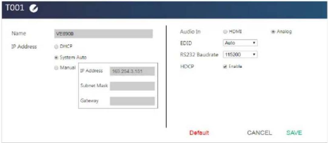
5. Configure the settings as required.
- Name: Click to rename the transmitter.
-
IP Address: Specifies how the transmitter obtains its IP address. By default, this field is set to System Auto.
-
DHCP: Select this option to have the IP address automatically assigned by a DHCP server.
- System Auto: Select this option to have the IP address automatically assigned by the VE Manager.
- Manual: Select this option to designate an IP address for the transmitter. Manually type the IP Address, Subnet Mask, and Gateway for the device.
◆ Audio In: Select your audio signal type.
- EDID: After receiving EDID information from the connected display, the VE8900T / VE8950T analyzes this information and sets up the input source. Select an EDID mode that suits your needs.
- Default: Sets up the input to an optimum configuration based on ATEN's predefined list of EDID.
- Auto: Sets up the input to the best resolution of the connected displays.
- Manual: Sets up the input to user’s configuration.
- Remix: Sets up the input to an optimum resolution of the connected displays.
◆ RS-232 Baud Rate: Select a suitable baud rate.
♦ HDCP: By default, HDCP is enabled for the VE8900T / VE8950T.
- Default: Click to restore the transmitter's settings to default.
- Click SAVE to keep the changes.
Receiver Settings
The Receiver tab displays managed VE8900 / VE8950 receiver devices and provides access to the settings.
To access receiver settings, follow the steps below.
- From the main screen, click 🔒, and then click the Receiver tab. The managed VE8900 / VE8950 receivers appear.
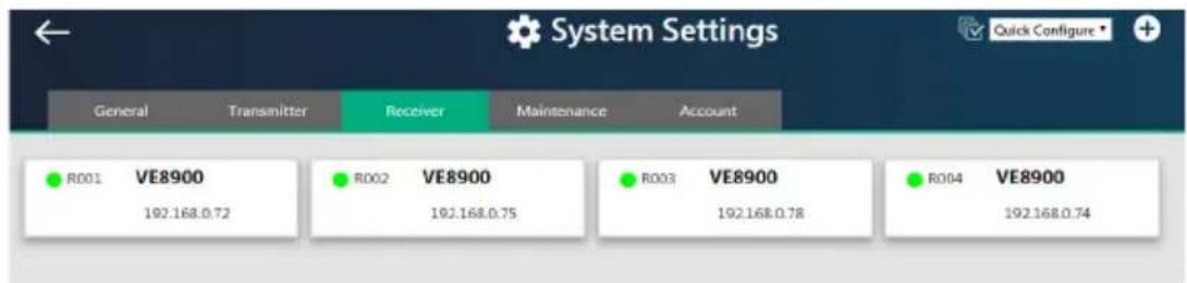
-
Move the cursor to a receiver you wish to configure. A green arrow appears at the top right corner of the receiver preview window.
-
Click the green arrow. A drop-down menu appears.
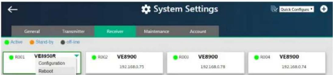
- From the drop-down menu, click Configuration. This window appears.
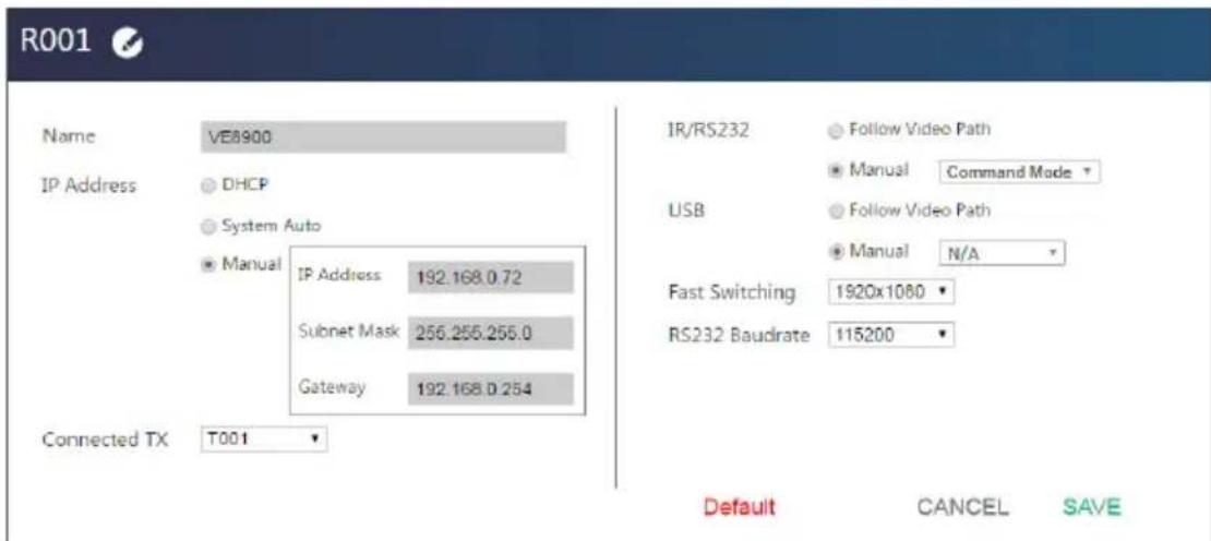
5. Configure the settings as required.
- Name: Type to name the receiver.
-
IP Address: Specifies how the receiver obtains its IP address. By default, this field is set to System Auto.
-
DHCP: Select this option to have the IP address automatically assigned by a DHCP server.
- System Auto: Select this option to have the IP address automatically assigned by the VE Manager.
-
Manual: Select this option to designate an IP address for the receiver. Manually type the IP Address, Subnet Mask, and Gateway for the device.
-
Connected Tx: Defines the video source for this receiver.
-
IR/RS-232: Sets the source for IR/RS-232 signals. By default, the IR and RS-232 are disabled (Manual > N/A).
-
Follow Video Path: Select this option to receive IR/RS-232 signals from the transmitter (Connected Tx) where the receiver obtains its video source.
- Manual: Use this setting to select a different source for obtaining IR/RS-232 signals.
- USB: Sets the source for the connected USB devices.
- Follow Video Path: Select this option to receive USB signals from the transmitter (Connected Tx) where the receiver obtains its video source.
- Manual: Use this setting to select a different source for obtaining USB signals.
- Fast Switching: Click to define the resolution for fast switching.
Note: For best results, ATEN recommends setting this field to the same resolution with your video source and make sure this setting is identical on all VE8900 / VE8950 receivers.
◆ RS-232 Baud Rate: Click to define the baud rate for the receiver.
- Default: Click to restore the receiver's settings in this window to default.
- Click SAVE to keep the changes.
Batch Configuration
A batch configuration option is available for both Transmitters and Receivers, and appears on the top right-hand corner of the page as Quick Configuration.
If you wish to adjust a particular setting for a group of devices, do the following:
- Click Quick Configuration for a drop-down menu.
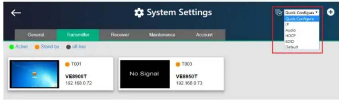
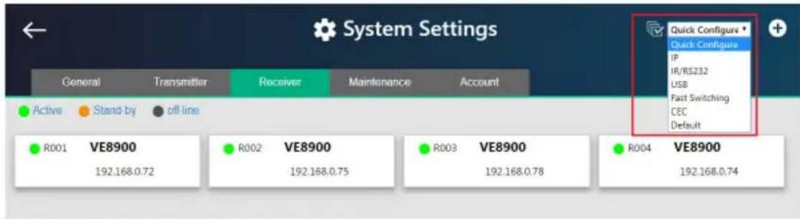
- Select a setting you wish to configure.
The available options for the drop-down menu will depend on whether you're in the Transmitter or Receiver settings.
- For Transmitters, please refer to page 50.
- For Receivers, please refer to page 52.
The interface will allow you to select which devices you wish to configure.
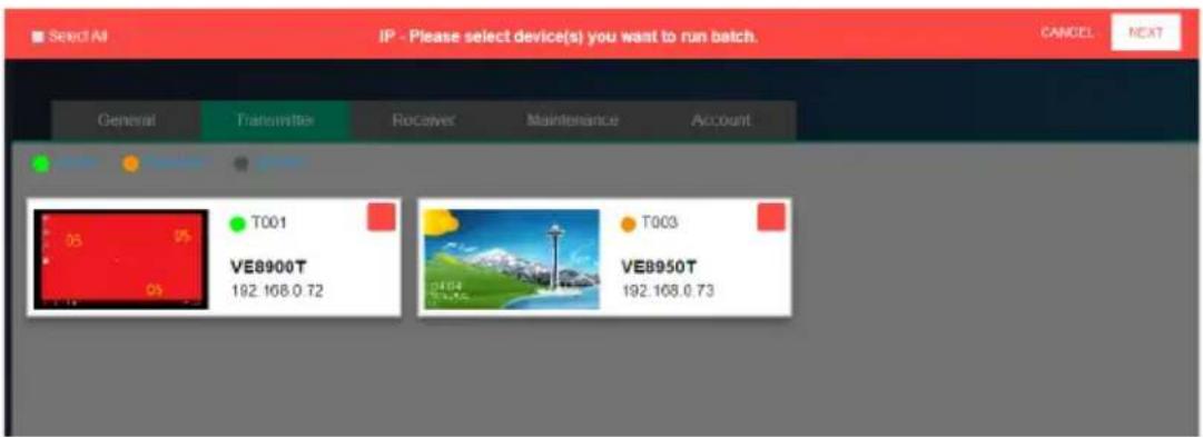
- Check the devices you wish to configure or, if you wish to select all the devices on the list, check "Select All" (on the top left-hand corner) and click NEXT.
The Quick Configure window will appear and you can see each device's current status.
A drop-down menu is available at the bottom of the window for the configuration.
| Quick Configure IP | |||
| ID | Name | Status | |
| T001 | VE8900T | Manual | |
| T003 | VE8950T | Manual | |
| Set All to DHCP | CANCEL | Apply | |
- Select the desired setting and click Apply to apply the setting to all the devices.
Maintenance
The Maintenance tab allows you to upgrade device firmware, back up transmitter and receiver layouts, and restore devices to previously backed up settings.
Upgrading VE8900 / VE8950 Device Firmware
To upgrade the VE8900 / VE8950 device firmware, follow the steps below.
- From the main screen, click 🔒, and click the Maintenance tab. This screen appears. The Firmware Upgrade section lists the detected transmitter and receiver devices, and their firmware versions.
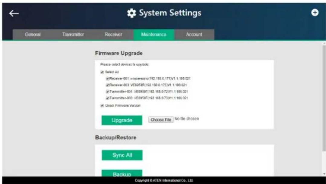
-
Click Choose File to locate a previously saved firmware file.
-
Click to uncheck any devices that do not require the upgrade.
-
By default, any upgrades that involve a version rollback will be ignored. To apply both upgrades and version rollbacks, uncheck Check Firmware Version.
-
Click Upgrade to start upgrading.
Synchronizing All Devices
When you wish to add or replace devices, click the Sync All button for the system to recognize the added / replaced device.
Backing Up VE8900 / VE8950 Device Settings
You can export transmitter and receiver layouts for backup or migration purposes.
- From the main screen, click 🔒, and then click the Maintenance tab. This screen appears.
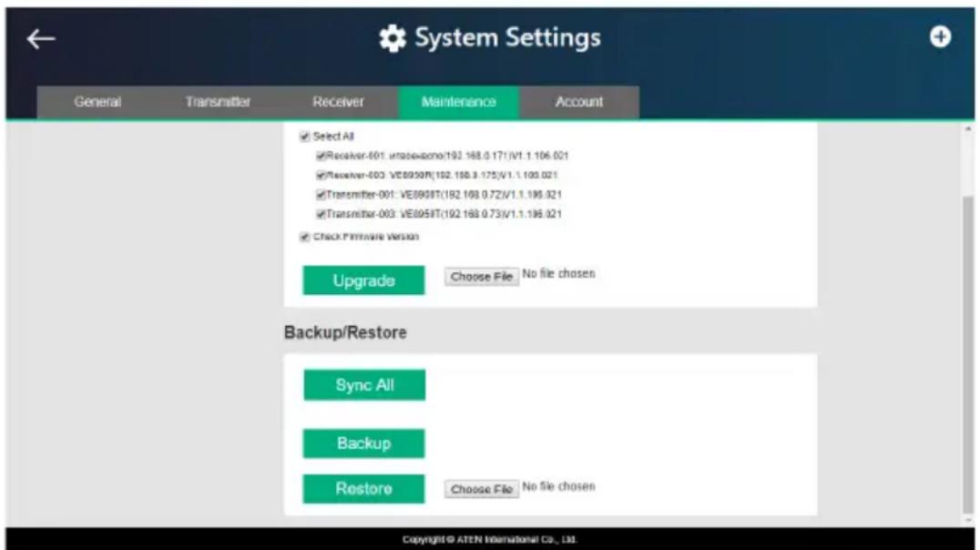
- Click Back up. A confirmation message appears when the backup is complete.
Restoring VE8900 / VE8950 Device Settings
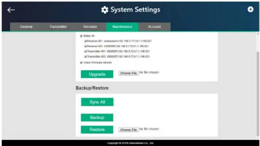
You can restore your VE Manager to a previously saved set of settings on transmitter and receiver layouts.
- From the main screen, click 🔒, and then click the Maintenance tab. This screen appears.
-
Click Choose File to locate a previously saved settings file.
-
Click Restore to start overwriting the settings to the VE Manager. A confirmation message appears when the backup is complete.
Account Settings
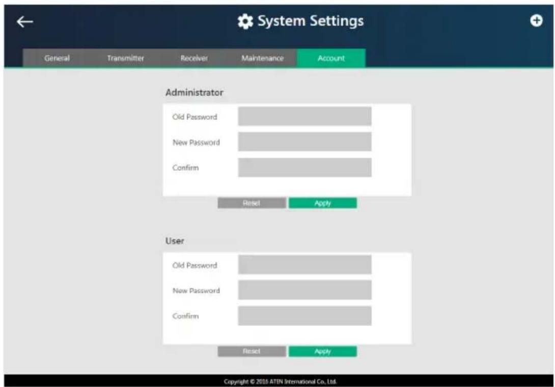
VE Manager contains two account levels, the Administrator and the User level. The default passwords and privileges are detailed in the table below.
| Account Level Default Password Privileges | |
| Administrator password All settings | |
| User password Source assignment and VE8900 / VE8950 receiver allocation on video wall layouts only | |
To change the default password, click from the main screen, and then click the Account tab.
Overview
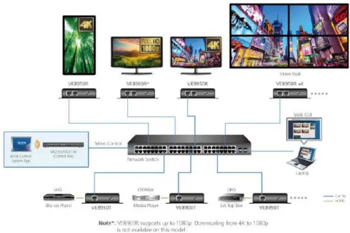
You can manage and configure the VE8900 / VE8950 devices using telnet, TCP, or RS-232 commands from a PC or an ATEN Control Box.
Before You Start
Make sure you have installed a PC or an ATEN Control Box to the network switch in your setup, as illustrated below:
flowchart
graph TD
    A["VE8950R"] --> B["Telvis Control"]
    C["VE8900R*"] --> B
    D["VE8950R"] --> B
    E["VE8950R x4"] --> B
    F["ATIN Control System App"] --> B
    G["VK200VX11 Do Control Box"] --> B
    H["Blu-ray Player"] --> I["VE8950T"]
    J["(1080p)"] --> K["Media Player"]
    L["(4K)"] --> M["Set-top Box"]
    N["Laptop"] --> O["Web GUI"]
    P["Video Wall"] --> Q["......"]
    R["4K"] --> S["VE8950T"]
    T["Note*: VE8900R supports up to 1080p. Downscaling from 4K to 1080p is not available on this model"]
Executing Commands
The following instructions presume command operations using a PC. To execute commands using ATEN Control Boxes, see ATEN Control System User Manual for details. To execute a command, do the following:
- On a connected PC, open a command prompt as administrator.
- Depending on the supported command type for your PC, do the following to connect to your deployment.
- Telnet connections
In the command prompt, type the IP address of any VE8900 / VE8950 receiver in your setup and use port 23. For example:
![Microsoft Windows [Version 6.1.7601] Copyright (c) 2009 Microsoft Corporation. All rights reserved. C:\Windows\system32\telnet 192.168.0.87 23_](/content/2026/05/1005482/images/7d10ac48aa2ed8f6cc083cc2280367313d1a6a694127406e44fbda61c4223da8.jpg)
- TCP connections
In the command prompt, type the IP address of any VE8900 / VE8950 receiver in your setup and use port 9138. For example:
![C:\Windows\System32\cmd.exe Microsoft Windows [Version 6.1.7601] Copyright (c) 2009 Microsoft Corporation. All rights reserved. C:\Windows\system32\tcp 192.168.0.87 9138.](/content/2026/05/1005482/images/5778c96d6d32afc13a49138e1e102a281bc0d3257a879faf621e3627e20b9d22.jpg)
RS-232 connections
In the VE Manager, set the IR/RS232 of all VE8900 / VE8950 receivers to Manual and select the Command Mode option.
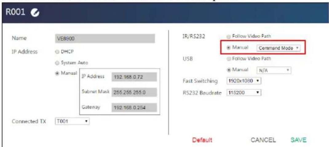
When the connection is established, the message “Welcome to CLI mode” appears.
- Type the command you wish to execute.
For information on command syntax, see Commands, page 62.
-
Press [Enter] to execute the command.
-
When the command is successfully executed, the system returns a confirmation message.
-
To end the session, type logout in the command prompt and press [Enter].
Commands
Guidelines
- The general form of a command is: command name + parameter1 + parameter 2 + control 1 + control 2
- Always specify the command name first, followed by one or more parameters, and then the controls, if any.
If you have two or more parameters, the order of these parameters among themselves does not affect the result of the operation. For example, both of the following commands execute the same task:
command name + parameter 1 + parameter 2
command name + parameter 2 + parameter 1
If you have two or more controls, the order of these controls among themselves does not affect the result of the operation. For example, both of the following commands execute the same task:
command name + control 1 + control 2
command name + control 2 + control 1
- The command syntax uses the following notifications:
| Notation | Description |
| + Indicates a space in the command. | |
| [ ] Indicates optional items. Only type the information in the brackets, not the brackets themselves. | |
| Indicates the name of the value that the user must provide. Only type the information in the angle brackets, not the brackets themselves. | |
| | Indicates two or more mutually exclusive choices in a command line. Only type one of the choices in the command line, not the symbol. | |
Switching Sources
To switch source on a display, type the command in this format:
$$ \mathrm{sw} + \mathrm{i} < \text {port} > + [ \mathbf {o} < \text {port} > ] + \text {on} | \text {off} + \backslash \mathrm{r} \backslash \mathrm{n} $$
| Control Description | |
| iIndicates the device ID, MAC address, or the IP address of the input source (VE8900 / VE8950 transmitter) device. | |
| oIndicates the device ID, MAC address, or the IP address of the output (VE8900 / VE8950 receiver) device. Omit this variable to assign the specified source to the display that you used to make the CLI connection. | |
| on Enables the | specified command. |
| off Disconnects | from the current connection. |
| \r\n Ends the command. | |
Examples
- To switch the source to a VE8900 transmitter with the IP address of 10.0.90.11 to the VE8900 receiver you used to make the CLI connection, type sw i10.0.90.11 on
- To switch the source to a VE8950 transmitter with the ID of 1 on a VE8950 receiver with the ID of 5, type sw i1 o5 on
- To stop source transmission from a VE8900 transmitter with the IP address of 10.0.70.43 to a VE8900 receiver with the ID of 3, type sw i10.0.70.43 o3 off
Switching Video, USB, RS-232, and/or IR Paths
Use this command to switch video, USB, RS-232 and/or IR transmission paths. To use this function, type the command in this format:
sw + i
| Control Description | |
| iIndicates the device ID of the input source (VE8900 / VE8950 transmitter) device. | |
| oIndicates the device ID of the output (VE8900 / VE8950 receiver) device. | |
| all Stands for all transmissions paths, including video, USB, and IR of the specified transmitter. | |
| video Stands for video path of the specified transmitter. | |
| usb Stands for USB path of the specified transmitter. | |
| serial Stands for RS-232 path of the specified transmitter. | |
| ir Stands for IR path of the specified transmitter. | |
| \r\n Ends the command. |
Examples
To switch the video path of a VE8900 transmitter with the ID of 3 to a VE8900 receiver with an ID of 4, type sw i3 video o4
- To switch the usb path of a VE8950 transmitter with the ID of 1 to a VE8950 receiver with an ID of 6, type sw i1 usb o6
Disabling Video, USB, RS-232, and/or IR Paths
Use this command to disable video, USB, RS-232 and/or IR transmission paths for the specified VE8900 / VE8950 receiver. To use this function, type the command in this format:
$$ \mathrm{sw} + \mathrm{o} < \text {port} > + \text {all} | \text {video} | \text {usb} | \text {serial} | \text {ir} + \text {off} + \backslash R \backslash N $$
| Control Description | |
| oIndicates the device ID of the output (VE8900 / VE8950 receiver) device. | |
| all Stands for all transmissions paths, including video, USB, and IR of the specified receiver. | |
| video Stands for video path of the specified receiver. | |
| usb Stands for USB path of the specified receiver. | |
| serial Stands for RS-232 path of the specified receiver. | |
| ir Stands for IR path of the specified receiver. | |
| \r\n Ends the command. |
Example
- To disable the video, USB, RS-232, and IR paths for a VE8900 receiver with an ID of 4, type sw o4 all off
Displaying Port-Switching Alerts
Use this command to display an alert message in the command line interface whenever a port is switched via the VE Manager, the VE8900 / VE8950 device pushbuttons, or the IR remote control. To enable or disable this function, type the command in this format:
$$ \text { echo } + \text { on } | \text { off } + \backslash R \backslash N $$
| Control Description | |
| on Sends an alert in the command prompt window to inform port switching configuration. For example, when the user assigns the VE8900T with the device ID of 2 to the VE8900R with the device ID of 3, the system send this message in the command prompt window:sw o2 i3 on | |
| off Disables the alert for port switching. | |
| \r\n Ends the command. |
Looking Up System Settings
You can look up the following system settings using the list command:
◆ Video Wall IDs
◆ Device ID, MAC address, IP address, firmware version, and device name of VE8900 / VE8950 transmitters and receivers
To look up system settings, type the command in this format:
list + rx | tx | device | videowall + \r\n
| Control Description | |
| rx Lists the system information of all VE8900 / VE8950 receivers in the environment, including the device IDs, MAC addresses, IP addresses, firmware versions, and device names. | |
| tx Lists the system information of all VE8900 / VE8950 transmitters in the environment, including the device IDs, MAC addresses, IP addresses, firmware versions, and device names. | |
| device Lists the system information of all VE8900 / VE8950 transmitters and receivers in the environment, including the device IDs, MAC addresses, IP addresses, firmware versions, and device names. | |
| videowall Lists the video wall settings. | |
| \r\n Ends the command. |
Configuring Video Wall Settings
To apply a layout to a video wall and assign sources for display, type the command in this format:
vw + f
| Control Description | |
| Indicates the ID of the video wall on which you wish to display the specified layout and sources. You can also substitute this ID with the ID of any VE8900 / VE8950 receiver used in the target video wall. To look up video wall IDs, use the list command. For details, see Looking Up System Settings, page 67. | |
| I | Indicates the name of the layout that you wish to apply to the specified video wall. To look up layout IDs, use the list command. For details, see Looking Up System Settings, page 67. Omit this element when you want to use the same layout that is applied to the target video wall. |
| i | Indicates the device ID, MAC address, or the IP address of the input (VE8900 / VE8950 transmitter) device you wish to use. |
| o | Indicates the device ID, MAC address, or the IP address of the output (VE8900 / VE8950 receiver) device on which you wish display the specified source (i).Note: If the specified layout contains a 4 displays, two of which are merged, you will need 3 pairs of o+i to indicate the source to be displayed on each display. Omit the o-element when specified layout does not contained any merged screens. |
| \r\n Ends the command. | |
Examples
To apply Layout 1 to a video wall with the ID of 8c8f12e62d3c87ef, and assign the source connected to VE8950T (device ID: 2) to the video wall, where one of the display is connected to a VE8900R (IP address:
10.0.66.73), type the following:
vw + f8c8f12e62d3c87ef + lLayout 1 + o10.0.66.73 + i2 + on
Muting VE8900 / VE8950 Receivers or Video Walls
To mute audio output on a VE8900R / VE8950R or a video wall, type the command in this format:
$$ \text { mute } + \text { o < port } > | f < \text { video_wall_ID } > + \text { on } | \text { off } + / r / n $$
| Control Description | |
| oIndicates the device ID, MAC address, or the IP address of the output (VE8900 / VE8950 receiver) device you wish to mute. Use an asterisk (*) to mute all VE8900 / VE8950 receivers in the setup. | |
| on Mutes the specified VE8900 / VE8950 receivers or video walls. | |
| off Unmutes the specified VE8900 / VE8950 receivers or video walls. | |
| \r\n Ends the command. | |
Examples
- To mute a VE8900 receiver with the IP address 10.0.90.22, type mute o10.0.90.22 on
◆ To mute a video wall with the Video Wall ID 0, type mute f0 on
◆ To unmute a video wall with the Video Wall ID 1, type mute f1 off
Disabling a Video Output
To disable video output from a specific receiver or on a particular video wall, type the command in this format:
blankscreen + o
| Control Description | |
| oIndicates the device ID, MAC address, or the IP address of the output (VE8900 / VE8950 receiver) device you wish to disable the video output from, or use * to disable video output from all VE8900 / VE8950 receivers in the setup. | |
| on Stops video output from the specified VE8900 / VE8950 receivers or on the specified video wall. | |
| off Allows video output from the specified VE8900 / VE8950 receivers or on the specified video walls. | |
| \r\n Ends the command. | |
Examples
- To disable video output on the VE8900 receiver with the IP address of 10.0.90.22, type blankscreen o10.0.90.22 on
- To enable video output on the video wall with the Video Wall ID 0, type blankscreen f0 off
Enabling/Disabling the OSD Display of a Receiver
To enable or disable the OSD display of a specified receiver, type the command in this format:
osd + o
| Control Description | |
| oIndicates the device ID, MAC address, or the IP address of the output (VE8900 / VE8950 receiver) device for which you wish to display the OSD. | |
| on Displays the OSD of the specified VE8900 / VE8950 receiver. | |
| off Hides the OSDs of the specified VE8900 / VE8950 receivers. | |
| \r\n Ends the command. | |
Examples
- To display the OSD of a VE8900 receiver with the IP address 10.0.90.22, type osd o10.0.90.22 on
- To hide the OSDs of the VE8900 / VE8950 receivers for a video wall with the Video Wall ID 0, type osd f0 off
Configuring the EDID Mode
To set the EDID mode of a specified VE8900 / VE8950 transmitter, type the command in this format:
$$ \text { edid } + \mathrm{i} < \text { port } > + < \text { EDID_mode } > + \mathrm {\backslash r\n} $$
| Control Description | |
| iIndicates the device ID, MAC address, or the IP address of the output (VE8900 / VE8950 transmitter) device connected to the source of the target display. | |
| Indicates the EDID mode you wish to set to the specified VE8900 / VE8950 transmitter. Valid inputs includedefault, remix, auto, and manual.Default: Sets up the input to an optimum configuration based on EDID predefined by ATEN.Auto: Sets up the input to the highest resolution of the connected displays.Manual: Sets up the input to user's configuration.Remix: Sets up the input to an optimum resolution of the connected displays. | |
| \r\n Ends the command. |
Examples
- To set the EDID mode of a VE8900 transmitter with the device ID of 16 to auto, type edid i016 auto
Reseting the VE8900 / VE8950 Devices
To set VE8900 / VE8950 devices to default, type the command in this format:
reset + a
| Control Description | |
| aIndicates the MAC address or the IP address of the target VE8900 / VE8950 transmitter or receiver. Use an asterisk (*) to target all VE8900 / VE8950 transmitters and receivers in the environment. | |
| iIndicates the device ID of the target input source (VE8900 / VE8950 transmitter) device. Use an asterisk (*) to target all VE8900 / VE8950 transmitters in the environment. | |
| oIndicates the device ID of the target output (VE8900 / VE8950 receiver) device. Use an asterisk (*) to target all VE8900 / VE8950 receivers in the environment. | |
| \r\n Ends the command. |
Examples
- To set the VE8900 transmitter with the IP address of 10.0.60.13 to default, type reset i10.0.60.13 or reset a10.0.60.13
To set allVE8900 / VE8950 receivers to default, type reset o*
Setting the Baud Rate
To set the baud rate of RS-232 serial transmission for VE8900 / VE8950 devices, type the command in this format:
baud + a
| Control Description | |
| aIndicates the MAC address or the IP address of the target VE8900 / VE8950 transmitter or receiver. Use an asterisk (*) to target all VE8900 / VE8950 transmitters and receivers in the environment. | |
| iIndicates the device ID of the target input source (VE8900 / VE8950 transmitter) device. Use an asterisk (*) to target all VE8900 / VE8950 transmitters in the environment. | |
| oIndicates the device ID of the target output (VE8900 / VE8950 receiver) device. Use an asterisk (*) to target all VE8900 / VE8950 receivers in the environment. | |
| \r\n Ends the command. | |
Examples
- To set the baud rate of a VE8900 transmitter with the device ID of 3 to 115200, type baud a3 115200
◆ To set all VE8900 / VE8950 receivers to default, type baud o* 9600
Displaying Device Status
You can display the status of VE8900 / VE8950 transmitters or receivers, or the connection status of VE8900 / VE8950 transmitters to VE8900 / VE8950 receivers. To do this, type the command in this format:
$$ \text { read } + [ i < \text { port } > ] \mid [ o < \text { port } > ] + \backslash r \backslash n $$
| Control Description | |
| iIndicates the device ID, MAC address, or the IP address of the target input source (VE8900 / VE8950 transmitter) device. Use an asterisk (*) to target all VE8900 / VE8950 transmitters in the environment. | |
| oIndicates the device ID, MAC address, or the IP address of the target output (VE8900 / VE8950 receiver) device. Use an asterisk (*) to target all VE8900 / VE8950 receivers in the environment. | |
| \r\n Ends the command. |
Examples
- To look up the device status of all VE8900 / VE8950 transmitters, type read i*
- To look up the device status of a VE8900 / VE8950 receiver with the IP address of 10.0.80.66, type read o10.0.80.66
- To look up the connection status of VE8900 / VE8950 transmitters to VE8900 / VE8950 receivers in the environment, type read
This Page Intentionally Left Blank
Overview
The VE8900 / VE8950 Mobile Control App is designed to help you conveniently switch sources/displays and apply and reschedule profiles for your VE8900 / VE8950 devices.
Requirements
Make sure your mobile device uses a supported version of the mobile operating system listed below before installing the app.
| Mobile Operating System Supported Version | |
| iOS 10.0 or later | |
| Android 6.0 or later | |
Installing and Configuring the App
- Install the VE8900 / VE8950 Mobile Control App on a mobile device.
a) From the mobile device, tap the App Store icon.
or Google Play
b) In the search box, type "VE8900 mobile control".
c) Tap VE8900 Mobile Control and install the app.


-
From the mobile device, tap the VE8900 Mobile Control App icon.
-
Follow the on-screen instructions to:
-
enable the mobile device's WiFi service.
- connect the mobile device to the network where the video extenders are installed.
Main Page
When logged in, the VE8900 / VE8950 Mobile Control App defaults to the live view page. Use the icons at the bottom of the screen to access different sets of functions. Refer to the table below for an overview of the functions on each tab.
Note: If you are the administrator, and are logging in for the first time, use the default Password: password. For security purposes, the system will prompt you to change the login password. The password must be different from your login password
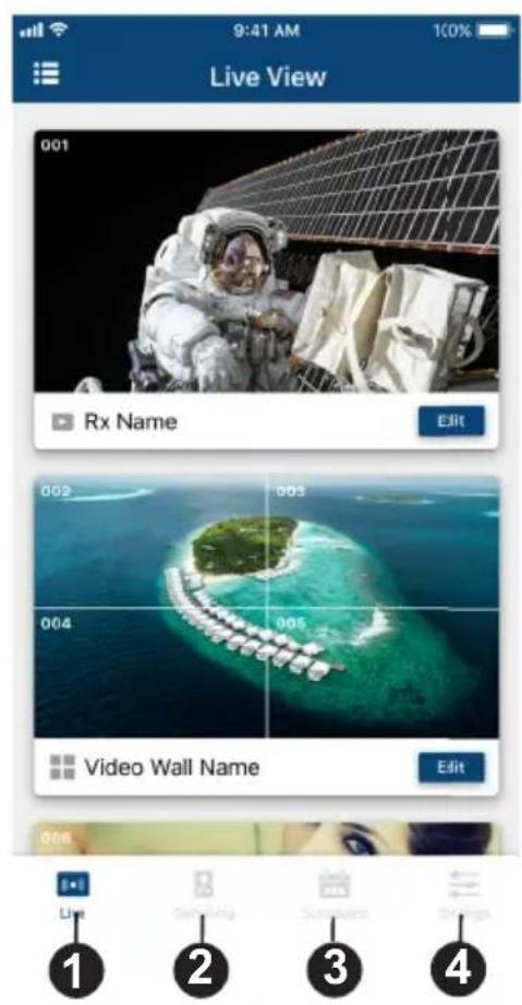
| No. | Component Description |
1 Tap  | icon to show live views of established video walls and receivers. |
| 2 Tap [Switching] | icon to change display sources and target receivers. |
| 3 Tap this icon to configure the schedules of existing profiles.Schedules. For details on creating a new profile, see Profile, page 38. | |
| 4 Tap this icon to configure system settings or upgrade transmitter/receiver firmware. | |
Live Views
To see live views for your displays, follow the steps below.
-
In the VE8950 Mobile Control App, tap the Live Live icon. A list of video walls and/or displays appear, along with their selected sources.
-
Scroll up and down to view the list. If you have installed new display devices or made changes to the settings, tap Sync 🔍 t o
Switching a Source
-
In the VE8950 Mobile Control App, tap the Live i c o n .
-
Tap any area on the receiver or the video wall for which you wish to change the source.
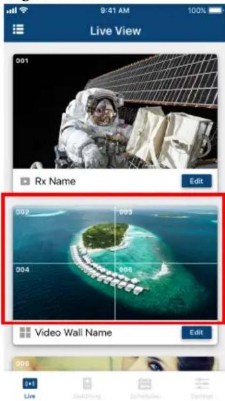
- Tap the source you wish to change to. Currently used source is indicated with a red box, and the new source is in green.
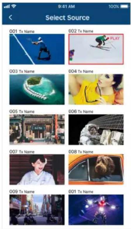
- Tap the tick icon on the selected source to apply the configuration.
Switching Multiple Sources and Displays
- In the VE8950 Mobile Control App, tap the Switching Switching icon. This screen appears.
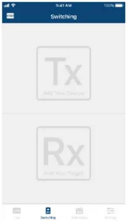
- Select a source.
a) Tap Tx to add a source. A list of available transmitters appear.
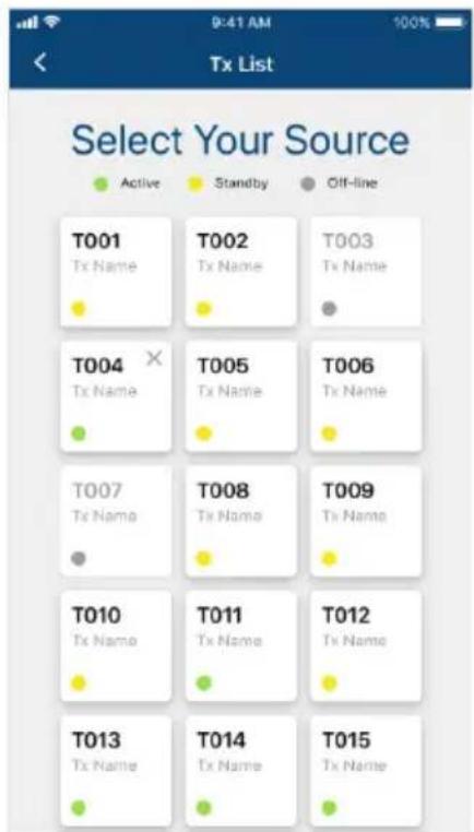
b) Tap to select a transmitter. The selected device is indicated in green. Tap again to cancel the selection.
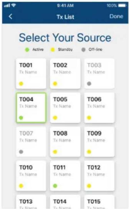
c) Tap Done to add the device to the Tx List.
-
Select one or more displays. Tap Rx to add one or more Rx devices.
-
Selected Rx devices are indicated in green.
- When you tap a device that is grouped with other Rx devices (for video wall or splitter applications), all the devices of the group will be indicated in green at the same time.
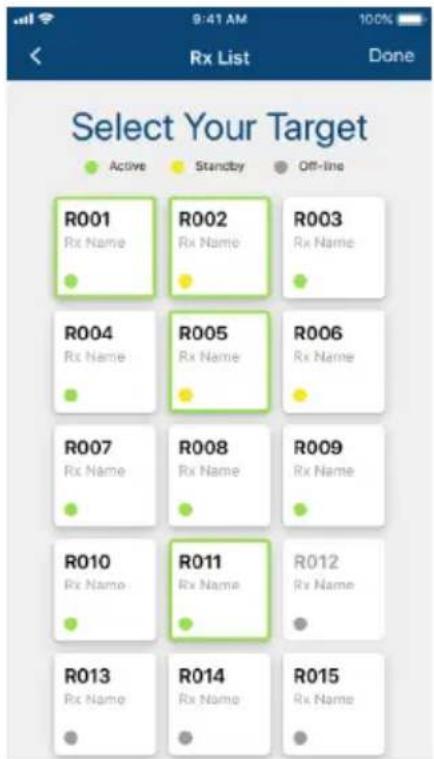
When you have finished configuring, the Tx and Rx lists should contain the devices you selected. For example:
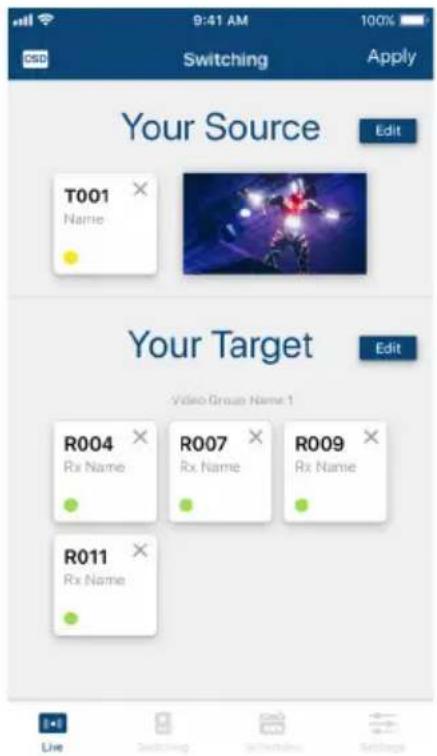
-
To edit your selection, tap to return to the Tx or Rx list.
-
Tap Apply to complete the configuration. The changes take effect immediately.
Changing the Operation Mode of a Video Wall/Display
-
In the VE8950 Mobile Control App, tap the Live icon.
-
Find the video wall or the display that you wish to configure, and then tap the Edit icon. This page appears.
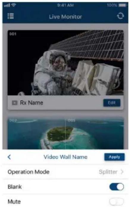
- Tap Operation Mode to change the display setting.
For details on different operation modes, see Creating a Video Wall Layout, page 34.
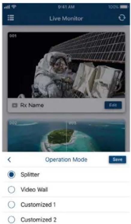
Applying a Display Profile
If you already have display profiles configured using VE Manager, follow the steps below to apply a profile. For details on creating or editing a profile, see Creating a Profile, page 38 and Edit, Delete and Disconnect Profile, page 40.
- In the VE8950 Mobile Control App, tap the Live icon.
- Tap on the top-left of the screen. A list of profiles appears.
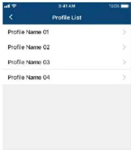
- Tap any of the profile and follow the on-screen instructions to apply the profile.
Configuring the Profile Schedule
- In the VE8950 Mobile Control App, tap the Schedules icon. The schedules for the day appear.
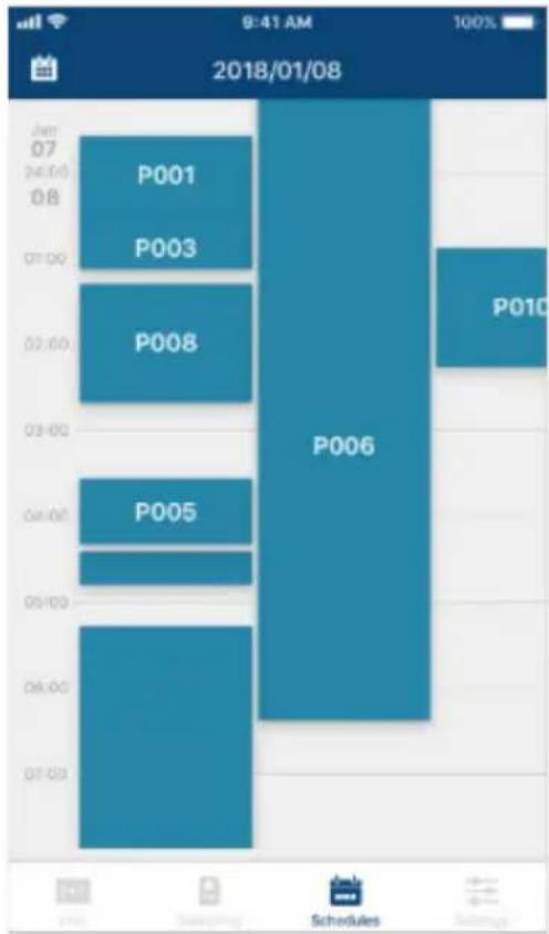
bar
| Time | P001 (%) | P003 (%) | P006 (%) | P010 (%) | |---|---|---|---|---| | 07:00 | | | | | | 08:00 | | | | | | 09:00 | | | | | | 10:00 | | | | | | 11:00 | | | | | | 12:00 | | | | | | 13:00 | | | | | | 14:00 | | | | | | 15:00 | | | | | | 16:00 | | | | | | 17:00 | | | | | | 18:00 | | | | | | 19:00 | | | | | | 20:00 | | | | | | 21:00 | | | | | | 22:00 | | | | | | 23:00 | | | | | | 24:00 | | | | | | 25:00 | | | | | | 26:00 | | | | | | 27:00 | | | | | | 28:00 | | | | | | 29:00 | | | | | | 30:00 | | | | | | 31:00 | | | | | | 32:00 | | | | | | 33:00 | | | | | | 34:00 | | | | | | 35:00 | | | | | | 36:00 | | | | | | 37:00 | | | | | | 38:00 | | | | | | 39:00 | | | | | | 40:00 | | | - | - | | Note: The values in the 'P' column are estimated based on the 'P' label in the chart, so they are not explicitly provided in the code. The 'Schedules' and 'Settings' labels are not present in the chart.- To change the display date, tap off the top-left corner and select a date from the pop-up calendar.
- Tap on the time zone that contains the profile you want to configure. All the profiles that run into or over the selected time zone are listed. For example, tap any where between 04:00 to 05:00. Four profiles can be configured.
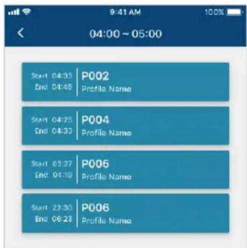
- Tap a profile and follow the on-screen instructions to configure its Start Date, End Date, and Repeat mode.
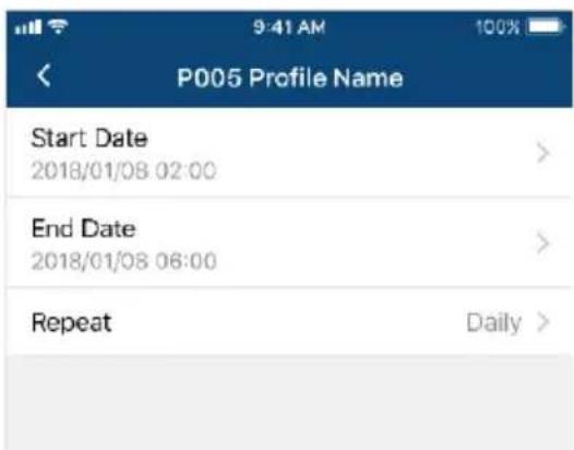
Note: Keep the Start Date and End Date within 24 hours. If you need to schedule a profile for more than 24 hours per repeat unit, use two profiles to resolve the issue.
System Settings and Status
You can use the Mobile Control App to find out if a newer firmware is available for the VE8900/VE8950 devices and configure the Video Quality and Pop-up OSD setting.
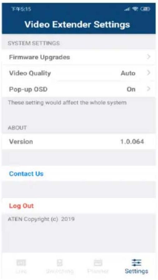
- Firmware Upgrades: Shows the firmware versions for the VE8900/VE8950 Tx and Rx devices and indicate if a newer firmware is available for each Tx/Rx device.
♦ Video Quality: Sets the video quality for displays. - Pop-up OSD: When enabled, the OSD will be displayed when switching video source. The OSD will not be displayed when disabled.
General
- This product is for indoor use only.
- Read all of these instructions. Save them for future reference.
- Follow all warnings and instructions marked on the device.
- Do not place the device on any unstable surface (cart, stand, table, etc.). If the device falls, serious damage will result.
- Do not use the device near water.
- Do not place the device near, or over, radiators or heat registers.
- The device cabinet is provided with slots and openings to allow for adequate ventilation. To ensure reliable operation, and to protect against overheating, these openings must never be blocked or covered.
- The device should never be placed on a soft surface (bed, sofa, rug, etc.) as this will block its ventilation openings. Likewise, the device should not be placed in a built-in enclosure unless adequate ventilation has been provided.
- Never spill liquid of any kind on the device.
- Unplug the device from the wall outlet before cleaning. Do not use liquid or aerosol cleaners. Use a damp cloth for cleaning.
- The device should be operated from the type of power source indicated on the marking label. If you are not sure of the type of power available, consult your dealer or local power company.
- The device is designed for IT power distribution systems with 230V phase-to-phase voltage.
- To prevent damage to your installation it is important that all devices are properly grounded.
- The device is equipped with a 3-wire grounding type plug. This is a safety feature. If you are unable to insert the plug into the outlet, contact your electrician to replace your obsolete outlet. Do not attempt to defeat the purpose of the grounding-type plug. Always follow your local/national wiring codes.
- Do not allow anything to rest on the power cord or cables. Route the power cord and cables so that they cannot be stepped on or tripped over.
If an extension cord is used with this device make sure that the total of the ampere ratings of all products used on this cord does not exceed the extension cord ampere rating. Make sure that the total of all products plugged into the wall outlet does not exceed 15 amperes.
- To help protect your system from sudden, transient increases and decreases in electrical power, use a surge suppressor, line conditioner, or uninterruptible power supply (UPS).
- Position system cables and power cables carefully; Be sure that nothing rests on any cables.
- Never push objects of any kind into or through cabinet slots. They may touch dangerous voltage points or short out parts resulting in a risk of fire or electrical shock.
- Do not attempt to service the device yourself. Refer all servicing to qualified service personnel.
- If the following conditions occur, unplug the device from the wall outlet and bring it to qualified service personnel for repair.
- The power cord or plug has become damaged or frayed.
♦ Liquid has been spilled into the device. - The device has been exposed to rain or water.
- The device has been dropped, or the cabinet has been damaged.
- The device exhibits a distinct change in performance, indicating a need for service.
- The device does not operate normally when the operating instructions are followed.
- Only adjust those controls that are covered in the operating instructions. Improper adjustment of other controls may result in damage that will require extensive work by a qualified technician to repair.
Rack Mounting
- Before working on the rack, make sure that the stabilizers are secured to the rack, extended to the floor, and that the full weight of the rack rests on the floor. Install front and side stabilizers on a single rack or front stabilizers for joined multiple racks before working on the rack.
- Always load the rack from the bottom up, and load the heaviest item in the rack first.
- Make sure that the rack is level and stable before extending a device from the rack.
- Use caution when pressing the device rail release latches and sliding a device into or out of a rack; the slide rails can pinch your fingers.
- After a device is inserted into the rack, carefully extend the rail into a locking position, and then slide the device into the rack.
- Do not overload the AC supply branch circuit that provides power to the rack. The total rack load should not exceed 80 percent of the branch circuit rating.
- Make sure that all equipment used on the rack – including power strips and other electrical connectors – is properly grounded.
- Ensure that proper airflow is provided to devices in the rack.
- Ensure that the operating ambient temperature of the rack environment does not exceed the maximum ambient temperature specified for the equipment by the manufacturer.
- Do not step on or stand on any device when servicing other devices in a rack.
Technical Support
International
- For online technical support – including troubleshooting, documentation, and software updates: http://support.aten.com
- For telephone support, see Telephone Support, page v:
North America
| Email Support support@aten-usa.com | ||
| Online Technical Support | Troubleshooting Documentation Software Updates | http://www.aten-usa.com/support |
| Telephone Support 1-888-999-ATEN | ext 4988 | |
When you contact us, please have the following information ready beforehand:
Product model number, serial number, and date of purchase
- Your computer configuration, including operating system, revision level, expansion cards, and software
◆ Any error messages displayed at the time the error occurred
◆ The sequence of operations that led up to the error
◆ Any other information you feel may be of help
Specifications
| Function VE8900R VE8950R VE8900T VE8950T | |||||
| Video Input | |||||
| Interfaces N/A 1 x HDMI Type A Female (Black) | |||||
| Impedance N/A 100 Ω | |||||
| Max. Distance N/A 1.8 m | |||||
| Video Output | |||||
| Interfaces 1 x HDMI Type A Female (Black) N/A | |||||
| Impedance 100 Ω N/A | |||||
| Video | |||||
| Max. Data Rate Average: 150 ~ 500Mbps Average: 150 ~ 500Mbps | |||||
| Compliance | HDMI HDCP Compatible | HDMI (4K) HDCP Compatible | HDMI HDCP Compatible | HDMI (4K) HDCP Compatible | |
| Max. Resolutions / Distances | Up to 1080p@100m (Cat 5e/6, point to point) | Up to 4K@100m (Cat 5e/6, point to point)*4K supported: 4096 x 2160 / 3840 x 2160 @ 30Hz (4:4:4) | Up to 1080p@100m (Cat 5e/6, point to point) | Up to 4K@100m (Cat 5e/6, point to point)*4K supported: 4096 x 2160 / 3840 x 2160 @ 60Hz (4:2:0) 4096 x 2160 / 3840 x 2160 @ 30Hz (4:4:4) | |
| Audio | |||||
| Input | N/A | 1 x HDMI Type A Female (Black)1 x Mini Stereo Jack Female (Green) | |||
| Output | 1 x HDMI Type A Female (Black)1 x Mini Stereo Jack Female (Green) | N/A | |||
| Connectors | |||||
| Unit to Unit | 2 x RJ-45 Female | 1 x RJ-45 Female | |||
| Control | |||||
| IR | 1 x Mini Stereo Jack Female (Black) | 1 x Mini Stereo Jack Female (Black) | |||
| RS-232 | Connector | 1 x Terminal Block, 3 x Pole | 1 x Terminal Block, 3 x Pole | ||
| Baud Rate | 19200 | 19200 | |||
| Data Bits | 8 | 8 | |||
| Stop Bits | 1, no parity and flow control | 1, no parity and flow control | |||
| USB | 2 x USB Type A Female (Black) | 1 x USB Type B Female (White) | |||
| Power | |||||
| Connectors | 1 x DC Jack (Black) with locking | 1 x DC Jack (Black) with locking | |||
| Power Consumption | DC5V: 4.28W(without USB peripheral device loading) | DC5V: 4.53W(without USB peripheral device loading) | DC5V: 3.07W | DC5V: 3.08W | |
| Function VE8900R VE8950R | VE8900T VE8950T | |||
| Environmental | ||||
| Operating Temperature | 0 - 40°C | 0 - 40°C | ||
| Storage Temperature | -20 | -60°C | -20 - 60°C | |
| Humidity 0 x 80% RH, Non-Condensing 0 x 80% RH, Non-Condensing | ||||
| Physical Properties | ||||
| Housing Metal Metal | ||||
| Weight 0.49 Kg (1.08 lb) | 0.50 Kg (1.10 lb) | |||
| Dimensions (L x W x H) with Bracket | 14.02 x 12.30 x 3.06 cm(5.52 x 4.84 x 1.20 in.) | 14.02 x 12.30 x 3.06 cm(5.52 x 4.84 x 1.20 in.) | ||
| Dimensions (L x W x H) without Bracket | 13.60 x 10.10 x 2.96 cm(5.35 x 3.98 x 1.17 in.) | 13.60 x 10.10 x 2.90 cm(5.35 x 3.98 x 1.14 in.) | ||
Note: Supports 1920x1200@60Hz reduced blanking (ATEN Default EDID only).
Supported Browsers
Please see the table below for supported web browsers and the versions.
| Web Browser Supported Versions | |
| Google Chrome 60.0.3112 or later | |
| Mozilla Firefox 54.0.1 or later | |
| Opera 46 or later |
Limited Warranty
ATEN warrants its hardware in the country of purchase against flaws in materials and workmanship for a Warranty Period of two [2] years (warranty period may vary in certain regions/countries) commencing on the date of original purchase. This warranty period includes the LCD panel of ATEN LCD KVM switches. Select products are warranted for an additional year (see A+ Warranty for further details). Cables and accessories are not covered by the Standard Warranty.
What is covered by the Limited Hardware Warranty
ATEN will provide a repair service, without charge, during the Warranty Period. If a product is detective, ATEN will, at its discretion, have the option to (1) repair said product with new or repaired components, or (2) replace the entire product with an identical product or with a similar product which fulfills the same function as the defective product. Replaced products assume the warranty of the original product for the remaining period or a period of 90 days, whichever is longer. When the products or components are replaced, the replacing articles shall become customer property and the replaced articles shall become the property of ATEN.
To learn more about our warranty policies, please visit our website: http://www.aten.com/global/en/legal/policies/warranty-policy/

- EMC Information
- RoHS
- About This Manual
- Conventions
- Product Information
- User Information
- Online Registration
- Telephone Support
- User Notice
- Package Contents
- VE8900T
- VE8900R
- VE8950T
- VE8950R
- Contents
- Introduction and Getting Started
- Hardware Setup
- Panel Operation
- Management
- System Settings
- CLI Commands
- Mobile Control App
- Appendix
- Introduction and Getting Started
- Overview
- Features and Benefits
- Light weight Compression with Ultra-low Latency
- Limitless Scalability and Flexibility
- Collaboration with ATEN Control System
- Spontaneous Scheduling Management
- No Complicated IP Setup
- Web GUI-Based Management, No Additional Server PCs or Software Required
- Go Further For Less with Daisy Chaining
- Video Wall Support
- Embedded / De-embedded Audio Support
- Multiple Control Channels
- Getting Started Tasks
- Chapter 2
- Hardware Setup
- Components
- VE8900T / VE8950T Front View
- VE8900T / VE8950T Rear View
- VE8900R / VE8950R Front View
- VE8900R / VE8950R Rear View
- Mounting the VE8900 / VE8950 Device
- Wall Mount
- Rack Mount
- Connecting VE8900 / VE8950
- Note:
- Chapter 3
- Panel Operation
- Status LEDs
- Panel Controls
- Assigning Sources Using the Device Panel
- Chapter 4
- Management
- Looking Up the Login IP Address
- Find My VE Extension
- Start VE Manager using Find My VE Extension
- Logging In and Configuring VE Manager
- The Main Screen
- Apply / Auto Apply
- Assigning Sources Using VE Manager
- Configuring and Setting Up a Video Wall
- Creating a Video Wall Layout
- Editing a Video Wall Layout
- Editing a Preview
- Profile
- Creating a Profile
- Click +Add Profiles for the page below:
- Click DONE to complete the configuration.
- Edit, Delete and Disconnect Profile
- Edit
- Delete
- Disconnect
- Select / Apply Profile
- Copyright © ATEN International Co., Ltd.
- Setup Profile Schedules
- Managing VE8900 / VE8950 Devices
- Checking VE8900 / VE8950 Statuses
- General Settings
- Transmitter Settings
- Configure the settings as required.
- Receiver Settings
- Batch Configuration
- Maintenance
- Upgrading VE8900 / VE8950 Device Firmware
- Synchronizing All Devices
- Backing Up VE8900 / VE8950 Device Settings
- Restoring VE8900 / VE8950 Device Settings
- Account Settings
- Before You Start
- Executing Commands
- Commands
- Guidelines
- Switching Sources
- Examples
- Switching Video, USB, RS-232, and/or IR Paths
- Disabling Video, USB, RS-232, and/or IR Paths
- Example
- Displaying Port-Switching Alerts
- Looking Up System Settings
- Configuring Video Wall Settings
- Muting VE8900 / VE8950 Receivers or Video Walls
- Disabling a Video Output
- Enabling/Disabling the OSD Display of a Receiver
- Configuring the EDID Mode
- Reseting the VE8900 / VE8950 Devices
- Setting the Baud Rate
- Displaying Device Status
- Requirements
- Installing and Configuring the App
- Main Page
- Live Views
- Switching a Source
- Switching Multiple Sources and Displays
- Changing the Operation Mode of a Video Wall/Display
- Applying a Display Profile
- Configuring the Profile Schedule
- System Settings and Status
- General
- Rack Mounting
- Technical Support
- International
- Supported Browsers
- Limited Warranty
- What is covered by the Limited Hardware Warranty
Brand : ATEN
Model : VE8900R
Category : AV Extender