
DEH-P980BT - Car stereo PIONEER - Free user manual and instructions
Find the device manual for free DEH-P980BT PIONEER in PDF.
| Product Type | Car Stereo |
| Brand | PIONEER |
| Model | DEH-P980BT |
| Supply Voltage | 12 V DC, negative ground |
| Fuse | 10 A |
| Max. Output Power | 50 W × 4 channels |
| Speaker Impedance | 4 - 8 Ω |
| Supported Audio Formats | CD, CD-R/RW, MP3, WMA |
| Tuner | FM/AM |
| Bluetooth | Hands-free (built-in microphone included) |
| Auxiliary Input | 3.5 mm stereo mini-jack |
| Preamp Outputs | Front, rear, subwoofer (RCA) |
| Dimensions (approx.) | 178 × 50 × 165 mm (1 DIN standard) |
| Weight (approx.) | 1.2 kg |
| Max. Installation Angle | 60° from horizontal |
| Mounting Type | DIN front / DIN rear |
| Safety | Protection fuse, BPTL circuit, wire insulation |
| Maintenance and Cleaning | Soft cloth, no solvents |
| Included Parts | Hands-free microphone, bracket, frame, extraction keys, screws |
| General Information | Professional installation recommended; do not obstruct ventilation |
Frequently Asked Questions - DEH-P980BT PIONEER
User questions about DEH-P980BT PIONEER
0 question about this device. Answer the ones you know or ask your own.
Ask a new question about this device
Download the instructions for your Car stereo in PDF format for free! Find your manual DEH-P980BT - PIONEER and take your electronic device back in hand. On this page are published all the documents necessary for the use of your device. DEH-P980BT by PIONEER.
USER MANUAL DEH-P980BT PIONEER
MANUEL D'INSTALLATION
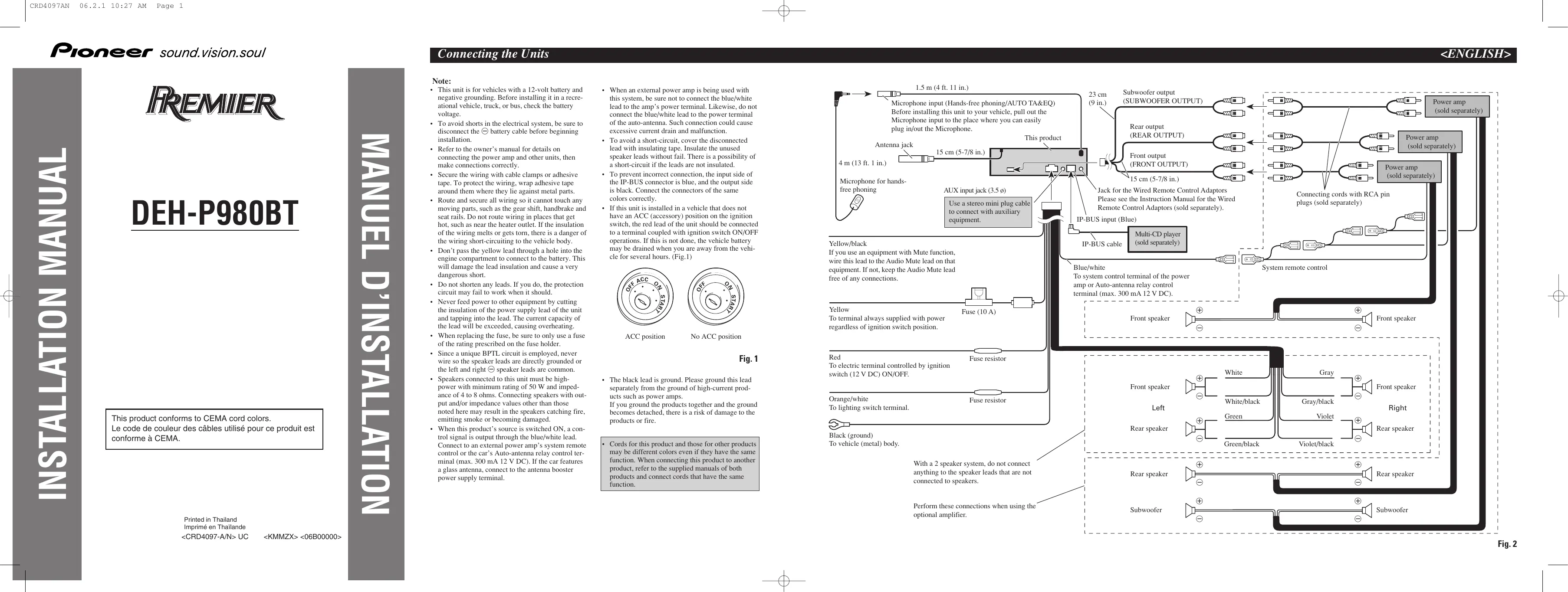
Note:
- This unit is for vehicles with a 12-volt battery and negative grounding. Before installing it in a recreational vehicle, truck, or bus, check the battery voltage.
- To avoid shorts in the electrical system, be sure to disconnect the battery cable before beginning installation.
- Refer to the owner's manual for details on connecting the power amp and other units, then make connections correctly.
- Secure the wiring with cable clamps or adhesive tape. To protect the wiring, wrap adhesive tape around them where they lie against metal parts.
- Route and secure all wiring so it cannot touch any moving parts, such as the gear shift, handbrake and seat rails. Do not route wiring in places that get hot, such as near the heater outlet. If the insulation of the wiring melts or gets torn, there is a danger of the wiring short-circuiting to the vehicle body.
- Don't pass the yellow lead through a hole into the engine compartment to connect to the battery. This will damage the lead insulation and cause a very dangerous short.
- Do not shorten any leads. If you do, the protection circuit may fail to work when it should.
- Never feed power to other equipment by cutting the insulation of the power supply lead of the unit and tapping into the lead. The current capacity of the lead will be exceeded, causing overheating.
- When replacing the fuse, be sure to only use a fuse of the rating prescribed on the fuse holder.
- Since a unique BPTL circuit is employed, never wire so the speaker leads are directly grounded or the left and right speaker leads are common.
- Speakers connected to this unit must be high-power with minimum rating of 50 W and impedance of 4 to 8 ohms. Connecting speakers with output and/or impedance values other than those noted here may result in the speakers catching fire, emitting smoke or becoming damaged.
-
When this product's source is switched ON, a control signal is output through the blue/white lead. Connect to an external power amp's system remote control or the car's Auto-antenna relay control terminal (max. 300 mA 12 V DC). If the car features a glass antenna, connect to the antenna booster power supply terminal.
-
When an external power amp is being used with this system, be sure not to connect the blue/white lead to the amp's power terminal. Likewise, do not connect the blue/white lead to the power terminal of the auto-antenna. Such connection could cause excessive current drain and malfunction.
- To avoid a short-circuit, cover the disconnected lead with insulating tape. Insulate the unused speaker leads without fail. There is a possibility of a short-circuit if the leads are not insulated.
- To prevent incorrect connection, the input side of the IP-BUS connector is blue, and the output side is black. Connect the connectors of the same colors correctly.
- If this unit is installed in a vehicle that does not have an ACC (accessory) position on the ignition switch, the red lead of the unit should be connected to a terminal coupled with ignition switch ON/OFF operations. If this is not done, the vehicle battery may be drained when you are away from the vehicle for several hours. (Fig.1)

ACC position

No ACC position
Fig. 1
- The black lead is ground. Please ground this lead separately from the ground of high-current products such as power amps.
If you ground the products together and the ground becomes detached, there is a risk of damage to the products or fire.
- Cords for this product and those for other products may be different colors even if they have the same function. When connecting this product to another product, refer to the supplied manuals of both products and connect cords that have the same function.

- Before making a final installation of the unit, temporarily connect the wiring to confirm that the connections are correct and the system works properly.
- Use only the parts included with the unit to ensure proper installation. The use of unauthorized parts can cause malfunctions.
- Consult with your nearest dealer if installation requires the drilling of holes or other modifications of the vehicle.
- Install the unit where it does not get in the driver's way and cannot injure the passenger if there is a sudden stop, like an emergency stop.
- The semiconductor laser will be damaged if it overheats, so don't install the unit anywhere hot — for instance, near a heater outlet.
- If installation angle exceeds 60^ from horizontal, the unit might not give its optimum performance. (Fig. 3)

Fig. 3
- When installing, to ensure proper heat dispersal when using this unit, make sure you leave ample space behind the rear panel and wrap any loose cables so they are not blocking the vents.

text_image
Leave ample space 10 cm (3-7/8 in.) 10 cm (3-7/8 in.) DashboardFig. 4
DIN Front/Rear-mount
This unit can be properly installed either from “Front” (conventional DIN Front-mount) or “Rear” (DIN Rear-mount installation, utilizing threaded screw holes at the sides of unit chassis). For details, refer to the following illustrated installation methods.
DIN Front-mount
Installation with the rubber bush (Fig. 5)
Holder
After inserting the holder into the dashboard, then select the appropriate tabs according to the thickness of the dashboard material and bend them. (Install as firmly as possible using the top and bottom tabs. To secure, bend the tabs 90 degrees.)

text_image
Dashboard 182 53 Rubber bush Screw tabs according to the dashboard material (Install as firmly a top and bottom tabs the tabs 90 degreesFig. 5
Removing the unit (Fig. 6) (Fig. 7)

natural_image
Diagram showing a rectangular block being transferred into a rectangular box (no text or symbols present), Frame
To remove the frame, extend top and bottom of the frame outwards in order to unlock it. (When reattaching the frame, point the side with a groove downwards and attach it.)
- It becomes easy to remove the frame if the front panel is released.
Fig. 6

text_image
Insert the supplied ex- into the unit, as show until they click into p- the keys pressed aga- the unit, pull the unitInsert the supplied extraction keys into the unit, as shown in the figure, until they click into place. Keeping the keys pressed against the sides of the unit, pull the unit out.
Fig. 7
DIN Rear-mount
Installation using the screw holes on the side of the unit
- Remove the frame. (Fig. 8)

natural_image
Diagram showing a rectangular block being inserted into a rectangular component with an arrow indicating direction (no text or symbols)Frame
To remove the frame, extend top and bottom of the frame outwards in order to unlock it. (When reattaching the frame, point the side with a groove downwards and attach it.)
- It becomes easy to remove the frame if the front panel is released.
Fig. 8
- Fastening the unit to the factory radio mounting bracket. (Fig. 9) (Fig. 10)
Select a position where the screw holes of the bracket and the screw holes of the head unit become aligned (are fitted), and tighten the screws at 2 places on each side. Use either truss screws (5 × 8 mm) or flush surface screws (5 × 9 mm), depending on the shape of the screw holes in the bracket.

Fig. 9

text_image
Screw Dashboard or Console Factory radio mounting bracketFig. 10
Fixing the front panel
If you do not operate the removing and attaching the front panel function, use the supplied fixing screw to fix the front panel to this unit.

text_image
Fixing screwFig. 11
Installing the microphone for hands-free phoning
Installation notes
- Install the microphone in a position and orientation that will enable it to pick up the voice of the person operating the system.
When installing the microphone on the sun visor
- Install the microphone on the microphone clip. (Fig. 12)

text_image
Microphone for hands-free phoning Microphone clipFig. 12
- Install the microphone clip on the sun visor. (Fig. 13)
With the sun visor up, install the microphone clip. (Lowering the sun visor reduces the recognition rate for voice operations.)

text_image
Microphone clip Clamps Use clamps to secure the lead where necessary inside the vehicle.Fig. 13
When installing the microphone on the steering column
- Install the microphone on the microphone clip. (Fig. 14)

text_image
Fit the microphone lead into the groove. Microphone for hands- free phoning Microphone clipFig. 14
- Install the microphone clip on the steering column. (Fig. 15)

text_image
Double-sided tape Install the microphone clip on the rear side of the steering column. Clamps Use clamps to secure the lead where necessary inside the vehicle.Fig. 15
CAUTION
- It is extremely dangerous to allow the microphone lead to become wound around the steering column or gearstick. Be sure to install the unit in such a way that it will not obstruct driving.
Remarque:
natural_image
Diagram showing a rectangular block being inserted into a rectangular component (no text or symbols)Cadre