
WL-2000 - Security Camera AIRLIVE - Free user manual and instructions
Find the device manual for free WL-2000 AIRLIVE in PDF.


| Product Type | Security Camera |
| Brand | AirLive |
| Model | WL-2000 |
| Dimensions | 120 x 70 x 70 mm |
| Weight | 300 g |
| Power Supply | DC 5V, 2A (via included adapter) |
| Video Resolution | 1920 x 1080 (Full HD) |
| Night Vision | Up to 30 meters with infrared LEDs |
| Field of View | 110° diagonal |
| Motion Detection | Yes, with adjustable sensitivity |
| Two-Way Audio | Built-in microphone and speaker |
| Connectivity | Wi-Fi 802.11 b/g/n (2.4 GHz) |
| Storage | MicroSD card up to 128 GB |
| Weather Resistance | IP65 (outdoor use) |
| Mounting | Wall or ceiling mount included |
| Maintenance | Clean lens with soft, dry cloth |
| Safety | Avoid exposure to water or extreme temperatures |
| Spare Parts | Not available separately; contact support |
| Repairability | Non-user-serviceable; professional repair only |
Frequently Asked Questions - WL-2000 AIRLIVE
User questions about WL-2000 AIRLIVE
0 question about this device. Answer the ones you know or ask your own.
Ask a new question about this device
Download the instructions for your Security Camera in PDF format for free! Find your manual WL-2000 - AIRLIVE and take your electronic device back in hand. On this page are published all the documents necessary for the use of your device. WL-2000 by AIRLIVE.
USER MANUAL WL-2000 AIRLIVE
IR Wireless-G Dual Stream
IP Camera
User's Manual
Declaration of Conformity
We, Manufacturer/Importer
OvisLink Corp.
5F., NO.6, Lane 130, Min-Chuan Rd.,
Hsin-Tien City, Taipei County, Taiwan
Declare that the product
IR Wireless G Dual Stream IP Camera
AirLive WL-2000CAM
is in conformity with
In accordance with 2004/108/EC Directive and 1999/5 EC-R & TTE Directive
Clause Description
EN 301 489-1
EN 301 489-17
EN 300 328
EN 50371
EN 60950-1
CE marking
Electromagnetic compatibility and Radio spectrum Matters (ERM);
Electromagnetic compatibility(EMC) standard for radio equipment And services; Part 17: Specific conditions for Wideband data and HIPERLAN equipment
Electromagnetic compatibility and Radio spectrum matters (ERM); Wideband transmission equipment operating in the 2.4GHz ISM band And using spread spectrum modulation techniques; Part 1: technical Characteristics and test conditions Part2 : Harmonized EN covering Essential requirements under article 3.2 of the R&TTE Directive
Generic standard to demonstrate the compliance of low power Electronic and electrical apparatus with the basic restrictions related to human exposure to electromagnetic field (10MHz – 300GHz) -General public
Safety for information technology equipment including electrical business equipment

Manufacturer/Importer
Signature
Name
Position/ Title
albert Ue
Albert Yeh
Vice President
(Stamp)
Date : 2008/04/08
AirLive WL-2000CAM CE Declaration Statement
| Country | Declaration Country | Declaration | |
| csČesky [Czech] | OvisLink Corp. tímto prohlašuje, že tento AirLive WL-2000CAM je ve shodě se základními požadavky a dalšími příslušnými ustanoveními směrnice 1999/5/ES. | ItLietuvių[Lithuanian] | ŠiuO OvisLink Corp. deklaruoja, kad šis AirLive WL-2000CAM atitinka esminius reikalavimus ir kitas 1999/5/EB Direktyvos nuostatas. |
| daDansk [Danish] | Undertegnede OvisLink Corp. erklærer herved, at følgende udstyr AirLive WL-2000CAM overholder de væsentlige krav og øvrige relevante krav i direktiv 1999/5/EF. | nlNederlands [Dutch] | Hierbij verklaart OvisLink Corp. dat het toestel AirLive WL-2000CAM in overeenstemming is met de essentiële eisen en de andere relevante bepalingen van richtlijn 1999/5/EG. |
| deDeutsch[German] | Hiermit erklärt OvisLink Corp., dass sich das Gerät AirLive WL-2000CAM in Übereinstimmung mit den grundlegenden Anforderungen und den übrigen einschlägigen Bestimmungen der Richtlinie 1999/5/EG befindet. | mtMalti [Maltese] | Hawnhekk, OvisLink Corp, jiddikjara li dan AirLive WL-2000CAM jikkonforma mal-htigijiet essenzjali u ma provvedimenti ohrajn relevanti li hemm fid-Dirrettiva 1999/5/EC. |
| etEesti [Estonian] | Käesolevaga kinnitab OvisLink Corp. seadme AirLive WL-2000CAM vastavust direktiivi 1999/5/EÜ põhinõuetele ja nimetatud direktiivist tulenevatele teistele asjakohastele sätetele. | huMagyar[Hungarian] | Az OvisLink Corporation kijelenti, hogy az AirLive WL-2000CAM megfelel az 1999/05/CE irányelv alapvető követelményeinek és egyéb vonatkozó rendelkezéseinek. |
| enEnglish | Hereby, OvisLink Corp., declares that this AirLive WL-2000CAM is in compliance with the essential requirements and other relevant provisions of Directive 1999/5/EC. | plPolski [Polish] | Niniejszym OvisLink Corp oświadcza, že AirLive WL-2000CAM jest zgodny z zasadniczymi wymogami oraz pozostałymi stosownymi postanowieniami Dyrektywy 1999/5/EC. |
| esEspañol[Spanish] | Por medio de la presente OvisLink Corp. declara que el AirLive WL-2000CAM cumple con los requisitos esenciales y cualesquiera otras disposiciones aplicables o exigibles de la Directiva 1999/5/CE. | ptPortuguês[Portuguese] | OvisLink Corp declara que este AirLive WL-2000CAM está conforme com os requisitos essenciais e outras disposições da Directiva 1999/5/CE. |
| elΕλληνική [Greek] | ME THN ΠΑΡΟΥΣΑ OvisLink Corp. ΔΗΛΩΝΕΙ OTI AirLive WL-2000CAM ΣΥΜΜΟΡΦΩΝΕΤΑΙ ΠΡΟΣ ΤΙΣ ΟΥΣΙΩΔΕΙΣ ΑΠΑΙΤΗΣΕΙΣ ΚΑΙ ΤΙΣ ΛΟΙΠΕΣ ΣΧΕΤΙΚΕΣ ΔΙΑΤΑΞΕΙΣ ΤΗΣ ΟΔΗΓΙΑΣ 1999/5/EK. | sISlovensko[Slovenian] | OvisLink Corp izjavlja, da je ta AirLive WL-2000CAM v skladu z bistvenimi zahtevami in ostalimi relevantnimi določili direktive 1999/5/ES. |
| frFrançais [French] | Par la présente OvisLink Corp. déclare que l'appareil AirLive WL-2000CAM est conforme aux exigences essentielles et aux autres dispositions pertinentes de la directive 1999/5/CE | skSlovensky [Slovak] | OvisLink Corp týmto vyhlasuje, že AirLive WL-2000CAM spĺňa základné požiadavky a všetky prislušné ustanovenia Smernice 1999/5/ES. |
| itItaliano [Italian] | Con la presente OvisLink Corp. dichiara che questo AirLive WL-2000CAM è conforme ai requisiti essenziali ed alle altre disposizioni pertinenti stabilite dalla direttiva 1999/5/CE. | fISuomi [Finnish] | OvisLink Corp vakuuttaa täten että AirLive WL-2000CAM tyyppinen laite on direktiivin 1999/5/EY oleellisten vaatimusten ja sitä koskevien direktiivin muiden ehtojen mukainen |
| lvLatviski [Latvian] | Ar šo OvisLink Corp. deklarē, ka AirLive WL-2000CAM atbilst Direktīvas 1999/5/EK būtiskajām prasībām un citiem ar to saistītajiem noteikumiem. | Íslenska [Icelandic] | Hér með lýsir OvisLink Corp yfir því að AirLive WL-2000CAM er í samræmi við grunnkröfur og aðrar kröfur, sem gerðar eru í tilskipun 1999/5/EC. |
| svSvenska[Swedish] | Härmed intygar OvisLink Corp. att denna AirLive WL-2000CAM står I överensstämmelse med de väsentliga egenskapskrav och övriga relevanta bestämmelser som framgår av direktiv 1999/5/EG. | noNorsk [Norwegian] | OvisLink Corp erklærer herved at utstyret AirLive WL-2000CAM er i samsvar med de grunnleggende krav og øvrige relevante krav i direktiv 1999/5/EF. |
A copy of the full CE report can be obtained from the following address:
OvisLink Corp.
5F, No.6 Lane 130,
Min-Chuan Rd, Hsin-Tien City,
Taipei, Taiwan, R.O.C.
This equipment may be used in AT, BE, CY, CZ, DK, EE, FI, FR, DE, GR, HU, IE, IT, LV, LT, LU, MT, NL, PL, PT, SK, SI, ES, SE, GB, IS, LI, NO, CH, BG, RO, TR
Before You Use this Product
This product has been designed with safety in mind. However, if not used properly, electrical products can cause fires which may lead to serious bodily injury. To avoid such accidents, be sure to heed the following:
Legal Caution
Video and audio surveillance can be forbidden by laws that vary from country to country. Check the laws in your local region before using this product for surveillance purposes.
Heed the safety precautions
Be sure to follow the general safety precautions and the "Operation Notice."
In case of a breakdown
In case of system breakdown, discontinue usage and contact your authorized dealer.
In case of abnormal operation
- If the unit emits smoke or an unusual smell,
- If water or other foreign objects enter the cabinet, or
- If you drop the unit or damage the cabinet:
1 Disconnect the cable and the connecting cables.
2 Contact your authorized dealer or the store where you purchased the product.
Operation Notice - Operating or storage location
Avoid operating or storing the camera in the following locations:
- Extremely hot or cold places (operating temperature: 0^ to +50^ [32 °F to 122°F])
- Exposed to direct sunlight for a long time or close to heating equipment (e.g., near heaters)
- Close to sources of strong magnetism
- Close to sources of powerful electromagnetic radiation, such as radios or TV transmitters
- Locations subject to strong vibration or shock
Ventilation
To prevent heat buildup, do not block air circulation around the device.
Transportation
When transporting the camera, repack it as originally packed at the factory or in materials of equal quality.
Cleaning
- Use a soft, dry cloth to clean the external surfaces of the device. Stubborn stains can be removed using a soft cloth dampened with a small quantity of detergent solution, then wipe dry.
- Do not use volatile solvents such as alcohol, benzene or thinners as they may damage the surface.
AirLive WL-2000CAM User's Manual
TABLE OF CONTENT
CHAPTER 1 INSTALLATION ....3
1-1 INSTALLATION STEPS....3
1-2 PACKAGE CONTENTS....3
CHAPTER 2 USING IP CAMERA VIA MOBILE PHONE....5
2-1 3G MOBILE PHONE VIEWING....5
2-2 2.5G MOBILE PHONE VIEWING ....5
CHAPTER 3 USING IP CAMERA VIA WEB BROWSER....6
CHAPTER 4 SETTING UP WIRELESS CONFIGURATION ....7
CHAPTER 5 HOW TO USE ....8
5-1 ACCESSING THE IP CAMERA 8
5-2 CONFIGURATION OF MAIN MENU....9
5-2-1 Setting....9
5-2-2 Client Setting....9
5-2-3 Image Setup....9
5-2-4 Live View....10
CHAPTER 6 SETTING....11
6-1 BASIC 11
6-1-1 System....11
6-1-2 Camera....13
6-1-3 Network....18
6-1-4 Security......25
6-2 ADVANCE....27
6-2-1 FTP Client....27
6-2-2 SNMP 30
6-2-3 HTTP Event 34
6-2-4 Schedule....35
6-2-5 Motion Detection....36
6-2-6 System Log....37
APPENDIX A – FRAME RATE & BIT RATE TABLE....38
APPENDIX B - STORAGE REQUIREMENT TABLE 40
Chapter 1 Installation
1-1 Installation Steps
Follow these steps to install the WL-2000CAM on your Ethernet:
- Check the package contents against the list below.
- Set the device. See IP Installer User Manual on the available methods.
1-2 Package Contents
| Item | Description |
| IP Camera | WL-2000CAM IP Camera |
| Antenna | Wireless Antenna |
| Power Adapter | Country-specific |
| CD | User Manual / IP Installer and Document |
| Camera Stand | Supplied with mounting screw |
| Printed Document | Quick Installation Guide |
1-3 Overviews
Front & Side:
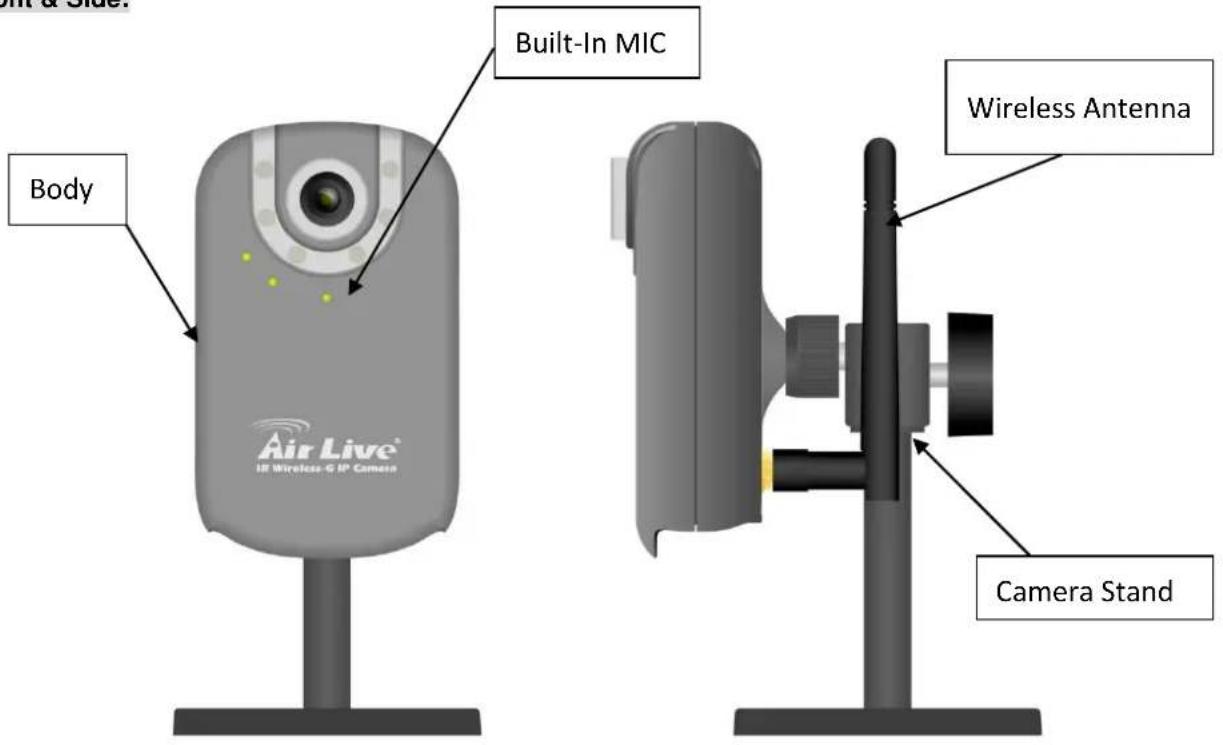
Bottom:
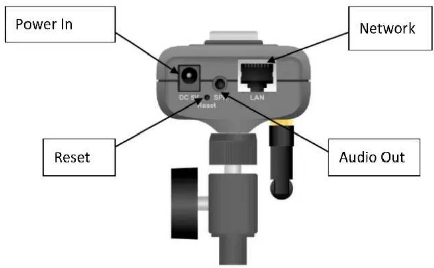
Note
Press the Reset Button to reboot the camera.
Hold the Reset Button for 10 seconds to restore the camera to default
Chapter 2 Using IP Camera via Mobile Phone
To use IP cameras via mobile phones, please make sure your RTSP is set to "ON". (Default is "ON") To change the settings of IP cameras, please see "Settings" for details.
2-1 3G Mobile Phone Viewing
For 3G mobile phone viewing, type "rtsp://
Example: rtsp://100.10.10.1:8554/video.3gp
Note:
- You can also use RTSP clients (RealPlayer, MPlayer, Windows Media Player, QuickTime...etc.) to view RTSP streaming, just type in "rtsp://
2-2 2.5G Mobile Phone Viewing
For 2.5G mobile phone viewing, type "
Chapter 3 Using IP Camera via Web Browser
System Requirement
To use the product normally, we strongly recommend your computer follows our minimum system requirement (Computer level lower than this might cause some problems.)
| Item | Requirements |
| CPU | Pentium 4 1600MHz (or equivalent AMD) |
| Graphic Card | 64MB RAM graphic cards (or equivalent on-board graphic cards) |
| RAM | 512MB |
| Operating System | Windows 98, ME (Please see Note)Windows 2000, 2003, XP, Vista |
| Web Browser | Internet Explorer 6 or later |
Note:
- If you're using Windows 98 or ME, please install IP Installer before using WEB UI to ensure the system runs normally.
- If you can't view the recorded video file (missing video decoder), please install Xvid codec while installing Intelligent IP Installer. (For Windows 98, ME or 2000 server, the codec might not work properly. You'll need to download Xvid codec 1.0 from the internet.
Chapter 4 Setting up Wireless Configuration
This chapter describes how to set up the camera's wireless connection. The wireless connection has to be set up using the Ethernet connection. After correctly setting up the camera, the wireless function can work without the Ethernet connection.
- Connect to the IP Camera using the Ethernet connection. Enter the configuration page (See "Network" chapter for details.)
- Go "Settings -> Basic -> Network -> Wireless", set the Wireless option to "On", and then click on "Refresh".
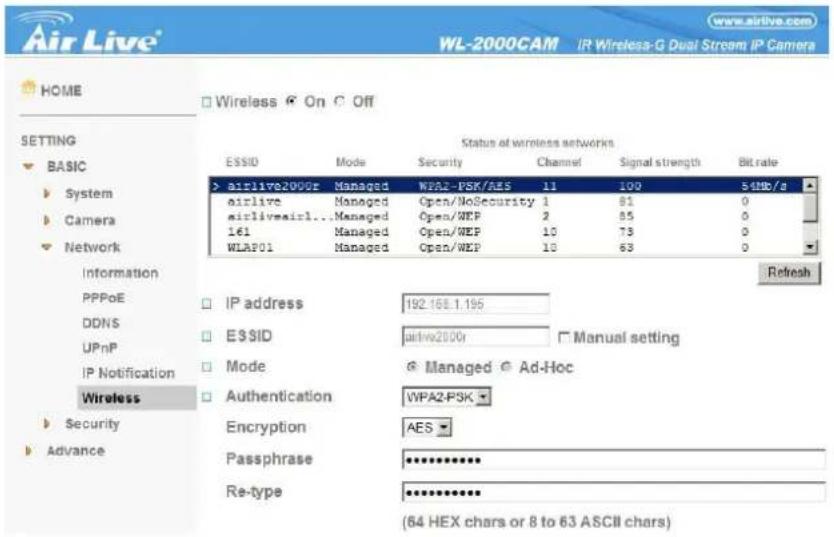
- Choose the wireless AP you wish to connect, enter password if needed. (If you don't know the settings of the wireless AP, please ask your network administrator.)
- If you're using DHCP, the new IP address will show up after wireless setup succeeds.
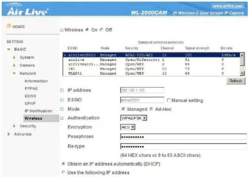
- Connect to the IP Camera with the new IP. You can remove the Ethernet connection now
Chapter 5 How to Use
This chapter introduces how to monitor the image from the device using Microsoft web browser. The IP camera can be used with Microsoft web browsers and Intelligent IP Installer in Windows operation systems. This document focuses on introducing you to Microsoft web browser. The recommended browser for Windows is Internet Explorer 6.0. If you want to know how to use IP camera with Intelligent IP Installer, check Intelligent IP Installer User's Manual in Windows operation systems.
The functions of the device should be set by the Administrator. For further instructions on setting the device, see "Setting the Camera."
5-1 Accessing the IP Camera
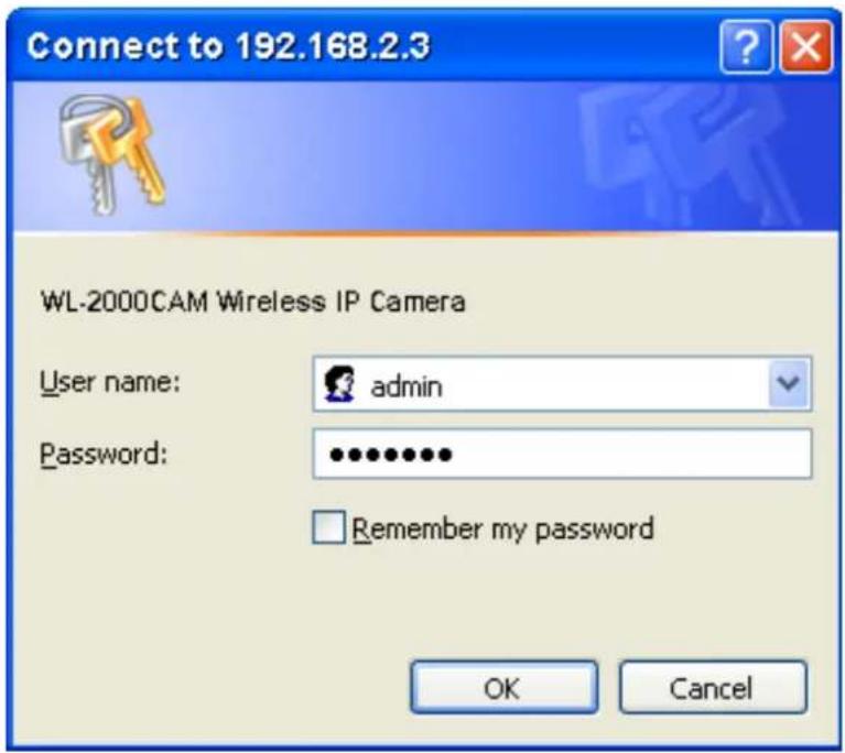
- Start your web browser, and enter the IP address or host name of the IP camera in the Location / Address field of your browser.
Note :
- If you only want to view the video without setting page, enter "http://
- Use the default account "admin" and default password "admin".
Note :
- The default user name "admin" and the password are set at the factory for the administrator. You can change them in the Account Menu under Setting on page 25.
- The monitor image will be displayed in your browser.
5-2 Configuration of Main Menu
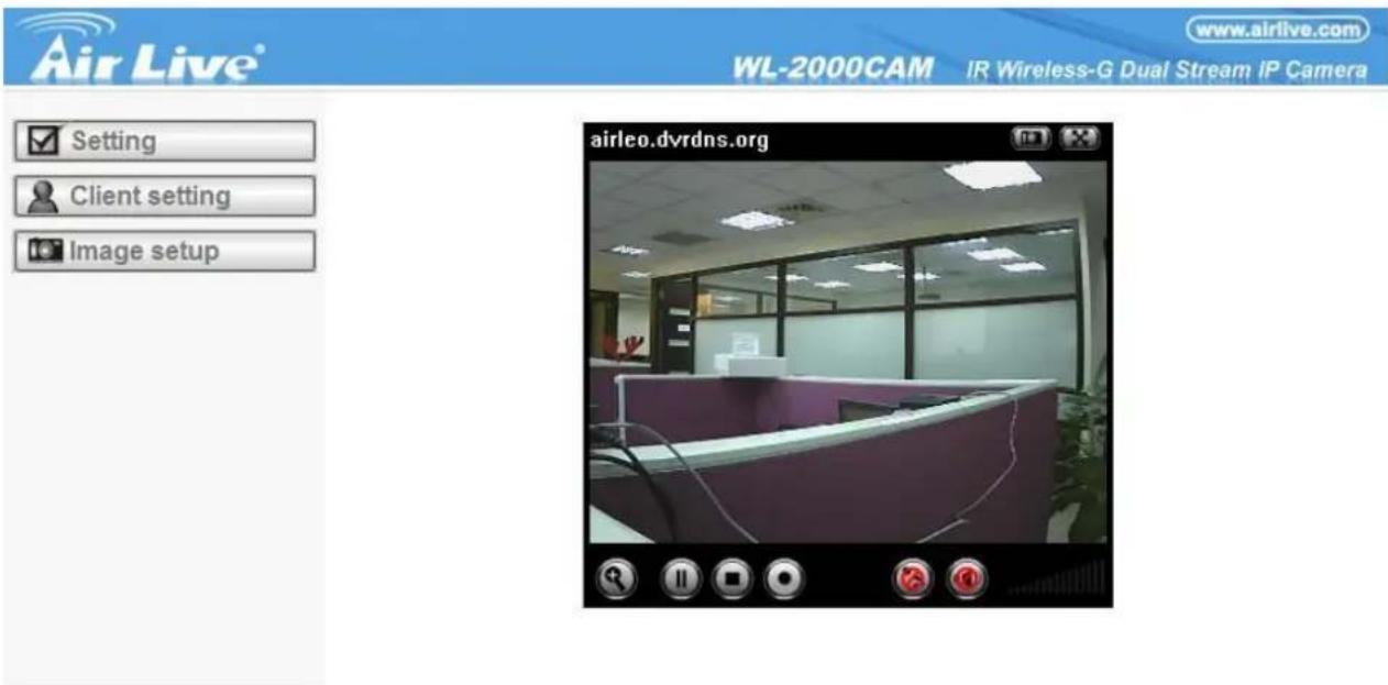
5-2-1 Setting

Setting
This function is only for the Administrator. Click this button to get into the Basic and Advance settings menu.
5-2-2 Client Setting

Client setting
Mode: Click on the pull-down box to choose between MPEG4 and MJPEG video compression mode.
Note : MJPEG streaming is unavailable if RTSP mode is ON.
View Size: Select the desired display image resolution to 640X480 or 320X240.
Protocol: Select the transferring protocol from TCP, UDP, HTTP and Multicast.
Video Buffer: Turn the Video Buffer function On/Off. The Video Buffer function makes the streaming more smoothly in unsteady network environment, but might cause a little delay in live viewing.
5-2-3 Image Setup

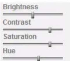
You can use the tool bar to optimize video brightness, contrast, and saturation.
5-2-4 Live View
Snapshot:
You can capture a still image shot by the camera and save it in your computer.
- Press and a snapshot window will appear.
- Click "Save" to save the picture in your computer.
- Click "Close" to return to the view page.
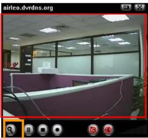
Zoom in/out the image via the monitor window.
natural_image
Interior view of an office with a purple desk and large windows (no visible text or symbols)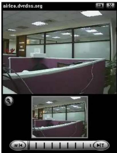
natural_image
Interior view of an office with cubicles and large windows (no visible text or symbols)- Click to display the digital zoom in window.
- Pull the to adjust the digital zoom range, and it will be shown
on the above window.
- You can use the left click of your mouse to move the □ to any where on the window.
Audio buttons :

: Speakers turned on.

: Microphone turned on.

Speakers turned off.

Microphone turned off.
• : Volume control bar.
Note :
- It means the speakers of your computer are turned on to transmit the sounds from the connected IP camera(s). Similarly, means you can broadcast to the connected IP camera(s) via the Ethernet using your microphone.
Video play buttons:

: Pause the current video

deo.

: Stop the current video.

current video.
AirLive WL-2000CAM User's Manual
Chapter 6 Setting
6-1 Basic
Click on the "Basic" folder to display the sub folders, including System, Camera, Network, and Security.
6-1-1 System
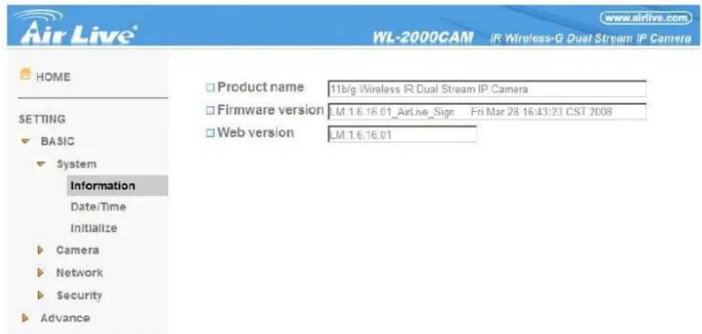
Information
The Information page provides you with product factory information, including Product name, Firmware version, and Web version.
Day & Time
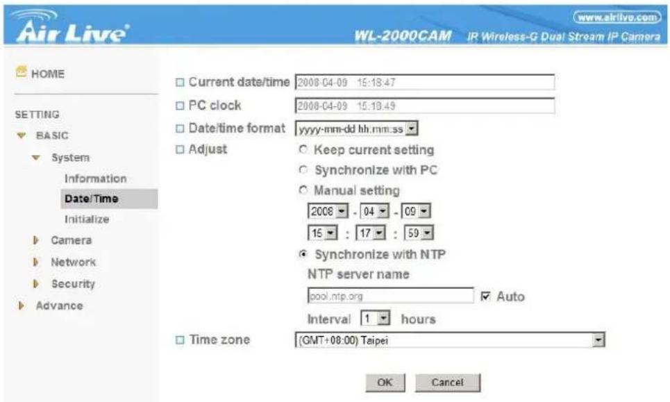
Current date & time : This displays the current date and time of the device.
PC clock : This displays the date and time of the monitoring PC clock.
Date & time format : Click the pull-down box to select among different time display formats, including yyyy-mm-dd hh:mm:ss (year-month-day hour:minute:second), mm-dd-yyyy hh:mm:ss (month-day-year hour:minute:second), and dd-mm-yyyy hh:mm:ss (day-month-year hour:minute:second).
Adjust : Select one of four time adjusting modes.
Keep current setting : Select this mode to keep the current date and time of the device.
Synchronize with PC : Select this mode to make the date and time of the device the same as the monitoring PC.
Manual setting : Select this mode to manually adjust the date & time of the device.
Synchronize with NTP : Specify the NTP server name and the Refresh Interval to synchronize the date and time of the device with those of the time server, known as the NTP (Network Time Protocol) server.
Note:
- The NTP server (Network Time Protocol) is the time server which is an Internet standard protocol (built on top of TCP/IP) that assures accurate synchronization to the millisecond of computer clock times in a network of computers.
NTP server name : Type the host name or IP address of the NTP server, up to 64 characters.
Time zone: Select the time zone and time difference from Greenwich Mean Time in the area where the device is installed from the pull-down box.
Initialize
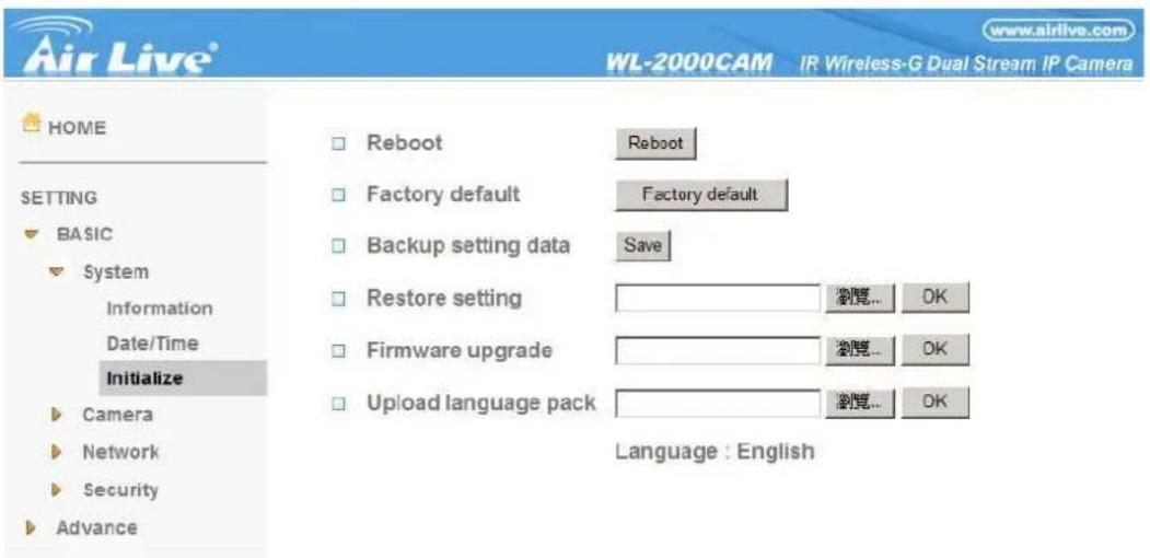
Reboot : Click this button to reboot the device. A confirmation dialogue will appear. Click OK to proceed. It takes about two minutes to reboot the device.
Factory default : Click this button to reset the device to the factory default settings. A confirmation dialogue will appear. Click OK to proceed; the network indicator on the device will start to blink. After completing adjustments to the default settings, the device will reboot automatically. Do not turn off the device until the device reboots.
Backup setting data : Save the setting data of the device to a file. Click Save, and follow the instructions on the
AirLive WL-2000CAM User's Manual
browser to save the setting data file to your specified location.
Restore setting : Load the saved setting data of the device. Click Browse and select the file in which the setting data is stored. Click OK, and the device is adjusted according to the loaded data and restarted.
Firmware update : Upgrade the device software. Click Browse and select the file for upgrading. A confirmation dialogue will appear. Click OK to start upgrading. The device will reboot upon completion.
Note:
- Use only upgraded files that are special for this device. Problems may occur otherwise.
- Do not turn off the device power or disconnect the network until the upgrading is completed.
Upload language pack : Upgrade the device language pack. Click Browse and select the file for upgrading. A confirmation dialogue will appear. Click OK to start upgrading. The upgrade is applied immediately. The default language is "English."
6-1-2 Camera
6-1-2-1 General
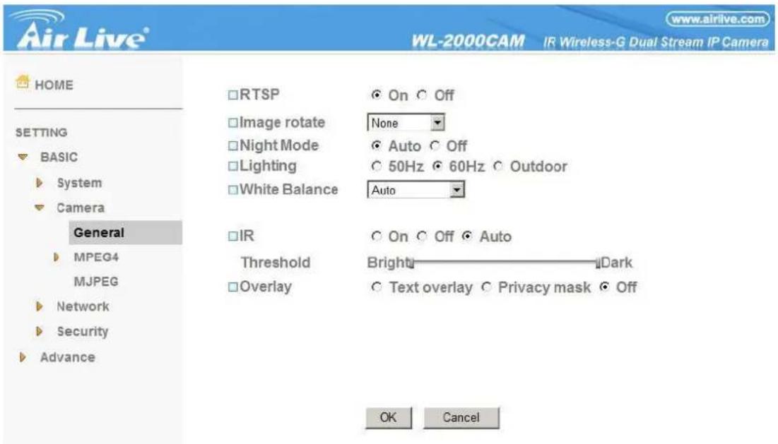
RTSP: Switch the RTSP streaming On/Off.
Note :
- RTSP: Real Time Streaming Protocol. RTSP is supported by most of the media clients. (RealPlayer, Media Player, QuickTime, etc...)
Image Rotate : Enables user to mirror or flip the display screen.
Night Mode : Turn Night Mode ON/OFF.
Lighting : Choose the lighting environment among 50Hz, 60Hz and Outdoor.
White Balance : Choose the White Balance to Auto, Fluorescent, Incandescent and Black&White.
IR: Turn LEDs ON/OFF, or Select auto mode. In auto mode, provide threshold adjustment for LEDs auto-ON and auto-OFF respectively.
AirLive WL-2000CAM User's Manual

Threshold




Overlay : Select to add Text Overlay or Privacy Mask on/off the display screen.
Text Overlay : Enables users to see some information on the display screen, including Date/Time and user-defined text. You can also change the background color.
Privacy Mask : Enables users to conceal an area of the video image.
6-1-2-2 MPEG4
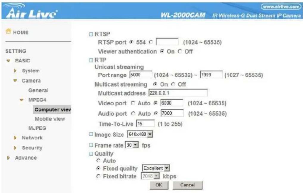
Computer View
RTSP (If RTSP mode is ON)
RTSP port: Specify the transmission port number of RTSP streaming video. Default value is 554.
Viewer authentication: If the viewer authentication is ON, users viewing through RTSP will be requested to key-in username and password.
RTP (If RTSP mode is ON)
Unicast streaming:
Unicast streaming Video/Audio port range: Specify the transmission port range of RTP streaming video. RTP will select a port randomly from the range.
Multicast streaming:
Multicast address: Specify the multicast server address.
Video / Audio Port: Specify the transmission port number of the video data. Specify an even number from 1024
AirLive WL-2000CAM User's Manual
to 65534.
Time-To-Live: Set the maximum TTL that multicast can pass through.
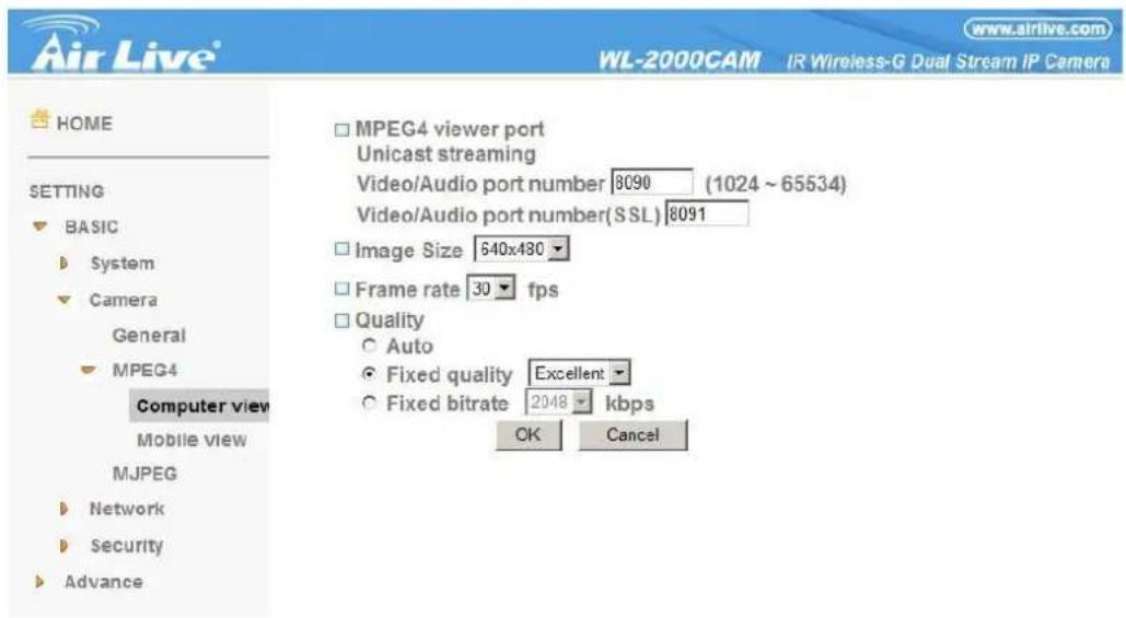
MPEG4 viewer port (If RTSP mode is OFF)
Unicast streaming Video/Audio port number: Specify the transmission port number of the video data. It is initially set to 8090. Specify an even number from 1024 to 65534.
Image Size : Specify the image size the network camera transmits. You can choose among 704 × 480, 352 × 240 and 176 × 120 for NTSC mode and 704 × 576, 352 × 288 and 176 × 144 for PAL mode.
Frame rate : Set the frame rate of the MPEG4 image. Selectable values are 5, 10, 15, 20, 25, 30 fps. The unit "fps" stands for "frames sent per second".
Quality
Auto : The quality and bit rate will be automatically decided according to the frame rate.
Fixed Quality : The selectable values are Medium, Standard, Good, Detailed and Excellent.
Fixed Bit rate: Set the bit rate of MPEG4 image transmission for a line. Selectable values are 64, 128, 256, 384, 512, 768, 1024, 1280, 1536 and 2048 kbps.
Note :
- The selected frame rate and bit rate are a tentative value. The actual frame rate and bit rate may be different according to the image size, the shooting scene or the network condition.
Mobile View
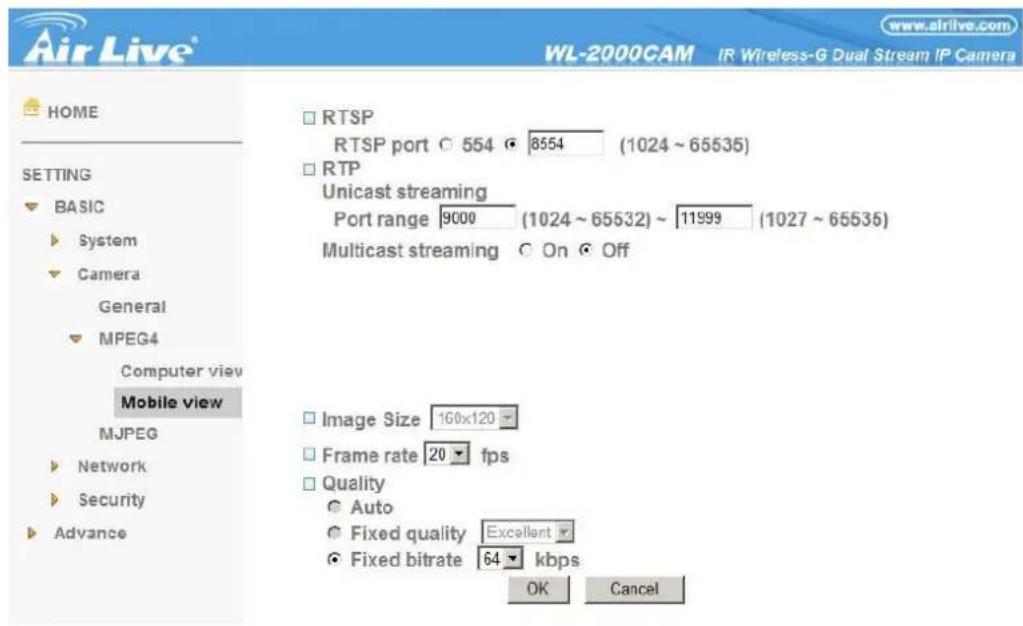
RTSP (If RTSP mode is ON)
RTSP port: Specify the transmission port number of RTSP streaming video. Default value is 8554.
RTP (If RTSP mode is ON)
Unicast streaming:
Unicast streaming Video/Audio port range: Specify the transmission port range of RTP streaming video. RTP will select a port randomly from the range.
Multicast streaming:
Multicast address: Specify the multicast server address.
Video / Audio Port: Specify the transmission port number of the video data. It is initially set to 10000 and 11000. Specify an even number from 1024 to 65534.
Time-To-Live: Set the maximum TTL that multicast can pass through.
Image Size: The Image size of Mobile view is fixed at 176x120.
Frame rate : Set the frame rate of the MPEG4 image. Selectable values are 5, 10, 15, 20 fps. The unit "fps" stands for "frames sent per second".
Quality
Fixed Bit rate : Set the bit rate of MPEG4 image transmission for a line. Selectable values are 64, 32, and 16kbps.
6-1-2-3 MJPEG
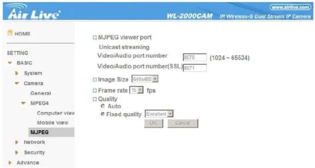
Note :
- MJPEG settings are unavailable if the RTSP mode is ON, which means the MJPEG streaming is closed.
MJPEG viewer port
Unicast streaming Video/Audio port number: Specify the transmission port number of the video data. It is initially set to 8070. Specify an even number from 1024 to 65534.
Note :
- Unicast streaming : Specify the transmission port number of the video data and audio data used when UDP (Unicast) is selected with the TCP/UDP transmission switching icon in the main viewer.
Image Size : Specify the image size the network camera transmits. You can choose among 704 × 480, 352 × 240 and 176 × 120 for NTSC mode and 704 × 576, 352 × 288 and 176 × 144 for PAL mode.
Frame rate : Set the frame rate of the MJPEG image. Selectable values are 5, 10, 15 fps. The unit "fps" stands for "frames sent per second".
Quality
Auto : The quality will be automatically decided.
Fixed quality : The selectable values are Medium, Standard, Good, Detailed and Excellent.
6-1-3 Network
6-1-3-1 Information
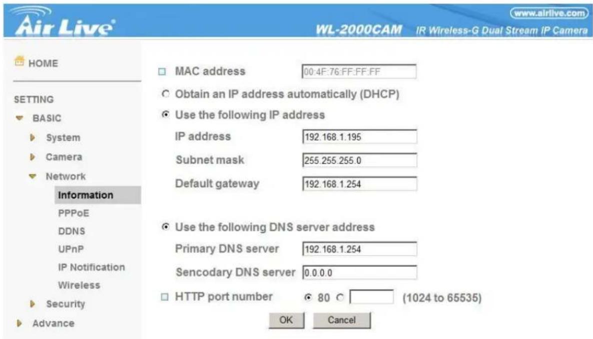
MAC address : Display the MAC address of the device.
Obtain an IP address automatically (DHCP) : If a DHCP server is installed on the network, to select this while the IP address is assigned by the DHCP server.
Note :
- When you set Obtain an IP address automatically (DHCP), make sure that the DHCP server is working on the network.
Use the following IP address : Select this when a fixed IP address is set.
IP address : Enter the IP address of the device.
Subnet mask : Enter the subnet mask.
Default gateway : Enter the default gateway.
Use the following DNS server address : Select this when you set the fixed address as the IP address of DNS server.
Primary DNS server : Enter the IP address of the primary DNS server.
Secondary DNS server : Enter the IP address of the secondary DNS server, if necessary.
HTTP port number : Select 80 in general situations. If you want to use a port number other than 80, select the text box and enter a port number between 1024 and 65535.
Note :
- When you have set the HTTP port number to a number other than 80 on the Network setting page or in the Setup Program, access the device by typing the IP address of the device on the web browser as follows:
Example: when HTTP port number is set to 2000 □ http://192.168.1.100:2000/
6-1-3-2 PPPoE
Use this when you connect the device through PPPoE (Point-to-Point Protocol over Ethernet). PPPoE connection is the protocol that is widely used in xDSL (digital affiliate line such as ADSL, VDSL or SDSL) as the authentication and connection system.
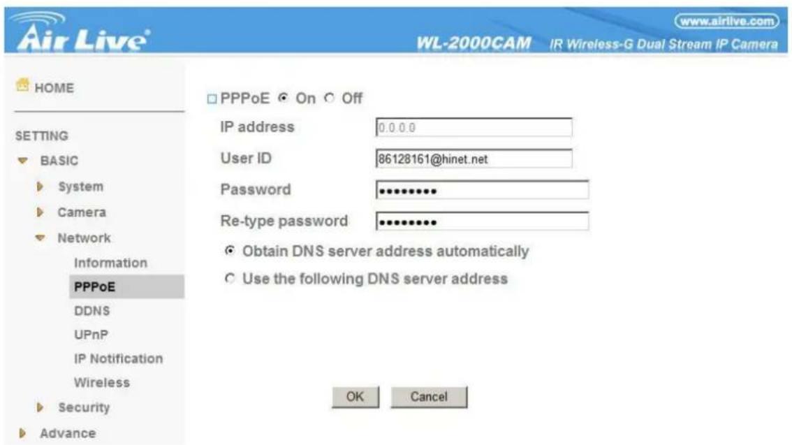
IP address : The IP address obtained at the PPPoE connecting with network.
User ID : Enter the user ID for authentication necessary for PPPoE connections. Type it up to 64 characters.
Password : Enter the password for authentication necessary for PPPoE connections. Type it up to 32 characters.
Re-type password : Re-type the password to confirm.
Obtain DNS server address automatically : Select this to obtain the address of DNS server automatically.
Use the following DNS server address : Select this when you set the fixed address as the IP address of DNS server.
Primary DNS server : Enter the IP address of the primary DNS server.
Secondary DNS server : Enter the IP address of the secondary DNS server.
6-1-3-3 DDNS
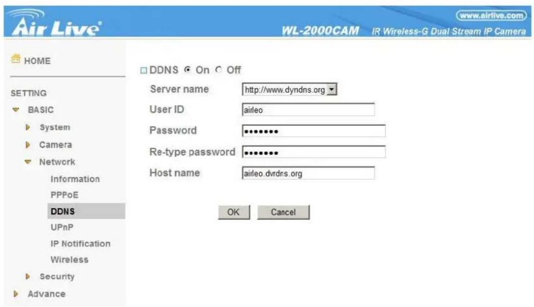
Server name : Choose the DDNS Server from the list.
User ID : Enter the user ID for authentication necessary for DDNS connections. Type it up to 64 characters.
Password : Enter the password for authentication necessary for DDNS connections. Type it up to 32 characters.
Re-type password : Re-type the password to confirm.
Host name : Enter the host name that is registered to the DDNS server.
Note :
- When you want to use DDNS function, you need to register an account in DDNS server first.
6-1-3-4 UPnP
The device includes support for UPnP, which is enabled by default. If also enabled on your computer, the device will automatically be detected and a new icon will be added to "My Network Places." It provides port forwarding for opening a port in a router or firewall in a private network in order to let a party from the outside world contact a user inside.
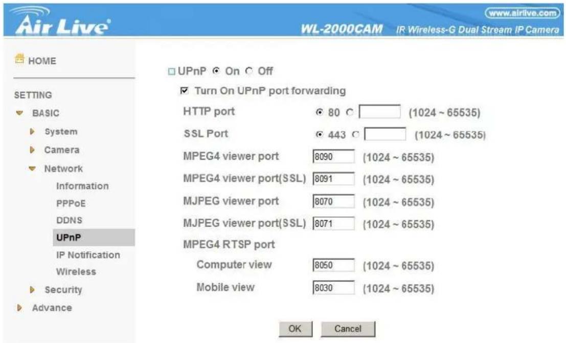
HTTP port : Enter the HTTP port number and default HTTP port is 80.
SSL port: Enter the SSL port number and default SSL port is 443.
MPEG4 viewer port : Enter the MPEG4 viewer port number and default MPEG4 viewer port is 8090.
MPEG4 viewer port (SSL): Enter the MPEG4 SSL viewer port and default is 8091.
MJPEG viewer port : Enter the MJPEG viewer port number and default MJPEG viewer port is 8070.
MJPEG viewer port (SSL): Enter the MPEG4 SSL viewer port and default is 8071.
MPEG4 RTSP port: Enter the MPEG4 RTSP port, default value is 8050 for computer view, 8030 for mobile view.
6-1-3-5 IP Notification
When network notify type is set to On, you can send an e-mail notification of the completion of the network setting.
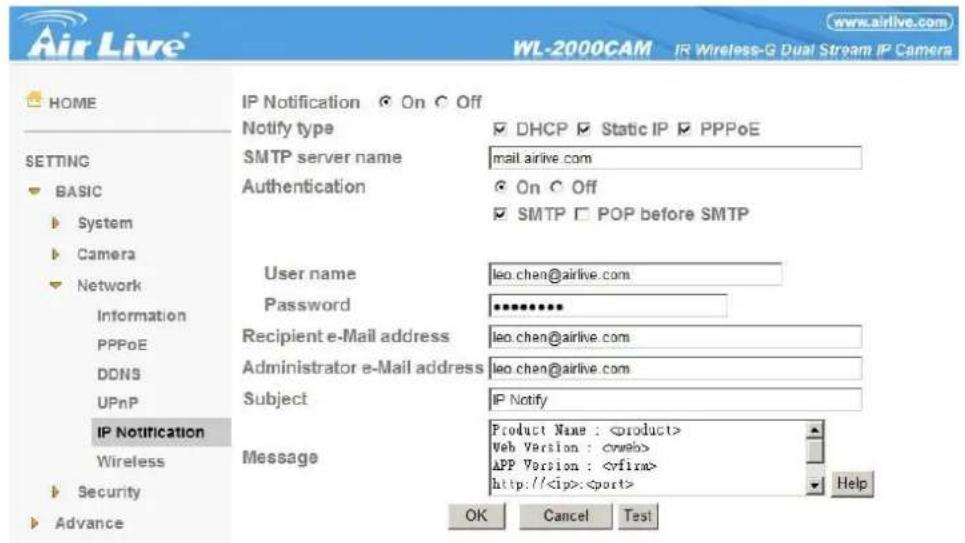
Notify type : Select type of DHCP, Static IP and PPPoE will notify.
SMTP server name : Type the SMTP server name up to 64 characters, or the IP address of the SMTP server.
Authentication : Select the authentication required when you send an email.
Off: Select if no authentication is necessary when an email is sent.
On: When authentication is necessary an e-mail is sent, select one of the authentication methods from the followings.
SMTP: Select if SMTP authentication is necessary when an e-mail is sent.
POP before SMTP: Select if POP before SMTP authentication is necessary when an e-mail is sent.
Note :
- When you set to On, be sure to select either or both SMTP or/and POP before SMTP.
POP server name : It is necessary when the POP before SMTP is selected in Authentication. Type the POP (receiving mail) server name up to 64 characters, or type the IP address of the POP server. This setting is necessary when the SMTP server which sends e-mails performs authentication using the POP user account.
User name, Password: Type the user name and Password of the user who has the mail account. This setting is necessary when the SMTP server which sends e-mails performs authentication.
Recipient e-mail address : Type the recipient e-mail address up to 64 characters. You can specify up to three recipient e-mail addresses.
Administrator e-mail address : Type the Administrator e-mail address up to 64 characters. This address is used for reply mail and sending system messages from the SMTP server.
Subject : Type the subject/title of the e-mail up to 64 characters. With respect to mail which is sent according to the IP notification.
Message
Type the text of the e-mail up to 384 characters. Default value provides network information including IP, Port, MAC, Model, Firmware Version and Web Version.
AirLive WL-2000CAM User's Manual
6-1-3-6 Wireless
Wireless settings must be the same as the access point or ad hoc device. When changing the settings they should always be made first in the camera and then in the wireless access point. This ensures that the camera is always accessible when making changes.
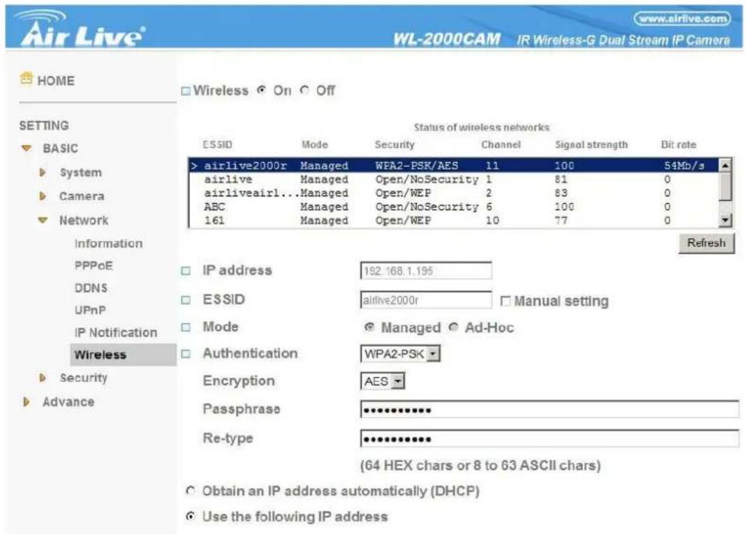
Status of Wireless Networks
This list is the result of a network scan. Access points with a disabled SSID Broadcast will not appear unless the camera is linked to it. The network that is currently linked to is shown in blue. A network using unsupported security is shown in grey. The following information is provided:
- ESSID - The name of a wireless network (or ad-hoc device). If the same name occurs several times this means that several access points for that network were found. The camera cannot be configured to only associate with one particular access point.
- Mode - Shows if the network type is Master (access point or router) or Ad hoc (another client).
•Security - Shows which type of security the network uses. See below for the security types supported by the camera. - Channel - Shows the wireless channel currently in use.
•Signal strength - Shows the signal strength. - Bit rate - Shows the bit rate in Mbit/s. This can only be shown for the access point currently in use. Note that the bit rate shown is the current rate, and that this value may vary over time.
Wireless Settings
These settings control how the camera interacts with the wireless network. Apart from identifying the wireless network, it is also possible to enable wireless encryption.
IP Address – This displays blank, 0.0.0.0 or IP Address. When it's blank, the camera doesn't establish physical link with access point yet. The 0.0.0.0 means that physical link was established but trying to get IP address.
When it displays IP address, then user can use wireless network.
ESSID - This is the name of the wireless network the camera is configured for. The field accepts up to 32 alphanumeric characters. The name must be exactly the same as that used in the wireless access point or the connection will not be established.
Leaving this field blank means the camera will attempt to access the nearest open network.
Note: ESSID is sometimes written as SSID.
Mode - Setting this to Managed means the camera will attempt to access the nearest open access point. The Ad hoc option allows the camera to connect to other wireless devices (clients).
Note: WEP is the only available encryption method for Ad hoc setting (see below).
Authentication - This has four authentication options:
•WPA2-PSK
•WPA-PSK
•Open
•Shared Key
Encryption - This has four authentication options:
•For WPA-/ WPA2-PSK
•TKIP
•AES
- For Open/ Shared Key
•WEP
- No security
WPA-/WPA2-PSK (Wi-Fi Protected Access - Pre-Shared Key) The camera uses a pre-shared key (PSK) to initiate WPA security. The pre-shared key is entered on the access point and on each device on the wireless network. The key can be entered either as Manual hex, as 64 hexadecimal (0-9, A-F) characters, or as a passphrase, using 8 to 63 ASCII characters. The access point keeps out unauthorized users by requiring the key to communicate.
WEP (Wired Equivalent Protection) The original security standard used in wireless networks that provides a minimal level of security that can deter minor trespasses. The administrator can select the key length among 64 or 128 bits. 64bits is the default setting.
AirLive WL-2000CAM User's Manual
6-1-4 Security
6-1-4-1 Account
The device default account and password setting is "admin/admin". That means everyone might access the device including the configuration as long as the IP address is known. It is necessary to assign a password if the device is intended to be accessed by others. Use this menu to set the user names and passwords of Administrator and up to 9 different users (User 1 to User 9), and the access right of each user.
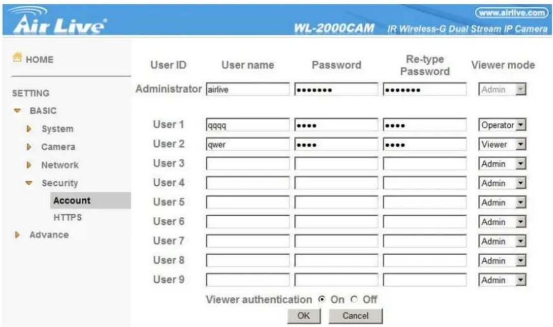
User name : Set a user name between 5 and 16 characters.
Password : Set a password between 5 and 16 characters.
Re-type password : Re-type the password to confirm.
Viewer Mode : Set a user to Admin, Operator or Viewer mode.
Viewer authentication : Allows any viewer direct access to Live View.
6-1-4-2 HTTPS
HTTPS is a URI scheme used to indicate a secure HTTP connection. It is syntactically identical to the http://scheme normally used for accessing resources using HTTP. Using an https: URL indicates that HTTP is to be used, but with a different default TCP port (443) and an additional encryption/authentication layer between the HTTP and TCP. You can use the IP camera through HTTPS easily by using https:// instead of http://.
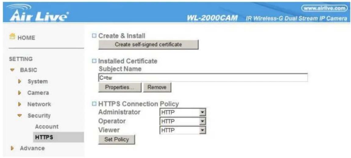
To use the HTTPS encryption, please set up "Create self-signed certificate" for the first time you use the HTTPS function, then set up the connection policy for different users, and click "Set Policy" to apply the settings.
Create & Install: Create a self-signed certificate for HTTPS to recognize.
Installed Certificate: Display or remove the properties of the installed certificate.
HTTPS Connection Policy: Set HTTPS connection policy for different level of users.
6-2 Advance
6-2-1 FTP Client
Use this menu to set up for capturing and sending images to an FTP server. By using FTP client function, you can send the image and audio file which has been shot and recorded linked with the external sensor input or with the built-in motion detection function to FTP server. FTP client setting menu is composed of two tabs,
General, Alarm sending and Periodical sending.
6-2-1-1 General
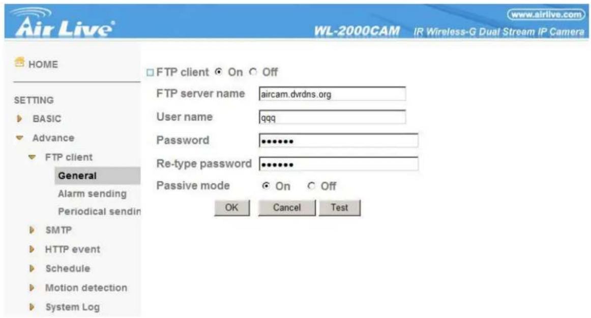
FTP client function : To activate the FTP client function, select On. The FTP client setting page appears. When you do not wish to use the FTP client function, select Off.
Note :
- The frame rate and operability on the main viewer may decrease while a file is being transmitted by the FTP client function.
FTP server name: Type the FTP server name to upload still images up to 64 characters, or the IP address of the FTP server.
User name : Type the user name for the FTP server.
Password : Type the password for the FTP server.
Retype password : To confirm the password, type the same characters as you typed in the Password box.
Passive mode : Set whether you use the passive mode of FTP server or not when connecting to FTP server.
Select On to connect to FTP server using the passive mode.
6-2-1-2 Alarm Sending
Set to forward the image and audio file to the specified FTP server linked with the alarm detection by the external sensor input or by the built-in motion detection function. Select On to send the image and audio file to FTP server linked with the alarm detection.
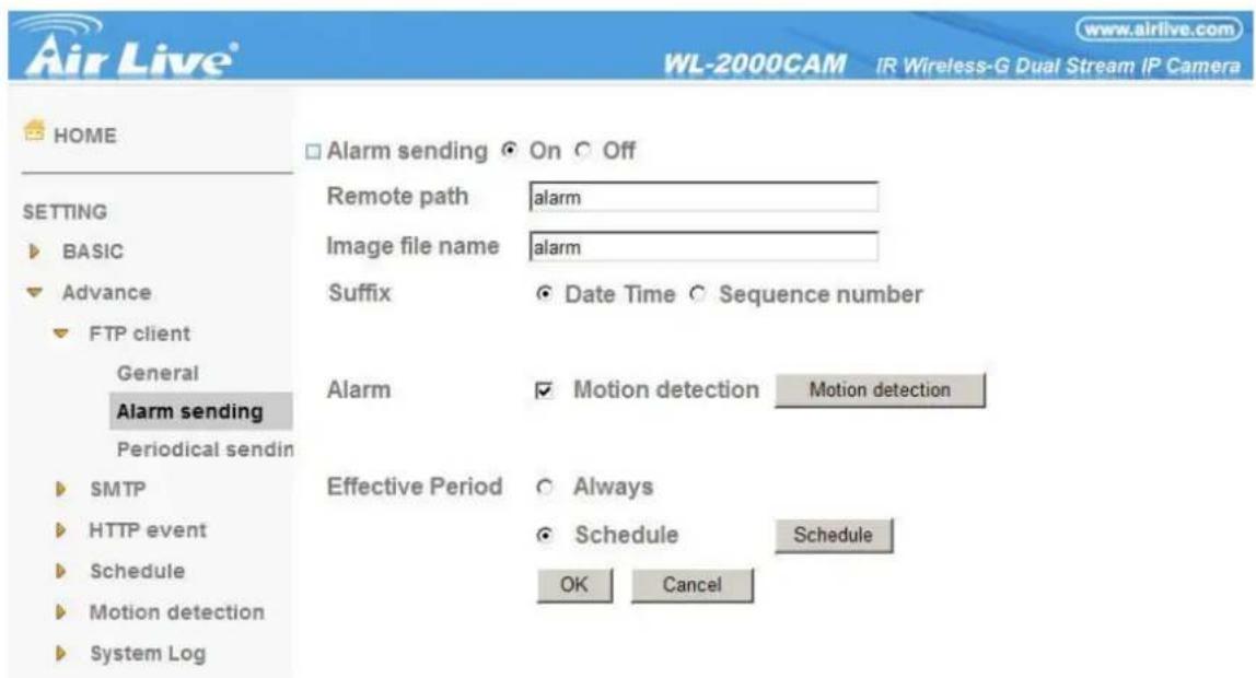
Remote path : Type the path to the destination in FTP server up to 64 characters.
Image file name : Type the file name you want to assign to the images when sending to the FTP server. You can use up to 10 alphanumeric characters, - (hyphen) and _ (underscore) for naming.
Suffix : Select a suffix to add to the file name:
Date & time: The date & time suffix is added to the Image file name. The date/time suffix consists of lower two-digits of year (2 digits), month (2 digits), date (2 digits), hour (2 digits), minute (2 digits), second (2 digits), and consecutive number (2 digits), thus 14-digit number is added to the file name.
Sequence number: A consecutive number of 10 digits between 0000000001 and 4294967295 and two fixed digits 00 are added to the Image file name.
Motion Detection : Click it on for using Motion Detection function as a sensor. You can set the motion detection function page.
Effective period : Set the period when the periodical sending is effective.
Always : The periodical sending is always effective.
Schedule : You can specify the period when the periodical sending is effective in the schedule setting in the other section. Click Schedule and the setting menu for the effective period is displayed.
6-2-1-3 Periodical Sending
You can set to send an image file to FTP server periodically by selecting On to send the image file to FTP server linked with setting period.
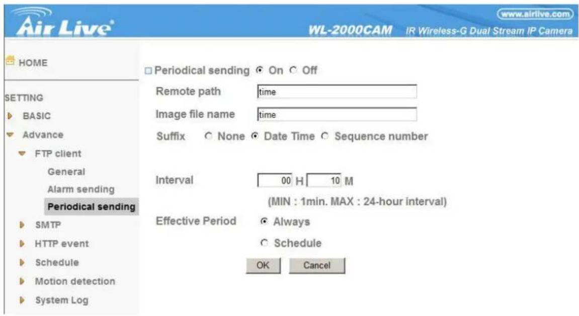
Remote path : Type the remote path up to 64 characters.
Image file name : Type the file name of the image sent to FTP server up to 10 alphanumeric characters, - (hyphen) and _ (under score).
Suffix : Select a suffix to be added to the file name sent to FTP server.
None : The name of the sent file will be the Image file name.
Date & time : The date & time suffix is added to the Image file name. The date & time suffix consists of lower two-digits of year (2 digits), month (2 digits), date (2 digits), hour (2 digits), minute (2 digits) and second (2 digits), and consecutive number (2 digits), thus 14-digit number is added to the file name.
Sequence number : A consecutive number is added to the Image file name.
Sequence number clear : Click Clear and the suffix of the sequence number returns to 1.
Interval : Set the periodical sending is effective interval. Min value is 1 min and Max value is 24 hours.
Effective period : Set the period when the periodical sending is effective.
Always : The periodical sending is always effective.
Schedule : You can specify the period when the periodical sending is effective in the schedule setting in the other section. Click Schedule and the setting menu for the effective period is displayed.
6-2-2 SNMP
Set the SMTP menu when you want to send an image via e-mail. By using Mail (SMTP) function, you can send a mail with attached image which has been shot linked with the external sensor input or with the built-in motion detection function. The image file can also be sent periodically. E-mail (SMTP) setting menu is composed of three tabs, General, Alarm sending and Periodical sending.
6-2-2-1 General
Select On when you use the SMTP function. The common setting options are displayed below. If you do not wish to use the e-mail (SMTP) function, select Off and click OK.
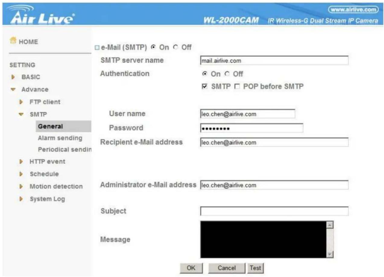
Note :
- During transmission of an image file via mail, the frame rate and operation performance of the monitor image of the main viewer decline.
- While the camera video mode is set to MPEG4, the image of the composite video signal output from the video output connector of the camera may be distorted during mail transmission.
- You cannot send an audio file by using the mail sending function.
SMTP server name : Type the SMTP server name up to 64 characters, or the IP address of the SMTP server.
Authentication : Select the authentication required when you send an e-mail.
Off: Select if no authentication is necessary when an e-mail is sent.
On: When authentication is necessary an e-mail is sent, select one of the authentication methods from the
AirLive WL-2000CAM User's Manual
followings.
SMTP: Select if SMTP authentication is necessary when an e-mail is sent.
POP before SMTP: Select if POP before SMTP authentication is necessary when an e-mail is sent.
Note :
- When you set to On, be sure to select either or both SMTP or/and POP before SMTP.
POP server name : It is necessary when the POP before SMTP is selected in Authentication. Type the POP (receiving mail) server name up to 64 characters, or type the IP address of the POP server. This setting is necessary when the SMTP server which sends e-mails performs authentication using the POP user account.
User name, Password : Type the user name and Password of the user who has the mail account. This setting is necessary when the SMTP server which sends e-mails performs authentication.
Recipient e-mail address: Type the recipient e-mail address up to 64 characters. You can specify up to three recipient E-mail addresses.
Administrator e-mail address : Type the Administrator e-mail address up to 64 characters. This address is used for reply mail and sending system messages from the SMTP server.
Subject : Type the subject/title of the e-mail up to 64 characters. With respect to mail which is sent according to the alarm detection when Alarm sending of the alarm tab is set to On, the characters standing for the sensor type added to the subject.
Message : Type the text of the e-mail up to 384 characters. (A line break is equivalent to 2 characters.)
6-2-2-2 Alarm Sending
Set to send the mail with connection to the alarm detection by the external sensor input or by the built-in motion detection function.
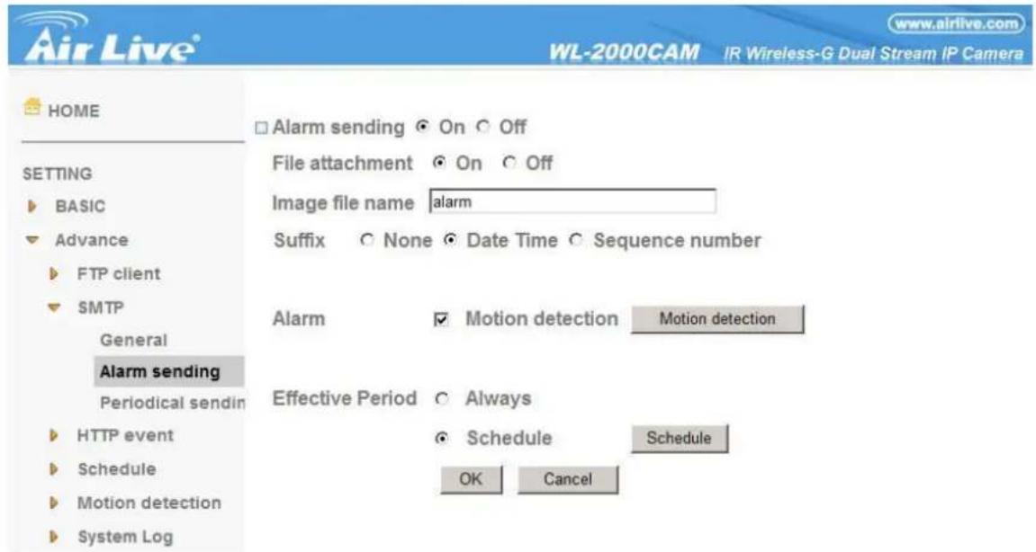
Alarm sending : Select On to set to send mail with connection to the alarm detection.
File attachment : Set whether an image file is attached to the mail sent or not. When On is selected, the image file made by the settings below is attached. When Off is selected, only the message is sent.
Image file name : Type the file name you want to assign to the image to attach a mail. You can use up to 10 alphanumeric, - (hyphen) and _ (underscore) for naming.
Suffix : Select a suffix to add to the file name:
None: No suffix is added. The Image file name is assigned to the image to be sent via an e-mail.
Date & time: The date & time suffix is added to the Image file name. The date/time suffix consists of lower two-digits of year (2 digits), month (2 digits), date (2 digits), hour (2 digits), minute (2 digits), second (2 digits), and consecutive number (2 digits), thus 14-digit number is added to the file name.
Sequence number: A consecutive number of 10 digits between 0000000001 and 4294967295 and two fixed digits 00 are added to the Image file name.
Motion Detection : Click it on for using Motion Detection function as a sensor. You can set the motion detection function page.
Note :
- Motion Detection works only when the Video mode is set to MPEG4 and the Cropping is set to Off.
6-2-2-3 Periodical Sending
You can set to send an image file by SMTP server periodically by selecting On to send the image file by SMTP server linked with setting period.
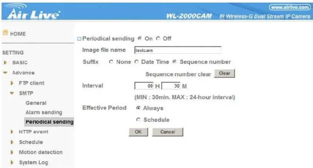
Image file name : Type the file name of the image sent by SMTP up to 10 alphanumeric characters, - (hyphen) and _ (under score).
Suffix : Select a suffix to be added to the file name sent by SMTP.
None : The name of the sent file will be the Image file name.
Date & time : The date & time suffix is added to the Image file name. The date & time suffix consists of lower two-digits of year (2 digits), month (2 digits), date (2 digits), hour (2 digits), minute (2 digits) and second (2 digits), and consecutive number (2 digits), thus 14-digit number is added to the file name.
Sequence number : A consecutive number is added to the Image file name.
Sequence number clear : Click Clear and the suffix of the sequence number returns to 1.
Interval : Set the periodical sending is effective interval. Min value is 30 min and Max value is 24 hours.
Effective period : Set the period when the periodical sending is effective.
Always : The periodical sending is always effective.
Schedule : You can specify the period when the periodical sending is effective in the schedule setting in the other section. Click Schedule and the setting menu for the effective period is displayed.
6-2-3 HTTP Event
Use this menu to set up for capturing and sending images to an HTTP server. By using HTTP client function, you can send the image and audio file which has been shot and recorded linked with the external sensor input or with the built-in motion detection function to HTTP server. HTTP client setting menu is composed of two tabs, General and Alarm sending.
6-2-3-1 General
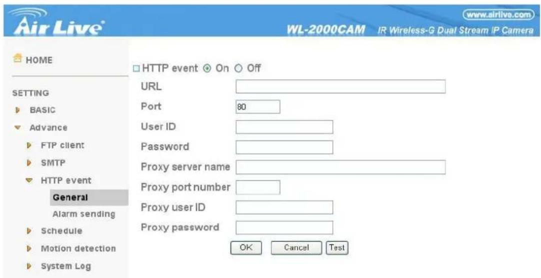
HTTP event: Set up the HTTP server URL, port, user ID, password, and proxy server settings.
6-2-3-2 Alarm Sending
Set to send the mail with connection to the alarm detection by the external sensor input or by the built-in motion detection function.
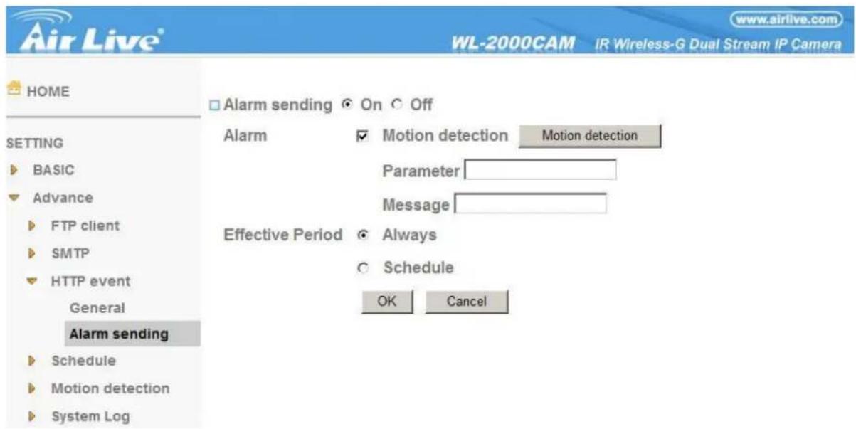
Alarm sending : Select On to set to send mail with connection to the alarm detection.
Motion Detection : Click it on for using Motion Detection function as a sensor. You can set the motion detection function page.
Note :
- Motion Detection works only when the Video mode is set to MPEG4 and the Cropping is set to Off. Alarm Buffer : Select Use alarm buffer when you forward the image/ audio of before and after the alarm detection (pre-alarm, post-alarm). If you do not select it, only the image of the moment of the alarm detection is forwarded. Click Alarm buffer to display the Alarm buffer setting menu. For details, see “Setting the Alarm Buffer — Alarm buffer setting Menu on page.
Effective period : Set the period when the periodical sending is effective.
Always : The periodical sending is always effective.
Schedule : You can specify the period when the periodical sending is effective in the schedule setting in the other section. Click Schedule and the setting menu for the effective period is displayed.
6-2-4 Schedule
When you click Schedule on the Advanced mode menu, the Schedule setting menu appears. This is the same menu as the setting menu which is displayed when you click Schedule to set Effective period and Schedule in FTP client setting menu, e-mail (SMTP) setting menu, Alarm out setting menu and so on.
Example: When setting e-mail (SMTP) (the alarm sending) in the Schedule setting menu.
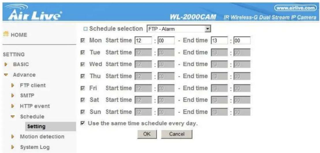
6-2-4-4 Setting
Schedule selection
Select the list box to specify the schedule you want to set. E-mail (SMTP) – Alarm, e-mail (SMTP) – Periodical, FTP – Alarm, FTP – Periodical, HTTP event – Alarm, Alarm output – Alarm or Alarm output – Timer, can be selected.
Mon (Monday) to Sun (Sunday)
The time period on the right of the checked day is the effective period of the schedule.
AirLive WL-2000CAM User's Manual
Start time, End time
Specify the Start time and the End time.
Use the same time schedule every day
When this is checked, the Start time and End time set to Mon (Monday) are applied to all days. In this case, the Start time and End time of the other days than Mon (Monday) cannot be input.
6-2-5 Motion Detection
When you click Motion Detection on the Advance mode menu, the Motion Detection setting menu appears. There are three Motion Detection functions as sensors to set for different detecting zones. Each one has Threshold and Sensitivity inputs which you can adjust to specific zone sequentially. Motion Detection function can support to FTP, SMTP and Alarm output for capturing and sending images or starting alarm output.
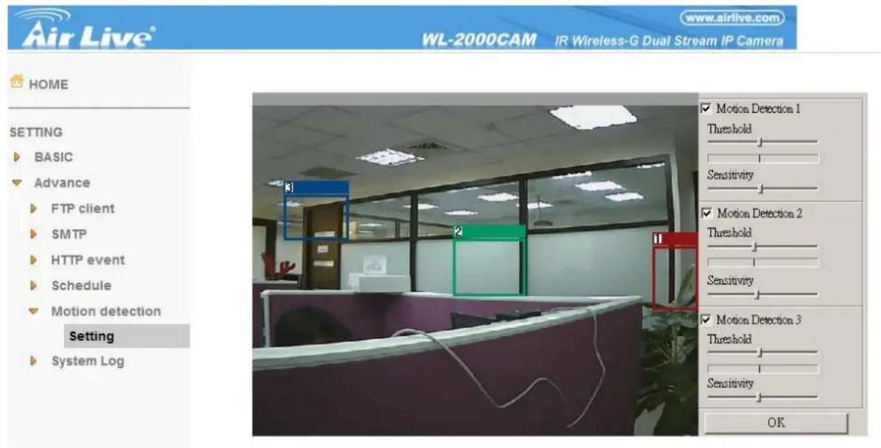
Click it On when you use the Motion Detection function and detecting zone appears for adjusting and moving. The common setting options are displayed below. If you do not wish to use the Motion Detection function, click it Off and press OK.
Motion Detection 1 : Click it on for using Motion Detection 1 function as a sensor. You can adjust and move the detecting zone by using mouse.
Motion Detection 2 : Click it on for using Motion Detection 2 function as a sensor. You can adjust and move the detecting zone by using mouse.
Motion Detection 3 : Click it on for using Motion Detection 3 function as a sensor. You can adjust and move the detecting zone by using mouse.
Threshold : You can use the tool bar to set up-limit value. When detecting zone signals are over setting value, it would carry on assigned work.
Sensitivity : You can use the tool bar to set down-limit value. When detecting zone signals are over setting value, it would carry on assigned work.
AirLive WL-2000CAM User's Manual
Carry out the following steps :
- Click On to Motion Detection 1 choose one of eight orders.
- A detecting zone 1 appears and use mouse to adjust and move the zone boundaries and position.
- Use tool bar to set Threshold and Sensitivity value.
- Follow the steps to set the other Motion Detection.
- Click the OK to save the setting.
Note :
- Be careful! Motion Detection function don't work with Patrol function at same time.
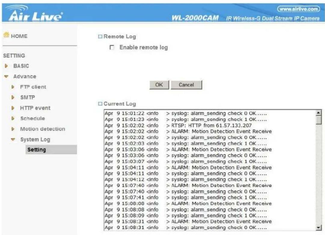
6-2-6 System Log
The System Log function allows users to review any changes and events happened. The system starts logging automatically after started.
Remote Log: Enables user to send the log data to a specified log server.
APPENDIX A – FRAME RATE & BIT RATE TABLE
This chapter provides tables that help you to optimize your IP camera with your network environment. Base on your network upload environment, choose the best Image-Quality setting.
For example, if the network environment is ADSL 256Kb (upload) / 2Mb (download), the most fluent Image-Quality needs to set up under 256 Kb situation.
A.1 MPEG4 @ 30fps / kbps
| Quality | 640*480 | 320*240 | 160*120 |
| Excellent | 1000 | 300 | 90 |
| Detailed | 400 | 150 | 50 |
| Good | 300 | 100 | 30 |
| Standard | 250 | 70 | 25 |
| Medium | 250 | 55 | 20 |
A.2 MPEG4 / kbps, fps
| Image-Size | Bitrate Setting | Frame-Rate Setting | Current Bitrate | Current Frame-Rate |
| 640*480 | 2048 | 30 | 1800 | 26 |
| 640*480 | 2048 | 15 | 2200 | 16 |
| 640*480 | 1536 | 30 | 1500 | 30 |
| 640*480 | 1536 | 15 | 1700 | 16 |
| 640*480 | 1024 | 30 | 1000 | 30 |
| 640*480 | 1024 | 15 | 1000 | 16 |
| 640*480 | 512 | 30 | 500 | 30 |
| 640*480 | 512 | 15 | 600 | 16 |
| 320*240 | 1536 | 30 | 1500 | 30 |
| 320*240 | 1536 | 15 | 1600 | 16 |
| 320*240 | 1024 | 30 | 1000 | 30 |
| 320*240 | 1024 | 15 | 1000 | 16 |
| 320*240 | 512 | 30 | 550 | 30 |
| 320*240 | 512 | 15 | 600 | 16 |
| 160*120 | 1024 | 30 | 950 | 30 |
| 160*120 | 1024 | 15 | 750 | 16 |
| 160*120 | 512 | 30 | 500 | 30 |
| 160*120 | 512 | 15 | 50 | 16 |
| 160*120 | 128 | 30 | 130 | 30 |
| 160*120 | 128 | 15 | 140 | 16 |
A.3 MJPEG @ 15fps / kbps
| Quality | 640*480 | 320*240 | 160*120 |
| Excellent | 4000 | 1500 | 600 |
| Detailed | 2400 | 900 | 400 |
| Good | 1600 | 650 | 300 |
| Standard | 1300 | 500 | 240 |
| Medium | 900 | 350 | 170 |
A.4 MJPEG / kbps, fps
| Image-Size | Quality Setting | Frame-Rate Setting | Current Bitrate | Current Frame-Rate |
| 640*480 | Excellent | 15 | 4000 | 13 |
| 640*480 | Excellent | 5 | 1600 | 5 |
| 640*480 | Good | 15 | 1600 | 13 |
| 640*480 | Good | 5 | 650 | 5 |
| 640*480 | Medium | 15 | 900 | 14 |
| 640*480 | Medium | 5 | 360 | 5 |
| 320*240 | Excellent | 15 | 1500 | 13 |
| 320*240 | Excellent | 5 | 550 | 5 |
| 320*240 | Good | 15 | 650 | 13 |
| 320*240 | Good | 5 | 260 | 5 |
| 320*240 | Medium | 15 | 350 | 13 |
| 160*120 | Medium | 5 | 130 | 5 |
| 160*120 | Excellent | 15 | 600 | 13 |
| 160*120 | Excellent | 5 | 230 | 5 |
| 160*120 | Good | 15 | 300 | 13 |
| 160*120 | Good | 5 | 115 | 5 |
| 160*120 | Medium | 15 | 170 | 13 |
| 160*120 | Medium | 5 | 65 | 5 |
APPENDIX B – STORAGE REQUIREMENT TABLE
This chapter provides tables that help you set your recording storage system.
Please refer to the following table to find out the capability for recording into your hard disk.
B.1 MPEG4 Storage Requirement GB / channel / day @ 30fps
| Quality | 640*480 | 320*240 | 160*120 |
| Excellent | 10.5 | 3.2 | 0.9 |
| Detailed | 4.2 | 1.6 | 0.5 |
| Good | 3.2 | 1.1 | 0.3 |
| Standard | 2.6 | 0.7 | 0.3 |
| Medium | 2.6 | 0.6 | 0.2 |
B.2 MPEG4 Storage Requirement GB / channel / day @ 15fps
| Quality | 640*480 | 320*240 | 160*120 |
| Excellent | 5.3 | 1.6 | 0.4 |
| Detailed | 2.1 | 0.8 | 0.3 |
| Good | 1.6 | 0.6 | 0.2 |
| Standard | 1.3 | 0.4 | 0.1 |
| Medium | 1.3 | 0.3 | 0.1 |
B.3 MPEG4 Storage Requirement GB / channel / day
| Image-Size | Bitrate Setting | Frame-Rate Setting | Current Bitrate |
| 640*480 | 2048 | 30 | 23.0 |
| 640*480 | 2048 | 15 | 22.2 |
| 640*480 | 1536 | 30 | 18.5 |
| 640*480 | 1536 | 15 | 17.9 |
| 640*480 | 1024 | 30 | 10.5 |
| 640*480 | 1024 | 15 | 10.5 |
| 640*480 | 512 | 30 | 5.3 |
| 640*480 | 512 | 15 | 6.3 |
| 320*240 | 1536 | 30 | 15.8 |
| 320*240 | 1536 | 15 | 16.9 |
| 320*240 | 1024 | 30 | 10.5 |
| 320*240 | 1024 | 15 | 10.5 |
| 320*240 | 512 | 30 | 5.8 |
| 320*240 | 512 | 15 | 6.3 |
| 160*120 | 1024 | 30 | 10.0 |
| 160*120 | 1024 | 15 | 7.9 |
| 160*120 | 512 | 30 | 5.3 |
| 160*120 | 512 | 15 | 0.5 |
| 160*120 | 128 | 30 | 1.4 |
| 160*120 | 128 | 15 | 1.5 |

- Declaration of Conformity
- Clause Description
- Before You Use this Product
- Legal Caution
- Heed the safety precautions
- In case of a breakdown
- In case of abnormal operation
- Operation Notice - Operating or storage location
- Ventilation
- Transportation
- Cleaning
- TABLE OF CONTENT
- CHAPTER 1 INSTALLATION ....3
- CHAPTER 2 USING IP CAMERA VIA MOBILE PHONE....5
- CHAPTER 3 USING IP CAMERA VIA WEB BROWSER....6
- CHAPTER 4 SETTING UP WIRELESS CONFIGURATION ....7
- CHAPTER 5 HOW TO USE ....8
- CHAPTER 6 SETTING....11
- APPENDIX A – FRAME RATE & BIT RATE TABLE....38
- APPENDIX B - STORAGE REQUIREMENT TABLE 40
- Chapter 1 Installation
- 1-1 Installation Steps
- 1-2 Package Contents
- 1-3 Overviews
- Bottom:
- Note
- Chapter 2 Using IP Camera via Mobile Phone
- 2-1 3G Mobile Phone Viewing
- Note:
- 2-2 2.5G Mobile Phone Viewing
- Chapter 3 Using IP Camera via Web Browser
- System Requirement
- Chapter 4 Setting up Wireless Configuration
- Chapter 5 How to Use
- 5-1 Accessing the IP Camera
- Note :
- 5-2 Configuration of Main Menu
- 5-2-1 Setting
- Setting
- 5-2-2 Client Setting
- Client setting
- 5-2-3 Image Setup
- 5-2-4 Live View
- Snapshot:
- Audio buttons :
- Video play buttons:
- Chapter 6 Setting
- 6-1 Basic
- 6-1-1 System
- Information
- Day & Time
- Initialize
- 6-1-2 Camera
- 6-1-2-1 General
- Computer View
- RTSP (If RTSP mode is ON)
- RTP (If RTSP mode is ON)
- Unicast streaming:
- Multicast streaming:
- MPEG4 viewer port (If RTSP mode is OFF)
- Quality
- Mobile View
- 6-1-2-3 MJPEG
- MJPEG viewer port
- 6-1-3 Network
- 6-1-3-1 Information
- 6-1-3-2 PPPoE
- 6-1-3-4 UPnP
- 6-1-3-5 IP Notification
- Message
- 6-1-3-6 Wireless
- Status of Wireless Networks
- Wireless Settings
- 6-1-4 Security
- 6-1-4-1 Account
- 6-1-4-2 HTTPS
- 6-2 Advance
- 6-2-1 FTP Client
- 6-2-1-1 General
- 6-2-1-2 Alarm Sending
- 6-2-1-3 Periodical Sending
- 6-2-2 SNMP
- 6-2-2-1 General
- 6-2-2-2 Alarm Sending
- 6-2-2-3 Periodical Sending
- 6-2-3 HTTP Event
- 6-2-3-1 General
- 6-2-3-2 Alarm Sending
- 6-2-4 Schedule
- 6-2-4-4 Setting
- Schedule selection
- Mon (Monday) to Sun (Sunday)
- 6-2-5 Motion Detection
- 6-2-6 System Log
- APPENDIX A – FRAME RATE & BIT RATE TABLE
- APPENDIX B – STORAGE REQUIREMENT TABLE
Brand : AIRLIVE
Model : WL-2000
Category : Security Camera