
FE-201DM - Security Camera AIRLIVE - Free user manual and instructions
Find the device manual for free FE-201DM AIRLIVE in PDF.


| Product Type | Security Camera |
| Brand | AirLive |
| Model | FE-201DM |
| Image Sensor | 1/2.5" Progressive CMOS |
| Maximum Resolution | 1440x1440 (2MP) |
| Lens Type | Fisheye Fix Lens, f=1.25mm, F2.0 |
| Field of View | 180° (Horizontal/Vertical/Diagonal) |
| Min. Illumination | 0.1 Lux (B/W) |
| Day/Night | Removable IR-cut filter |
| Video Compression | H.264, MPEG-4, MJPEG |
| Maximum Frame Rate | 15 fps @ 1440x1440 |
| Display Modes | 360° Panorama, Original, Double Broad, Triple, Quad, ePTZ |
| ePTZ | 10x digital zoom, preset points |
| WDR | WDR Enhanced (100 dB) |
| Audio | Two-way, built-in mic and speaker, external mic/speaker input |
| Alarm I/O | 1x Digital Input, 2x Digital Output |
| On-Board Storage | MicroSD slot (SDHC/SDXC, 64GB+) |
| Network | 10/100 Base-TX Ethernet, PoE (802.3af) |
| Protocols | HTTP, HTTPS, TCP/IP, UDP, SMTP, FTP, DHCP, DDNS, NTP, RTSP, RTP, UPnP, OnVIF (Profile S) |
| Power Supply | DC 12V or PoE (802.3af) |
| Power Consumption | Max 5.3W (PoE) |
| Dimensions | Ø196 x 57.3 mm |
| Weight (Net) | 350 g |
| Operating Temperature | 0° ~ 50°C |
| Certifications | CE, FCC Class B, LVD |
Frequently Asked Questions - FE-201DM AIRLIVE
User questions about FE-201DM AIRLIVE
0 question about this device. Answer the ones you know or ask your own.
Ask a new question about this device
Download the instructions for your Security Camera in PDF format for free! Find your manual FE-201DM - AIRLIVE and take your electronic device back in hand. On this page are published all the documents necessary for the use of your device. FE-201DM by AIRLIVE.
USER MANUAL FE-201DM AIRLIVE
2MP Fisheye Indoor PoE Dome Camera
User's Manual
Air Live®
Powered by OvisLink Corp.
Copyright & Disclaimer
No part of this publication may be reproduced in any form or by any means, whether electronic, mechanical, photocopying, or recording without the written consent of OvisLink Corp.
OvisLink Corp. has made the best effort to ensure the accuracy of the information in this user's guide. However, we are not liable for the inaccuracies or errors in this guide. Please use with caution. All information is subject to change without notice
This product contains some codes from GPL. In compliance with GPL agreement, AirLive will publish the GPL codes on our website. Please go to www.airlive.com and go to the "Support->GPL" menu to download source code.
All Trademarks are properties of their respective holders.
FCC Statement
Federal Communication Commission Interference Statement
This equipment has been tested and found to comply with the limits for a Class B digital device, pursuant to Part 15 of the FCC Rules. These limits are designed to provide reasonable protection against harmful interference in a residential installation. This equipment generates uses and can radiate radio frequency energy and, if not installed and used in accordance with the instructions, may cause harmful interference to radio communications. However, there is no guarantee that interference will not occur in a particular installation. If this equipment does cause harmful interference to radio or television reception, which can be determined by turning the equipment off and on, the A user is encouraged to try to correct the interference by one of the following measures:
■ Reorient or relocate the receiving antenna.
■ Increase the separation between the equipment and receiver.
■ Connect the equipment into an outlet on a circuit different from that to which the receiver is connected.
■ Consult the dealer or an experienced radio/TV technician for help.
FCC Caution
Any changes or modifications not expressly approved by the party responsible for compliance could void the user's authority to operate this equipment. This device complies with Part 15 of the FCC Rules. Operation is subject to the following two conditions: (1) This device may not cause harmful interference, and (2) this device must accept any interference received, including interference that may cause undesired operation. For product available in the USA/Canada market, only channel 1\~11 can be operated.
Selection of other channels is not possible.
This device and its antenna(s) must not be co-located or operation in conjunction with any other antenna or transmitter.
FCC Radiation Exposure Statement
This equipment complies with FCC radiation exposure limits set forth for an uncontrolled environment. This equipment should be installed and operated with minimum distance 20cm between the radiator & your body.
WEEE Marking Warning:
The crossed out wheeled bin indicates the product must not be disposed together with household waste. For the sake of the environment, the product should only be given to entities involved in the reception of waste electronic and electrical equipment. The lists of entities entitled to receive used equipment can be found on the websites of municipalities. Some components of devices such as external wiring, circuit boards and liquid crystal displays have a negative impact on the environment.

Bluetooth®
© 2009 OvisLink Corporation, All Rights Reserved
Table of Contents
1. Overview....1
1.1 Introduction....1
1.2 Features....2
1.3 Product Specification ....2
1.4 System Requirement ....5
2. Package Contents and Installation....6
2.1 Package Content ....6
2.2 Connections....6
2.3 Mounting the camera....9
2.4 Install the Camera in LAN....10
2.5 Connect to IP Camera 11
3. Using IP Camera via Web Browser....14
3.1 Windows Web Browser....14
4. Operating the Network Camera ....15
4.1 Live View....15
4.2 Configuration ....19
5. Configuration ......20
5.1 Network....21
5.2 Video....26
5.3 Audio....35
5.4 Event....37
5.5 Storage ....46
5.6 System....48
6. Operating IP Camera via iOS/Android Device ....55
6.1 Using IP Camera via iOS/Android Device....55
1
Overview
natural_image
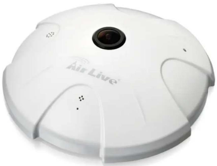
White Air Live sensor device with lens and ventilation slots (no text or symbols visible on body)This user's manual explains how to operate this camera. Users should read this manual completely and carefully in advance.
1.1 Introduction
AirLive FE-201DM is a Fish-Eye Panorama Network Dome Camera featured with 2Mega Pixel resolution respectively and superior H.264-AVC performance and rich functions. FE-201DM includes a fish-eye lens for 360^ panoramic wide angle view without blind spot. It is very suitable to view a wide area with single camera such as hallway, store, and office without the need to install multiple cameras.
The hardware base panorama video processing ability provides user flexible video layout including Panorama, Original View, Double Broad View, Triple View and Quad View. The e-PTZ function, including preset point without moving parts, can replace part of traditional PTZ camera and thus save lost of traditional mechanical Pan/Tilt maintain cost. The PoE function is designed for flexible installation.
Further functions include two-way audio, DI/DO alarm application and micro SD card support for local storage application.
1.2 Features
This manual will illustrate the steps of how to setup and operate this IP camera, so you'll also soon be enjoying the benefits of these product features:
- 15 fps@1440x1440 Full HD
● Dewarping the Image via Fisheye Correction Processor - Removeable IR-cut Filter for Day & Night Function
● Real-time H.264, MPEG-4, and MJPEG Compression
● ROI (Region of Interest) Provide Outstanding e-PTZ function
● Minimum 0.1 Lux for Night Vision
● WDR Enhancement for Visibility in Extremely Bright or Dark Environments
● Two-way Audio Communication, built-in Microphone and Audio Output
● Built-in MicroSD Card Slot, support SDHC/SDXC 64GB or above
● Built-in 802.3af Compliant PoE - OnVIF Compliant for Interoperability
1.3 Product Specification
| Camera FE-201 | DM |
| CPU | Multimedia Soc (System-on-Chip) |
| NOR Flash | 16MB |
| RAM | 512MB |
| Camera Features | |
| Image Sensor | 1/2.5” Progressive CMOS Sensor |
| Maximum Resolution | 1440x1440 |
| Lens Type | Fisheye Fix Lens |
| Focal Length | f=1.25mm |
| Aperture | F=2.0 |
| Field of View | 180°(Horizontal/Vertical/Diagonal) |
| WDR Technology | WDR Enhanced |
| Day/Night | Removable IR-cut filter for day & night function |
| Minimum Illumination | 1.9Lux @F2.0(Color) ; 0.1Lux@F2.0(B/W) |
| Pan/Tilt/Zoom | ePTZ:10x digital zoom |
| On-board Storage | Built-in MicroSD card slot, support SDHC/SDXC 64GB or above |
| Video | |
| Compression | H.264, MJPEG & MPEG-4 |
| Display Mode | 360° Source View, 360° Broad View,180° Double Broad View, Triple View, Quad View,3 PTZ with Source View |
| Maximum Frame Rate | 15fps@1440x144015fps@1600x120015fps@1280x102415fps@800x60015fps@640x480 |
| Maximum Streams | 3 simultaneous streams at Normal Mode |
| S/N Ratio | Above 39 dB |
| Dynamic Range | 100 dB |
| Video Streaming | Adjustable resolution, quality and bitrateROI(Region of Interest) Provide Outstanding e-PTZ function |
| Image Settings | Adjustable image size, quality and bitrateConfigurable brightness, saturation, exposure control, sharpness, contrast, white balance, auto shutter control, auto gain control, noise reduction, EV luminance control, flip & mirror, privacy masks, time stamp, text overlay |
| Audio | |
| Audio Capability | Audio input/output (full duplex) |
| Compression | G.711u |
| Interface | Built-in microphoneExternal microphone input |
| Effective Range | 5 meters |
| Network | |
| Users | Live view for up to 10 clients |
| Protocols | HTTP, HTTPS, TCP/IP, IPv4, UDP, SMTP, FTP, DHCP, DDNS, NTP, DNS, ARP, RTSP, RTP, UPnP, OnVIF(Profile S), Multicast |
| Interface | 10 Base-T/100 Base TX Ethernet(RJ-45) |
| OnVIF | Ver.2.2 |
| Intelligent Video | |
| Motion Detection | Ten-window video motion detection |
| Alarm and Event | |
| Alarm Triggers | Video motion detection, manual trigger, digital input, periodical trigger, system boot, recording notification |
| Alarm Events | Event notification using digital output, HTTP, SMTP, FTP and NAS serverFile upload via HTTP, SMTP, FTP and NAS server |
| General | |
| Connectors | RJ-45 cable connector for Network/PoE connectionAudio inputAudio outputDC 12 V power inputDigital input*1Digital output*2 |
| Power Input | DC 12VIEEE 802.3af PoE |
| Power Consumption | Max. 5.1W(DC 12V)Max. 5.3w(PoE) |
| Dimensions | ∅: 196 x 57.3mm |
| Weight | Net: 350g |
| Safety Certifications | CE, FCC Class B, LVD |
| Operating Temperature | 0°~50°C |
| Operating Humidity | 10%~80% |
| System Requirements | |
| Operating System | Windows® 2000, XP, Vista, 7 |
| Web Browser | Mozilla Firefox 7~10, Internet Explorer 7.x or 8.x, Chrome/Safari 4.0 or above |
| Video Player | VLC, Quick Time, Real Player, Core Player |
1.4 System Requirement
For normal operation and viewing of the network camera, it's recommended that your system meets these minimum requirements for proper operation:
| Item | Requirements |
| CPU Intel Core 2 | Duo E8600(3.33GHz) or higher |
| VGA Monitor Resolution | 1280 x 1024 or higher |
| RAM Minimum 2 GB of RAM | |
| Operating System Window XP, Vista, 7, 8 | |
| Web Browser Internet Explorer 9 or later; Apple Safari; Firefox; Google Chrome | |
| Recorded File Playback | Microsoft Media Player 11.0 or later |
Note: Please keep updating the latest Windows software and service package. (Ex: Net Framework, Windows Media Player, Enhance ActiveX Security)
2
Package Contents and Installation
2.1 Package Content
User can find the following items in the package as below:
- FE-201DM is the main element of the product.
- Power Adapter dedicates 12V DC electric power output to Network Camera.
- Bundle CD provides installation software, application program, important information and instructions for operating the Network Camera.
- Quick Start Guide provides important information and instructions for installing this device.
2.2 Connections
Power Source Requirement
This camera can work with 802.3af PoE switches. However, if you don't have the PoE switch, you can use a power adapter to provide power to camera.
Connectors
Please refer to the diagrams below for the definition of each connector.
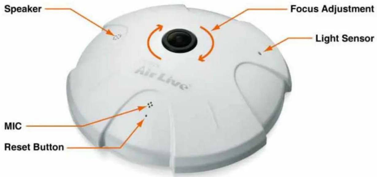
-
Light Sensor: The Light sensor is for detecting IP Camera environmental illumination, and if IP Camera was in the dark/night environment, IR Cut Filter is switched off to let infrared light pass through for clear night view.
-
MIC: The IP Camera has built-in an internal microphone, which is hidden in the pinhole located on the front panel.
-
Lens Focus Adjustment: Rotate the lens to adjust the focal length to the best image. If necessary, clean the lens with a soft cotton cloth.
-
Speaker: The IP Camera has built-in an internal speaker, which is hidden in the pinhole located on the front panel.
-
Reset button: This button is hidden in the pinhole. Insert a pin into the reset hole to press the reset button and keep pressed about 3 seconds until PWR LED start refreshing with orange color.
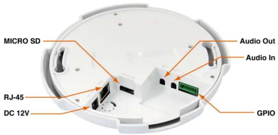
-
Power Jack: The input power is DC 12V. Note: ONLY use power adapter supplied with the package. Otherwise, the product may be damaged.
-
RJ-45 LAN Socket: Connect to PC or Hub / Switch.
For connect to 10Base-T Ethernet or 100Base-TX Fast Ethernet Cabling. This Ethernet port built audio-negotiation protocol which can detect or negotiate the transmission speed of the network automatically.
Please use CAT-5 or above cable to connect the Network Camera to a 100Mbps Fast Ethernet network switch or hub.
Note: ONLY use one power source, either from DC or from 802.3af Power over Ethernet.
- MicroSD Card slot: The IP Camera has built-in a MicroSD card slot which can accepts MicroSD memory card for image / video event recording.
- Audio In: Connect a microphone to the IP Camera, be noted to use actively microphone (normally with power supplier on microphone) for this application.
- Audio Out: Connect a loud speaker to the IP Camera. This is for voice alerting and two-way audio. Be noted to use actively speaker (normally with power supplier on speaker) for this application.
- GPIO: The 7 pin terminal block includes 1 input port and 2 output ports.
| Pin Function Description | ||
| 1 | GND | Digital Input: only one set is designed in this Camera Model. The internal device is also photo-coupled electrical relay; and the external device can be simply an On/Off switch. Each set of On/Off switch can be connected as one trigger source.Digital Output: each digital output pin to COM is a photo-coupled relay on Normal Open status. External device can directly connect to the terminals. However the current that will go through the 2 nodes must not exceed 130mA. An external “Relay” can also be connected to the terminals as an implementation. In this case, current (or/and voltage) limitation is specified by the external Relay. |
| 2 | DI | |
| 3 | GND | |
| 4 | DO_COM | |
| 5 | DO_NO2 | |
| 6 | DO_COM | |
| 7 | DO_NO1 | |
2.3 Mounting the camera
Please attach the supplied alignment sticker to the place you would like to set up first. And then follow the drilling and installing instructions on the sticker to complete Camera's installation.
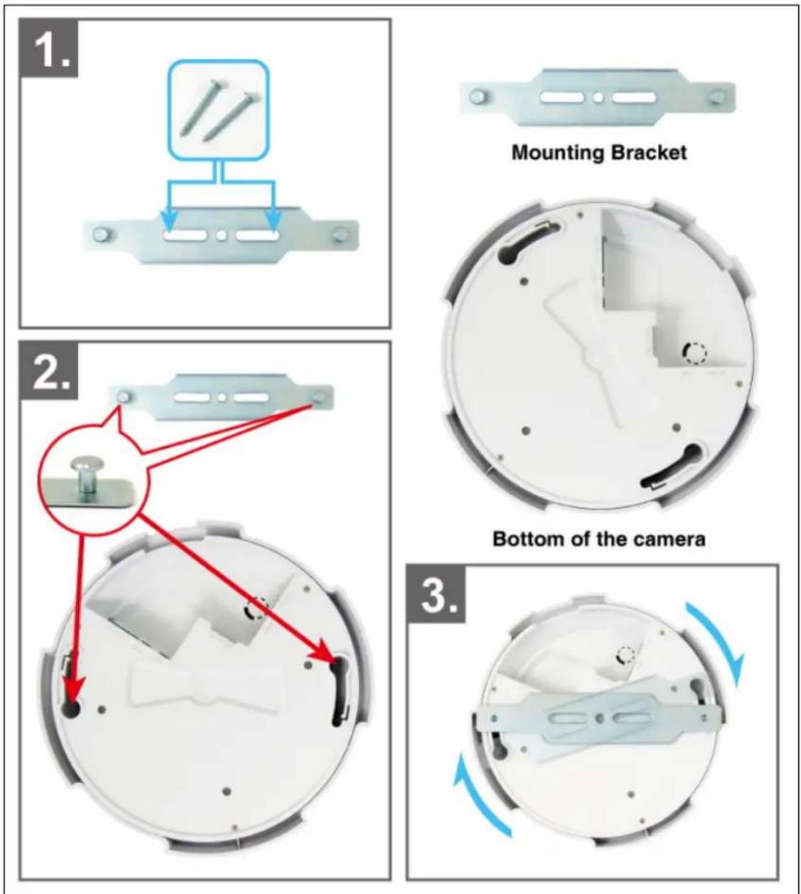
Note: Always mount the Camera on mounting bracket to prevent over heating.
2.4 Install the Camera in LAN
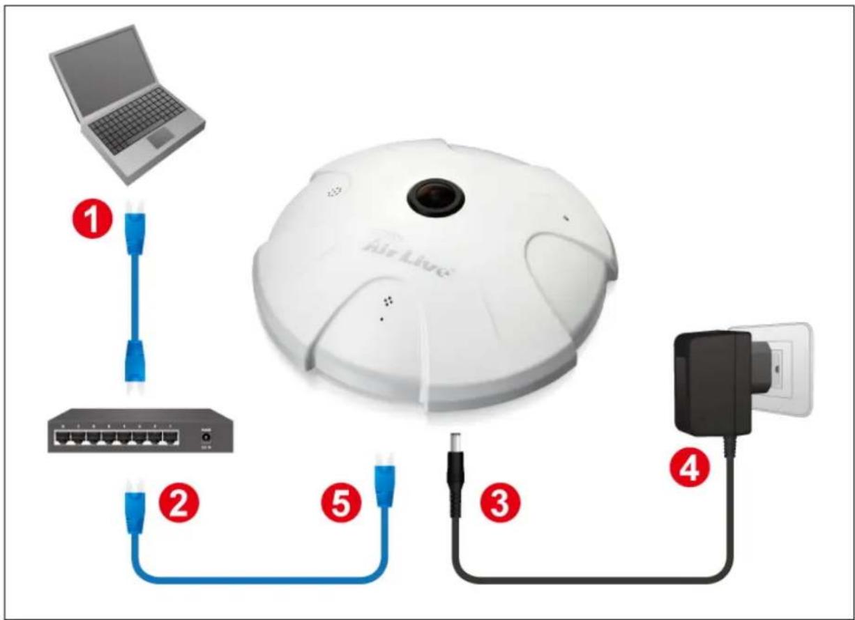
- Prepare a PC/notebook/ultrabook with Ethernet link to the network.
- When PC/notebook is used, connect the LAN port of the device to the network router with an RJ45 network cable (① ②).
- Plug the DC power jack of the power adaptor (③ ④) to Camera and connect the power adaptor to power outlet (110V or 220V).
- Connect the network router to the LAN port of Camera with an RJ45 network cable (⑤).
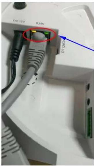
- With power switched on, check the status of the two LEDs at the back of camera: If the Network LED flashes with green color, it confirms that the Camera has successfully linked with the Internet.
natural_image
Close-up of a white electronic device with attached cables and connectors, no visible text or symbolsNetwork LED should blink with green color to indicate successful link to the Internet.
Besides, if Orange LED indicator also light-up at the same time, it means your camera just connect to Intranet only; not through Internet Network.
2.5 Connect to IP Camera
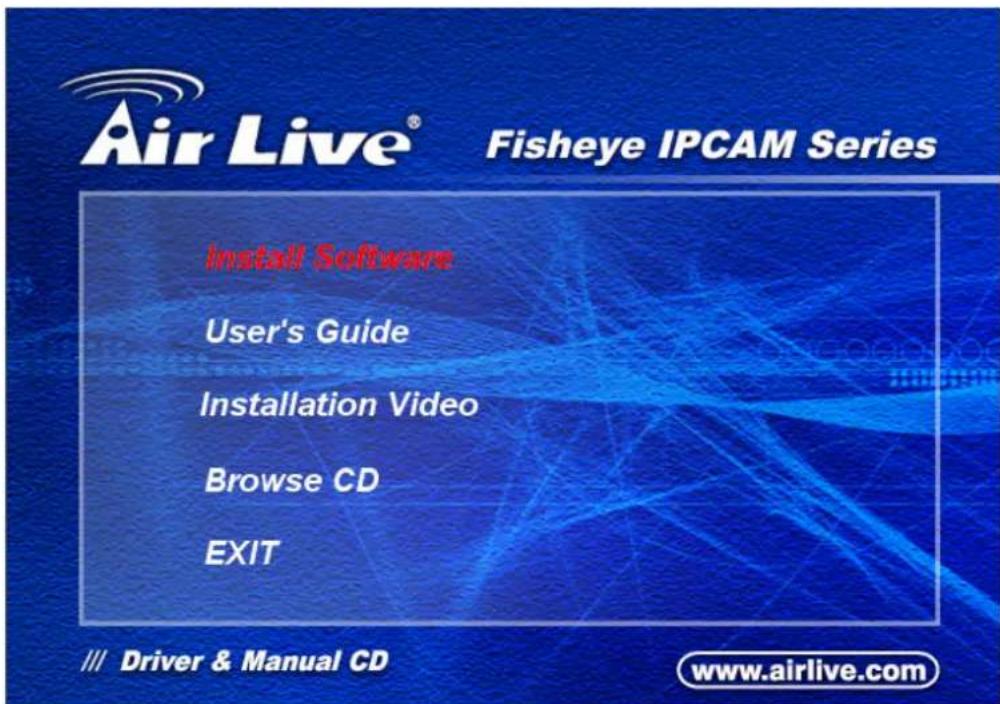
- Insert the bundled CD into your PC/Laptop.
- Auto Run screen pops up, click "Install Software → AirLive IP Wizard II" to install the configuration tool.
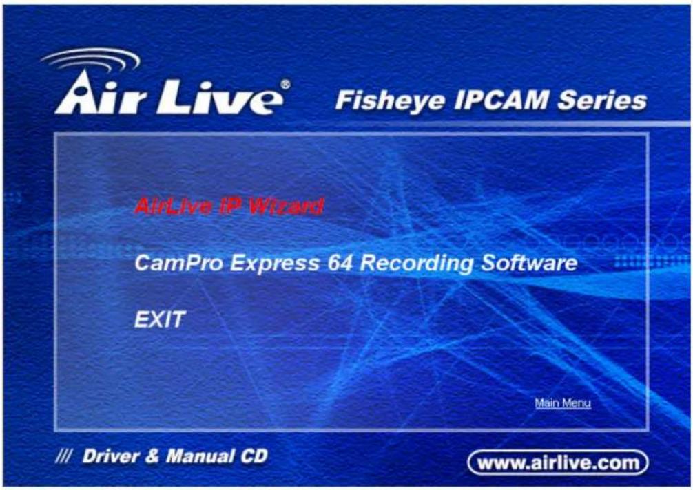
- After completing installation, run the "Air Live IP Wizard II" to start to search the IP camera.
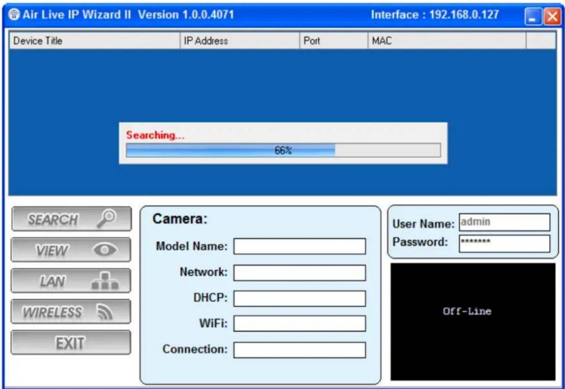
- The entire detected IP camera will be listed out.
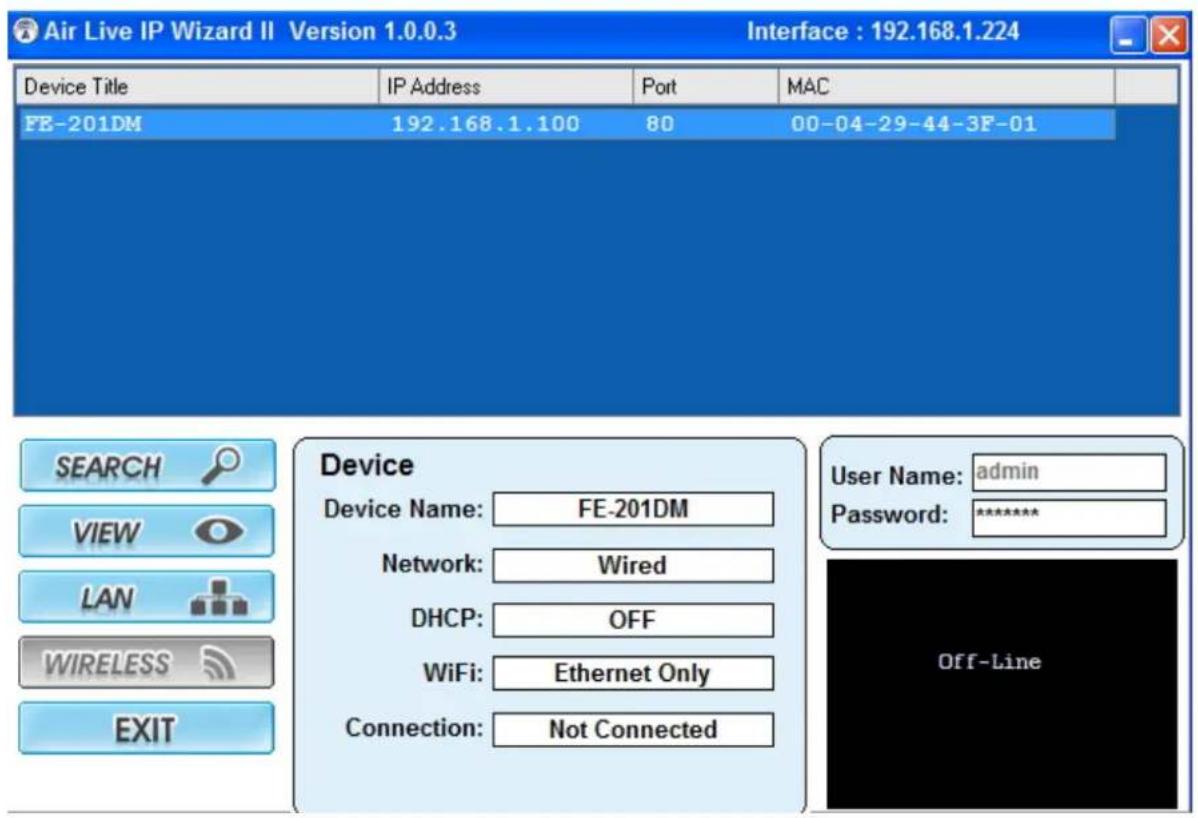
- If the Camera's IP address is in the same IP segment as your LAN, select the founded IP Camera and double click on the item. Then, the default browser will show up and connect to the IP camera's Web automatically.
3
Using IP Camera via Web Browser
3.1 Windows Web Browser
- Open your web browser and enter the IP address or host name of the IP camera in the Location / Address field of your browser.
- Use the default account "admin" and default password "airlive".
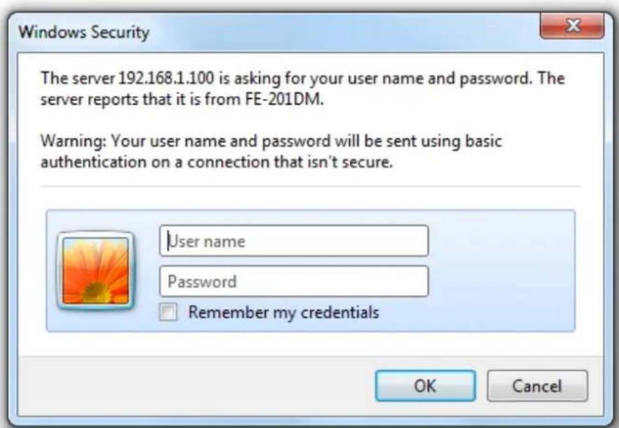
Note: The default user name "admin" and the password "airlive" are the default values. You can change them in the Security Menu. (Please check "Configuration → Security")
- The monitor image will be displayed in your browser. In the left side of main window, you can configure the settings you want. For more details, please refer to the following chapters.
4
Operating the Network Camera
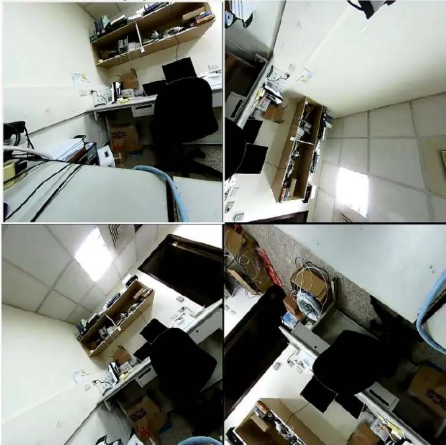
You can operate live view function on the main page, please refer to the description below:
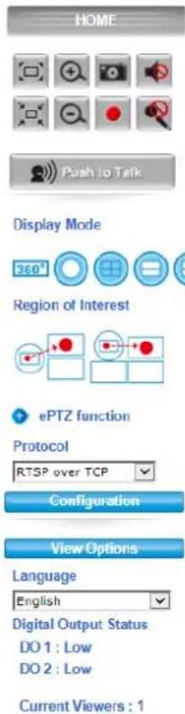
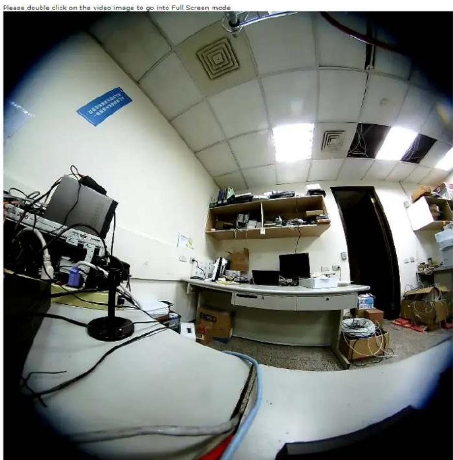
Please double click on the video image to go into Full Screen mode.
natural_image
Four-panel photo collage showing an open kitchen interior with cluttered furniture and equipment, no visible text or symbols.Video Type:H264 Resolution:1920x1920 Bitrate:5861 *Click on video screen to start PT.
4.1 Live View
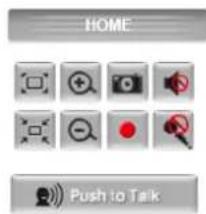
1. Original size

/ Preview Size

Switches live image view between original size (Depends on main stream setting) and preview size.
2. Digital Zoom
You can see larger objects in video.
Note: The digital zoom uses computer algorithm to enlarge the video and may lose some details.

3. Snapshot
Take a snapshot and save images into your computer.
4. Record
Press Record button to start recording and press Stop to terminate the recording.

/ Microphone

You can enable or disable the speaker/microphone function here.
After enable any of these two function, you can adjust the volume by dragging the bar.
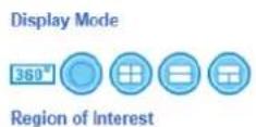
6. Display Mode
| 360° | 360 degree Broad View |
 | 360 degree Full View |
 | Quad View |
 | Double-Broad View(180 degree Ultra Wide Angle View x 2) |
 | Triple View (180 degree Ultra Wide Angle View + Twin PTZ View) |
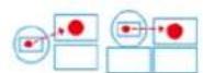
7. Region of Interest
Two Operation Modes (Triple and Quad with Source View) are supported.
Region of Interest
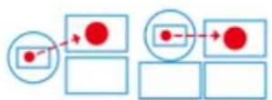
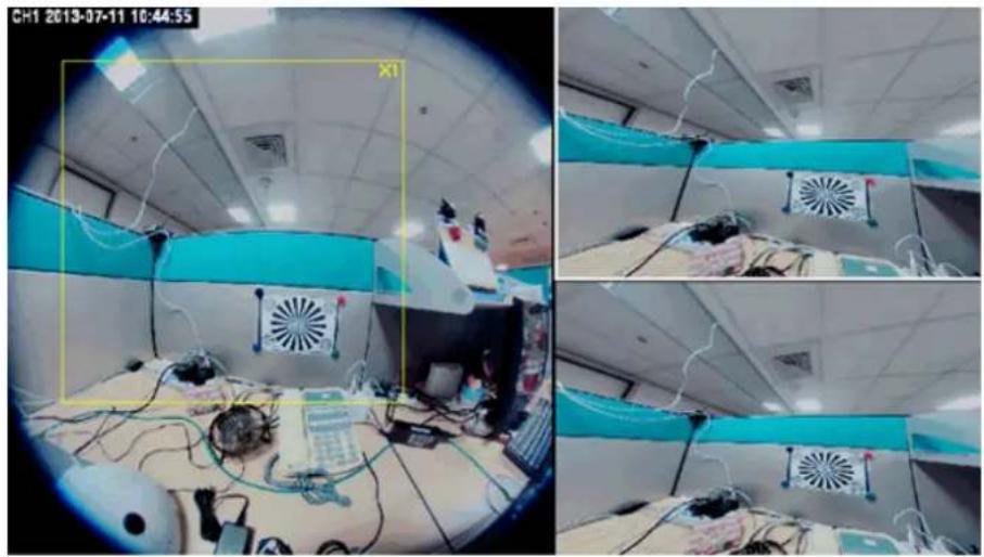
For the first time use, you may Left-click the mouse button under lower-left, upper-right or lower-right Live View Window. Then you could see a x1 frame displaying in the Source View Window.
natural_image
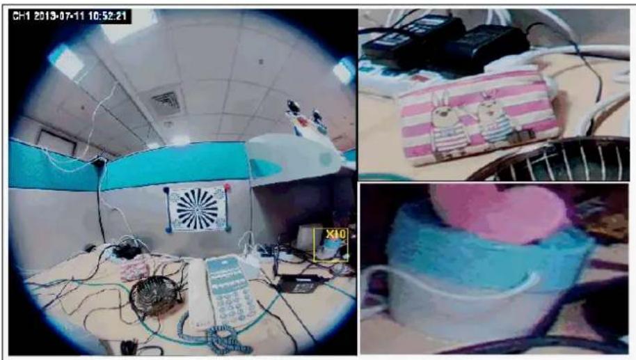
Interior view of a medical or lab setting with equipment and a person in bed, captured through a circular frame (no visible text or symbols)Scrolling the mouse wheel could change region's magnifying power (x1 to x10); and dragging the frame with mouse could move the amplified region.
In the meanwhile, you could also see region's amplification effect displayed real time in the lower-left, upper-right or lower-right Live View Window.
natural_image
Interior of a medical or laboratory room with medical equipment and a pink plush toy, no visible text or symbols8. ePTZ function
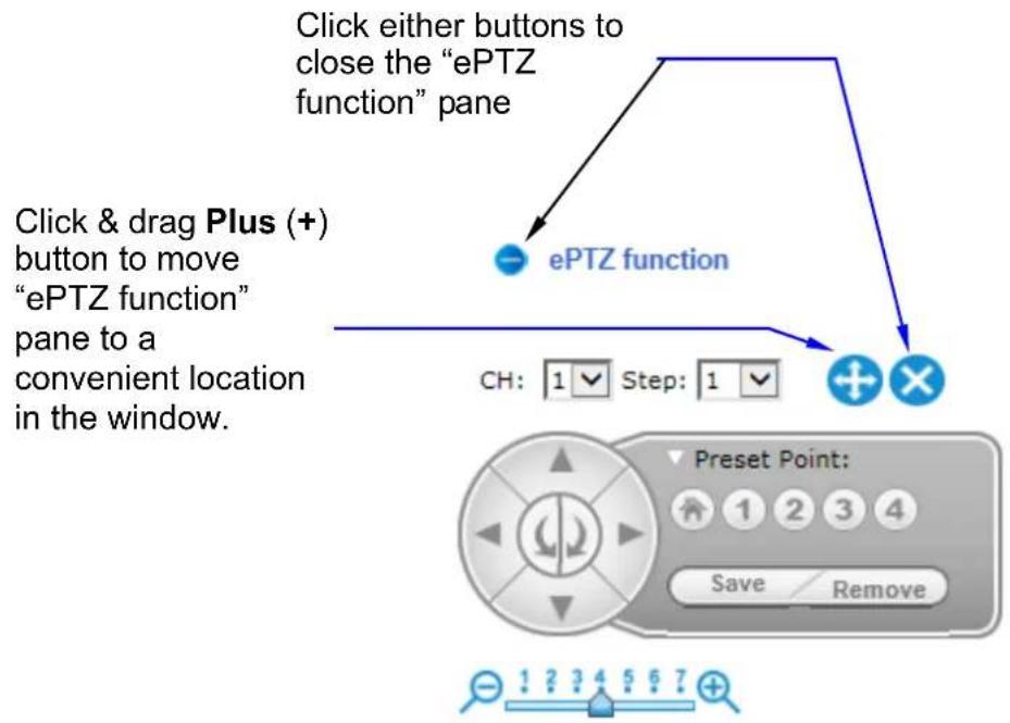
When the Double-Broad View, Triple View or Quad View PTZ display mode is selected, click the “ePTZ function” tool to display the PTZ setting tools as shown and explained below.
flowchart
graph TD
    A["Click either buttons to close the "ePTZ function" pane"] --> B["ePTZ function"]
    B --> C["Step 1 Step 2"]
    C --> D["Preset Point: 1 2 3 4 Save Remove"]
    D --> E["Ch: 1 Step: 1"]
- CH: Select the PTZ channel or display window (1, 2, 3 or 4) to implement PTZ setting.
- Step: Adjust and set the speed of live view panning motion.
- Zoom Slider: Drag slider to zoom-in and zoom-out the selected scene. Zoom setting is saved with the selected pre-defined point of view area.
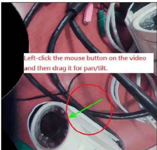
- Directional Buttons: Use to manually pan or rotate the scene to select and zoom a specific area (1 of 4 maximum) to be monitored. To reset the scene back to its original status, click the Home button. You can also directly click the mouse button on the video to drag for pan and tilt, roll the mouse wheel for zoom a selected area.
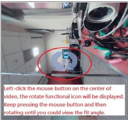
- Preset Point: After panning and zooming, assign the selected area a Preset Point (1 to 4) and click "Save" button to store the setting. The pre-defined point of view areas will be monitored in sequence. To cancel the selection, click "Remove" button.
9. Protocol
User can select proper streaming protocol according to network environment.
10.View Options
It is a pull-down list for video streaming.
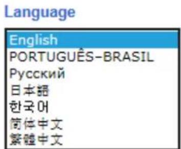
11. Language
FE-201DM supports multi-language.
4.2 Configuration
Click "Configuration" for the camera's detail settings. For more information, please refer to Chapter 5.
5
Configuration
Click the "Configuration" to display sub-menus included:
Network / Video / Audio / Event / Storage / System
Digital Output Status DO 1: Low DO 2: Low
Current Viewers : 1
Video Type:H264 Resolution:1920x1920 Bitrate:5764
5.1 Network
In this menu, you can configure network function here.
1. General

Network
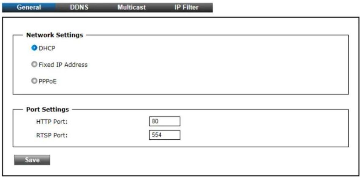
The "General" tabbed pane (shown above) allows you to redefine the network and port protocol settings of the Network Camera.
Network Settings:
- DHCP: This option obtains the available dynamic IP address assigned by the DHCP server each time the Camera is connected to the network.
- Fixed IP Address: This option manually assigns a static IP address to the Network Camera. The default setting is 192.168.1.100.
- PPPoE: Select this option to set PPPoE account & password.

PPPoE
PPPoE User Name:
PPPoE Password:
Recipient E-mail Address:
rcpt@mail.com
(ex: rcpt@mail.com)
SMTP E-mail Server:
192.168.1.1
(ex: mail.examples.com or 192.168.1.1)
SMTP Port:
25 (0..65535)
SMTP user name:
guest
SMTP Password:
●●●●●
Sender E-mail Address:
from@mail.com
(ex: from@mail.com)
Use SSL-TLS:
None
While PPPoE protocol is selected, you may have to enter some more information such as the above picture.
While Camera IP is changed dynamically because of PPPoE Network Connection, its new IP Address will be sent to "Sender E-mail Address" through SMTP service. So you won't worry about the difficulty in Camera's Webpage access.
※ As for the settings of SMTP Service, kindly please contact with your E-mail service provider. After you confirm all parameters are correct and working properly, you may enter them into the text area manually.
Port Settings:
- HTTP Port: Re-define the existing HTTP Port number in the text box.
• RTSP Port: Re-define the existing RTSP Port number in the text box.
Save
: After setups are completed, click "Save" button to apply the settings.
2. DDNS

Network
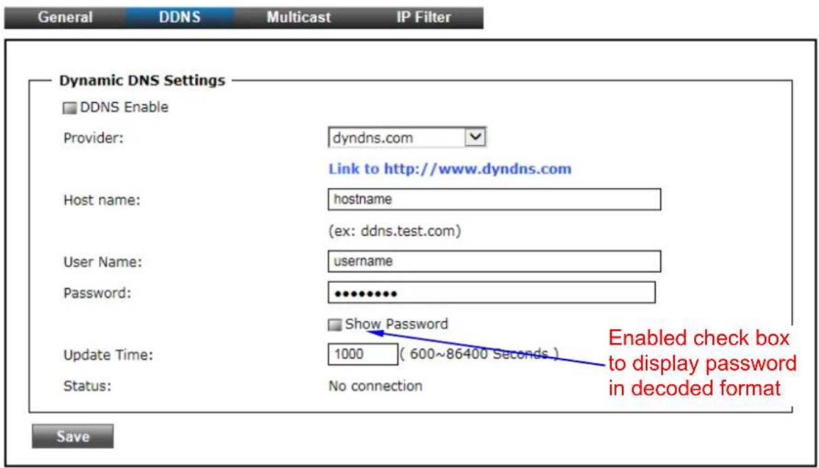
The "DDNS" tabbed pane allows you to configure the Dynamic Domain Name System of your network device with a host name instead of the IP Address.
DDNS Enable: Enable the check box to support DDNS function.
Host Name: Enter the Host name which you registered and got through DNS Service Provider. The assigned host name is used to access the network device instead of IP Address.
User Name/Password: Account authentication for logging into the website of DNS Service Provider.
Update Time: Define a time interval for the device to periodically update and check its access status with website of DNS Service Provider.
Save
: After setups are completed, click "Save" button to apply the settings.
3. Multicast Tab

Network
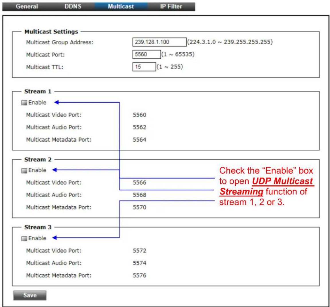
The "Multicast" tabbed pane allows you to open Camera's UDP Multicast Streaming function.
By default, Camera's live stream belongs to RTSP Protocol. It means camera has to send an individual streaming for each client wish to see the videos. So the more the client number is, the larger the network bandwidth required and the bigger loading of the camera.
In other words, the camera can send just one streaming and each client can receive the streaming with Multicast Protocol.
Even with the client number increasing, the network bandwidth is still the same loading with one camera.
: After setups are completed, click "Save" button to apply the settings.
4. IP Filter

Network
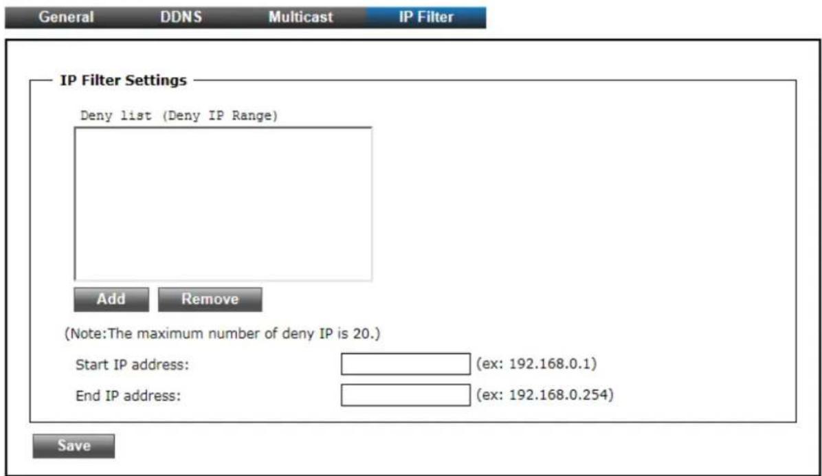
The "IP Filter" tabbed pane could let you configure device IP list which is denied access to this camera.
Add
- Start IP address: Fill in the first address of IP range which you would like to deny its access to camera.
- End IP address: Fill in the last address of IP range which you would like to deny its access to camera.
※ please note that total device numbers listed in the Deny list would be limited to 20.
Save
: Filling the IP range, then click "Save" button to implement the settings.
Remove
: If you would like to re-open the access right of those listed device, select it from the list and then click "Remove" button to apply the settings.
5.2 Video
1. Stream

Video
Stream
Video
Privacy Mask
Video quality settings for stream 1
Connection template:
Mode:
Frame Size:
Maximum Frame Rate:
Streaming Mode:
Bitrate:
Intra frame period:
Text Overlay
Text Field:
Time Stamp
RTSP Port Access Name:
Customized
H264
1440x1440
15 FPS
CBR
6 Mbps
15
CH1
live1.sdp
Video quality settings for stream 2
Connection template:
Mode:
Frame Size:
Maximum Frame Rate:
Streaming Mode:
Bitrate:
Intra frame period:
√ Text Overlay
Text Field:
Time Stamp
RTSP Port Access Name:
Customized
H264
1600x1200
15 FPS
CBR
2 Mbps
15
CH2
live2.sdp
Video quality settings for stream 3
Connection template:
Mode:
Frame Size:
Maximum Frame Rate:
Streaming Mode:
Bitrate:
Intra frame period:
Text Overlay
Text Field:
Time Stamp
RTSP Port Access Name:
Customized
H264
1280x1024
15 FPS
CBR
768 Kbps
15
CH3
live3.sdp
Save
The “Stream” tabbed pane (see above figure) provides the adjustments for the video quality of the Camera streaming function. The pane offers the following three modes of video quality setting:
- Video quality settings for stream 1: This is the primary quality setting for live view streaming.
- Video quality settings for stream 2: This is the secondary quality setting for live view streaming.
- Video quality settings for stream 3(Recording Stream Quality): This setting is geared for Recording Stream saved in the SD Card use.
※ If the “Video Event Alarm Setting by Video” is enabled, an alert message will display requiring you to disable the feature first before proceeding to change the Streaming settings. Otherwise, adjustments to video quality streaming settings cannot be accomplished.
The quality setting items on this pane are as follows:.
- Connection template: Four option modes are available; "Fast," "General," "Low," and "Customized" modes.
- Mode: Three modes of encoding options are offered; "H264," "MJPEG," and "MPEG4."
- Frame Size: 3 types of streamed frame resolutions are available to select; "1440x1440," "1600x1200," and "1280x1024"
• Maximum Frame Rate: Available rate options are; 1, 2, 3, 5, 8, 10 & 15 frames per second (FPS). - Streaming Mode: Two choices of streaming modes are offered; "VBR (variable bit rate)" and "CBR (constant bit rate)."
- Bit Rate: The options for streaming mode quality are expressed differently between VBR and CBR.
- VBR: Standard, High, Highest
- CBR: 64K bps, 128K bps, 184K bps, 200K bps, 256K bps, 384K bps, 512K bps, 768K bps, 1M bps, 1.5M bps, 2M bps, 3M bps, 4M bps, 5M bps and 6M bps
- Intra frame period: Available choices are; 5, 8, 10, 15, 20, 25, 30, 40, 50 & 60 frames per period. This function will let you choose how long distance between two I-Frames.
Lager value means longer distance between two I-Frames and this selection is suitable for the stable Network Bandwidth Environment; so we suggest the smaller value selection is proper to the worse Network Bandwidth Environment.
- Text Overlay: When enabled, each streamed frame will be overlaid with the Camera ID (text field) and stamped with date/time (if enabled) as illustrated below.
√ Text Overlay
Text Field:
CH1
Time Stamp
- RTSP Port Access Name: When RTSP or VLC media-player is used, the port can be renamed with easy to remember pathname.
For example: the default RTSP Port Access Name is live1.sdp ; it means your playback stream name would be "RTSP://camera's IP address/live1.sdp"
Save
: After setups are completed, click "Save" button to apply the settings.
2. Video:
Video
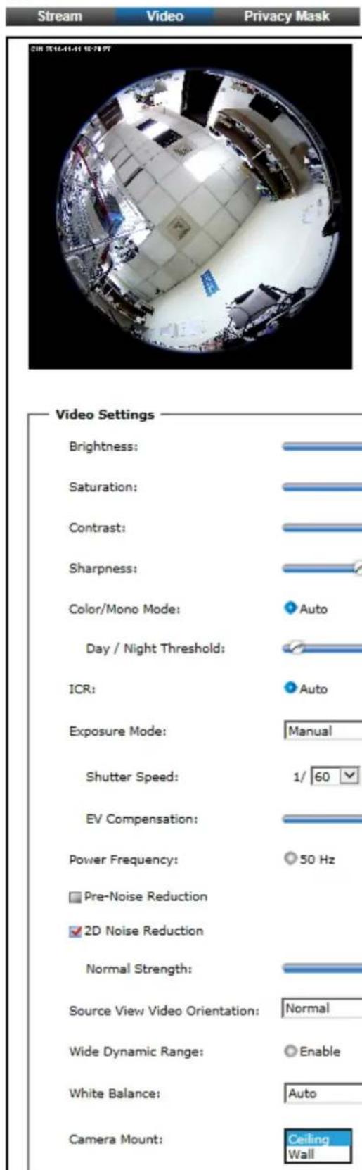
The "Video" tabbed pane lets you to perform live adjustments and improvement of the Camera captured video effect relative to the target environment.
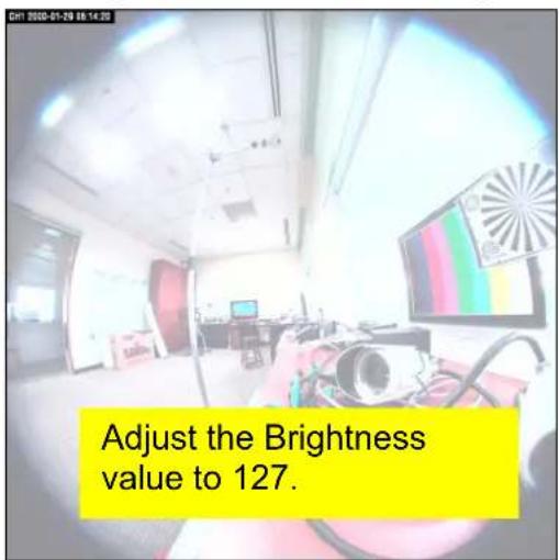
- Brightness: The luminance of the captured image apart from its hue or saturation. Try to assign the fit value according to the environment.
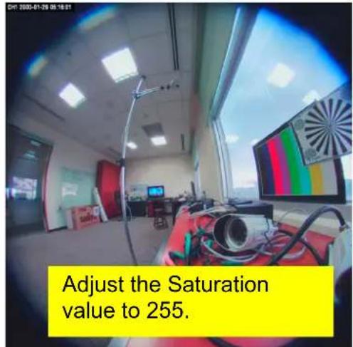
- Saturation: The degree of intensity and purity of a specific color. Try to assign the fit value according to the environment.
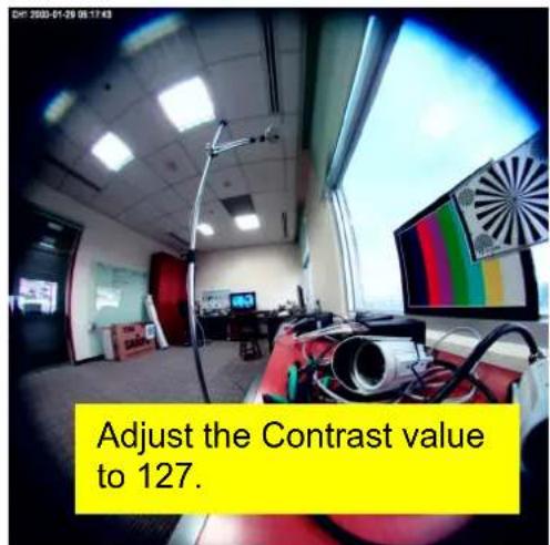
- Contrast: The brightness ratio of the lightest to the darkest part of the video image. Try to assign the fit value according to the environment.
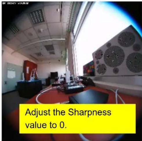
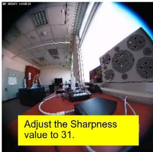
- Sharpness: Sharpness can be defined as edge contrast. So when we increase sharpness, we increase the contrast only along/near edges. Try to assign the fit value according to the environment.
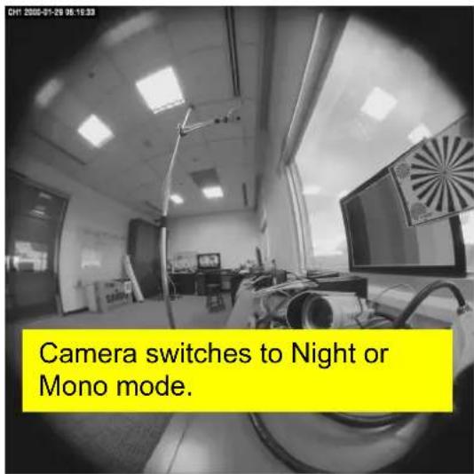
- Day/Night Threshold Set the illumination lux value (5 \~ 100) to auto-trigger the Camera into “day” or “night” mode relative to luminance of the area under surveillance. When the environment luminance becomes higher than the set lux value, the Camera will auto switch to “day” or “color” mode. Otherwise, it will remain at “night” or “mono” mode.
- ICR: Used for the camera to produce true color images, which avoid the color deviation for the capture images effectively.
- Exposure Mode: There are three options (Auto, Manual, and Clear Motion). When you select Manual mode, you can adjust Sutter speed.
- Pre-Noise Reduction & 2D Noise Reduction: Both of them are one kind of technology to provide clearer video with less noise under poor lighting conditions, making it easier to identify people or objects. Try to set them according to the stream quality.
- Wide Dynamic Range: Enable this function could let camera provide clear images even under backlighting.
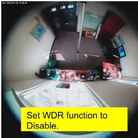
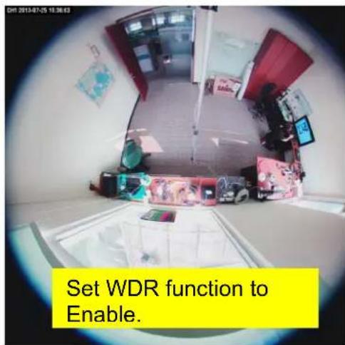
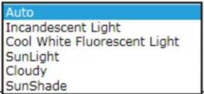
- White Balance: Because camera doesn't have ability to automatically adjust different color (temperature) to the environment, six templates are provided to let you choose for different light.
White Balance:
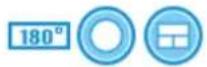
- Camera Mount: Three camera mounting types could be chose and will also bring different kinds of Display Mode.
- Ceiling:
Display Mode

- Wall:
Display Mode
3. Privacy Mask:

Video
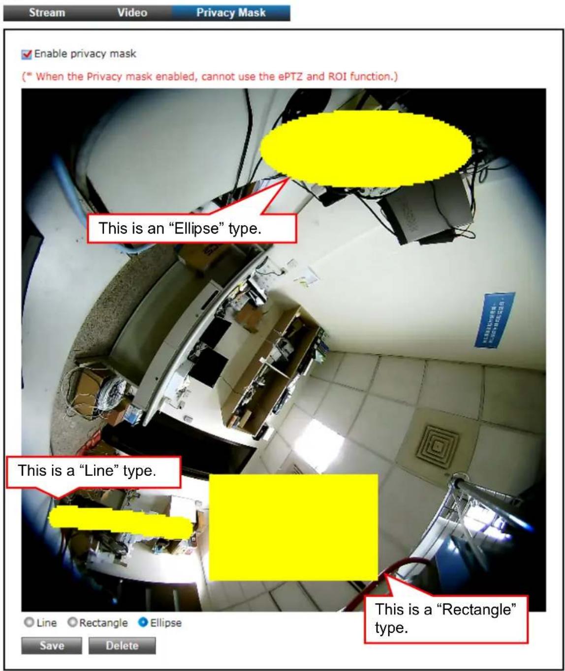
The "Privacy Mask" tabbed pane allows you to mask or block private areas from surveillance for privacy reason.
■ To block a private area from surveillance, follow the procedure below:
1) Initially select the masking shape, e.g., "Line," "Rectangle," or "Ellipse" (see figure above) you wish to use as screen to block the area from surveillance.
2) Click and drag the mouse cursor to lay out a masking screen on the area you wish to block, and then release the mouse right button. Notice that the laid out screen turns into phantom block.
3) If the laid out screen needs correction, click "Delete" button and redo the masking screen lay out process.
4) Once the masking screen is acceptable, click the "Enable Privacy Mask" check box followed by clicking of the "Save" button. This will turn the laid out screen into solid block.
5.3 Audio
1. System
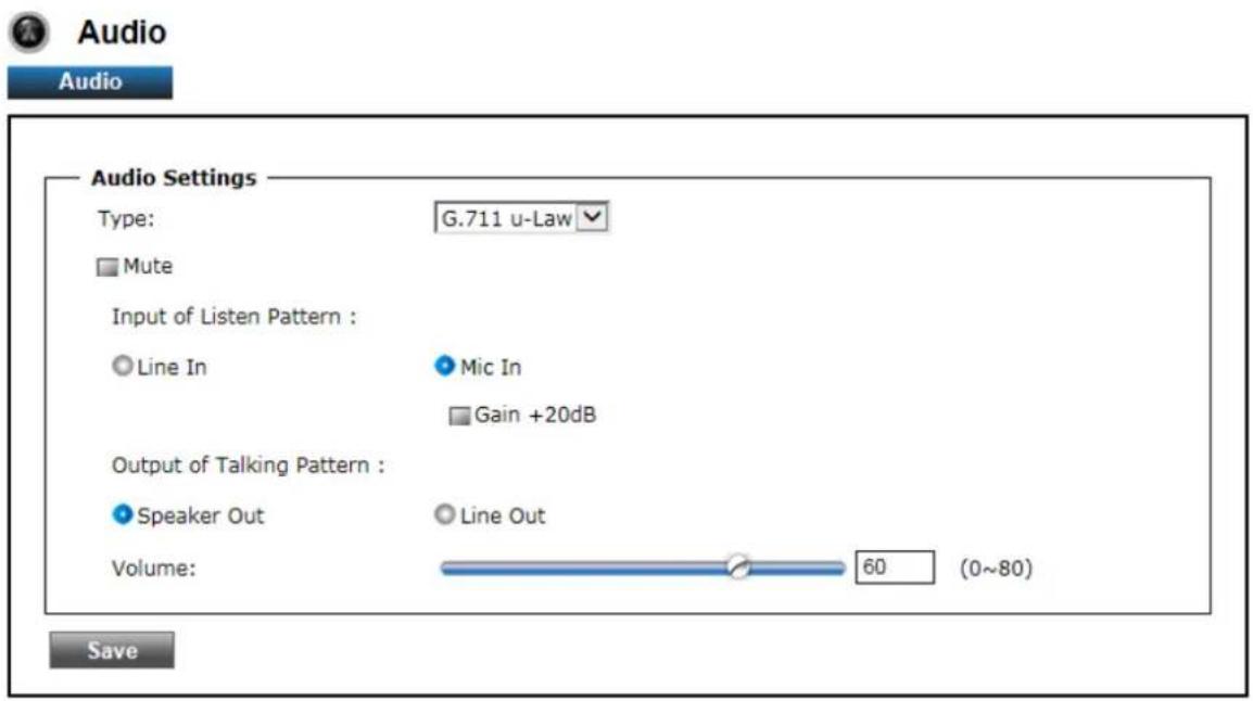
The" Audio" tabbed pane provides the following audio adjustments to your Camera microphone and speaker.
- Mute: Enable or disable mute function of the Camera microphone.
- Input of Listen Pattern: Click to select where audio source comes from.
Line In: Plug an audio source device into the Audio-In port of camera. And its playback volume could be adjusted by moving the slider to the left to decrease; and to the right to increase the volume.
MIC In: Connect a microphone into the Audio-In port of camera, be noted to use actively microphone (normally with power supplier on microphone) for this application. Enable or disable “Gain +20dB” function of the Camera microphone. Enable this function will amplify the signal from the microphone jack.
• Output of Talking Pattern: Click to select where audio sound output to.
Speaker Out: Built-in speaker's volume could be adjusted by moving the slider to the left to decrease; and to the right to increase the volume.
Line Out: Connect a loud speaker to the Audio-Out port of camera. This is for voice alerting and two-way audio. Be noted to use actively speaker (normally with power supplier on speaker) for this application.
Save
: After setups are completed, click "Save" button to apply the settings.
5.4 Event
1. Motion Detection

Event
Motion Detection
Video
Snapshot
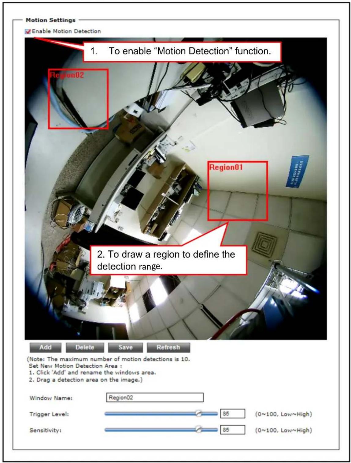
From the "Motion" tabbed pane, you can define specific target areas within the scope of surveillance to focus the motion detection function.
■ Defining multiple motion detection areas:
1) Enable the "Enable Motion Detection" check box.
2) Click "Add" button and a default frame will pop-up on the screen.
3) Click and hold inside the frame to drag it to the location where you want to focus detection. Resize the frame by dragging its corners or borders.
4) To assign unique names to each framed location for easy identification, click on the frame and a "Window Name" text box with the default name of the selected frame, will appear at the bottom of the pane (see figure below). Enter a new name and click the "Save" button. Wait for a while for the change to take effect.
5) To delete a frame that is no longer needed but was previously saved, click on the unwanted frame and click "Delete" button. The frame will disappear after a while.
6) To delete multiple frames that are not yet saved, directly click the "Refresh" button instead of deleting them individually. The "Refresh" button will automatically clears all unsaved frames.
. ※ Total defined motion detection areas cannot exceed 10 frames.
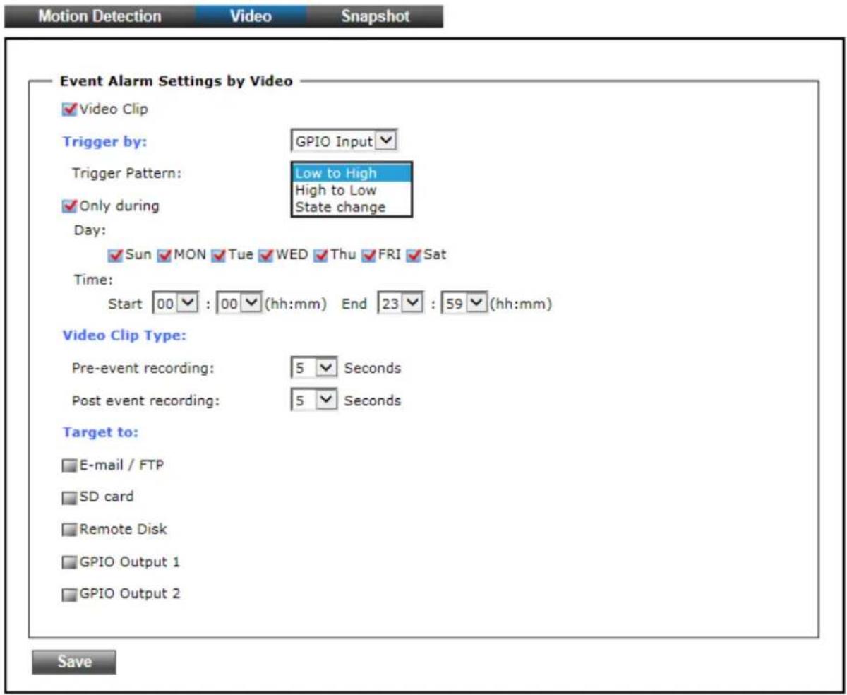
2. Video
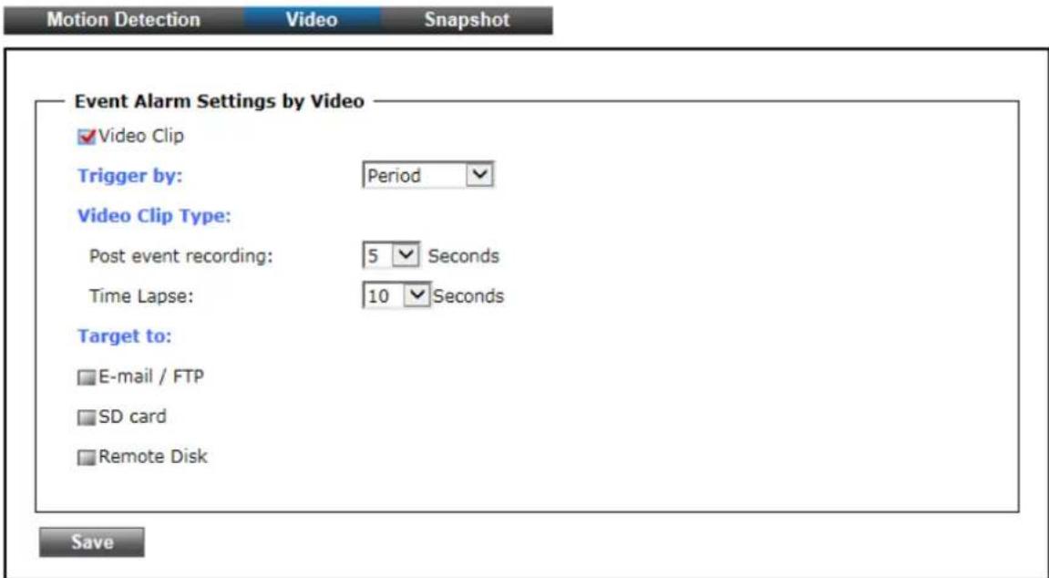
The Video tabbed pane sets the video recording trigger method to use when motion is detected by the Camera. The four methods available for selection are Period, Schedule, Motion, and GPIO Input, each of which can be set up with user scheduled recoding time and duration, as well as defining the video record file target destination.
- Period: This method will trigger the Camera video surveillance/recording operation for a defined Time Lapse (in seconds) whenever motion is detected. The video record may be provided to host by E-mail/FTP, stored in the SD card, Remote Disk as selected or through all of them.

Event
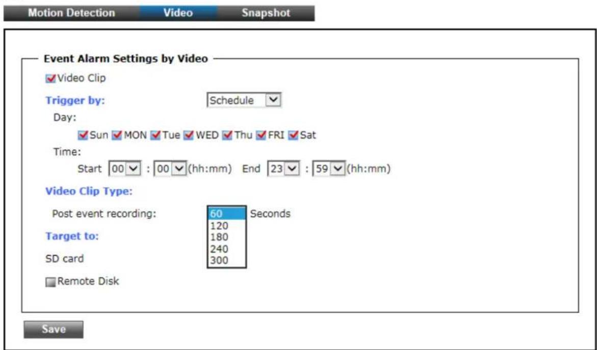
- Schedule: This method activates the Camera video surveillance/recording operation continuously when the defined days of the week and set time of the set days are met. Motion is ignored with this method. Each recording time-span is in accordance with the setting value of Post event recording (in seconds) and the video record is stored in the SD card, Remote Disk as selected or through both of them.

Event
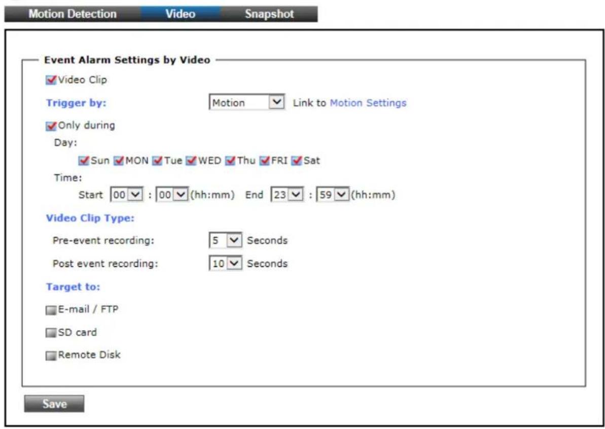
- Motion: This method will trigger the Camera video surveillance/recording operation whenever motion is detected within the defined days of the week and at the time of the set days.
Each recording time-span is in accordance with the total value of Pre-event recording and Post event recording (in seconds). And the video record may be provided to host by E-mail/FTP, stored in the SD card, Remote Disk as selected or through all of them.

Event
- GPIO Input On the defined days of the week and at certain time of the set days, the Camera will trigger its GPIO Input Signal when its state changes. Each recording time-span is in accordance with the total value of Pre-event recording and Post event recording (in seconds). And the video record may be provided to host by E-mail/FTP, stored in the SD card, Remote Disk, activated GPIO Output Port or through all of them.

Event
3. Snapshot
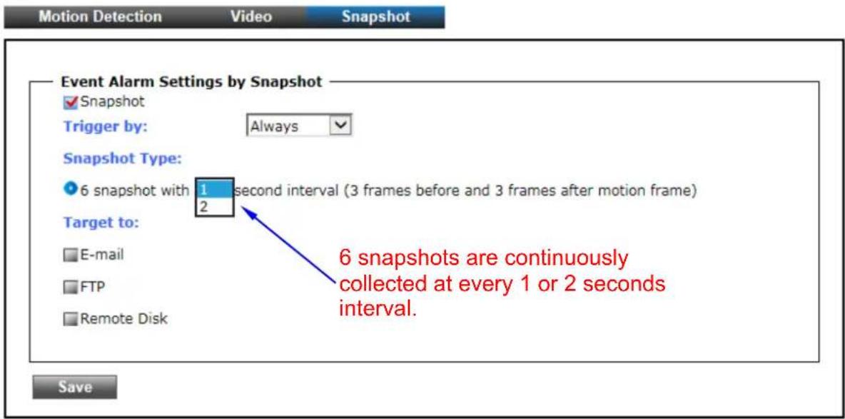
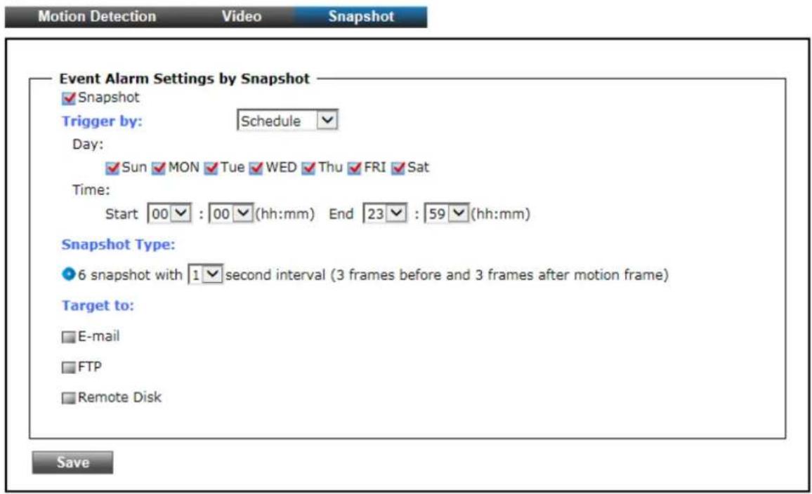
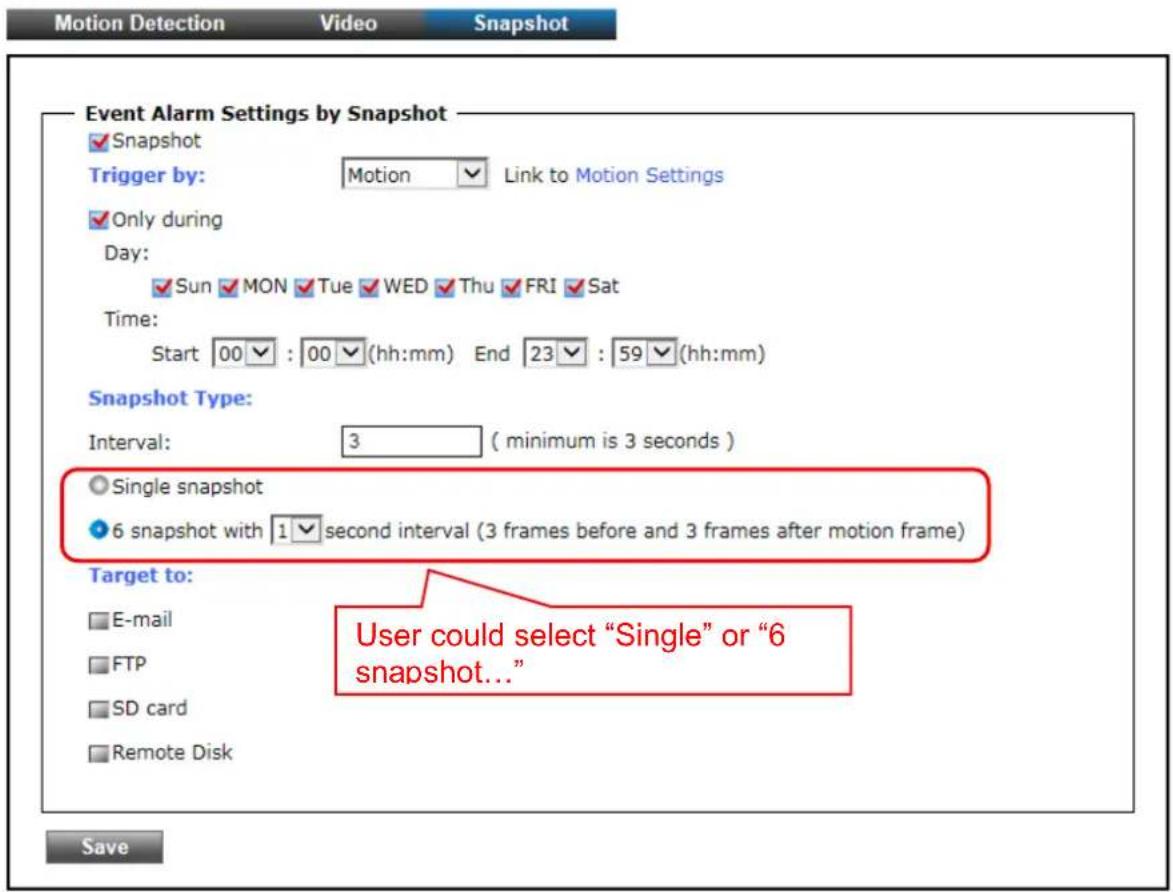
The Snapshot tabbed pane sets the Camera to take snapshot images when motion is detected. The four methods available for selection are Always, Schedule, Motion, and GPIO Input, each of which can be set up with user scheduled recoding time and duration, as well as defining the video record file target destination.
- Always: Under this method, the Camera automatically continuous to capture 6 snapshots of the area under surveillance at every 1 or 2 seconds interval. 3 previous snapshot frames are collected from the Camera buffer and 3 snapshot frames are captured live. The stream of accumulated snapshots may be sent to host by E-mail, FTP, stored in the SD card, Remote Disk as preferred or through all of them.

Event
- Schedule: This method activates the Camera snapshot operation continuously when the defined days of the week and set time of the set days are met. The Camera will continuously capture 6 snapshots of the area under surveillance at every 1 or 2 seconds interval. 3 previous snapshot frames are collected from the Camera buffer and 3 snapshot frames are captured live. The stream of accumulated snapshots may be sent to host by E-mail, FTP, stored in the SD card, Remote Disk as preferred or through all of them.

Event
- Motion: This method will trigger the Camera snapshot operation according to the set time interval (in seconds) whenever motion is detected within the defined days of the week and at the time of the set days. Single or 6 snapshots may be captured as defined. The stream of accumulated snapshots may be sent to host by E-mail, FTP, stored in the SD card, Remote Disk as preferred or through all of them.

Event
- GPIO: On the defined days of the week and at certain time of the set days, the Camera will trigger its GPIO Input Signal according to the set time interval (in seconds) when its state changes. Single or 6 snapshots may be captured at a time as defined.

Event

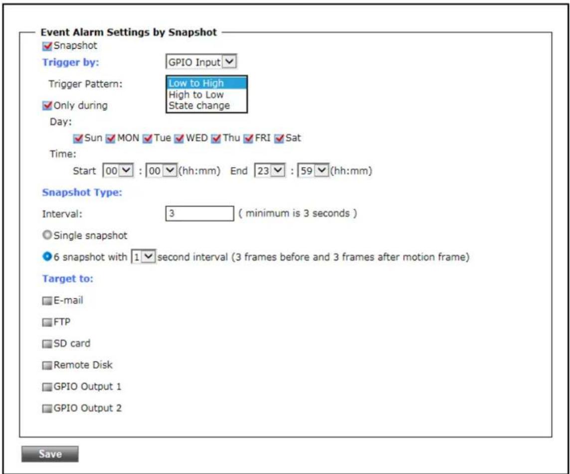
The stream of accumulated snapshots may be sent to host through E-mail, FTP, stored in the SD card, Remote Disk, activated GPIO Output Port; per selection or through all of them. When selected, the setup dialog for these methods will display is illustrated in the following figure.
Target to:
Recipient E-mail Address:
SMTP E-mail Server:
Port:
User Name:
Password:
Sender E-mail Address:
Use SSL-TLS:
Test E-mail
√ FTP
FTP Server:
FTP Server Port:
User Name:
Password:
Path:
Filename Prefix:
Test FTP
SD card
rcpt@mail.com (ex: rcpt@mail.com)
192.168.1.1 (ex: mail.examples.com or 192.168.1.1)
25 (0..65535)
guest
●●●●●
from@mail.com
None SSL-TLS STARTTLS
192.168.1.1 (ex: ftp.domain.com or 192.168.1.1)
21 (0..65535)
guest
●●●●●
\ftp\upload (ex: \ftp\upload )
event (ex: event)
※ As for the settings of SMTP Service, kindly please contact with your E-mail service provider. After you confirm all parameters are correct and working properly, you may enter them into the text area manually.
※ As for the settings of FTP Service, kindly please contact with your FTP service provider. While all parameters filled in Windows FTP Transferring Utility are correct and working properly under your Laptop or other PC, you may enter them into the text area manually.
5.5 Storage
1. Storage
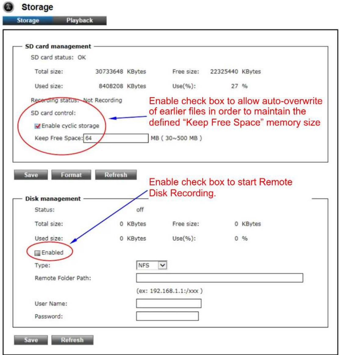
Clicking the "Storage" button will display the following tabbed panes to provide information on existing local storage, such as disk size info, type, and status. If recording is in progress when clicking the "Storage" button, a warning message will occur.
MicroSD card management:
- Save : Click this button to save changes to the SD card control setting.
- Format: Click this button to format the SD memory card
Refresh
- : Click this button to refresh the SD card information.
Disk management:
• Type: NFS and SMBFS two kind of Remote Server are provided.
- Remote Folder Path: If NFS Server type is selected, shared folder path will be filled in like "192.168.1.1:/xxx" syntax; if SMBFS Server type is selected, shared folder path will be filled in like "192.168.1.1/xxx" syntax.
- User Name: Fill in the username for authentication of Remote Server.
- Password: Fill in the password for authentication of Remote Server.
• Save : Click this button to save changes to the setting of Remote Server.
- : Click this button to refresh the server disk's information.
Save
Refresh
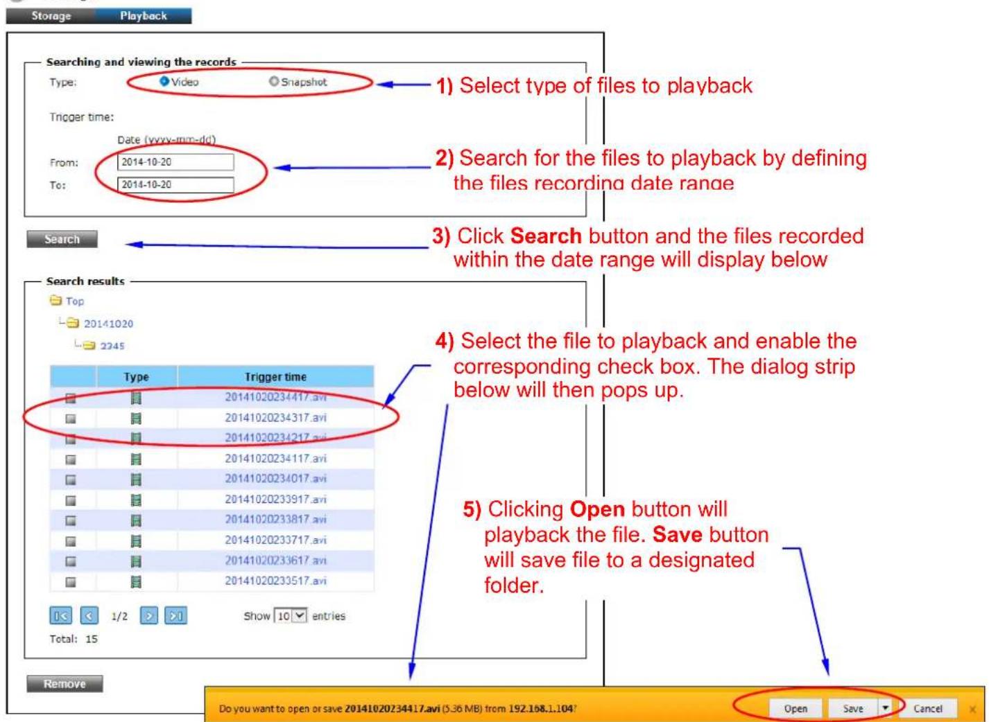
2. Playback:

Storage
5.6 System
1. Information

System
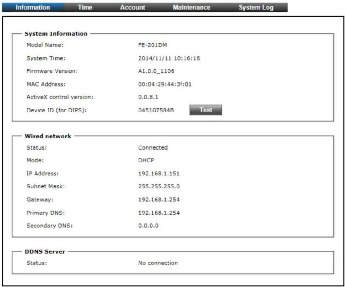
The “Information” tabbed pane provides the existing system status of the Camera which includes Model Name, System Time, Firmware Version, MAC Address, ActiveX Control Version, Wired Network and DDNS Server Status.
2. Time

System
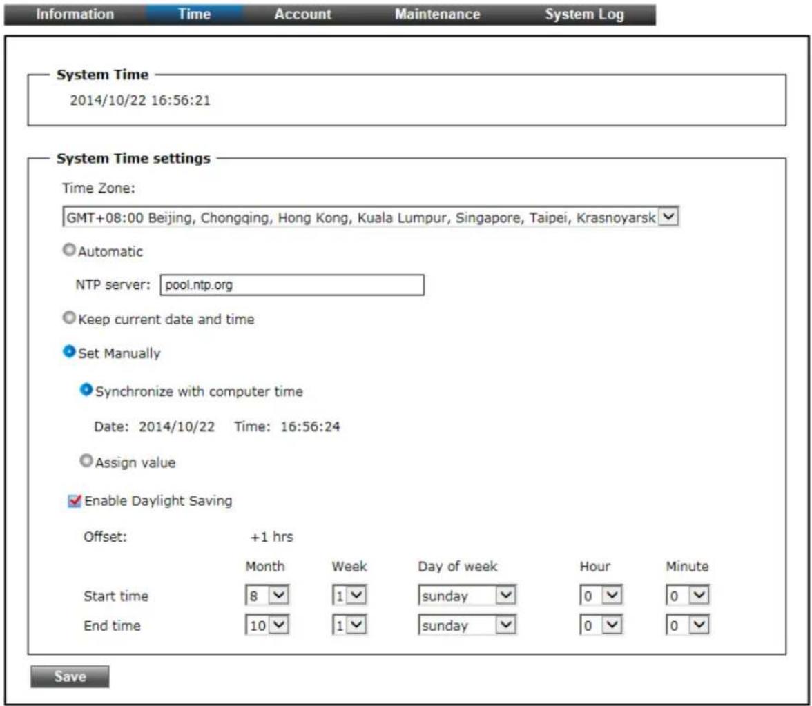
The "Time" tabbed pane is where you set up the clock of your Camera to synchronize with your local time.
- System TimeThe Network Camera current date and time is applied and displayed here based on the setup status of the System Time Settings as detailed below.
- Time Zone: Select the applicable Time Zone of your city in reference to Greenwich Mean Time.
- Automatic: Select this item if you want to automatically synchronize the Camera clock with your manually entered Network Time Protocol (NTP) Server.
-
Keep current date and time setting : Select this option in lieu of automatic synchronization if the Camera is not connected to NTP Server and uses its own embedded clock.
-
Set manually:
Synchronize with the computer Time: Select this option to manually synchronize the Network Camera clock (date and time) with that of the local host computer.
Assign value: Select this option to enter the date and time manually. - Enable Daylight Saving: Select this option only when applicable at your location. Two setup settings; the "Start time" and "End time" are needed to implement the feature.
Save
: After setups are completed, click "Save" button to apply the settings.
3. Account

System
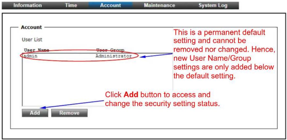
The “Account” tabbed pane allows you to add new Camera User Name and change Password and the surveillance status or User Group. Click the “Add” button to access the security setup dialog (shown below).
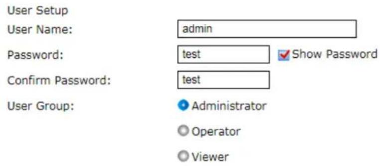
Note:
- A user name and password must contain at least one character.
- Max 14 characters are allowed in user names.
- The first character in user name must be A-Z or a-z.
- Only A-Z, a-z and 0-9 are allowed in the user name and password.
- Max eight characters are allowed in the password.
- The maximum number of users is 20.
- The 'admin' user is default user and cannot be deleted.
Save
- User Name: Enter the new user name to be added into the list (see Note 4 of dialog for proper entry).
- Password: Enter the new password (see Note 4 of dialog for proper entry).
- Confirm password: Enter the password again for authentication (encoded display).
• Show Password: Displays the decoded password when check box is enabled. - User Group: Three group options are available, namely:
Administrator: User is allowed to change Camera settings and perform all Camera functions.
Operator: User is allowed to login "Live View" Webpage and perform all functions within this page. Except changing Video and Audio settings of Camera live stream, other adjustments of Camera parameter are prohibited.
Viewer: User is only allowed to login "Live View" Webpage and perform all functions within this page. Changing Camera settings is prohibited.
Save
: After setups are completed, click "Save" button to apply the settings.
4. Maintenance

System
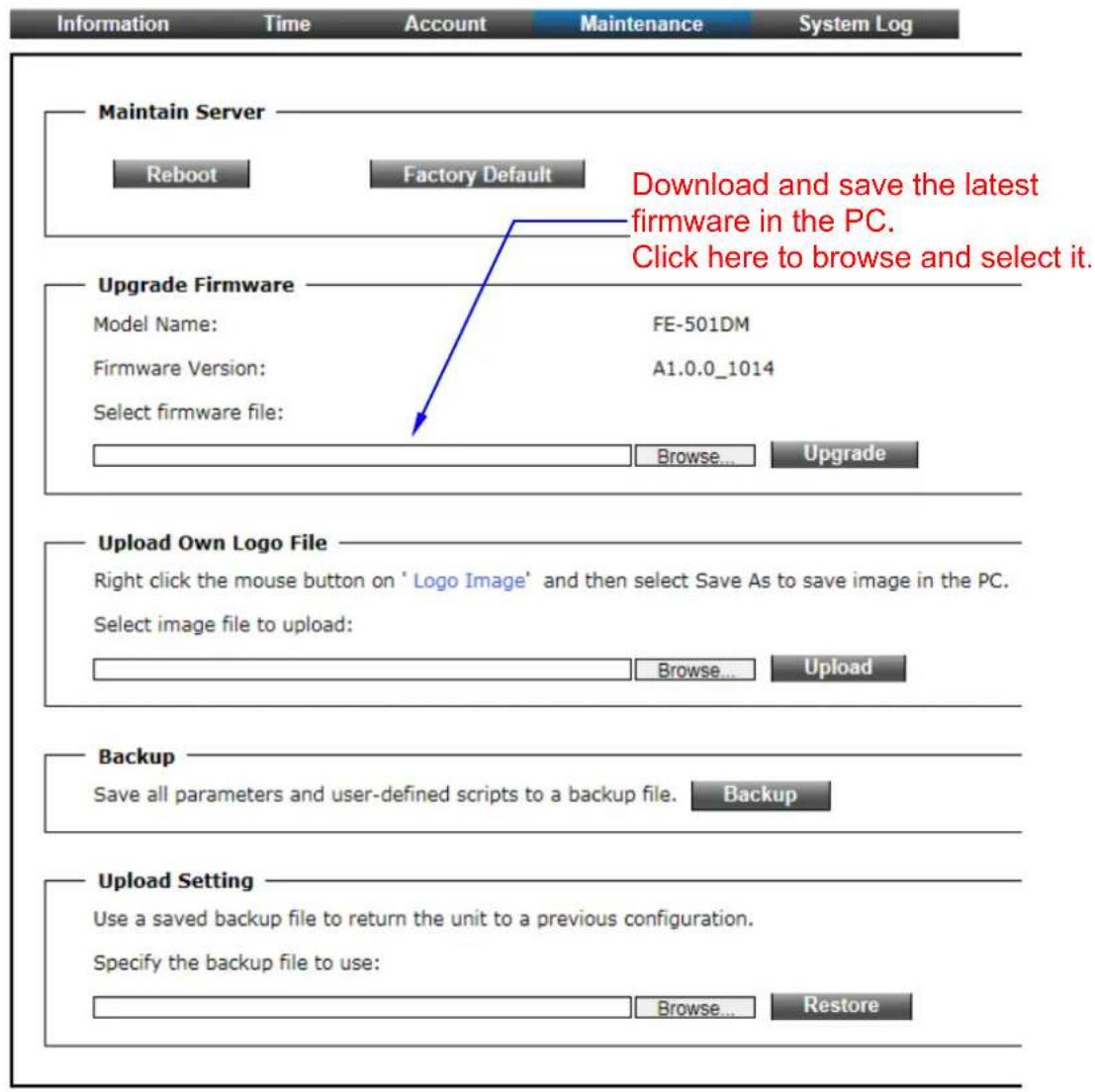
The "Maintenance" tabbed pane allows you to upgrade the firmware with the latest version and to restore the Network Camera settings to factory default.
- Reboot System: Clicking the "Reboot" button allows you to manually reboot the Network Camera.
- Factory Default: Clicking the "Factory Default" button will restore the Network Camera to its factory default settings status. Before Camera system proceed to restore step, there'll be a dialog window popped and then ask if you would like to keep "Network setting" parameters. Besides, all configured data in the "System Time", "Account" and "Maintenance" tab will be remained current.
- Upload Own Logo File: Prepare and save the Logo Image file in the PC, Then follow the below steps to replace Web UI Logo with it.
1) Click the "Browse" button to access and select Logo Image file from PC.
2) Click the "Upload" button to process Logo replacing. When upload process is completed, it's strongly recommended to close and restart Web Browser.
- Upgrade Firmware: Download the latest firmware file from the website by executing the following steps:
1) Click the "Browse" button to access and select the appropriate firmware file from its folder.
※ Please specify the correct firmware version mapped with your camera to upgrade, or there will be danger to damage camera system.
2) Click the "Upgrade" button. The Network Camera will then start to upgrade the existing firmware. When upgrade is completed, the Camera will reboot automatically.
- Backup: Clicking the "Backup" button allows you to manually save Camera's parameters and user settings into a "config_backup.tar.gz" file.
- Upload Setting: This function allows user to restore Camera's backup setting by executing the below steps:
1) Click the "Browse" button to access and select saved "config_backup.tar.gz" file from the PC.
2) Click the "Restore" button to process Camera configuration restore.
5. System Log

System
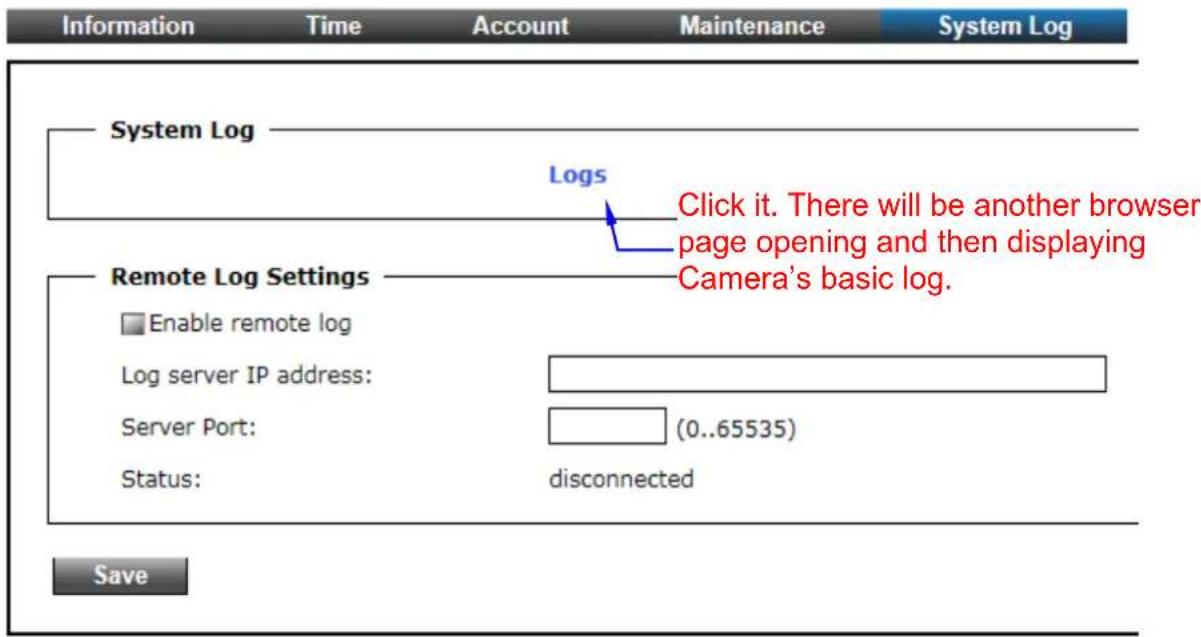
The "System Log" tabbed pane allows you to see Camera's basic log on another browser page or Remote Log Server.
- Remote Log Setting: Check "Enable remote log" selection first; and then manual entering IP address & port setting of Remote Log Server.
Save
: After setups are completed, click "Save" button to apply the settings.
6
Operating IP Camera via iOS/Android Device
6.1 Using IP Camera via iOS/Android Device
You can access into your IP camera via the iOS/Android device. Please follow the setup steps below.
-
Download AirLive CamPro Mobile from APP store/Google play
-
Execute the AirLive CamPro Mobile program
natural_image
Air Live brand logo featuring a security camera icon on a blue background with wireless signal waves (no text or symbols beyond the logo design)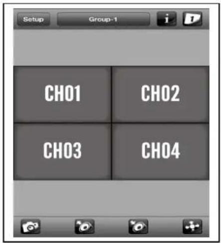
- Click Setup button.
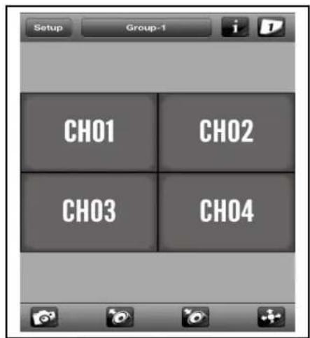
- Setup page appears
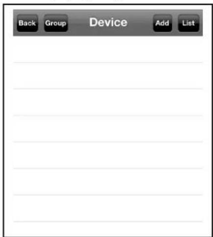
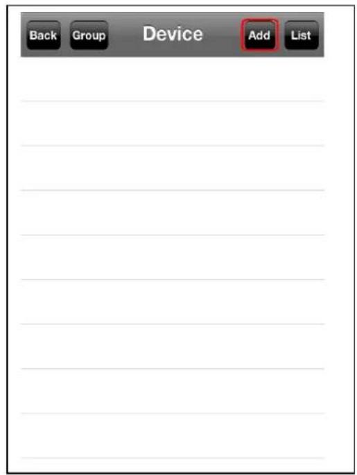
5. Click Add and Auto Search button.
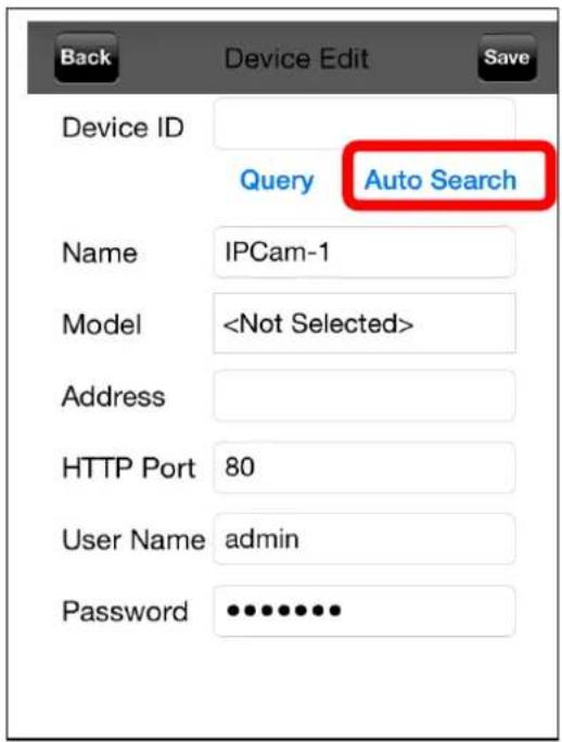
6. Select the camera.
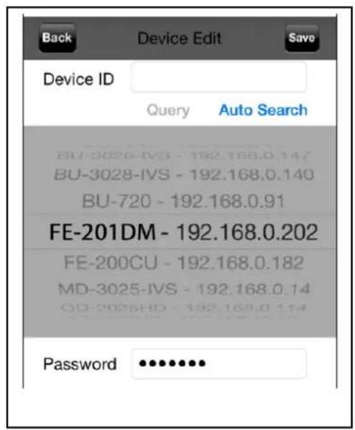
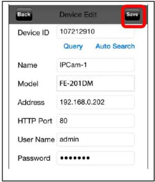
7. Edit the information and User Name/Password, click "Save".
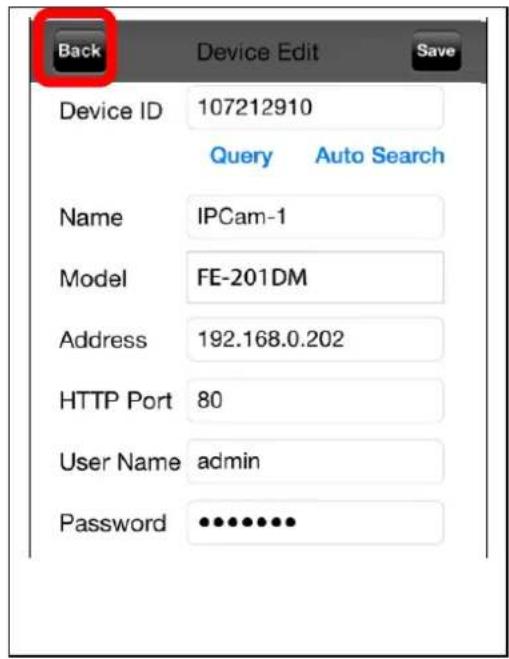
- Click "Back".
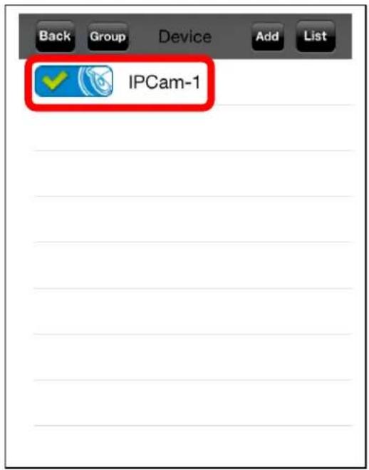
- Select the camera.
- Select the channel to enlarge the video.
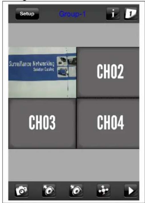
- Camera live view.
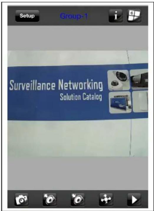
Note: The image is continuous snapshots, not video. Thus, live image can't be recorded here.
- User's Manual
- Air Live®
- Powered by OvisLink Corp.
- Copyright & Disclaimer
- FCC Statement
- Federal Communication Commission Interference Statement
- FCC Caution
- FCC Radiation Exposure Statement
- WEEE Marking Warning:
- Table of Contents
- Overview....1
- Package Contents and Installation....6
- Using IP Camera via Web Browser....14
- Operating the Network Camera ....15
- Configuration ......20
- Operating IP Camera via iOS/Android Device ....55
- 1
- Overview
- Introduction
- Features
- Product Specification
- System Requirement
- 2
- Package Contents and Installation
- Package Content
- Connections
- Power Source Requirement
- Connectors
- Mounting the camera
- Install the Camera in LAN
- Connect to IP Camera
- 3
- Using IP Camera via Web Browser
- Windows Web Browser
- 4
- Operating the Network Camera
- Live View
- Original size
- Digital Zoom
- Snapshot
- Record
- / Microphone
- Display Mode
- Region of Interest
- ePTZ function
- Protocol
- 10.View Options
- Language
- Configuration
- 5
- Configuration
- Network
- General
- Network
- Network Settings:
- PPPoE
- Port Settings:
- Save
- DDNS
- Multicast Tab
- IP Filter
- Add
- Remove
- Video
- Stream
- Video quality settings for stream 1
- Video quality settings for stream 2
- Video quality settings for stream 3
- Video:
- Privacy Mask:
- Video
- Audio
- System
- Event
- Motion Detection
- Video
- Event
- Target to:
- Test E-mail
- √ FTP
- Test FTP
- SD card
- Storage
- Storage
- MicroSD card management:
- Refresh
- Disk management:
- Playback:
- System
- Information
- System
- Time
- Account
- Note:
- Maintenance
- System Log
- 6
- Operating IP Camera via iOS/Android Device
- Using IP Camera via iOS/Android Device
- Click Add and Auto Search button.
- Select the camera.
- Edit the information and User Name/Password, click "Save".
Brand : AIRLIVE
Model : FE-201DM
Category : Security Camera