
BU-3025 - Security Camera AIRLIVE - Free user manual and instructions
Find the device manual for free BU-3025 AIRLIVE in PDF.


| Product Type | Outdoor Bullet IP Camera |
| Model | BU-3025v2 |
| Image Sensor | 1/2.5" CMOS, 3.0 Megapixel |
| Max Resolution | 2048 x 1536 (QXGA) |
| Lens Type | Fixed board lens, 4mm, F1.8 |
| Night Vision | Infrared LEDs, up to 25 meters |
| IR Cut Filter | Mechanical, auto-switching |
| Video Compression | H.264, MPEG4, MJPEG |
| Max Frame Rate | 20 fps @ QXGA; 30 fps @ 1080p |
| Audio | Two-way audio, G.711 codec |
| Network Interface | 10/100Base-T Ethernet with PoE (IEEE 802.3af) |
| Supported Protocols | IPv6, TCP/IP, UDP, HTTP, HTTPS, FTP, SMTP, DHCP, NTP, DNS, DDNS, UPnP, Bonjour, RTP, RTSP, RTCP |
| Local Storage | Micro-SD/SDHC card slot (FAT32) |
| Power Supply | DC 12V or PoE, max 8W |
| Environmental Rating | IP66 weatherproof |
| Operating Temperature | -40°C to 50°C |
| Dimensions (H x W x D) | 208 x 82 x 80 mm |
| Mounting | Wall mount kit included |
| Security | Password protection, IP filter, HTTPS |
| Event Detection | Motion detection, digital input, schedule |
| Digital I/O | 1 DI / 1 DO for external alarms |
| ONVIF | Compatible (ONVIF Standard) |
| Mobile Access | 3GPP, AirLive CamPro Mobile app |
| Web Browser Support | IE, Safari, Firefox, Chrome |
Frequently Asked Questions - BU-3025 AIRLIVE
User questions about BU-3025 AIRLIVE
0 question about this device. Answer the ones you know or ask your own.
Ask a new question about this device
Download the instructions for your Security Camera in PDF format for free! Find your manual BU-3025 - AIRLIVE and take your electronic device back in hand. On this page are published all the documents necessary for the use of your device. BU-3025 by AIRLIVE.
USER MANUAL BU-3025 AIRLIVE
Powered by OvisLink Corp.
Copyright & Disclaimer
No part of this publication may be reproduced in any form or by any means, whether electronic, mechanical, photocopying, or recording without the written consent of OvisLink Corp.
OvisLink Corp. has made the best effort to ensure the accuracy of the information in this user's guide. However, we are not liable for the inaccuracies or errors in this guide. Please use with caution. All information is subject to change without notice
All Trademarks are properties of their respective holders.
FCC Statement
Federal Communication Commission Interference Statement
This equipment has been tested and found to comply with the limits for a Class B digital device, pursuant to Part 15 of the FCC Rules. These limits are designed to provide reasonable protection against harmful interference in a residential installation. This equipment generates, uses and can radiate radio frequency energy and, if not installed and used in accordance with the instructions, may cause harmful interference to radio communications. However, there is no guarantee that interference will not occur in a particular installation. If this equipment does cause harmful interference to radio or television reception, which can be determined by turning the equipment off and on, the A user is encouraged to try to correct the interference by one of the following measures:
■ Reorient or relocate the receiving antenna.
■ Increase the separation between the equipment and receiver.
■ Connect the equipment into an outlet on a circuit different from that to which the receiver is connected.
■ Consult the dealer or an experienced radio/TV technician for help.
FCC Caution
Any changes or modifications not expressly approved by the party responsible for compliance could void the user's authority to operate this equipment. This device complies with Part 15 of the FCC Rules. Operation is subject to the following two conditions: (1) This device may not cause harmful interference, and (2) this device must accept any interference received, including interference that may cause undesired operation. For product available in the USA/Canada market, only channel 1\~11 can be operated.
Selection of other channels is not possible.
This device and its antenna(s) must not be co-located or operation in conjunction with any other antenna or transmitter.
FCC Radiation Exposure Statement
This equipment complies with FCC radiation exposure limits set forth for an uncontrolled environment. This equipment should be installed and operated with minimum distance 20cm between the radiator & your body.
Table of Contents
1. Overview....1
1.1 Introduction....1
1.2 Features....2
1.3 Product Specification ....2
1.4 System Requirement ....5
2. Package Contents and Installation....6
2.1 Package Content ....6
2.2 Connections....6
2.3 Mounting the Camera ....8
2.4 Connect to IP Camera 9
3. Using IP Camera via Web Browser....12
3.1 Windows Web Browser....12
4. Operating IP Camera via Mobile Phone 14
4.1 Using IP Camera via iPhone....14
5. Operating the Network Camera ....17
5.1 Live View....18
5.2 Configuration ....20
6. Configuration ......21
6.1 System....22
6.2 Security....23
6.3 Network....25
6.4 IP Filter....29
6.5 Video....30
6.6 Audio....35
6.7 Motion....36
6.8 PTZ Control ....37
6.9 Event....39
6.10Recording 45
6.11 SDHC....46
6.12Log....48
6.13Device Info....49
6.14 Maintenance .... 49
7. Appendix....51
A. Digital I/O User Guide....51
1
Overview
natural_image
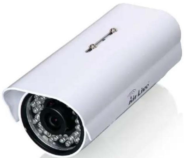
White Air Live security camera with visible lens and sensor array (no text or symbols on body)This user's guide explains how to operate this camera from a computer. A user should read this manual completely and carefully before you operate the device.
1.1 Introduction
AirLive BU-3025 v2 is high-end 3.0 MegaPixel (MP) network camera which is designed for professional outdoor surveillance and security applications. This 3.0MP IP camera offers many improvements in image quality as comparing to the conventional surveillance cameras. Users are able to view live video streaming over the Internet, and it is not the only one of the benefits for using AirLive IP Camera.
It is also designed to offer high-performance surveillance, and it is equipped with PoE port which allows power and data to be transmitted via a single Ethernet cable. This useful function provides an easier installation, lower cabling costs and allows placement of AirLive PoE cameras in locations without access to electrical source.
With the IP-66 waterproof housing, AirLive BU-3025 v2 suits for environments such as stairs, main entrance, street, and basement.
The device is accessible via the LAN or Internet connection. Connect your device directly to a local area network or xDSL modem, and with Microsoft® Internet Explorer, you get instant, on demand video streams. Within minutes you can set up the device to capture a video sequence to a PC. The live video can be uploaded to a website for the world to see.
1.2 Features
This manual will illustrate the steps of how to setup and operate this IP camera, so you'll also soon be enjoying the benefits of these product features:
• 3MegaPixel CMOS H.264 IP Camera
- Compatible with ONVIF Standard
- Up to 20fps at QXGA Resolution and up to 30fps @1080p Full HD
• Support 802.3af Power over Ethernet Standard
- Mechanical IR-Cut Filter Removable
• Built-in Micro-SD Memory Card Slot for Local Storage
• IP-66 Weatherproof Housing for Most of Environments
• Equips High Illuminate IR LED, Project up to 25 Meters!
• Support H.264, MPEG, MJPEG
• Support Two-Way Audio
1.3 Product Specification
| Model BU-3025v2 | ||
| Camera | Camera Type Outdoor Bullet Type | |
| Max Resolution 2048 x 1536 | ||
| Image Sensor 1/2.5" CMOS image sensor | ||
| Sensor Resolution 2592 X 1920 | ||
| Lens Type | Board Lens | |
| 4mm/F1.8 | ||
| Night Vision Built-In Removable IR Cut Filter | ||
| Max IR Distance 25M | ||
| IR LED 5ph*30pcs | ||
| Minimum Illumination | Color: 0.05 Lux@30IREB/W: 0 Lux @ IR ON | |
| Mechanical IR-Cut Filter | Yes | |
| Auto Iris none | ||
| Viewing Angle D | 70.2°, H58.7°, V45.7° | |
| Analog Video Out Yes | ||
| Video | Video Compression | H.264 High/Main/Baseline Profile, MPEG4 Simple Profile and MJPEG |
| Video Profile 20 | ||
| Resolution and Frame Rate | 20 fps @ 2048 x 1536 | |
| 30 fps @ 1920 x1080 | ||
| 30 fps @ 1280 x960 | ||
| 30 fps @ 1280 x 720 | ||
| 30 fps @ 720 x 480 | ||
| 30 fps @ 640 x 480 | ||
| 30 fps @ 320 x 240 | ||
| Streaming | Multi-profile streaming | |
| Streaming over UDP, TCP, or HTTP | ||
| M-JPEG streaming over HTTP (for non IE browser) | ||
| 3GPP mobile view | ||
| Configurable frame rate and bandwidth | ||
| Support both CBR and VBR | ||
| ROI | none | |
| Image Processing | AE, AWB | |
| Noise reduction | ||
| Color, brightness, sharpness, contrast, Hue | ||
| Mirror/Flip | ||
| Text, time and date OSD | ||
| Digital Zoom 10X | ||
| Audio | Audio Encoder G | 711 μ-law |
| Audio Streaming Two-way | ||
| Audio Input/Output speaker port and microphone port | ||
| Network | Ethernet | One RJ45 Port; IEEE 802.3u Compliant 10/100 Mbps Fast Ethernet with Auto-MDIX |
| PoE IEEE802.3af | ||
| Wireless | None | |
| Supported Protocols | IPv6, TCP/IP, UDP, ICMP, DHCP, NTP, DNS, DDNS, SMTP, FTP, HTTP, HTTPS, Samba, PPPoE, UPnP, Bonjour, RTP, RTSP and RTCP | |
| Security | Password protection | |
| IP filter | ||
| HTTPS | ||
| Users Up to 20 simultaneous users | ||
| LED and Button | Power LED Amber Color | |
| Link/Act. LED Green Color/Flash Green | ||
| Reset Button | Reboot and Factory Default(Push and Hold Over 5 Sec) | |
| General | Network Processor DSP Base | |
| System ROM 128MByte NAND Flash | ||
| System RAM 128Mbyte DDR SDRAM | ||
| Power Supply DC12V | ||
| FAN NO | ||
| Power Consumption | 8 Watts Max. | |
| Connector | RJ-45 10BaseT/100BaseTX | |
| 12V DC power jack | ||
| Microphone/Speaker jack | ||
| DIDO | ||
| Reset button | ||
| BNC | ||
| Environment | Operation: Temp: -40°C ~ 50°CHumidity: 20% ~ 85% non-condensing | |
| Storage: Temp: -15°C ~ 60°CHumidity: 0% ~ 90% non-condensing | ||
| SD card slot Micro-SD/SDHC | ||
| Dimension | HxWxD:208x82x80 | |
| System Integration | Software | CamPro Express 64,CamPro Professional |
| Search & Installation- IP Wizard II | ||
| Event Triggers | Motion detection | |
| External input via DI interface | ||
| Motion Detection | Up to 3 zones | |
| Event handler | FTP or NAS file upload | |
| E-mail alter | ||
| HTTP, and TCP notification | ||
| DO (digital output) alarm | ||
| UPNP | Yes | |
| Application Programming | ONVIF | |
| Open API for software integration | ||
| Interface | SDK | |
| Video Buffer Pre- and post- alarm buffering | ||
| Alarm Events | File upload via FTP, NAS, E-mail | |
| Notification via email, HTTP, and TCP | ||
| External output activation | ||
| Micro-SD | ||
| Continuous recording | Yes | |
| Viewing System | OS Windows® XP, Vista, 7 | |
| Browser IE 6.0 or later, Firefox 2.0 or later, Safari | ||
| Cell Phone With 3GPP player | ||
| Video Player VLC, Quick Time, Real Player, Core Player | ||
1.4 System Requirement
For normal operation and viewing of the network camera, it's recommended that your system meets these minimum requirements for proper operation:
| Item | Requirements |
| CPU Pentium-4 3 | 6 GHz or higher |
| VGA Monitor Resolution1280 x 1024 or higher | |
| RAM Minimum 1 GB of RAM | |
| Operating System Window XP, Vista or Windows 7 | |
| Web Browser Internet Explorer 7 or later; Apple Safari; Firefox; Google Chrome | |
| Cell Phone | 3GPP Player |
Note: Please keep updating the latest Windows software and service package. (Ex: Net Framework, Windows Media Player, Enhance ActiveX Security)
2
Package Contents and Installation
2.1 Package Content
A user can find the following items in the package as below:
- AirLive BU-3025 v2 is the main element of the product.
- Bundle CD includes Setup Wizard II, CamPro Express64, Quick Start Guide, User Manual, and Video.
- Quick Start Guide provides important information and instructions for installing this device.
- Accessory Package including Wall Mount Kit & Wall Mount Stand
- Power Adapter: 12V DC electric power adapter
2.2 Connections
Power Source Requirement
This camera can work with 802.3af POE switch without the power adapter. However, if you don't have POE switch, you can use power adapter in the box to provide power to camera.
Switch/Connector
There are various connectors of AirLive BU-3025 v2 as shown in the figures below. Please refer to the diagrams and tables accompanied with for using of each switch / connector.
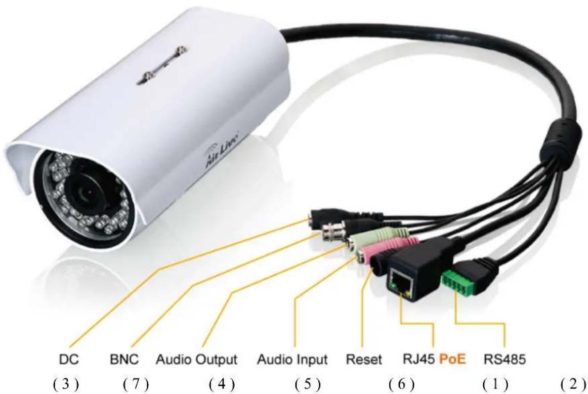
- RJ45 LAN socket: Connect to PC or Hub/Switch.
For connections to 10Base-T Ethernet or 100Base-TX Fast Ethernet cabling. This Ethernet port built N-Way protocol can detect or negotiate the transmission speed of the network automatically. Please use Category 5 cable to connect the Network Camera to a 100Mbps Fast Ethernet network switch or hub.
In the LAN socket, there are two LEDs embedded:
LAN LED (green color)
Green Link Light indicates good network connection.
Power (orange color)
This LED is used to indicate whether DC power is on or not.
- RS485:
| Item | Description |
| - : RS485- RS-485 | |
| + : RS485+ | |
| 1 : DO (Digital Output) | |
| 2 : GND (Ground) | |
| 3 : DI (Digital Input) |
- DC-in: The input power is 12VDC/2A.
- Audio Output
- Audio Input
- Reset Button: This button is used to restore all the factory default settings.
- TV out: BNC Connector
2.3 Mounting the Camera
Fix the camera with bundle wall mount kit as below.
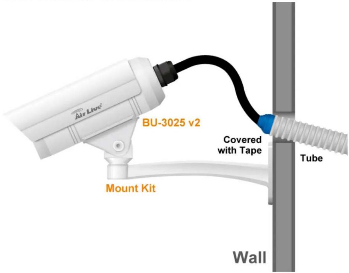
1. Plug an Ethernet cable into the Camera
Connect an Ethernet cable to the LAN socket and attach it into the network.
2. Connect the external power supply to Camera
Connect the attached power adapter to the DC power jack of the camera.
Note: Use the power adapter, 12VDC, included in the package and connect it to wall outlet for AC power.
Once you have installed the camera well and powered it on, the power LED (orange) will turn on later. The power LED turns on, which means the system is booting up successfully. Furthermore, if you have a proper network connection, and access to the camera, the LAN LED (green) will flash.
2.4 Connect to IP Camera
- Insert the bundle CD into your PC/Laptop.
- Auto Run Screen then shows up; click "Install Software "Camera IP Finder Utility" to install the configuration tool software.
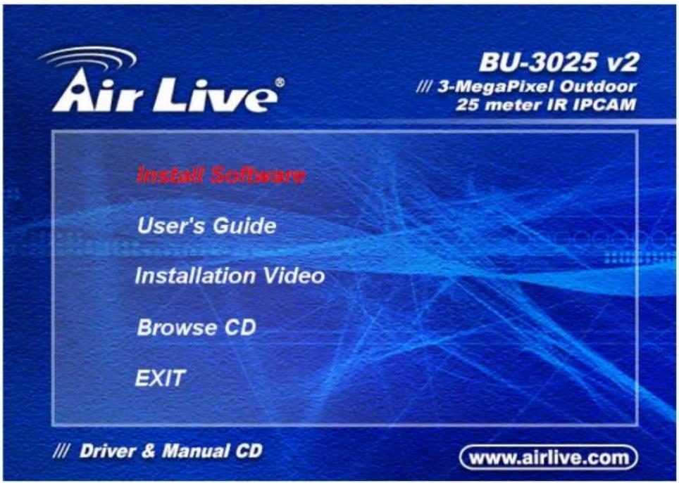
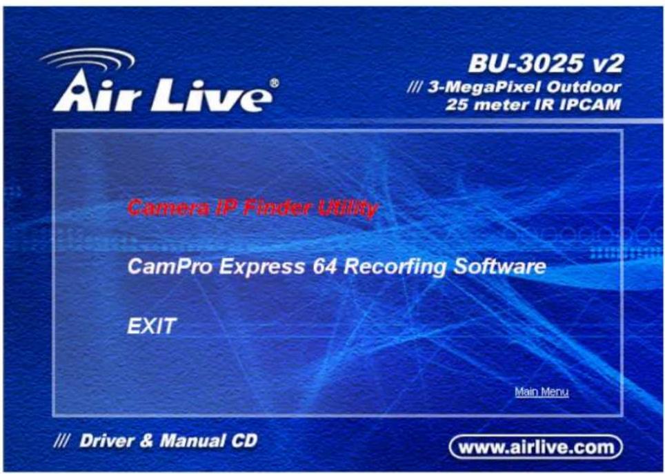
- After completing installation, run the configuration tool software.
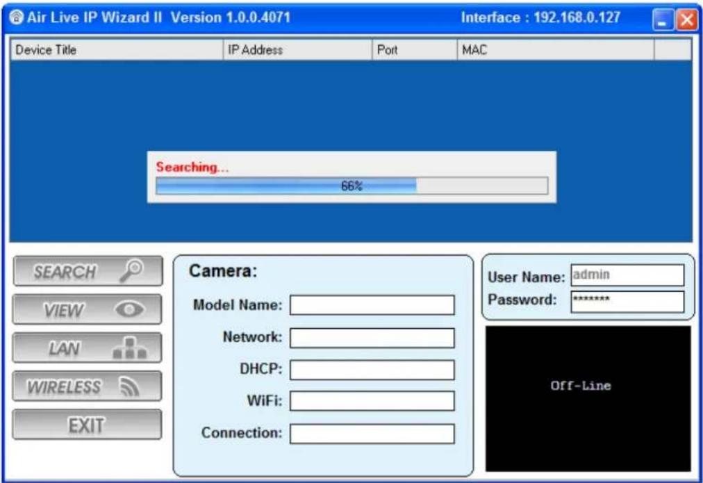
- The Software scans the network and finds the IP Camera and then lists them in the dialog box.
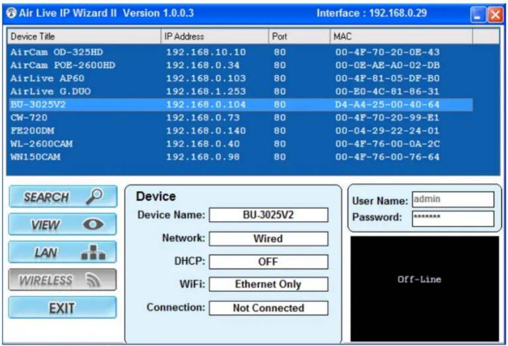
- If the Camera's IP address is in the same IP segment as your LAN, select the founded IP Camera and double click on the item. Then, the default browser will show up and connect to the IP camera's Web automatically.
3
Using IP Camera via Web Browser
3.1 Windows Web Browser
- Open your web browser, and enter the IP address or host name of the IP camera in the Location / Address field of your browser.
Note: If you only want to view the video without accessing Setting screen, enter "http://
- Use the default account "admin" and default password "airlive".
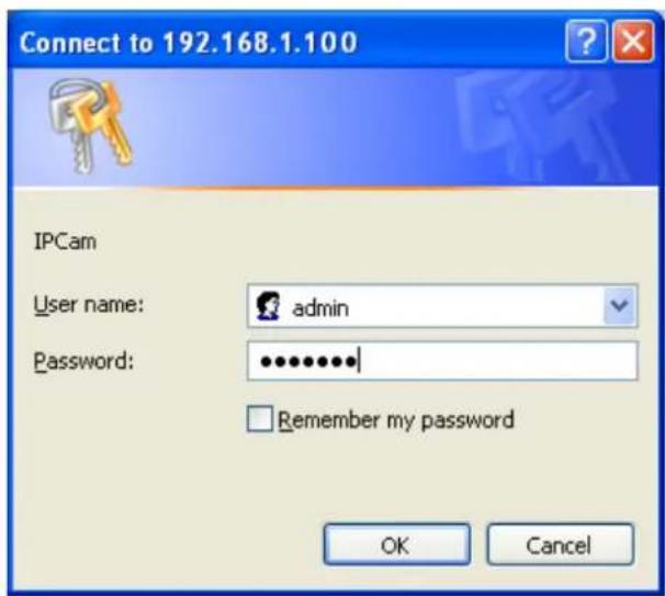
Note: The default user name "admin" and the password "airlive" are set at the factory for the administrator.
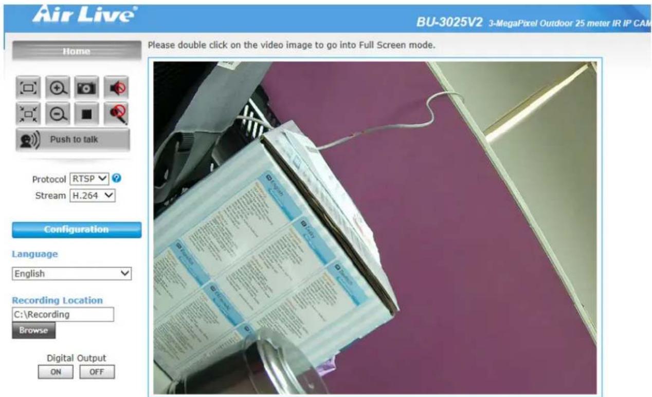
- The monitor image will be displayed in your browser. In the left side of main window, you can configure the settings you want. For more details, you can check the following chapters.
©copyright 2013 All Right Reserved
4
Operating IP Camera via Mobile Phone
4.1 Using IP Camera via iPhone
You can access to your IP camera via your iPhone. Please follow the setting process below. Then you can see the live view via iPhone.
- Download AirLive CamPro Mobile from APP store
natural_image
Blue square icon with white camera lens and 'Air Live' branding (no additional text or symbols)- Execute AirLive CamPro Mobile
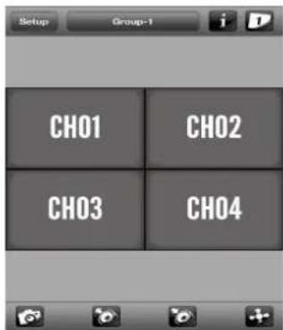
- Click Setup button.
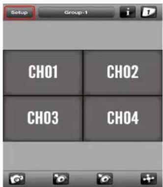
- Setup page appears

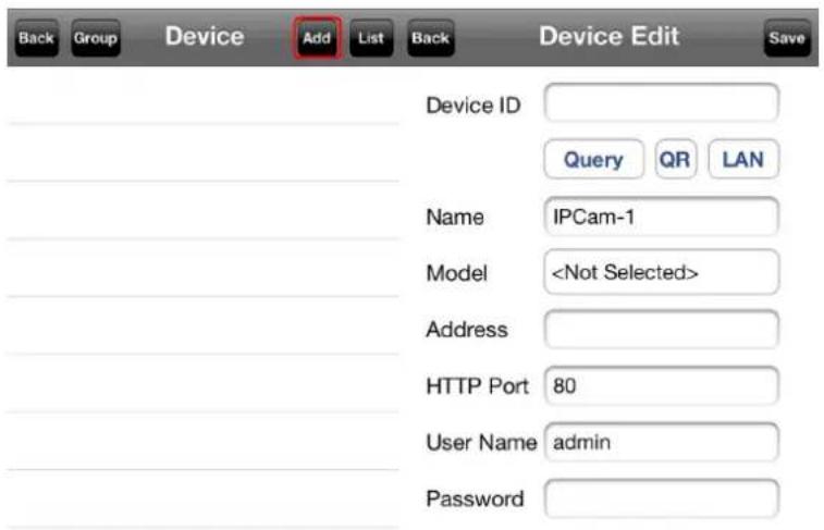
5. Click Add button.
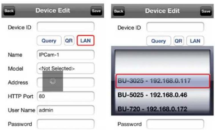
6. Click LAN button and select the camera.
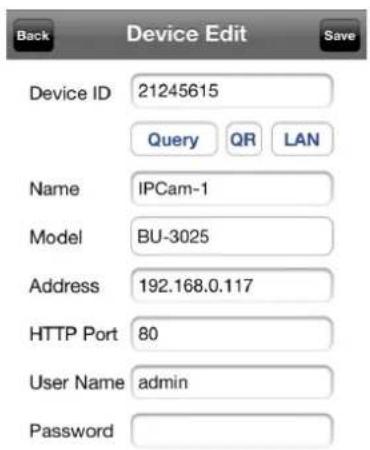
- Model, Address, HTTP Port info appear on the page.
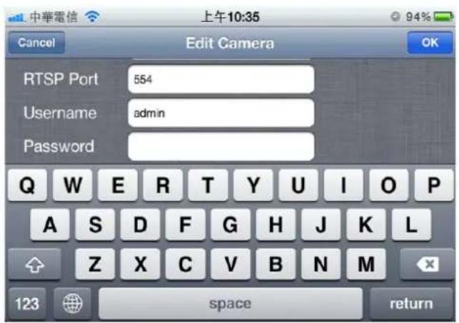
- Key-in Username and Password then click OK button.
- Click Live View button.
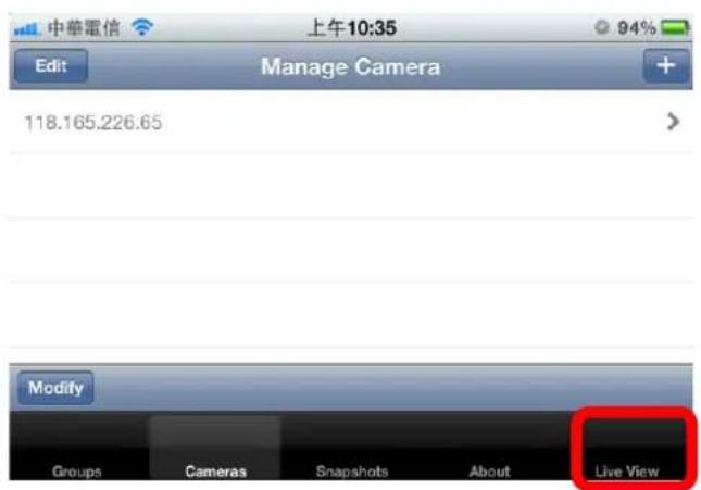
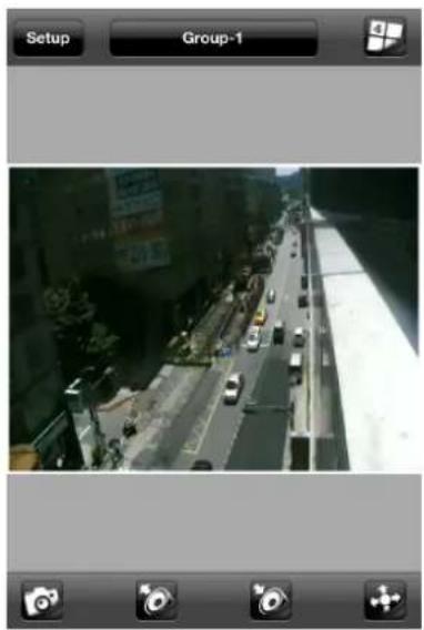
- The video appears on the main screen.
natural_image
Street view from a mobile phone setup showing a multi-lane highway with vehicles and buildings in the background (no readable text or symbols)Note: The image is continuous snapshots, not video. Thus, live image can't be recorded here.
5
Operating the Network Camera
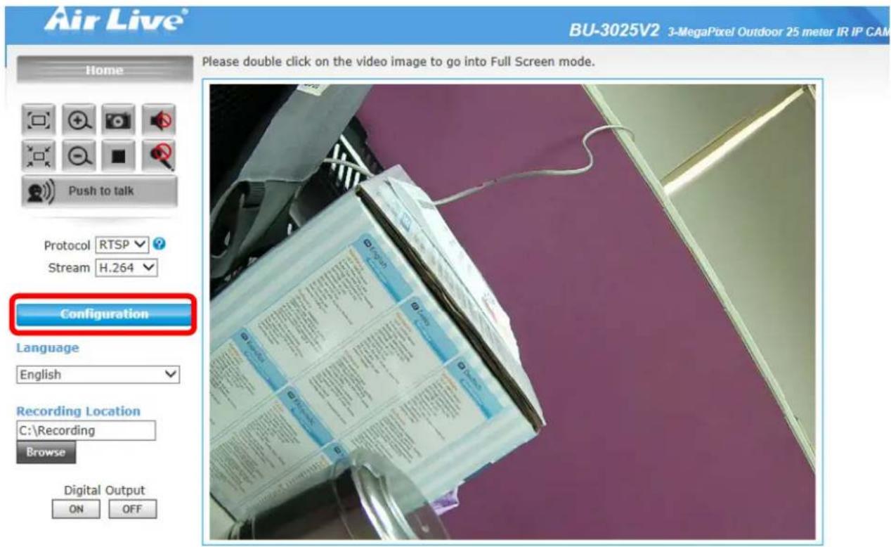
Start-up screen will be as follow no matter an ordinary users or an administrator.
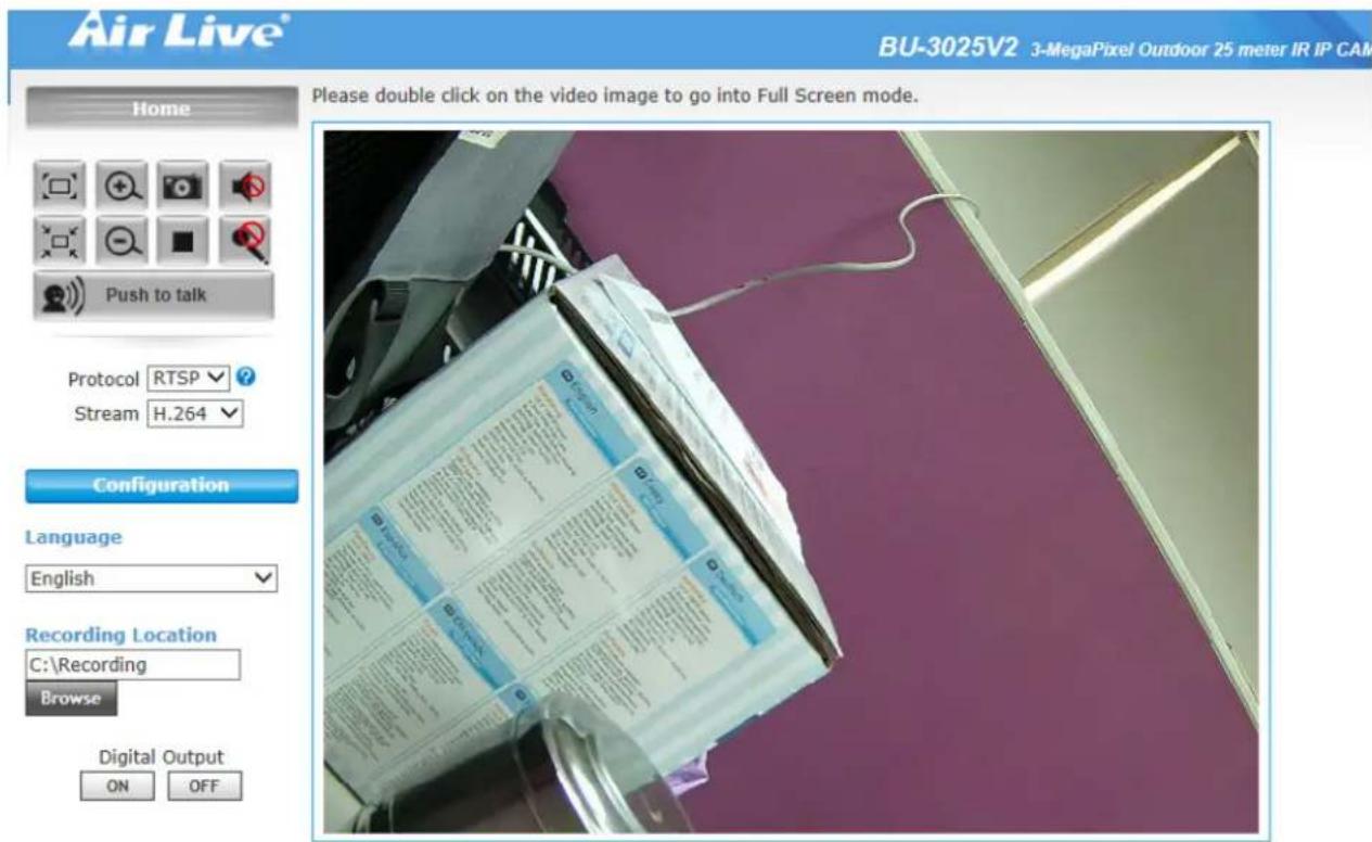
In the left side, you can control Live View in your main Browser. The functions include below.
©copyright 2013 All Right Reserved
5.1 Live View
1. Language
Multiple languages are supported, including the following for the viewer window interface.

2. Stream
The device supports multi-profile function for H.264, MEPG4 and JPEG simultaneously. A user can choose the proper and/or preferred profile which is listed here.
3. Protocol
A user can select proper streaming protocol according to network environment.
4. Digital Output
Switch digital output interface on or off.
5. 2-Way Audio
The device supports 2-way audio function. A user can choose to enable or disable this function by toggling the icon below.

: Disable speaker function.

: Enable speaker function.

: Disable audio uploading function.

: Enable audio uploading function.
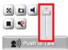
6. Volume
Click Speaker button to activate this function. Scroll the control bars to adjust the audio attribute.
7. Original size / Preview Size

Switches live image view between original size (full size: 3MegaPixels) and preview size (smaller size).
8. Digital Zoom

From 1X to 10X, so you can see objects in video in detail.
Please note: that digital zoom uses computer algorithm to enlarge the video and some details may lost. If you need to focus on detail of specific objects in video view, please use optical zoom ring on lens set of IP camera.
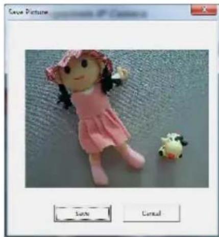
9. Snapshot

Take a snapshot or camera video and save image file on your computer. When you click this button, a new window will appear.
natural_image
Illustration of a pink doll in a pink dress next to a small white sheep toy, displayed within a software window titled 'Save Picture' (no text on the doll or background)Click 'Save' button when you see the image you wish to save, and you'll be prompted to indicate the folder on your computer to save image file.
If you changed your mind and don't want to save image file, click 'Cancel'.
10. Record

Click Record to activate this function. Press Record button to start recording. The video file is saved as ASF format into your local PC. While you want to stop it, press Stop to stop recording.
Recording Location
Browse
11. Recording Location
Select Recording Location to select the save path and file name prefix, select OK to continue.
5.2 Configuration
Click "Configuration" for the camera settings. In the left side of main menu, you can see many settings. For more detail information, you can refer to Chapter 6.
©copyright 2013 All Right Reserved
6
Configuration
Click the Configuration as below.
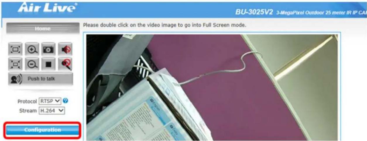
Pop-up 14 sub-menus as below
| Item Action | |
| System Configure basic IP camera settings like hostname and time. | |
| Security Configure IP camera's login account. | |
| Network | Configure Network settings such as DHCP, PPPoE and UPnP |
| IP Filter You can | enter different user's IP address which are allowing enter or denying by the device |
| Video Configure bit rate and frame rate of video profiles | |
| Audio | Configure audio parameters |
| Motion Setup Motion detection | |
| PTZ Control Configure Pan tilt control via RS-485 connection | |
| Event Setup Event server, Motion Detection, I/O Ports and Event configuration. | |
| Recording Setup External storage Recording | |
| SDHC Status and configuration of Micro-SD card | |
| Log | Check the usage log of IP camera |
| Device info | Check the information and network settings of this IP camera. |
| Maintenance | Setup maintenance function of this IP camera |
DDNS, RTSP,
6.1 System
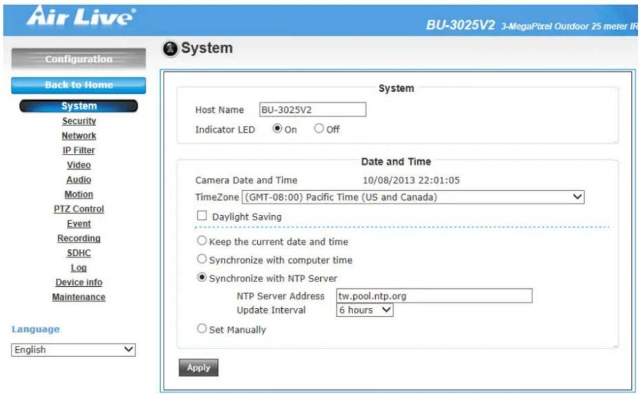
In this menu, you can configure basic IP camera settings like hostname and time.
1. System
- Host Name
You can enter the name of this unit here. It's very useful to identify the specific device from multiple units. The information will be shown on IPWizard II once the device is found.
- Indicator LED
Turn on or off Indicator LED.
2. Date and Time
- Time Zone
Set the time difference from Greenwich Mean Time in the area where the device is installed.
- Daylight Saving
Disable or enable the daylight saving adjustment.
- Keep the current date and time:
Select this option and date / time setting will not be changed when you click 'Apply' in the page. You can check 'Camera Date and Time' item in this page to know IP camera's current date and time setting.
- Synchronize with computer time
Click this option to enable time synchronization with PC time.
- Synchronize with NTP Server
Click this option if you want to synchronize the device's date and time with those of time server called NTP server (Network Time Protocol).
- Set Manually
Click this option to set time and date manually..
When you finish with above settings, click 'Apply' button to save changes
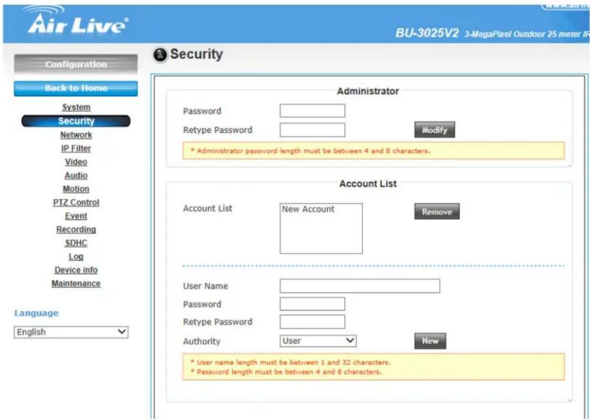
6.2 Security
In this menu, you can configure IP camera's login account. There are three kinds of account:
- Administrator
An administrator can view IP camera's video and make changes of camera setting.
For the first time use (default value), input the
User Name: admin
Password: airlive
- User
A user can view IP camera's video and see settings, but can't make any change.
- Guest
A guest can view IP camera's video only.
There can be multiple users, but only one administrator is allowed, and you can't change administrator's user name (it will always be 'administrator').
Here are the descriptions of every setup item:
| Item | Description |
| Password / Retype Password (Administrator) | Input administrator's new password in both ‘Password’ and ‘Retype Password’ field, and click ‘Modify’ button to change administrator's password.Please note: Don't forget administrator's password! Or you'll need to reset IP camera's all settings to get administrator's password recovered. |
| Account List | Here lists all users existed in IP camera. If you want to remove one user, click it in the list, and then click ‘Remove’ button.If no user is existed, ‘New Account’ message will be shown here. |
| User Name Input new | user's username here. User name must be greater than 1 character and less than 32 characters. |
| Password / Retype Password | Input this user's password in both ‘Password’ and ‘Retype Password’ field. |
| Authority To define this | user's access privilege, select ‘User’ or ‘Guest’ in dropdown menu.When you finish inputting new user's information, click ‘New’ button to create a new user. |
6.3 Network
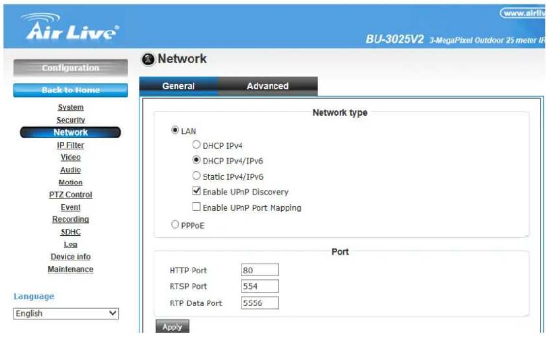
In this menu, you can configure IP camera's network setting.
1. General
Here are the descriptions of every setup item:
• LAN:
Select this option to assign an IP address to LAN port (or obtain an address from DHCP server automatically).
Available options are:
- DHCP IPv4: Obtain an IPv4 IP address from DHCP server on LAN automatically.
- DHCP IPv4 / IPv6: Obtain both IPv4 and IPv6 address from DHCP server on LAN automatically.
- Static IPv4 / IPv6: Assign an IPv4 / IPv6 address to IP camera manually. If you don't have a DHCP server on your local area network, you must use this option to specify an IP address.
- IP Address (IPv4): Input IPv4 IP address*
- IP Address (IPv6): Input IPv6 IP address*
- Prefix Length: Input IPv6 IP address' prefix length (0-128)
- Subnet Mask: Input subnet mask
- Gateway: Input gateway address
- Primary DNS: Input DNS server's IP address
- Secondary DNS: Input backup DNS server's IP address, you can leave this field blank.
* You can leave this field blank, if you only wish to use IPv4 or IPv6 IP address.
Enable UPnP Discovery: Check this box to enable other devices on network to discover the presence of this IP camera by UPnP. It's recommended to enable this function.
Enable UPnP Port Mapping: When UPnP is enabled, check this box to enable UPnP's port mapping.
| IP Address (IPv4/IPv6) | Enter the IP address of the camera. The default setting is 192.168.1.100. |
| Subnet Mask | Enter the Subnet Mask of the camera. The default setting is 255.255.255.0. |
| Default Gateway | Enter the Default Gateway of the camera. The default setting is 192.168.1.254 |
| Primary/Secondary DNS | DNS (Domain Name System) translates domain names into IP addresses. Enter the Primary DNS and Secondary DNS that are provided by ISP. |
- PPPoE:
Select this option to use PPPoE to connect to network. You have to input PPPoE username and password assigned by network operator to get connected.
- HTTP Port:
Input IP camera's web connection port number here. When this port number is changed, you need to change web browser's port number you used to connect to IP camera.
For example, if the IP camera's IP address is 192.168.2.3 and you changed HTTP port number to 82, please input 'http://192.168.2.3:82' in web browser's address bar to access IP camera's web configuration interface.
- RTSP Port:
Input RTSP port number. When this port number changes, you must change corresponding settings in external network devices (NVR or CMS software) so they can receive this IP camera's video.
- RTP Data Port:
Input RTP data port number here.
When you finish with above settings, click 'Apply' button to save changes.
2. Advanced
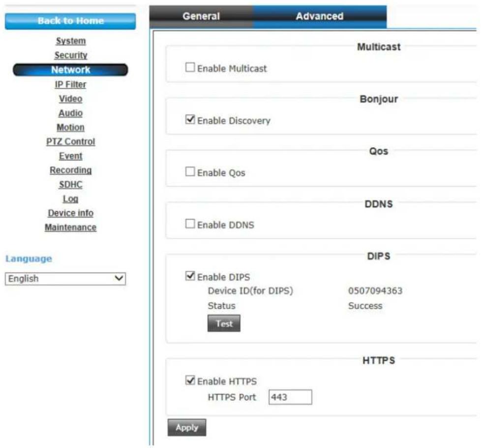
You can setup advanced network settings in this page. This page is intended for advanced settings only, and this IP camera will work fine even you don't make any changes to this page.
- Multicast:
Enable video multicast:
Multicast Group Address: Input multicast group address here, must be an address between 232.0.0.0 to 232.255.255.255.
Multicast video port: Input port number for video multicast here.
Multicast RCTP video port: Input port number for RCTP video here.
Multicast audio port: Input port number for audio here.
Multicast RCTP audio port: Input port number for RCTP audio here.
Multicast TTL: Input TTL value for multicast here.
- Bonjour:
If you're using Mac OS and you have Bonjour installed, you can use it to discover this IP camera.
- QoS:
Enable QoS to improve the data transfer priority of this IP camera (Your local area network must support QoS).
You can select Video / Audio's QoS DSCP value (0 to 63), or both video and audio.
- DDNS:
Enable DDNS support if your ISP assigns dynamic IP address to you. You must register a dynamic IP service first. Currently this IP camera supports Dyndns and TZO dynamic IP service.
Provider: Select dynamic IP service provider.
Host Name: Input the host name you obtained from dynamic IP service provider.
User name: Input user name used to login dynamic IP service provider.
Password: Input the password used to login dynamic IP service provider.
• DIPS ID:
It's a unique number of each device for identification and this ID is used for DIPS. This function now is reserved for future use.
- HTTPS:
Check 'Enable HTTPS' box to enable HTTPS channel to encrypt transferred data. You can also define HTTPS port number in 'HTTPS Port' field if you don't want to use default value '443'.
6.4 IP Filter
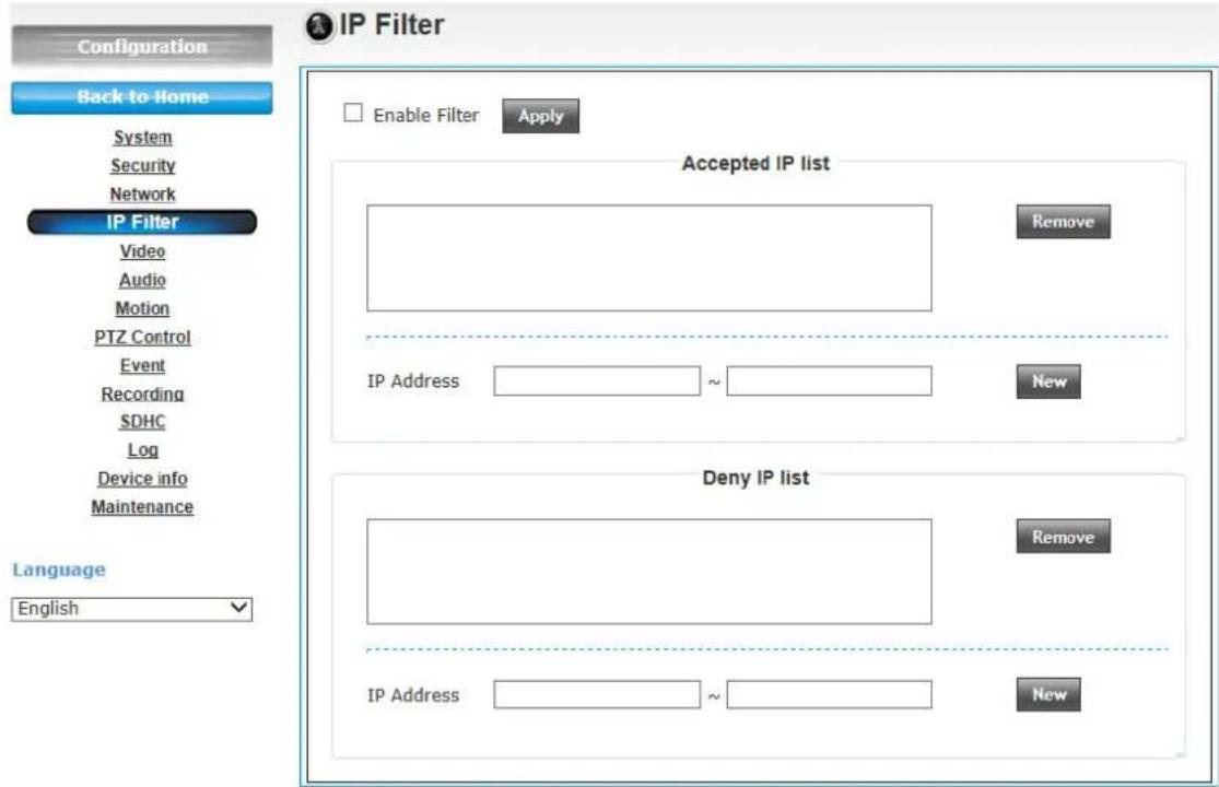
When this IP camera is directly connected to Internet and not protected by firewall, this function acts like a mini built in firewall to protect the safety of this IP camera and avoid attacks from hackers.
| Item | Description |
| Enable Filter Check | this box to enable IP address filter, uncheck thisBox to disable this function. |
| Accepted IP list Here lists all IP address that can build connections to this IP camera.If you want to remove a set of IP address from the list, click on the IP address and click ‘Remove’ button. | |
| IP Address (Accepted IP list) | Input the starting and ending IP address of IP address you wish to accept connections here. IP camera will only accept connections established from these IP address.If you want to specify one IP address only, input the same IP address in both field.Click ‘New’ button to add IP address into accepted IP list. |
| Deny IP list Here lists all IP address that cannot build connections to this IP camera. If you want to remove a set of IP address from the list, click on the IP address and click ‘Remove’ button. | |
| IP Address (Accepted IP list) | Input the starting and ending IP address of IP address you wish to deny connections here. IP camera will deny connections established from these IP address.If you want to specify one IP address only, input the same IP address in both field.Click ‘New’ button to add IP address into deny IP list. |
When you finish with above settings, click 'Apply' button to save changes.
6.5 Video
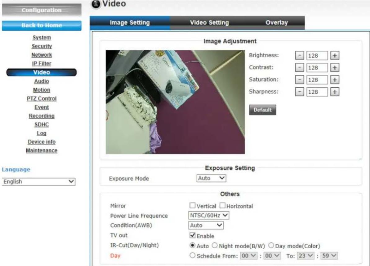
There are 3 sub-menus in this menu: Image Setting, Video Setting, and Overlay, which can be accessed by tabs on the top:
1. Image Setting
You can adjust the image parameters in this page.
- Brightness /Contrast /Saturation /Sharpness:
Control the image parameters. Click ‘-’ to decrease value, or click ‘+’ to increase value. You can also input the value in the field directly.
- Default:
Check "Vertical" and "Horizontal" box to flip the image vertically or horizontally, this will help to correct the orientation of image when IP camera is hanged bottom up by camera holder.
You can click both "Vertical" and "Horizontal" box at the same time.
• Power Line Frequency:
Select the frequency of power line of the place you're using this IP camera. This will help to reduce the flicker of certain lights in the image.
- Condition:
Select the condition that you'll be using this IP camera from dropdown menu.
Auto: IP camera will adjust its parameters automatically.
Night: You'll be using this IP camera in dark places where lights are insufficient.
• TV Out:
Click "Enable" box to enable its "VIDEO OUT" function for connections and video sending to TV monitors or DVRs.
- IR cut:
An IR cut filter is built in this IP camera to reduce the effect of IR lights (which will change the color of image and makes it looks different than what you see through your eyes), and most of IR lights are coming from sunlight.
You can select the behavior or IR cut filter:
Auto: IR filter will act automatically. If you don't know wheatear you should use IR filter or not, select this option.
Always ON: IR filter is always on.
Always OFF: IR filter is always off.
• Day:
Select the condition that you'll be using this IP camera from dropdown menu.
Auto: IP camera will adjust its parameters automatically.
Night: You'll be using this IP camera in dark places where lights are insufficient.
2. Video Setting
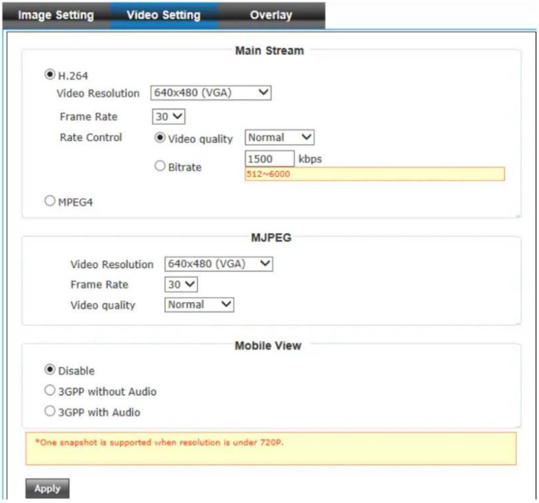
You can adjust the video transfer parameters in this page.
Here are the descriptions of every setup item:
| Item | Description |
| H.264 /MPEG4 Select the compression of main stream: H.264 / MPEG4. | |
| Video Resolution | Select video resolution.- H.264:2048x1536 (QXGA) / 1920x1080 (1080p)1280x960 (960p) / 1280x720 (720p)720x480 (D1) / 640x480 (VGA)320x240 (QVGA)- MPEG4:1920x1080 (1080p) / 1280x960 (960p)1280x720 (720p) / 720x480 (D1)640x480 (VGA) / 320x240 (QVGA)MJPEG:1280x720 (720p) / 720x480 (D1)640x480 (VGA) / 320x240 (QVGA)Please note that some video resolution is not available when video encoder is ‘MPEG4’.When network speed is insufficient, select a lower video resolution will help. |
| Frame Rate Select video frame rate. Please note that some frame rate is not available when video encoder is ‘H.264’.When network speed is insufficient, select a lower frame rate will help. | |
| Rate Control Select video bit rate. You can control bit rate by both ‘Video quality’ and ‘Bitrate’:- Video quality: There are 5 levels of video quality, select ‘very high’ to improve video quality but consumes more network bandwidth, and select ‘very low’ will decrease video quality and consumes less network bandwidth.- Bitrate: Input video’s bit rate directly. It must an integer between 512 and 6000. Higher bit rate provides better video quality, but consumes more network bandwidth. | |
| Mobile View Checking the radio box to enable remote access when you need to remote access via mobile phone. | |
When you finish with above settings, click 'Apply' button to save changes.
Note: MJPEG options are only available for portable devices like cell phone. The resolution is under 1280 x 720 (720P). The UI page will pop up when the resolution of H.264/MPEG4 is 720P or below like hereunder.
3. Overlay
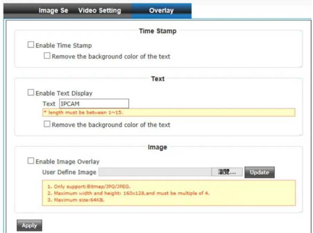
You can adjust the video overlay parameters in this page.
Here are the descriptions of every setup item:
| Item | Description |
| Enable Time Stamp | Check this box to enable overlaying time stamp on video. |
| Remove the background color of the text (for Time Stamp) | Check this box to remove time stamp's background color. You may find this will help the readability of time stamp text in some cases. |
| Enable Text Display | Check this box to display certain text on video, this will help when you need to identify certain IP camera when you have a lot of IPcameras.Please input the text in ‘Text’ field. You can input up to 15 characters. |
| Remove the background color of the text (Text) | Check this box to remove custom text’s background color. You may find this will help the readability of text in some cases. |
| Enable Image Overlay | Check this box to overlay a specific image on video, so you can show certain text / picture on the video and help people to identify this IP camera.Click ‘Browse’ button to pick a picture on your computer, then click ‘Update’ button to use the picture. Please note that there are certain restrictions:- Select .bmp / .jpg / .jpeg image files only.- Image’s resolution should be less than 160 x 128, and can be divided by 4.- Do not upload image files that size is greater than 64KB. |
When you finish with above settings, click 'Apply' button to save changes.

Video
6.6 Audio
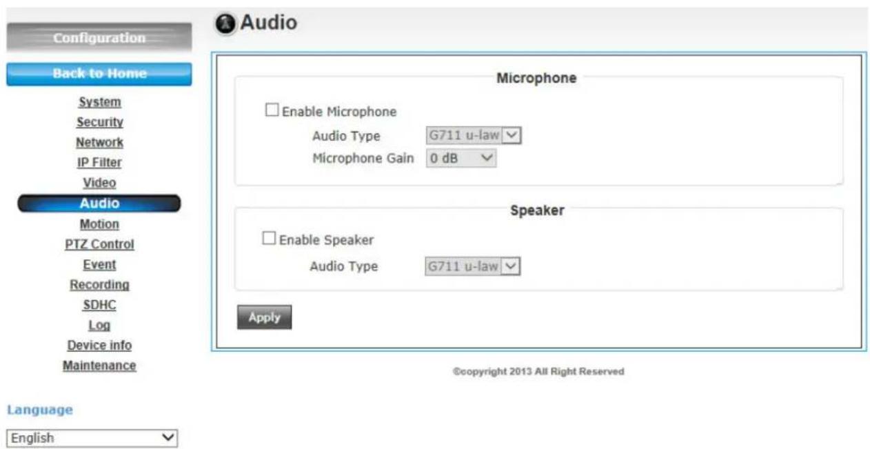
Here are the descriptions of every setup item:
| Item | Description |
| Enable Microphone | Check this box to enable microphone. If you don’t want to hear voice from IP camera, you can uncheck this box to disable it. |
| Audio Type (Microphone) | The format is fixed as G.711 |
| Microphone Gain | If the voice received by microphone is too loud or silent, you can use this function to improve voice volume, so you can hear voice from IP camera more clearly.- Select -2 or -1 dB to correct the voice that is too loud;- Select 0 dB and IP camera will do nothing on the voice;- Select +2 dB to +26 dB to amplify the voice. |
| Enable Speaker (Speaker) | Check this box to enable speaker. If you don’t want people at IP camera to hear you, you can uncheck this box to disable it. |
| Audio Type (Speaker) | The format is fixed as G.711 |
When you finish with above settings, click 'Apply' button to save changes.
6.7 Motion
This IP camera is capable to detect object's motion, so IP camera will only record when there's motion and save disk storage space.
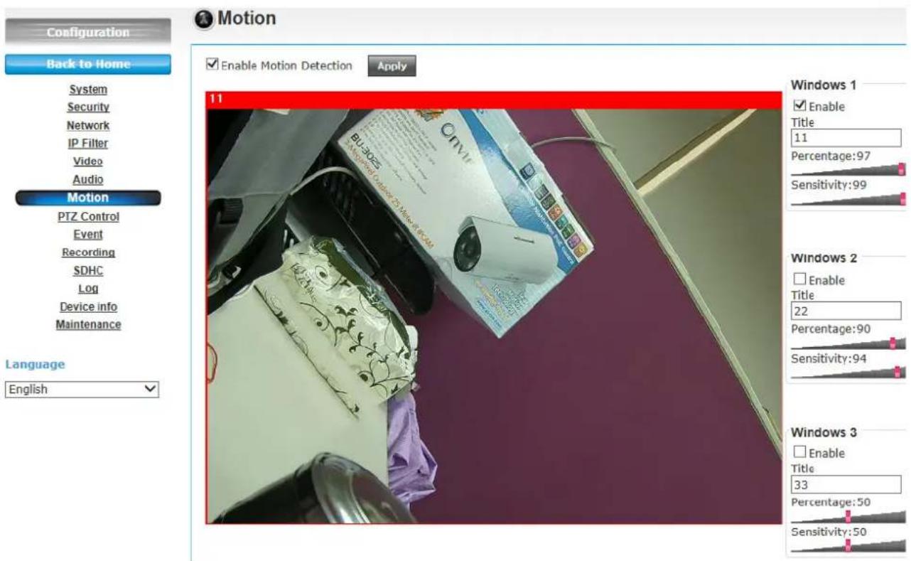
Motion detection is performed by examine the movement of objects in rectangular motion detection area. You can define up to 3 motion detection areas.
Here are the descriptions of every setup item:
| Item | Description |
| Enable Motion Detection | Check this box to enable motion detection. |
Enable (Window 1 to Window 3)  | Check this box to enable this motion detection window. You can select window 1 to 3 to enable up to 3 motion detection windows. When a motion detection window is enabled, a rectangular will appear on camera's view, with its title on the top.- To move / resize a motion detection window:- Move: Use the mouse to drag the title text.- Resize: Use the mouse the drag the four corners (upper-left/right, lower-left/right) to resize it. If you only want to adjust width or height, drag the four sidebars (top, bottom, left, and right). |
| Title (Window 1 to Window 3) | Input characters in title field to change motion detection area's title text so you can identify it.Please note that you have to click 'Apply' button and the text will change. |
| Percentage | Select the percentage of pixel change that will trigger motion detection alert. Select a lower percentage so you can detect tiny changes in motion detection area. |
| Sensitivity | Select the sensitivity level that will trigger motion detection alert. Select a higher sensitivity so you can detect tiny changes in motion detection area. It will show blue bar when window are detecting moving object through the window range. |
When you finish with above settings, click 'Apply' button to save changes. Once the window detects motion, one blue flexible bar will appear at the bottom edge. One video file will be saving at this moment if the ftp server was enabled.
6.8 PTZ Control
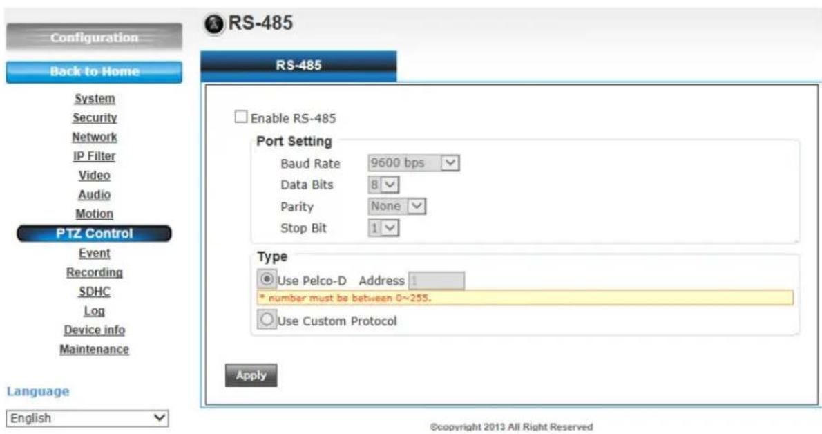
If you mount the IP camera on pan-tilt camera cradles that support pan-tilt control via RS-485 connection, you can use this function to control pan-tilt camera cradle so you can control the orientation of IP camera from remote place.
| Item | Description |
| Enable RS-485 | Check this box to enable RS-485 functionality. |
| Use Pelco-D Address | Select this option and RS-485 interface will output pan-tile control signal in Pelco-D format. This format is widely accepted by most of pan-tilt camera cradles.You have also input pan-tilt camera cradle's address code in ‘Address’ field. This code must be identical to pan-tilt camera cradle's address code. |
| Use Custom Protocol | When the pan-tilt camera cradle does not support Pelco-D protocol, you can define a protocol's detail by this function. |
When you finish with above settings, click 'Apply' button to save changes.
Please refer to pan-tilt camera cradle's user manual to define the protocol.
| Port Setting | - Baud Rate: Select data baud rate of RS-485 interface that pan-tilt camera cradle will accept. When the length of RS-485 connection is very long (longer than 200M), it's not recommended to use high speed connection (greater than 2400bps).- Data Bits: Select data bits of RS-485 connection.- Parity: Select parity bit: odd, even, or space.- Stop Bit: Select stop bit: 1 or 2. |
| Customer Commands | - Home/Up/Down/Left/Right: Input the command string used to move pan-tilt camera cradle to home or up/down/left/right position. You can click 'Test' button to send command string for testing. |
| Extended Command 1 ~ 5 | You can define extra pan-tilt camera cradle control strings here by giving it a name (Command Name) and command string (Hexadecimal Message). You can also click 'Test' button to send command string for testing. |
6.9 Event
When there's an event, you can use this setup page to define what IP camera should do, like send an Email or trigger digital output to activate external alarm.
There are three setup pages:
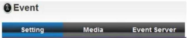
- Setting: Define a new event and manage events.
- Media: Define what kind of media file should be saved on designate media.
- Event Server: Define the details of remote server.
Please refer to following chapters for detailed instructions.
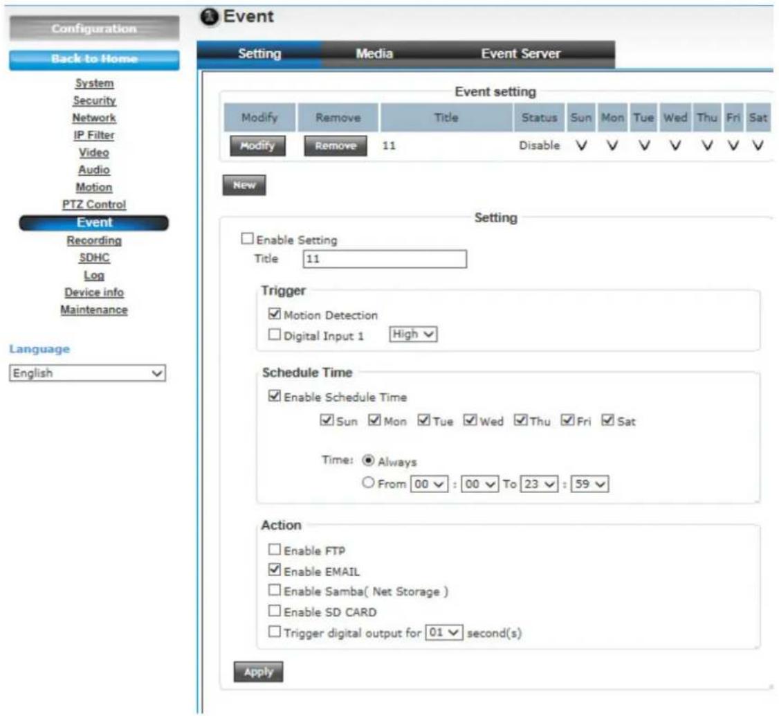
1. Setting
This page lists all existing events. You can click 'Modify' button to edit an existing event, or 'Remove' to delete an existing event.
To create a new even, just click "New" button to add an Event setting.
To add a new event, click 'New' button and the descriptions of every setup item is listed below:
| Item | Description |
| Enable Setting | Check this box to enable this event. If you just want to disable this event temporarily, you can uncheck this box to keep this event and disabling while not deleting it. |
| Title Input any description text for this event so you can identify it quickly.You can use alphabets, numbers, and symbols include: !$-.@^~ (no spaces allowed). | |
| Motion Detection | Check this box and this event will be activated when one of motion detection window detects motion. |
| Digital Input 1 | Check this box and this event will be activated when “Digital Input 1” input signal is high or low (select from dropdown list). |
| Enable Schedule Time | Check this box and this event will be activated when designated weekday and time is reached.You also have to check weekday box, and select time from dropdown list. If you select ‘Always’ as time, this event will be activated during all the day. |
| Enable FTP Check this box and IP camera will save file on FTP server (refer to ‘FTP Server’ setting in ‘Event Server’ tab) when this event is activated. | |
| Enable EMAIL | Check this box and IP camera will send an Email to designated recipient address (refer to ‘SMTP Server’ setting in ‘Event Server’ tab) when this event is activated. |
| Enable Samba (Net Storage) | Check this box and IP camera will save file on samba server (refer to ‘Samba Server’ setting in ‘Event Server’ tab) when this event is activated. |
| Enable SD CARD | Check this box and IP camera will save file on SD card when this event is activated. A working SD card must be inserted into IP camera in advance. |
| Trigger digital output for xx second(s). | Check this box and IP camera will trigger digital out to ‘high’ state for xx seconds when this event is activated, where ‘xx’ seconds must be defined by the dropdown list. |
2. Media
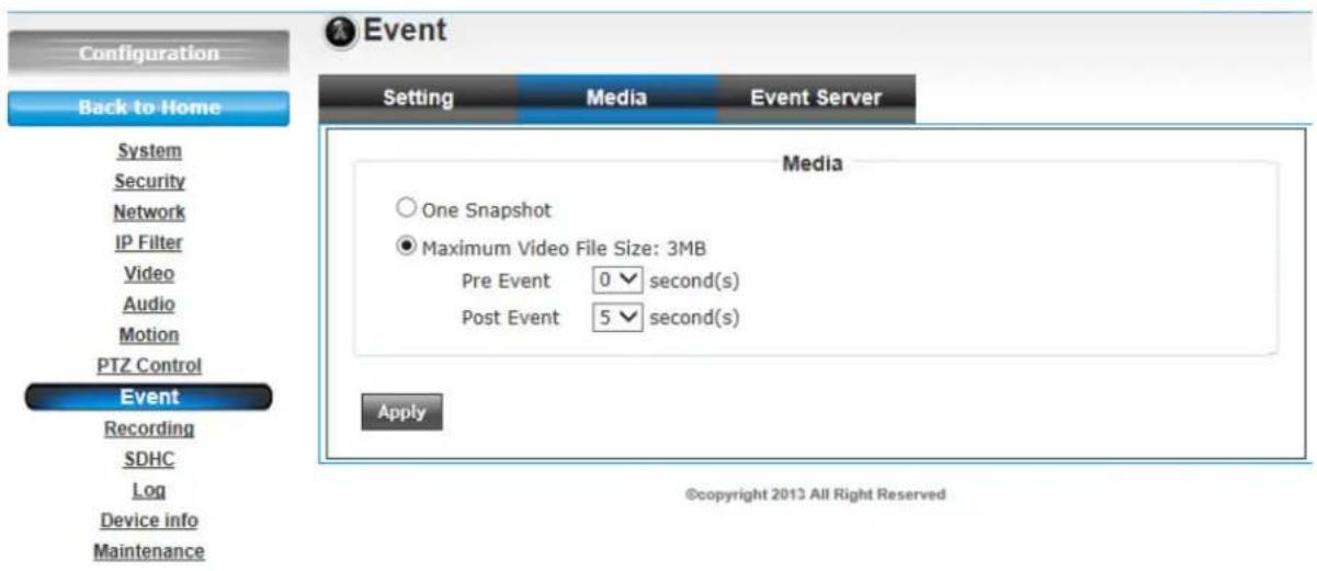
Here are the descriptions of every setup item:
| Item | Description |
| One Snapshot Save a picture file when event is triggered. | |
| H.264 Video Save a H.264 video clip. You can also select the recording length before and / or after the time when event is triggered in ‘Pre Event’ and ‘Post’ Event’.For example, if you set ‘Pre Event’ to ‘10’ and ‘Post Event’ to 5’, and an event is triggered at 14:10:30, then the video file will be 15 seconds long, starting from 14:10:20 to 14:10:35.Tips: You may want to know what happened before event is triggered in many cases, especially when object is outside of motion detection window.Note: If the “Pre Event” set to “0” second, the “Post Event” cannot set to “0” second. | |
When you finish with above settings, click 'Apply' button to save changes.
3. Event Server
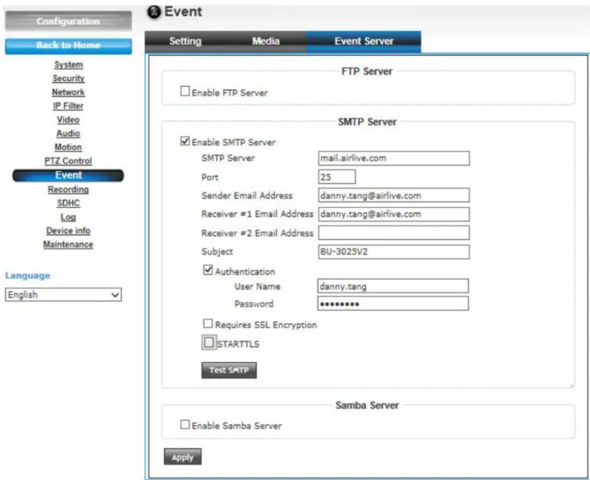
You can define the details of remote media server: FTP (File), SMTP (Email), and Samba (File).
A Samba server can be any computer running windows operating system with network neighbor function enabled. Many stand-alone network file server also support samba server function.
Here are the descriptions of every setup item:
| Item | Description |
| Enable FTP Server | Check this box to enable FTP server upload. |
| Enable FTP ServerFTP ServerPort 21User NamePasswordFile Path NameEnable Passive ModeTest FTP | |
| - FTP Server: Input FTP server's IP address or hostname.- Port: Input FTP server's port number. In most cases it should be default value '21'.- User Name: Input FTP server's username.- Password: Input FTP server's password.- File Path Name: Input the path where you want to save file on FTP server, like 'upload/record'. If you want to save file on this FTP user's home directory, you can leave this field blank.- Enable Passive Mode: Check this box to force IP camera to communicate with FTP server in passive mode (Some FTP Server may only work when you check this box, while others don't).- Test FTP: Click this button to test FTP server settings above immediately. | |
| SMTP Server Check this box to enable Email send. | |
SMTP Server
Enable SMTP Server
SMTP Server
Port
25
Sender Email Address
Receiver #1 Email Address
Receiver #2 Email Address
Subject
SIU7110
Authentication
User Name
Password
Requires SSL Encryption
STARTTLS
Test SMTP
SMTP Server: Input SMTP server's IP address or hostname.
- Port: Input SMTP server's port number. In most cases it should be default value '25'.
- Sender Email Address: Input the sender's email address that will appear in the Email send by IP camera. This will help you to identify the Email sent by this IP camera, and may help when you have anti-spam software installed (you can set this Email address to 'White List' in your anti-spam software)
- Receiver #1 Email Address: Input primary recipient's Email address. This field is required.
- Receiver #2 Email Address: Input backup recipient's Email address. This field is optional.
- Subject: Input Email title that will appear in the Email send by IP camera. This will help you to identify the Email sent by this IP camera.
- Authentication: Check this box when authentication is required by the Email server you're using. You also need to input Email server's username and password in corresponding field.
- Requires SSL Encryption: If your Email server required SSL encryption, check this box. Please note that some Email server uses different port number than standard port 25 when SSL encryption is used.
- STARTTLS: If your Email server required STARTTLS encryption,
| check this box. Please note that some Email server uses different port number than standard port 25 when STARTTLS encryption is used.- Test SMTP: Click this button to test SMTP server settings above immediately. | |
| Samba Server Check this box to enable Samba server file upload. | |
When you finish with above settings, click 'Apply' button to save changes.
6.10 Recording
When a Micro-SD card is inserted into IP camera, you can save video files on it.
Note:
Be sure that the Micro-SD Card format should be FAT32. The NTFS format cannot be supported by this camera.
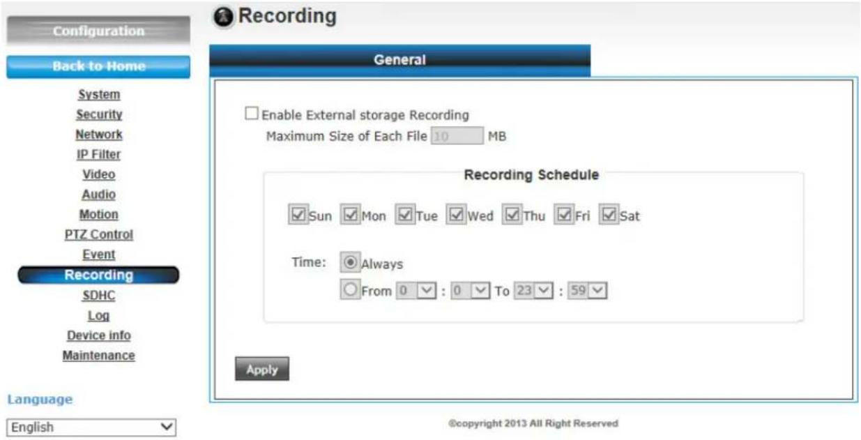
Here are the descriptions of every setup item:
| Item | Description |
| Enable External storage Recording | Check this box to record video on Micro-SD card. |
| Maximum Size of Each File | Input the maximum size of every video file from 1MB to 50MB. IP camera will start a new video file when a recording video file reaches the size limit stated here. |
Recording Schedule
Define the recording schedule. You can check Sun to Sat boxes to represent a weekday, and specify time period in 'From' and 'To' field. Select 'Always' to record 24 hours in selected weekday(s).
When you finish with above settings, click 'Apply' button to save changes.
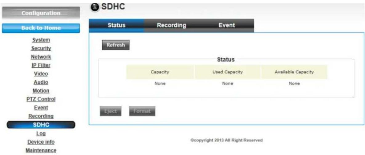
6.11 SDHC
1. Status
Once the Micro-SD card is inserted, the UI will show the capacity of the Micro-SD card like the image hereunder.
2. Recording
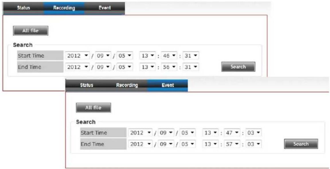
There are two UI pages to show the record on the Micro-SD card. They are mapping to the setting of “Recording to Micro-SD card” and “Event” accordingly.
Click "All file" to list all files. You also can define the range and click "Search" to sort the files needed. It shows likes the images in the next page.
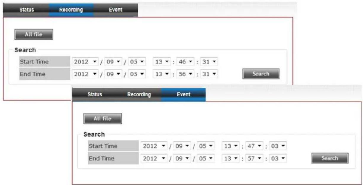
3. Event
Set the time range then click "Search" then shows the records like below.
6.12 Log
You can check the usage log of IP camera here.
In this page, you can click:
- First page / Final page: Jump to first / final page of log.
- Previous / Next: Jump to previous or next page of log.
- Remove: Clear log. You'll be prompted for confirmation.
Log
System Log
| Item | Date and Time | Event |
| 1. | 10/08/2013 22:29:16 | [SDCard]: NO Card !!! |
| 2. | 10/08/2013 22:29:13 | [SDCard]: NO Card !!! |
| 3. | 10/08/2013 22:29:10 | [SDCard]: NO Card !!! |
| 4. | 10/08/2013 22:29:06 | [SDCard]: NO Card !!! |
| 5. | 10/08/2013 22:29:03 | [SDCard]: NO Card !!! |
| 6. | 10/08/2013 22:29:00 | [SDCard]: NO Card !!! |
| 7. | 10/08/2013 22:28:57 | [SDCard]: NO Card !!! |
| 8. | 10/08/2013 22:28:53 | [SDCard]: NO Card !!! |
| 9. | 10/08/2013 22:28:50 | [SDCard]: NO Card !!! |
| 10. | 10/08/2013 22:28:47 | [SDCard]: NO Card !!! |
| 11. | 10/08/2013 22:28:44 | [SDCard]: NO Card !!! |
| 12. | 10/08/2013 22:28:40 | [SDCard]: NO Card !!! |
| 13. | 10/08/2013 22:28:37 | [SDCard]: NO Card !!! |
| 14. | 10/08/2013 22:28:34 | [SDCard]: NO Card !!! |
| 15. | 10/08/2013 22:28:31 | [SDCard]: NO Card !!! |
| 16. | 10/08/2013 22:28:27 | [SDCard]: NO Card !!! |
| 17. | 10/08/2013 22:28:24 | [SDCard]: NO Card !!! |
| 18. | 10/08/2013 22:28:21 | [SDCard]: NO Card !!! |
| 19. | 10/08/2013 22:28:18 | [SDCard]: NO Card !!! |
| 20. | 10/08/2013 22:28:14 | [SDCard]: NO Card !!! |
6.13 Device Info
You can check the information and network settings of this IP camera. This information is very useful when you need to repair or fix the problem of this IP camera.
An example of device info page looks like this:
Device info
Basic
| Camera Name | BU-3025V2 |
| Firmware version | 1.03.10 |
| MAC | d4:a4:25:00:40:64 |
| Camera Date and Time | 10/08/2013 22:30:35 |
H.264
| Video Resolution | 640x480 (VGA) |
| Video Quality | Normal |
| Frame Rate | 30 fps |
MJPEG
| Video Resolution | 640x480 (VGA) |
| Video Quality | Normal |
| Frame Rate | 30 fps |
Audio
| Microphone In | Disable |
| Microphone Gain | 0 dB |
| Speaker Out | Disable |
Mobile View
| 3GPP Enable | Disable |
Network
| IP MODE | DHCP IPv4/IPv6 |
| IP Address(IPv4) | 192.168.0.104 |
| IP Address(IPv6) | |
| Subnet Mask | 255.255.255.0 |
| Gateway | 192.168.0.254 |
| Primary DNS | 192.168.0.254 |
| Secondary DNS | 0.0.0.0 |
©copyright 2013 All Right Reserved
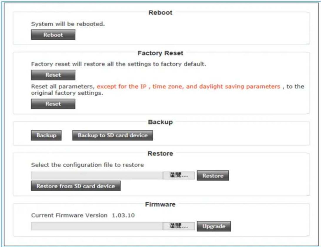
6.14 Maintenance
You can do some maintenance job about this IP camera here.
Here are the descriptions of every setup item:
| Item | Description |
| Reboot Click this | button to reboot the IP camera. This function is useful when you find IP camera is not working properly. |
| Factory Reset (1) | Clear all settings of IP camera and reset to factory default setting.(2) Reset all parameters, except for the IP , time zone, and daylight saving parameters , to the original factory settings |
| Backup Backup IP camera's setting and save it on your computer. | |
| Backup to SD card device | Backup IP camera's setting and save it on SD card. A SD card must be inserted into SD card slot when you click this button, or you'll receive an error message. |
| Restore | Restore a previously-saved configuration file savedClick ‘Browse’ button to select a file on your computer first, then click ‘Restore’ button. |
| Restore from SD card device | Restore IP camera's configuration which is previously-saved on SD card. |
| Upgrade Upgrade | IP camera's firmware. Click ‘Browse’ button to select a firmware image file on your computer first, then click ‘Upgrade’ button. |
on your c
Maintenance
7
Appendix
A. Digital I/O User Guide
DI/DO connector – Use in applications for e.g. motion detection, event triggering, Micro-SD recording and alarm notifications via FTP/EMAIL/SAMBA.
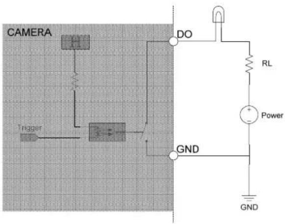
- Digital output — for connecting external devices such as relays, alarm bell or LEDs. Connected devices can be activated by the Configuration→Event interface or digital output buttons on the Home page.
| Pin | Notes | Specifications |
| Trigger is “Off”, DO connect to GNDTrigger is “On”, DO is floating | Max load: 30mA,30VDC |
Please refer to the following illustration for DO connection method
- Digital input — An alarm input for connecting devices that can toggle between an open and closed circuit, for example: PIRs, door/window contacts, glass break detectors, etc. When a signal is received the state changes and the input becomes active.
| Pin Notes Specifications | |
| DI is floating, trigger is “high”DI is high, trigger is “low” | Max current input: 30mA |
Please refer to the following illustration for DI connection method
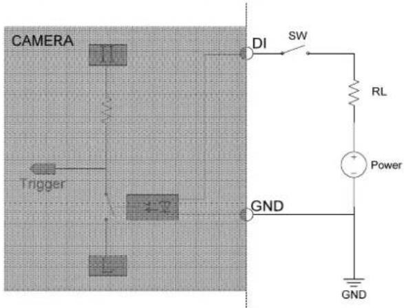
Suggested Component Value
| Power(VDC) RL(Ω) | |
| 3.3V | 100Ω |
| 5V | 200Ω |
| 12V | 510Ω |
- Powered by OvisLink Corp.
- Copyright & Disclaimer
- FCC Statement
- Federal Communication Commission Interference Statement
- FCC Caution
- FCC Radiation Exposure Statement
- Table of Contents
- Overview....1
- Package Contents and Installation....6
- Using IP Camera via Web Browser....12
- Operating IP Camera via Mobile Phone 14
- Operating the Network Camera ....17
- Configuration ......21
- Appendix....51
- 1
- Overview
- Introduction
- Features
- System Requirement
- 2
- Package Contents and Installation
- Package Content
- Connections
- Power Source Requirement
- Switch/Connector
- Mounting the Camera
- Plug an Ethernet cable into the Camera
- Connect the external power supply to Camera
- Connect to IP Camera
- 3
- Using IP Camera via Web Browser
- Windows Web Browser
- 4
- Operating IP Camera via Mobile Phone
- Using IP Camera via iPhone
- Click Add button.
- Click LAN button and select the camera.
- 5
- Operating the Network Camera
- Live View
- Language
- Stream
- Protocol
- Digital Output
- 2-Way Audio
- Volume
- Original size / Preview Size
- Digital Zoom
- Snapshot
- Record
- Recording Location
- Configuration
- 6
- Configuration
- System
- System
- - Host Name
- - Indicator LED
- Date and Time
- - Time Zone
- - Daylight Saving
- - Synchronize with computer time
- - Synchronize with NTP Server
- - Set Manually
- Security
- - Administrator
- - User
- - Guest
- Network
- General
- - PPPoE:
- - HTTP Port:
- - RTSP Port:
- - RTP Data Port:
- Advanced
- - DDNS:
- • DIPS ID:
- - HTTPS:
- IP Filter
- Video
- Image Setting
- • TV Out:
- - IR cut:
- • Day:
- Video Setting
- Overlay
- Video
- Audio
- Motion
- PTZ Control
- Event
- Setting
- Media
- Event Server
- SMTP Server
- Recording
- Note:
- SDHC
- Status
- Recording
- Event
- Log
- Log
- Device Info
- Device info
- Maintenance
- Maintenance
- 7
- Appendix
- Digital I/O User Guide
Brand : AIRLIVE
Model : BU-3025
Category : Security Camera