
BU-3026 - Security Camera AIRLIVE - Free user manual and instructions
Find the device manual for free BU-3026 AIRLIVE in PDF.


| Product Type | Security Camera |
| Brand | AirLive |
| Model | BU-3026 |
| Resolution | 1920x1080 (Full HD) |
| Lens | 2.8mm fixed |
| Field of View | 90° |
| Night Vision | IR LEDs up to 30m |
| Video Compression | H.264/H.265 |
| Network | Ethernet (10/100), Wi-Fi 802.11 b/g/n |
| Power | DC 12V / PoE (802.3af) |
| Dimensions | 150 x 70 x 70 mm |
| Weight | 350g |
| Operating Temperature | -10°C to 50°C |
| Storage | MicroSD card up to 128GB |
| Audio | Built-in microphone and speaker |
| Motion Detection | Yes, with email alerts |
| Weatherproof | IP66 |
| Mounting | Wall/ceiling mount included |
| Accessories Included | Power adapter, mounting kit, quick guide |
| Maintenance & Cleaning | Clean lens with soft cloth; avoid chemical cleaners. Keep vents unobstructed. |
| Security | Use strong password, enable encryption, update firmware regularly |
| Spare Parts & Repairability | Contact AirLive support for replacement parts; design allows for basic component replacement |
Frequently Asked Questions - BU-3026 AIRLIVE
User questions about BU-3026 AIRLIVE
0 question about this device. Answer the ones you know or ask your own.
Ask a new question about this device
Download the instructions for your Security Camera in PDF format for free! Find your manual BU-3026 - AIRLIVE and take your electronic device back in hand. On this page are published all the documents necessary for the use of your device. BU-3026 by AIRLIVE.
USER MANUAL BU-3026 AIRLIVE
natural_image
Group photo of four smiling young people in a modern office setting (no visible text or symbols)Air Live®
Powered by OvisLink Corp.
Copyright & Disclaimer
No part of this publication may be reproduced in any form or by any means, whether electronic, mechanical, photocopying, or recording without the written consent of OvisLink Corp.
OvisLink Corp. has made the best effort to ensure the accuracy of the information in this user's guide. However, we are not liable for the inaccuracies or errors in this guide. Please use with caution. All information is subject to change without notice
This product contains some codes from GPL. In compliance with GPL agreement, AirLive will publish the GPL codes on our website. Please go to www.airlive.com and go to the "Support->GPL" menu to download source code.
All Trademarks are properties of their respective holders.
FCC Statement
Federal Communication Commission Interference Statement
This equipment has been tested and found to comply with the limits for a Class B digital device, pursuant to Part 15 of the FCC Rules. These limits are designed to provide reasonable protection against harmful interference in a residential installation. This equipment generates uses and can radiate radio frequency energy and, if not installed and used in accordance with the instructions, may cause harmful interference to radio communications. However, there is no guarantee that interference will not occur in a particular installation. If this equipment does cause harmful interference to radio or television reception, which can be determined by turning the equipment off and on, the A user is encouraged to try to correct the interference by one of the following measures:
■ Reorient or relocate the receiving antenna.
■ Increase the separation between the equipment and receiver.
■ Connect the equipment into an outlet on a circuit different from that to which the receiver is connected.
■ Consult the dealer or an experienced radio/TV technician for help.
FCC Caution
Any changes or modifications not expressly approved by the party responsible for compliance could void the user's authority to operate this equipment. This device complies with Part 15 of the FCC Rules. Operation is subject to the following two conditions: (1) This device may not cause harmful interference, and (2) this device must accept any interference received, including interference that may cause undesired operation. For product available in the USA/Canada market, only channel 1\~11 can be operated.
Selection of other channels is not possible.
This device and its antenna(s) must not be co-located or operation in conjunction with any other antenna or transmitter.
FCC Radiation Exposure Statement
This equipment complies with FCC radiation exposure limits set forth for an uncontrolled environment. This equipment should be installed and operated with minimum distance 20cm between the radiator & your body.
WEEE Marking Warning:
The crossed out wheeled bin indicates the product must not be disposed together with household waste. For the sake of the environment, the product should only be given to entities involved in the reception of waste electronic and electrical equipment. The lists of entities entitled to receive used equipment can be found on the websites of municipalities. Some components of devices such as external wiring, circuit boards and liquid crystal displays have a negative impact on the environment.

Bluetooth®
© 2009 OvisLink Corporation, All Rights Reserved
Table of Contents
1. Overview....1
1.1 Introduction....1
1.2 Features....2
1.3 Product Specification ....2
1.4 System Requirement ....6
2. Package Contents and Installation....7
2.1 Package Contents....7
2.2 Connections....7
2.3 Connect to IP Camera ....10
3. Using IP Camera via Web Browser....12
3.1 Windows Web Browser....12
4. Operating IP Camera via iOS/Android Device....13
4.1 Using IP Camera via iOS/Android device ....13
5. Operating the Network Camera ....16
5.1 Live View....16
5.2 Configuration ....18
6. Configuration ....19
6.1 Network....20
6.2 Video....27
6.3 Audio....34
6.4 Event......35
6.5 Storage 42
6.6 RS-485....43
6.7 System....45
6.8 Status....51
7. Appendix....53
A. Video Analytics (Only for BU-3026-IVS)....53
1
Overview
natural_image
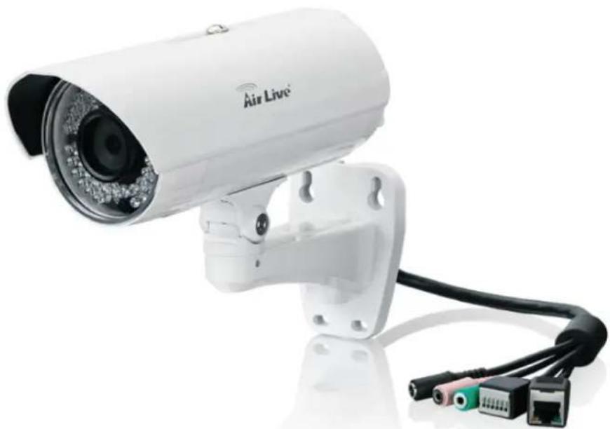
White Air Live security camera with attached network interface (no visible text or symbols on device body)This user's manual explains how to operate this camera from a computer. A user should read this manual completely and carefully before you operate the device.
1.1 Introduction
AirLive BU-3026/BU-3026-IVS is a high-end 3.0 Megapixels network camera which is designed for outdoor surveillance and security applications. This 3.0MP IP camera offers many improvements in image quality when comparing to conventional surveillance cameras. Users are able to view live video streaming over the Internet, and it is not only one of benefits for using AirLive BU-3026/BU-3026-IVS IP cameras. It is also designed to offer high-performance surveillance by being equipped with PoE switch which allows power and data to be transmitted via a single Ethernet cable. This useful function provides an easier installation, lower cabling costs and allows placement of AirLive PoE cameras in locations without access to electrical source. With the IP66 waterproof housing and cable through bracket, AirLive BU-3026/BU-3026-IVS suits for outdoor environments such as parking lot, backyard, campus and loading deck.
1.2 Features
This manual will illustrate the steps of how to setup and operate this IP camera, so you'll also soon be enjoying the benefits of these product features:
☐ IP-66 Protection with Cable through Bracket.
☐ 3.0 Megapixel 1/2.5" CMOS Sensor
☐ Support 25FPS at 2048x1536 or 30FPS at 1080P
802.3af PoE
☐ 2.6mm Wide Angle CS Mount Lens
☐ Low Lux Sensor for Ultra Bright Images
25m IR LEDs
□ Mechanical IR-Cut Filter Removable
□ MicroSD Card Slot for Local Storage
☐ Two-Way Audio, DI/DO
☐ Clear Motion Technology for Moving Objects
□ WDR Enhanced
□ Compatible with ONVIF Standard
☐ Built-in Video Analytics (Equipped only for BU-3026-IVS)
☐ Free 64-Channel Recording Software
1.3 Product Specification
| Model BU-3026/BU-3026-IVS | ||
| Camera | Camera Type Bullet | Type |
| Max Resolution 2048x1536 | ||
| Image Sensor 1/2.5" | CMOS Sensor | |
| Lens Type | CS Mount Lens | |
| 2.6mm, F1.2 | ||
| Night Vision Yes | ||
| IR Distance 25m | ||
| Minimum Illumination 0.2 Lux at F1.2 (Color) | ||
| Mechanical IR-Cut Filter Yes | ||
| Auto Iris None | ||
| Viewing Angle | 160 °(D),105 °(H),72 °(V) | |
| Pan/Tile Control | Lens Adjustment: Pan: 0~350° Lens Adjustment: Tilt: 53~106° | |
| Analog Video Out None | ||
| Video | Video Compression | H.264MPEG-4MJPEG |
| Video Profile Yes | ||
| Resolution and Frame Rate | 25 fps @ 2048 X 1536 | |
| 30 fps @ 1920 X 1080 | ||
| 30 fps @ 1280 x 1024 | ||
| 30 fps @ 1280 X 960 | ||
| 30 fps @ 1280 X 720 | ||
| 30 fps @ 720 X 480 | ||
| 30 fps @ 640 X 480 | ||
| 30 fps @ 320 X 240 | ||
| 30fps @ 160 X 120 | ||
| Streaming | Streaming over UDP, TCP, or HTTP | |
| 3GPP mobile view | ||
| Configurable frame rate and bandwidth | ||
| Support both CBR and VBR | ||
| Region of Interest Yes | ||
| Image Processing | AE, BLC, AW | |
| Brightness, Sharpness, Contrast, Saturation | ||
| Mirror/Flip | ||
| Privacy Masks | ||
| Text, time and date OSD | ||
| Digital Zoom 10x | ||
| Audio | Audio Encoder G.711 / AMR (Only for 3GPP) | |
| Audio Streaming Two-way | ||
| Audio Input/Output 1 Line in, 1 Line out | ||
| Network | Ethernet | Ethernet (10/100 Base-T), RJ-45 |
| PoE | IEEE802.3af | |
| Wireless | None | |
| Supported Protocols | TCP/IP, IPV6, UDP, ICMP, DHCP, NTP, DNS, DDNS, SMTP, FTP, HTTP, HTTPS, Samba, PPPoE, UPnP, Bonjour, RTP, RTSP, RTCP, DLNA, ISCSI, ONVIF 2.2 | |
| Security | Password protection | |
| IP filter, HTTPS encrypted data transmission | ||
| Users Up to 10 users simultaneous | ||
| LED and Button | Power LED Yellow Color | |
| Link/Act. LED Orange Color | ||
| Reset Button | Reset to Factory Default (Push and Hold Over 5 Sec) | |
| General | Network Processor DSP Base | |
| System ROM 128M byte NAND Flash | ||
| System RAM 128M byte DDR SDRAM | ||
| Power Supply DC 12V/1.08A | ||
| Power Consumption | IR on: 8 Watts max., IR off: 5 Watts max. | |
| Connector | RJ-45 10BaseT/100BaseTX | |
| Audio and Mic jack, DI/DO, DC jack, Ethernet/PoE | ||
| Operating temperature and humidity | -20°C~55°C (-4°F~131°F), 20%~85% | |
| SD card slot MicroSD | ||
| Dimension 84 mm | x 82mm x 193 mm | |
| System Integration | CamPro Express 64, CamPro Professional Software | |
| Search & Installation-IP Wizard II | ||
| Event Triggers | BU-3026: Motion detection, External input via DI interface, Tamper detection. BU-3026-IVS: Motion Detection, External input via DI interface, Tamper detection, Face Detection, iMotion Detection, Trip Zone, Object Counting, Face recognition, e-Fence. | |
| Motion Detection 3 | ||
| Event handler | FTP, Samba Server, SD card file upload | |
| E-mail alter | ||
| HTTP and TCP notification | ||
| DO (digital output) alarm | ||
| Audio File Playback | ||
| UPnP | Yes | |
| Application Programming Interface | ONVIF 2.2 | |
| Open API for software integration | ||
| SDK | ||
| Video Buffer Pre- and post- alarm buffering | ||
| Alarm Triggers | BU-3026: Motion Detection, External input via DI interface, Tamper detection BU-3026-IVS: Motion Detection, External input via DI interface, Tamper detection, Face detection, iMotion detection, Trip zone, Object counting, Face recognition, e-Fence. | |
| Continuous recording Yes | ||
| Viewing System | OS Windows® | XP, Vista, 7, 8 |
| Browser | Internet Explorer 7 or later; Apple Safari 2 or above; Firefox 2.00 or above; Google Chrome | |
| iOS/Android Device | With 3GPP player, CamPro Mobile for iOS/Android device | |
| Video Player | VLC, Quick Time, Real Player, Core Player | |
1.4 System Requirement
For normal operation and viewing of the network camera, it's recommended that your system meets these minimum requirements for proper operation:
| Item | Requirements |
| CPU Pentium-4 2.0 GHz | or higher |
| VGA Monitor Resolution1 | 024 x 768 or higher |
| RAM 1 GB or more | |
| Operating System Windows XP, Vista, 7, 8 | |
| Web Browser | Internet Explorer 7 or later; Apple Safari 2 or above; Firefox 2.00 or above; Google Chrome |
Note: Please keep updating the latest Windows software and service package.
(Ex: Net Framework, Windows Media Player, Enhance ActiveX Security)
2
Package Contents and Installation
2.1 Package Contents
User can find the following items in the package as below:
- AirLive BU-3026/BU-3026-IVS is the main element of the product.
- Bundled CD includes AirLive IP Wizard II, CamPro Express64, Quick Start Guide, User Manual, and Video clip.
- Quick Start Guide provides important information and instructions for installing this device.
- Accessory Package (Screws / Plastic Anchors/ DIDO Adapter/ Power Adapter)
2.2 Connections
Power Source Requirement
This camera can work with 802.3af PoE switches. However, if you don't have the PoE switch, you can use a power adapter to provide power to camera.
Connector
There are various connectors of AirLive BU-3026/BU-3026-IVS as shown in the figures below. Please refer to the diagrams and tables for using of each connector.
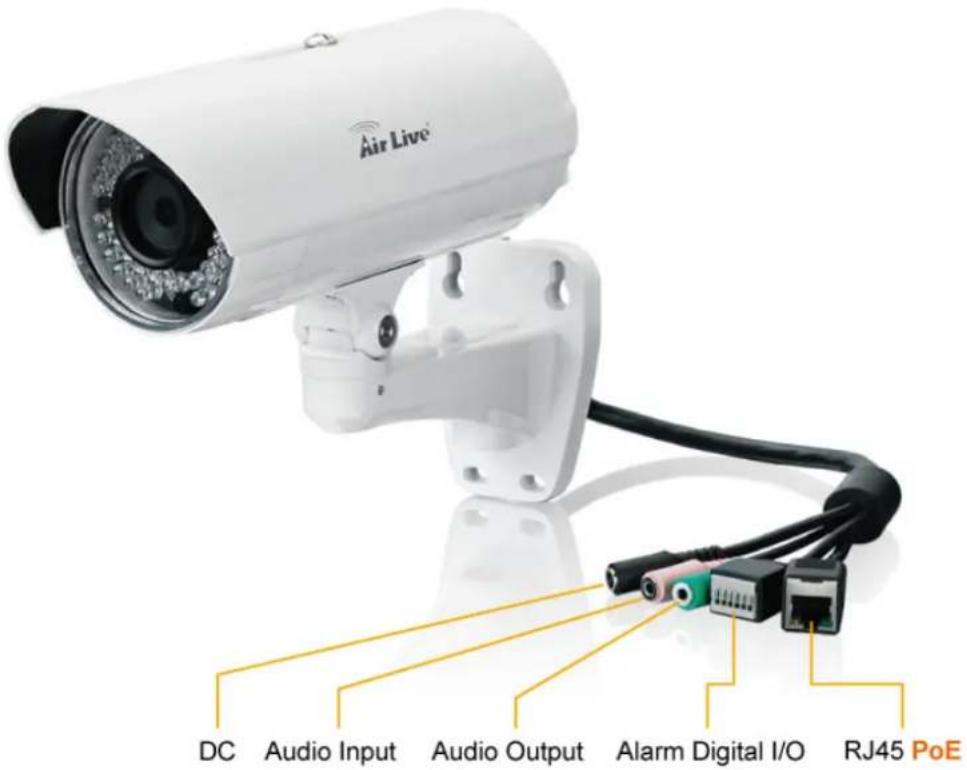
- DC Jack: The input power is DC 12V.
If you don't have the PoE switch, you can use a power adapter to provide power to camera.
- PoE/RJ45 LAN Socket: Connect to PC or Hub/Switch.
This Ethernet port built N-Way protocol can detect or negotiate the transmission speed of the network automatically. Please use Category 5 cable to connect the Network Camera to a 100Mbps Fast Ethernet network switch or hub.
- Alarm Digital I/O:
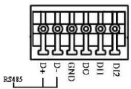
AirLive BU-3026/BU-3026-IVS supports RS-485, 2 digital alarm inputs and 1 digital alarm output. Please make sure the alarm connections are properly wired. Please refer to the pin definition table below.
| PIN SPECIFICATION | ||
| 1 | RS-485 D+ | Compliant to RS-485 |
| 2 | RS-485 D- | |
| 3 | Ground (Common) GND | |
| 4 | GPIO Out | Close circuit current maximum: 70mA AC or 100mA Output resistance: 30 ohm Open circuit voltage maximum: 240V AC or 350V DC |
| 5 | GPIO In #1 | Action high voltage: 9~40 VDC Dropout voltage: 0 VDC |
| 6 | GPIO In #2 | |
- Audio Output: 3.5mm phone jack.
- Audio Input: 3.5mm MIC jack.
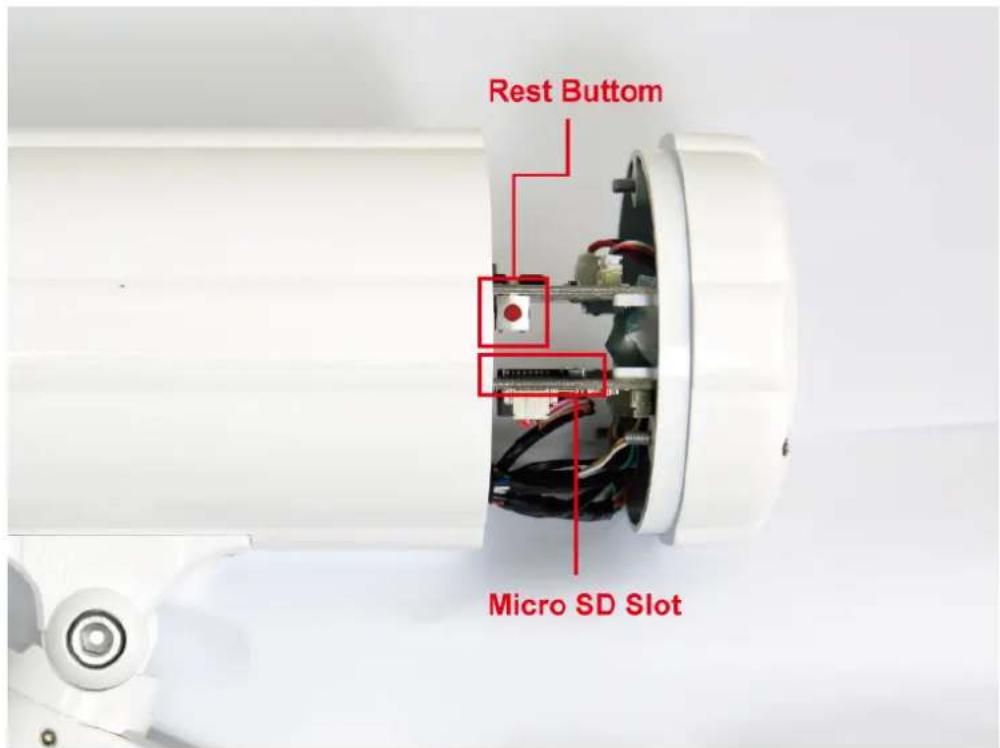
- MicroSD Card Slot: MicroSD Card Slot allows you to insert a memory card for expansion of storage.
- Reset Button: This button is used to restore all the factory default settings. Sometimes, restarting the device will make the system back to a normal state.
2.3 Connect to IP Camera
- Insert the bundled CD into your PC/Laptop.
- Auto Run screen shows up, click "Install Software → AirLive IP Wizard II" to install the configuration tool.
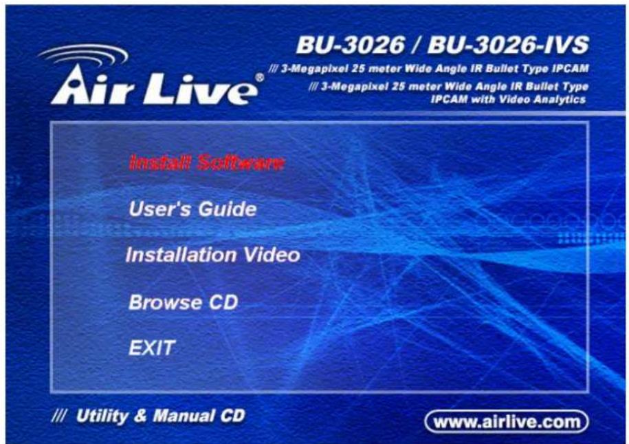
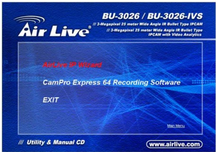
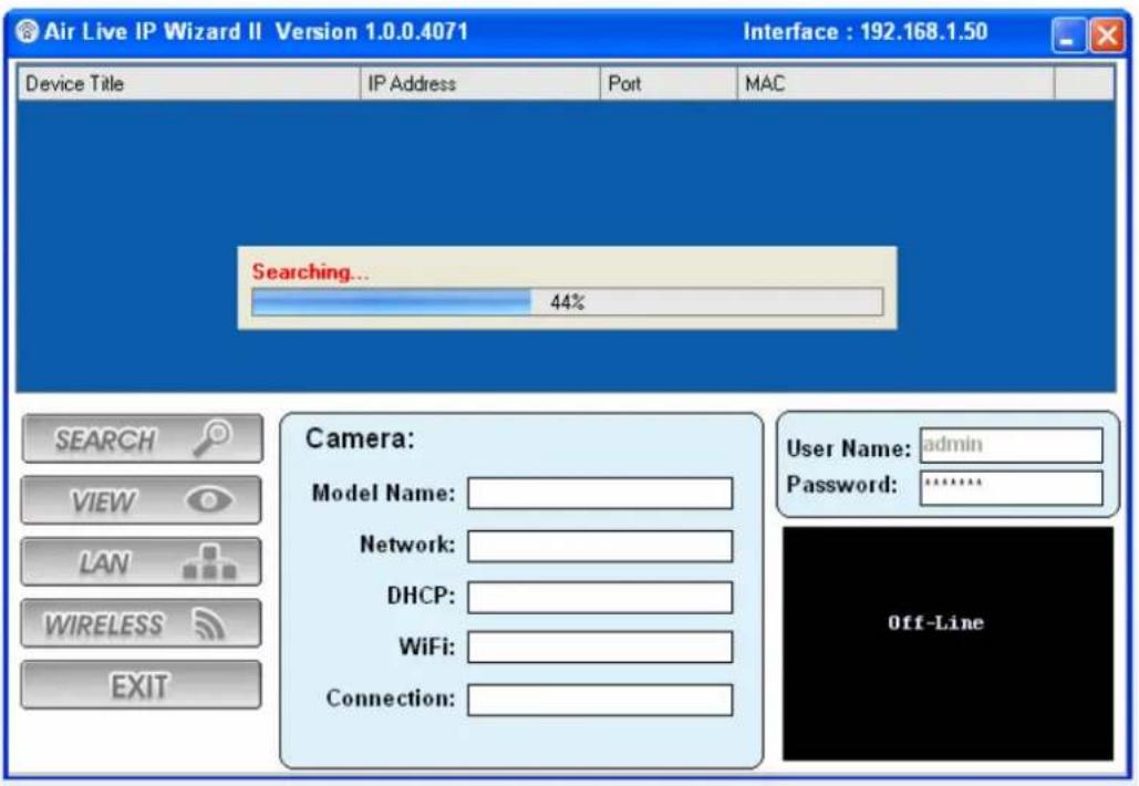
- After completed the installation, run the "Air Live IP Wizard II" to start to search the IP camera.
- The entire detected IP camera will be listed out.
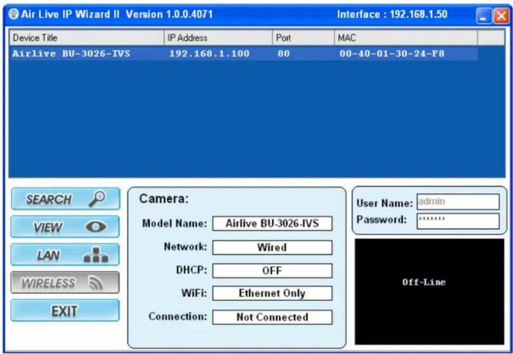
- If the Camera's IP address is in the same IP segment as your LAN, select the founded IP Camera and double click on the item. Then, the default browser will show up and connect to the IP camera's Web automatically.
3
Using IP Camera via Web Browser
3.1 Windows Web Browser
- Open your web browser and enter the IP address or host name of the IP camera in the Location / Address field of your browser.
- Use the default account "admin" and default password "airlive".
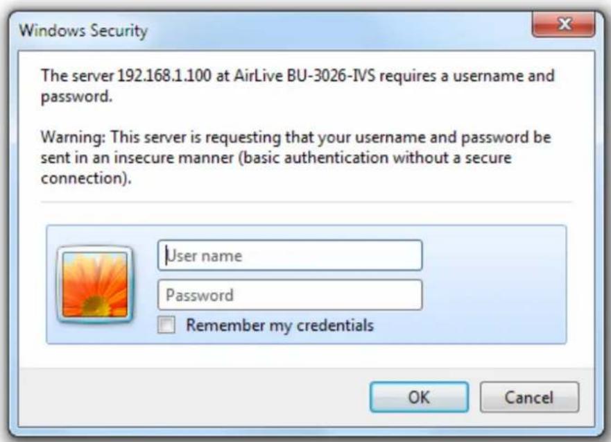
Note: The default user name "admin" and the password "airlive" are the default values. You can change them in the Account Menu. (Please check "System → Account")
- The monitor image will be displayed in your browser. In the left side of main window, you can configure the settings you want. For more details, please refer to the following chapters.
4
Operating IP Camera via iOS/Android Device
4.1 Using IP Camera via iOS/Android device
You can access into your IP camera via the iOS/Android device. Please follow the setup steps below.
- Download AirLive CamPro Mobile from APP store/Android market.
natural_image
Blue square icon with white camera lens and circular motion lines, plus Air Live® logo below (no text beyond logo design)- Execute the AirLive CamPro Mobile program
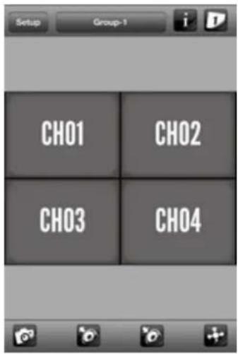
- Click Setup button.
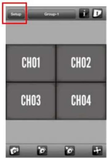
- Setup page appears

5. Click Add button
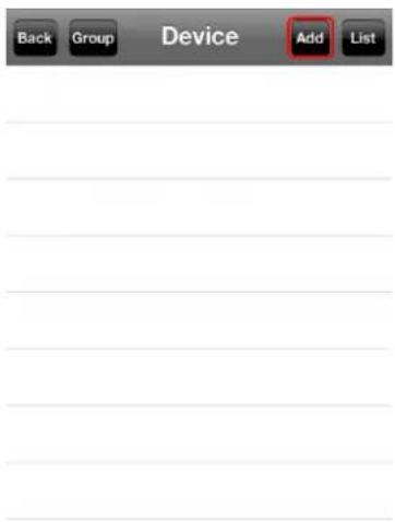
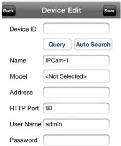
6. Click Auto Search button and select the camera.
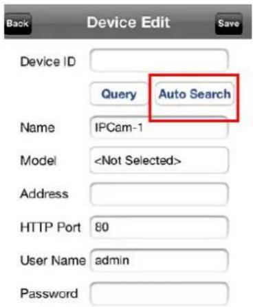
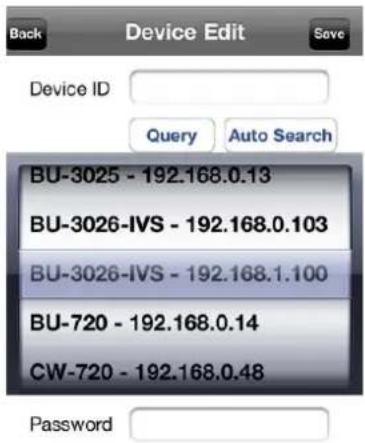
- Model, Address, HTTP Port info appear on the page.
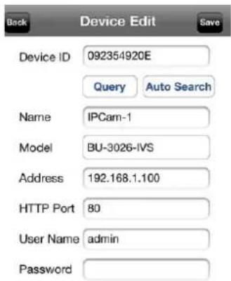
- Key-in Username and Password then click Save button.
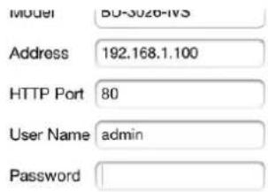
- If camera connects correctly, it will show blue icon.
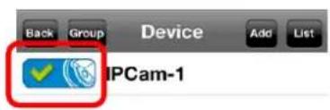
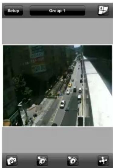
- The video appears on the main screen.
natural_image
Street view from a mobile app interface showing a multi-lane highway with vehicles and buildings in the background (no readable text or symbols)Note: The image is continuous snapshots, not video. Thus, live image can't be recorded here.
5
Operating the Network Camera
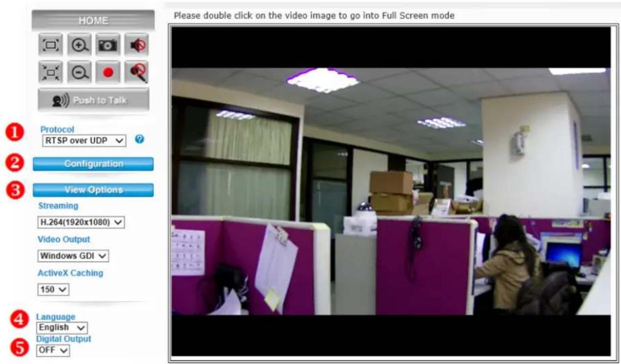
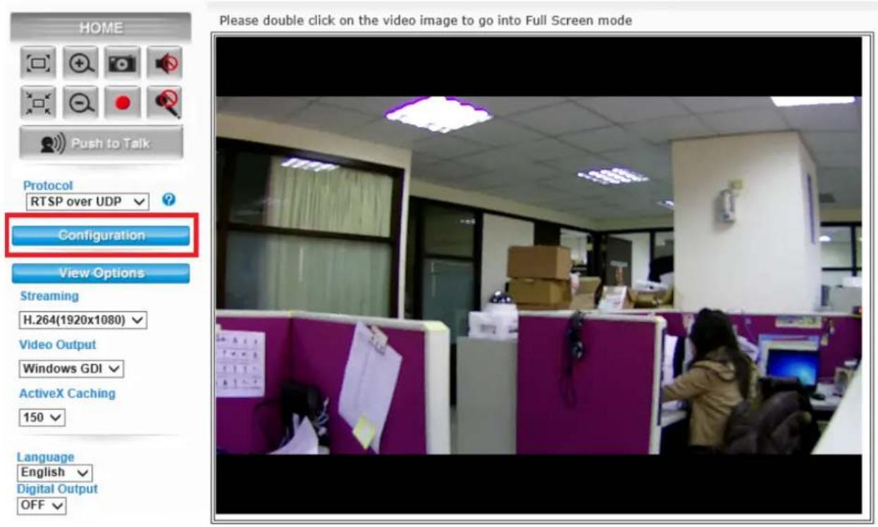
Start-up screen will be shown once you access into the IP camera. In the left side, you can control Live View function as below:
5.1 Live View
- Protocol: Select the protocol type:
RTSP over UDP/ TCP/ RTSP over TCP/ RTSP over HTTP. - Configuration: Click for configuring the detail camera settings.
- View Options: The device supports multi-profile function for H.264, MPEG4 and JPEG simultaneously. User can choose the proper and/or preferred profile which is listed here.
- Language: AirLive BU-3026/BU-3026-IVS provide multiple languages to meet customer's requirement.
-
Digital Output: Switch digital output interface on or off.
-
2-Way Audio: The device supports 2-way audio function. User can choose to enable or disable this function by toggling the icon below.
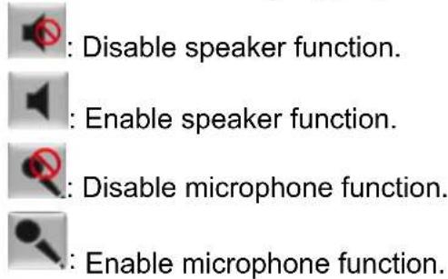
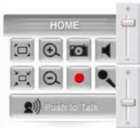
Volume: Click Speaker/Microphone button to activate this function. Scroll the control bars to adjust the audio attribute.
-
Original Size / Preview Size: Switches live image view between original size and preview size (smaller size).
-
☐ ☐ ☐ Digital Zoom: From 1X to 10X. Click ☐ to full screen first.
Click to enable this function. Click to disable it.
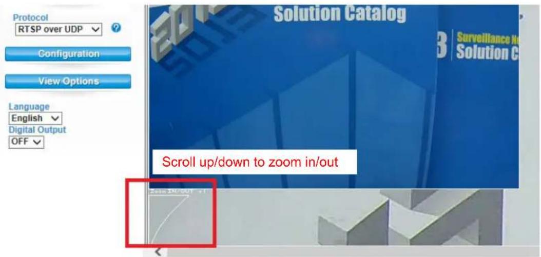
Note: Digital zoom uses computer algorithm to enlarge the video and may lose some details.
-
Snapshot: Take a snapshot or a video file. Browse the folder in your computer and save the file.
-
Record: Click it to start recording an AVI file in local storage. Press ■ to stop the recording process.
5.2 Configuration
Click "Configuration" for the camera detail settings. For more information, please refer to Chapter 6.
6
Configuration
Click the "Configuration" to display sub-menus included
Network / Video / Audio / Event / Storage / RS-485 / System / Status / Video Analytics.
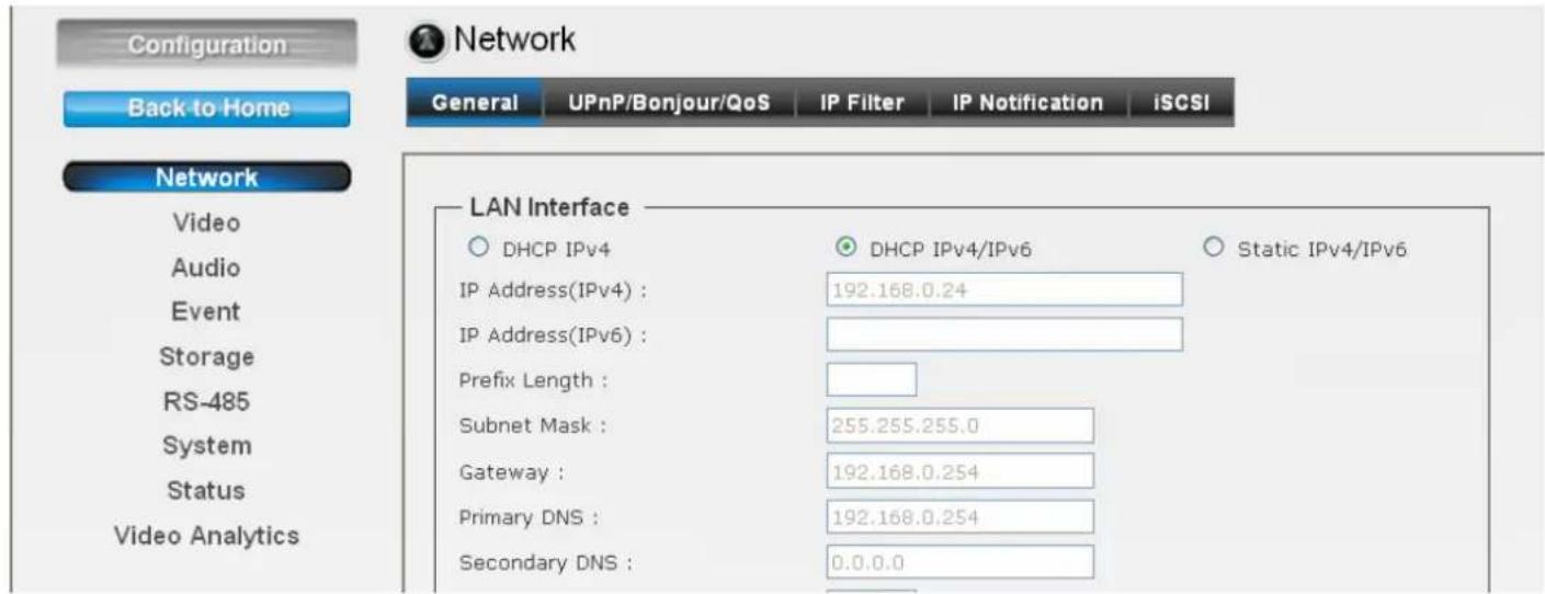
Note: Video Analytics function is only for BU-3026-IVS.
6.1 Network
1. General
Network
General UPnP/Bonjour/QoS IP Filter IP Notification iSCSI
LAN Interface
bar
| Category | DHCP IPv4 | Static IPv4/IPv6 | | :--- | :--- | :--- | | IP Address(IPv4) : | 192.168.0.73 | | | IP Address(IPv6) : | | 192.168.0.73 | | Prefix Length : | | | | Subnet Mask : | 255.255.255.0 | | | Gateway : | 192.168.0.254 | | | Primary DNS : | 192.168.0.254 | | | Secondary DNS : | 0.0.0.0 | | | HTTP Port : | 80 | | | RTSP Port : | 554 | | | RTSP over HTTP Tunnel Port : | 8554 | | | RTP Data Port : | 5556 | |Multicast
![Enable Multicast Multicast Group Address : 239.128.1.99 Multicast Video Port : 5560 Multicast RTCP Video Port : 5561 Multicast Audio Port : 5562 Multicast RTCP Audio Port : 5563 Multicast TTL[1~255] : 15](/content/2026/06/1202485/images/4c0b5a834f489dee326944f6f479a3a22066ef8c5cfa304c34f5be164ddd0c24.jpg)
PPPoE

DDNS
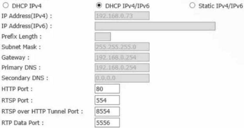
● LAN Interface: This field allows you to setup the IP network protocol.
- DHCP IPv4: Select this option when your network uses the DHCP server. When the camera starts up, it will be assigned an IP address from the DHCP server automatically.
- DHCP IPv4/IPv6: DHCP for IPv6 enables the DHCP server to pass the configuration parameters (e.g. the IPv6 network addressed) to the IPv6 nodes, which offers the capability of automatic allocation of reusable network addresses and additional configuration flexibility. Select this option if your network supports DHCP IPv6 protocol. When the camera starts up, it will be assigned an IP address from the DHCP server automatically.
- Static IPv4/IPv6: Select this option to assign the IP address to the camera directly. You can use "AirLive IP Wizard II" to obtain the related setting values.
| IP Address (IPv4/IPv6) | Enter the IP address of the camera. The default setting is 192.168.1.100. |
| Subnet Mask | Enter the Subnet Mask of the camera. The default setting is 255.255.255.0. |
| Default Gateway | Enter the Default Gateway of the camera. The default setting is 192.168.1.254. |
| Primary/ Secondary DNS | DNS (Domain Name System) translates domain names into IP addresses. Enter the Primary and Secondary DNS provided by ISP. |
| HTTP Port | The default HTTP port is 80. |
| RTSP Port | The default RTSP Port (Real Time Streaming Protocol) is 554. |
| RTP Data Port | RTP (Real-time Transport Protocol) is a data transfer protocol defined to deliver live media to the clients at the same time, which defines the transmission of video and audio files in real time for Internet applications. The default RTP Data Port is 5556. |
- Enable Multicast: Select this option to enable the multicast function of the camera. Complete the following settings so that you can deliver information from your camera to multi receivers.
- Multicast Group Address: Assign a category of IP addresses to receive the information from the camera.
- Multicast Video Port: Assign a multicast port for video in the text box. The default port is 5560.
- Multicast RTCP Video Port: Assign a multicast port for RTCP (real-time transport control protocol) video in the text box. The default port is 5561.
- Multicast Audio Port: Assign a multicast port for audio in the text box. The default port is 5562.
- Multicast RTCP Audio Port: Assign a multicast port for RTCP (real-time transport control protocol) audio in the text box. The default port is 5563.
- Multicast TTL: Set the value from 1 to 255. TTL (time to live) is used to specify the time to live in the IP header so that the system is able to decide whether or not the packet has been in the network too long and should be discarded.
- Enable PPPoE: Select this option when you use a direct connection via the ADSL modem. You need the User Name and Password of the PPPoE account to complete the setting. The camera will get an IP address from the ISP as starting up.
Note: Once the camera get an IP address from the ISP as starting up, it automatically sends a notification email to you. Therefore, when you select PPPoE as your connecting type, you have to set up the email or DDNS configuration in advance.
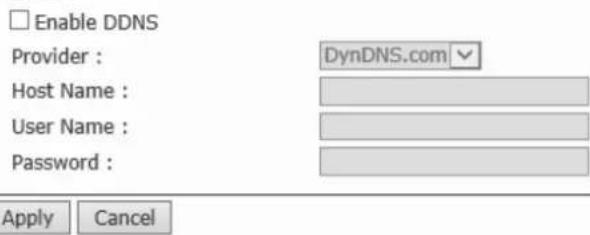
- Enable DDNS: Select this option to enable DDNS service. With the Dynamic DNS feature, you can assign a fixed host and domain name to a dynamic Internet IP address. To set up the DDNS, select the Provider from the pull-down menu and then enter the required information in the Host Name, User Name and Password text boxes.
Note: You have to sign up for DDNS service with the service provider before configuring this feature.
2. UPnP/Bonjour/ QoS
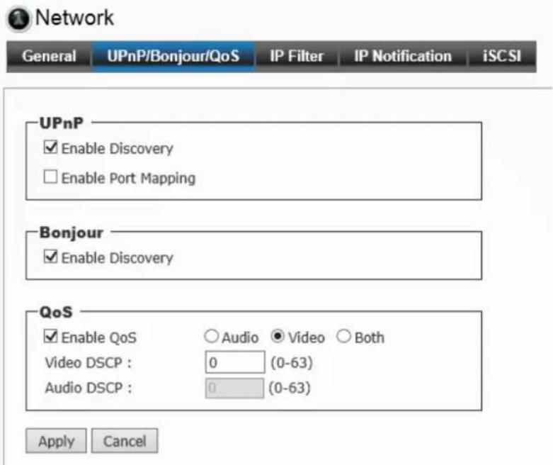
- UPnP: The camera supports UPnP (Universal Plug and Play), which is a set of computer network protocols that enable the device-to-device interoperability. Select the Enable Discovery option to enable the feature.
In addition, it supports port auto mapping function so that you can access into the camera if it behind an NAT router or firewall. Select the Enable Port Mapping option to enable the feature.
- Bonjour: The devices with Bonjour will automatically broadcast their own services and listen for services being offered for the use of others. Select the Enable Discovery option, you can find the camera through the browser with Bonjour and no need to know the IP address.
The Apple Safari is already with Bonjour. You can download the complete Bonjour for Internet Explorer browser from Apple's website by visiting: http://www.apple.com/bonjour/
- QoS (quality of service): It is the ability to provide different priority to different applications or data flows.
- Video DSCP: Assign the DSCP (Diff Serv Code Point) of the stream video from the camera by setting the value from 0 to 63.
- Audio DSCP: Assign the DSCP (Diff Serv Code Point) of the stream audio from the camera by setting the value from 0 to 63.
3. IP Filter
Network

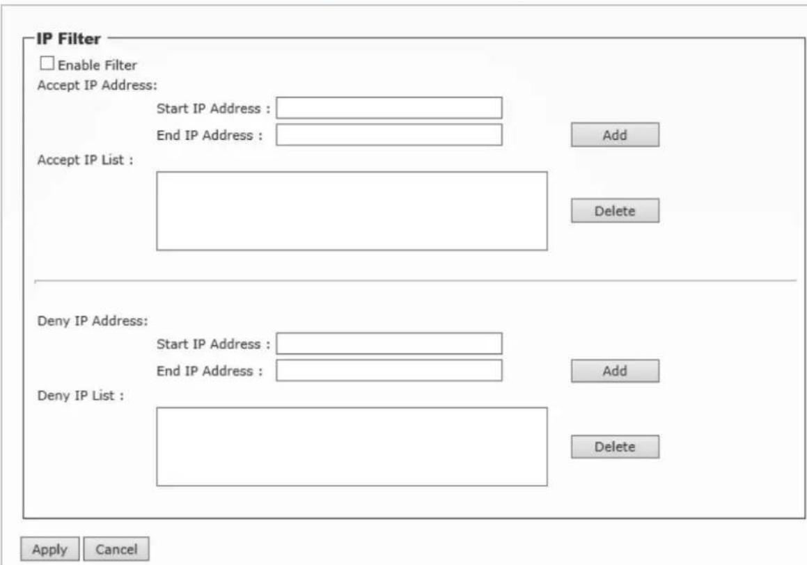
The IP Filter allows the administrator of the camera to restrict the users within a certain range of IP addresses to access into the camera. Select the Enable Filter option and assign the range of IP addresses that are allowed to access into the camera in the Accept IP Address field; or assign the range of IP addresses that are blocked to access into the camera in the Deny IP Address field.
For example, when you enter 192.168.0.50/192.168.0.80 in Start/End IP Address of Accept IP Address and then click Add, the user whose IP address located within 192.168.0.50 \~ 192.168.0.80 will be allowed to access into the camera. On the other hand, if you enter the IP range in Start/End IP Address of Deny IP Address and then click Add, the user whose IP address located within the range will not be allowed to access into the camera.
To remove the assigned range of IP addresses for IP Filter, select the setting in the Accept/Deny IP List and then click Delete.
4. IP Notification
To prevent from the IP address been changed, system is able to send out an alarm. Configure the email setting first if the function is enabled.

Network
General UPnP/Bonjour/QoS IP Filter IP Notification iSCSI
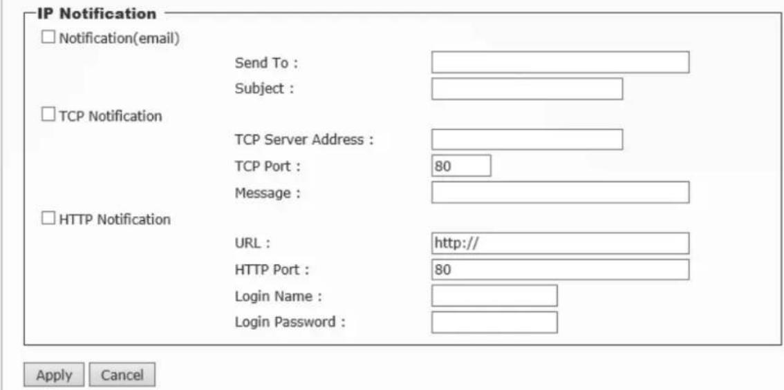
● Notification (email): Select to enable this function.
Send To: Type the receiver's E-mail address.
Subject: Type the subject/title of the E-mail.
● TCP Notification: Select to enable this function.
TCP Server Address: Type the server name or the IP address of the TCP server.
TCP Port: Set port number of TCP server.
Message: The message will be sent to FTP server.
- HTTP Notification: Select to enable this function.
URL: Type the server name or the IP address of the HTTP server.
HTTP Port: Change it only when needed.
HTTP Login name: Type the user name for the HTTP server.
HTTP Login Password: Type the password for the HTTP server.
5. iSCSI
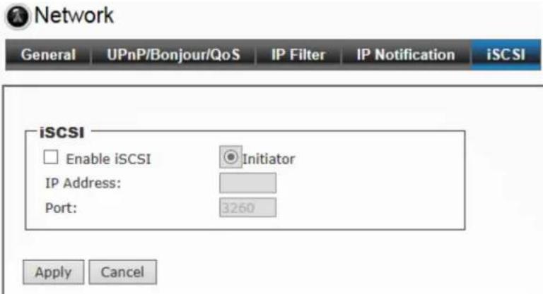
Enable the iSCSI and key-in server IP address and Port number. The disk of the server will be the storage in IP camera setting.
6.2 Video
1. Video Profile
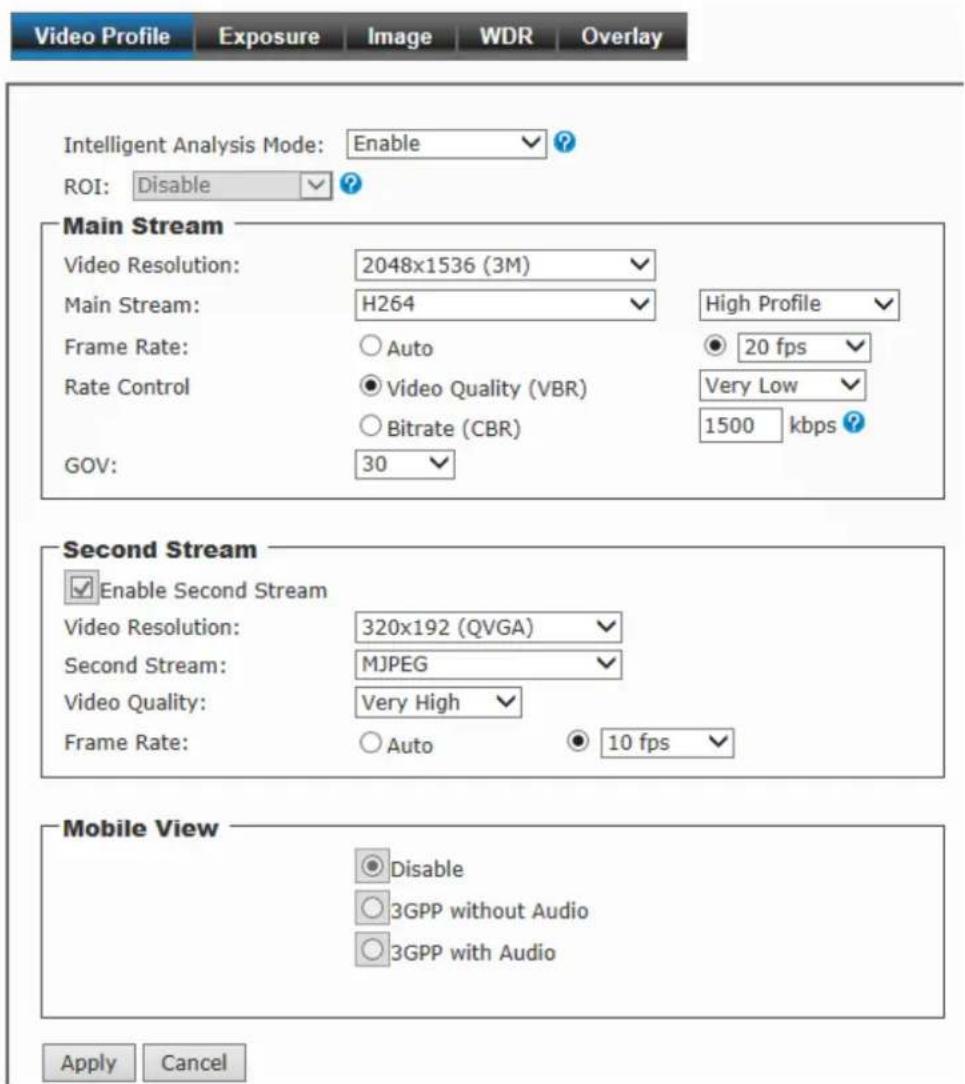
- Intelligent Analysis Mode: You can select Enable or Disable to switch the IVS function.
Note: This item will appear on BU-302-IVS
- ROI: ROI means Region of Interest. When the main stream is set to High Resolution, user can select specified region for monitoring, this can save the bandwidth if there are too many collision on the network.
- Main Stream & Second Stream: It enables the encoder to deliver two totally independent streams of video, separately configured for different frame rates and video resolutions.
- Video Resolution: Select the resolution that you want to see the image on screen from the pull-down menu. It supports several resolution as below:
- 2048 x 1536 (3M)
- 1920 x 1080 (1080P)
- 1280 x 1024 (SXGA)
- 1280 x 960 (960P)
- 1280 x 720 (720P)
- 720 x 480 (D1)
- 640 x 480 (VGA)
- 320 x 240 (QVGA)
- 176 x 144 (QCIF)
You also need to select a proper Frame Rate setting.
In Intelligent Analysis Mode:
- 2048 x 1536 (3M)
- 1920 x 1080 (1080P)
- 1280 x 1024 (SXGA)
- 1280 x 960 (960P)
- 1280 x 720 (720P)
Please be noted that higher resolution and frame rate gets better video quality but larger network bandwidth.
- Main Stream / Second Stream: Select the streaming format as H.264 (High/Main/Baseline Profile) / MPEG4 / MJPEG.
- Rate Control: Set the proper image quality by selecting Video Quality (VBR) or Bitrate (CBR) and then select the desired settings from the pull-down menu.
Select Very Low, Low, Normal, High or Very High for VBR.
Input a bitrate range from 384Kbps to 6Mbps for CBR.
- GOV: Set the GOV value by 1\~100 seconds.
- Mobile View (Not supported by MPEG4): The camera supports 3GPP specification. Select the Disable option to disable this feature. Otherwise, select 3GPP Without Audio or 3GPP With Audio to transfer the video clips without or with audio.
If you use a mobile phone that supports 3GPP, you can also view the real-time streaming image captured by the camera on your phone (with the default player on the phone) by entering the RTSP link:
rtsp://(IP address of the camera)/3gp
Note: Your mobile phone and the service provider must support 3GPP function. Please contact your service provider when you are failed to use this service.
2. Exposure
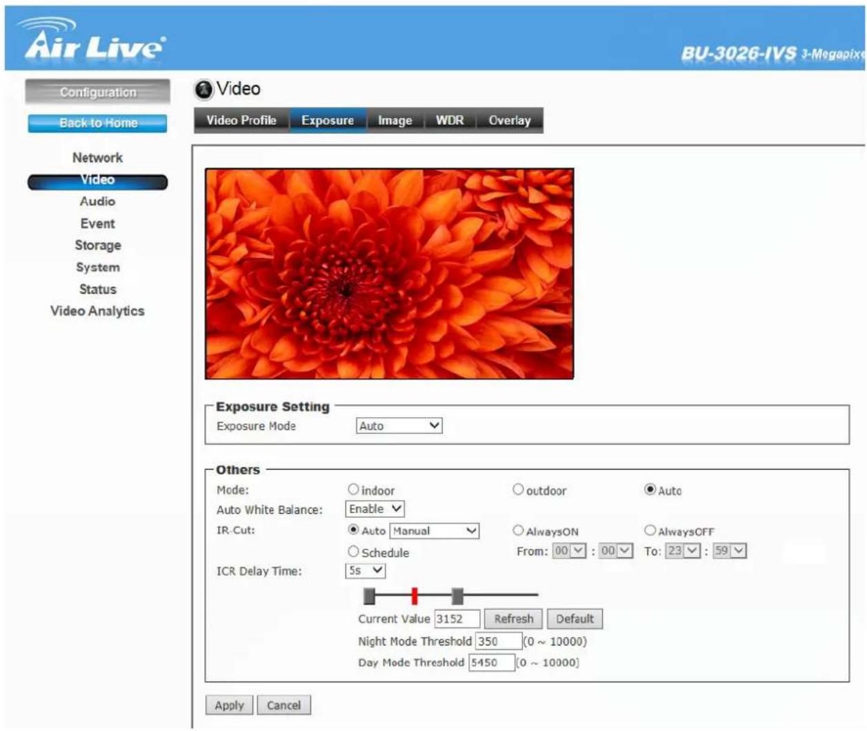
- Exposure Setting: There are three options (Auto / Manual / Clear Motion). When you select Manual mode, you can adjust Exposure Value, Exposure Time and Gain value of the day and night mode.
- Mode: There are three modes (Indoor / Outdoor / Auto) to fit your environment
- Auto White Balance: You can enable or disable the function.
- IR-Cut: The camera can automatically or manually remove the IR-cut filter to let IR light into the sensor during low light conditions.
Auto:
Photo Sensor: The camera automatically removes the filter based on the photo sensor.
Manual: User can use this function to determine the threshold, and the camera switches between day mode and night mode based on this specified threshold.
Always ON:
The camera switches on the IR cut filter at all times to block infrared light.
Always OFF:
The camera switches off the IR cut filter at all times for the sensor to accept infrared light.
Schedule:
The camera switches between day mode and night mode based on a specified schedule. Enter the start and end time for day mode.
- ICR Delay Time: Select from 5s to 30s.
3. Image

Video
Video Profile
Exposure
Image
WDR
Overlay
Image Setting

natural_image
Underwater scene with a bright green and dark object partially submerged in green aquatic vegetation (no visible text or symbols)Day Mode Setting
Brightness:

128
[0..255]
Contrast:

128
[0..255]
Saturation:

128
[0..255]
Sharpness:

128
[0..255]
Default
Night Mode Setting
Brightness:

128
[0..255]
Contrast:

128
[0..255]
Saturation:

128
[0..255]
Sharpness:

180
[0..255]
Default
Others
Mirror:
□Vertical
□ Horizontal
Power Line Frequency:
NTSC/60Hz
○ PAL/50Hz
Apply
Cancel
Image Setting:
● Brightness: Adjust the brightness level from 0\~255.
- Contrast: Adjust the contrast level from 0\~255.
Saturation: Adjust the colors level from 0\~255.
● Sharpness: Adjust the sharpness level from 0\~255.
- Click Default to restore the default value.
Others:
- Mirror: Select Vertical to mirror the image vertically, or select Horizontal to mirror the image horizontally.
- Power Line Frequency: Select the proper frequency according to the camera's location to reduce the flicker: NTSC/60Hz or PAL/50Hz.
4. WDR

Video
Video Profile
Exposure
Image
WDR
Overlay
natural_image
Interior view of an open-plan office with cubicles and employees (no visible text or signage)WDR Setting
WDR:
OFF
?
BLC Setting
BLC:
Low
V
Advance
Digital Noise Reduction:
ON
Fog Compensation:
ON
Apply
Cancel
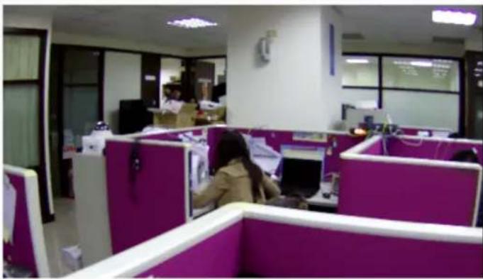
● WDR Setting: WDR is intended to provide clear images even under backlighting, where the intensity of illumination varies a lot.
- BLC Setting: Backlight compensation can get ideal exposure of object which is in front of the strong luminance background
- Advance:
Digital Noise Reduction: A digital filter designed to reduce visible noise for improving visibility of images.
Fog Compensation: Improve visibility of images in fog or smoke by using the Fog compensation function
- Overlay: This option is used to set the image overlay and mask feature of the camera.
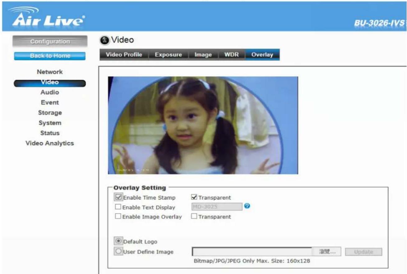
- Enable Time Stamp: Select this option to display the date & time information on the live view image.
- Enable Text Display: Select this option and enter your heading text in the box to display the text information on the live view image.
- Enable Image Overlay: Select Default Logo or User Define Image to display the image overlay on the live view image.
You can set the displayed image in transparent mode by selecting the Transparent option and select the background color as white or black.
When you select User Define Image, you can click Browse to select the image file from your computer and then click Update to apply the setting.
Note: JPG/JPEG file with maximum 65536 bytes.
6.3 Audio
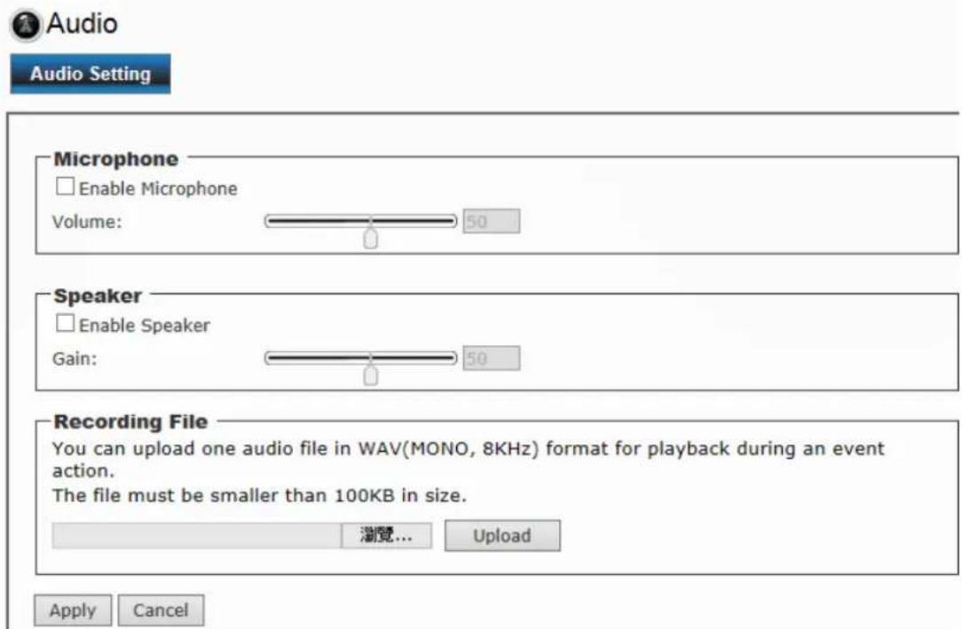
1. Microphone:
- Enable Microphone: Select the option to enable the camera's audio in function, so that you can receive the on-site sound and voice from the camera.
2. Speaker
- Enable Speaker: Select the option to enable the camera's audio out function, so that the connected speaker can play the sound and voice through the camera.
- Recording File: During an event action, you can upload one audio file in WAV (mono, 8KHZ, <100KB in size) for playback.
6.4 Event
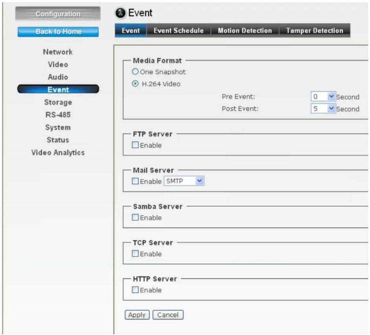
1. Event

Event
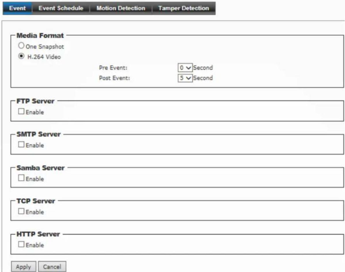
● Media Format: Select One Snapshot to send the alarm message with one still image captured by the camera, or select H264 Video to send the alarm message with one video clip recorded by the camera.
You can set the attachment that is captured in Pre Event or Post Event time when the event has been triggered.
- FTP Server: Select "Enable" to enable the FTP server function.
- FTP Server: Enter the IP address of the target FTP server.
-
User Name: Enter the user name to login into the FTP server.
-
Password: Enter the password to login into the FTP server
- File Path Name: Enter the port number used for the FTP server.
- Test FTP: You can test the FTP server function first here.
Note: Due to the network environment, the camera may not upload number of images that you set.
- SMTP Server: Select "Enable" to enable the SMTP server function.
- SMTP Mail Server: Enter the mail server address. For example, mymail.com.
- Port: Assign the SMTP port in the text box. The default SMTP port is 25.
- Sender Email Address: Enter the email address of the user who will send the email. For example, airlive@mymail.com.
- Receiver #1/#2 Email Address: Enter the first/second email address of the user who will receive the email.
- Subject: Enter the subject of the message for the event.
- Authentication: Select the option according to the mail server configuration.
- User Name: Enter the user name to login the mail server.
- Password: Enter the password to login the mail server.
- Test SMTP: When done, click the button to test the SMTP server function.
- Requires SSL Encryption: If the mail server requires an encrypted connection, you should select the SSL option.
- STARTTLS: Select it if the server needs the STARTTLS encryption.
Note: Due to the network environment, the camera may not upload number of images that you set.
- Samba Event Server: Select "Enable" to enable the Network Storage server for the camera.
- Samba Server Address: Enter the IP address of the Network Storage server.
- Path: Assign the path for uploading the files on the Network Storage server.
- User Name: Enter the user name to login into the Network Storage server.
- Password: Enter the password to login into the Network Storage server.
- Test SMB: When done, click the button to test the network storage server function.
Note: The recorded video files in Network Storage are enclosed by MP4/AVI format without audio.
- TCP Server: Select "Enable" to enable the TCP Server function.
- TCP Server Address: Enter the TCP server address.
- TCP Port: 80. Revise it only needed.
- Message: Enter the message here.
- Test TCP: Click to test the TCP server function.
- HTTP Server: Select "Enable" to enable the TCP Server function.
- URL: Enter the URL path of the HTTP server.
- HTTP Port: 80. Revise it only needed.
- Login Name: Enter the login name of the HTTP server.
- Login Password: Enter the login password of the HTTP server.
- Message: Enter the message here.
- Test HTTP: Click to test the HTTP server function.
2. Event Schedule
Click "Add" for more detail settings.
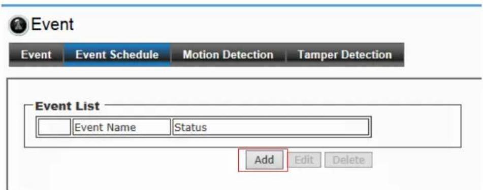
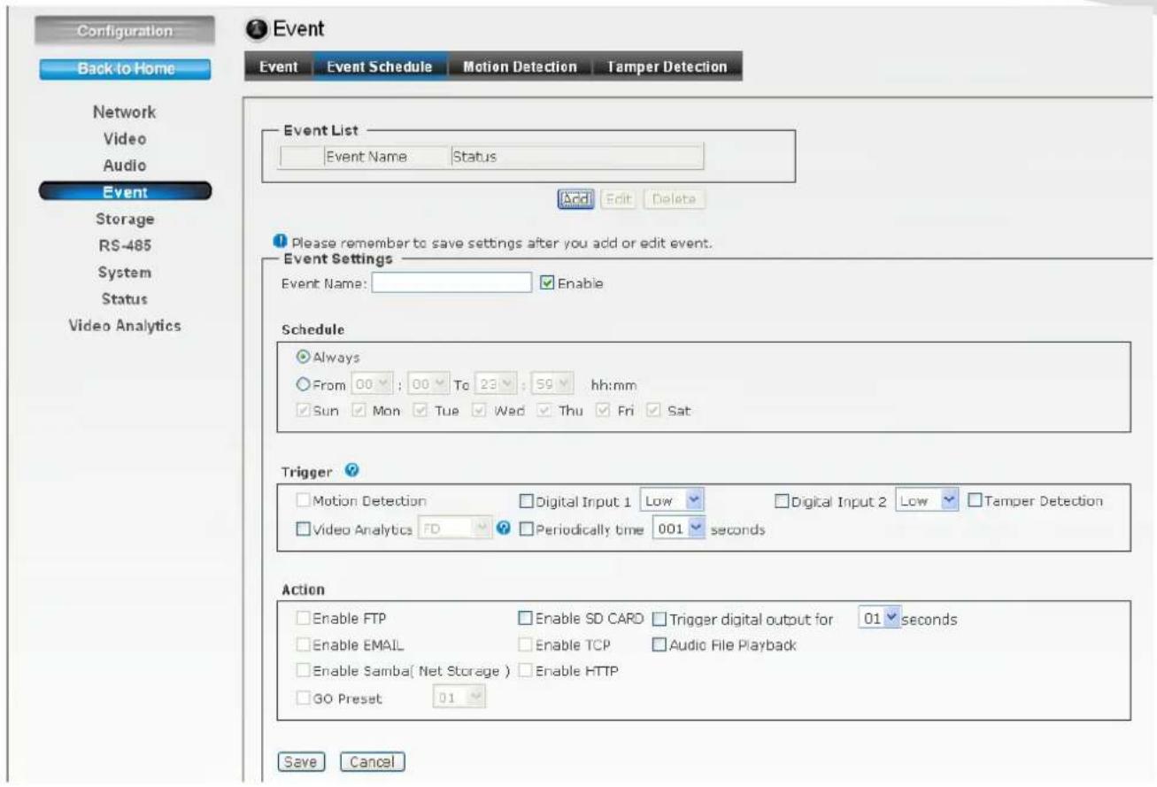
● Follow the steps below to set up the Event Schedule for the camera:
- Select "Enable" and enter the Event Name.
- Schedule: Select to always trigger the event or on specific time period and date.
-
Select the Trigger by: Motion Detection / Digital Input 1 / Digital Input 2 / Tamper Detection / Video Analytics / Periodically time.
-
Action: Select the trigger method.
-
Enable FTP: The camera will upload the attachment to FTP when triggered.
- Enable EMAIL: The camera will send the attachment to the assigned receiver when triggered.
- Enable Samba: The camera will transfer the attachment to the network storage when triggered.
- Enable TCP: The camera will send instant message when triggered.
- Enable SD CARD: Image will be saved into local SD Card when triggered.
-
Enable HTTP: Camera will send the attachment to HTTP server.
-
Trigger digital output: The camera will trigger the connected device on the camera's output for 1\~60 seconds.
- Audio File Playback: Playback a recorded audio file when triggered.
- Modify/Delete: To change/remove the event profile, select the file on the list and click Modify/Delete.
Note: To enable the FTP/Email/Samba/TCP/HTTP services, the required settings of must be completed in Event section.
Motion Detection
The Motion Detection option contains the commands and settings that allow you to enable and set up the motion detection feature of the camera. The camera provides three detecting areas.
Event

-Motion Detection
□ Enable Motion Detection
Window 1
Indicator:
Percentage:
Sensitivity:
Window 2
Indicator:
Percentage:
Sensitivity:
Window 3
Indicator:
Percentage:
Sensitivity:
Apply Cancel
natural_image
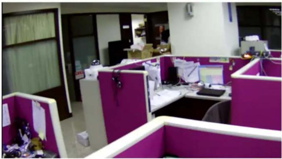
Office cubicle with purple and white workbenches, featuring computers and office equipment (no visible text or symbols)- Follow the steps below to set up the Motion Detection function for the camera:
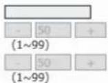
- Select Enable Motion Detection.
- Window 1/2/3: When the detecting area is enabled, you can use the mouse to move the detecting area and change the coverage.
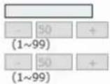
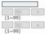
- Set the Percentage and Sensitivity (1\~99) for detecting motion to record video.
- When done, click Apply to save the settings and activate the motion detection function.
3. Tamper Detection
Camera Tamper Detection (CTD) detects tampering events in surveillance cameras that may compromise the integrity of the video content. Examples of camera tampering include obstructing the lens with paint or a foreign object, adjusting the lens' focus or aperture settings, pointing the camera in a different direction, and turning off the lights (if indoors with no major change in ambient illumination expected). CTD can tolerate the effects of automatic camera gain, camera shaking that causes mild image jitter (less than +/- 4 pixels in any direction), and dimly lit scenes.
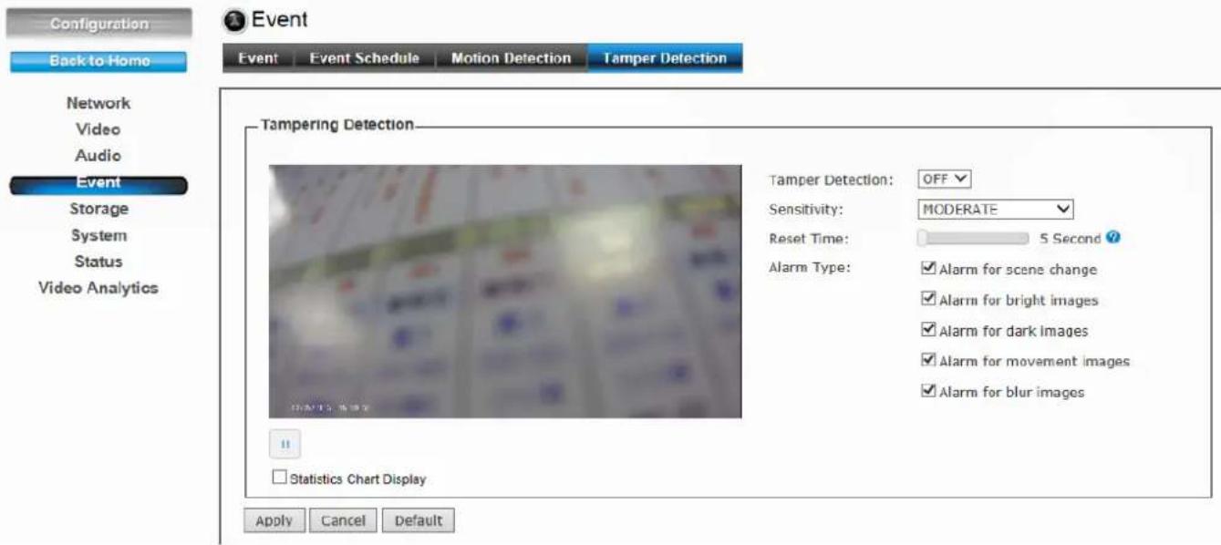
- Select ON/OFF to enable/disable the Tamper Detection.
- Select Sensitivity to set the sensitivity level.
The higher the sensitivity, detects the minutest tampering attempts.
- Select Reset Time. Once a tampering is detected, the camera will resume a normal operating after a certain stability time (Reset Time) during which no detection will be performed.
- Select Alarm Type to specify the activation condition.
● Statistics Chart Display: You can see the test result of alarm type here.
6.5 Storage
1. Recording

Storage

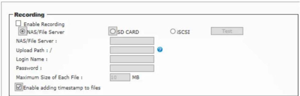

● Recording: Select the option to enable the recording to storage function.
- NAS/File Server: Enter the IP address of the Network Storage/CIFS server.
- Upload Path: Assign the path for uploading the files on the Network Storage/CIFS server.
- Login Name: Enter the user name to login into the Network Storage/CIFS server.
- Password: Enter the password to login into the Network Storage/CIFS server.
- Maximum Size of Each File: This option allows you to limit the file size to be uploaded to the server.
- Timestamp: Select this option to add the date & time information on the attachment.
- Schedule:
- NAS/File Server: Enter the IP address of the Network Storage/CIFS server.
z Schedule: Select "Always" to enable recording continuously or select specific time period and date to record. When done, click Apply to save the settings.
2. Recording List
This page shows the files list information. User may play or delete the selected file.
Note: Please remember to insert a SD card before you start to use this function.

Storage
Recording Recording List
Recording List
Event SD
○ Recording
| Download | Delete | Filename | Date | Time | Size | |
| First Page | Previous | Next | Final Page | |||
Please enable event schedule, action SD CARD/Please insert SD CARD!!
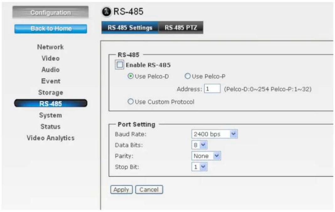
6.6 RS-485
1. RS-485 Setting
The RS-485 option provides the control settings for external device through the I/O port. Select Enable RS-485 and complete the required settings to activate the RS-485 function of the camera.
z Use Pelco-D: Select this option and then select an Address. When you enable the RS-485 function of the camera, you will be able to use the RS-485 Buttons on the live view screen to control the camera.
z Use Custom Protocol: Select this option to configure the commands protocol manually. When you select this option, you need to complete the required settings of Port Setting.
You can click Test to test each command that you have assigned. In the Extended Command 1\~5 string boxes, you can customize more buttons and settings for your needs. Please note that the setting values in the Command Name string boxes should be from the connected external device (please refer to the manual of the connected device).
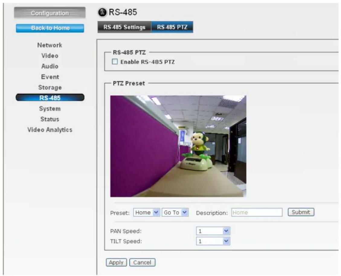
2. RS-485>>RS-485 PTZ
You can enable RS-485 PTZ function when you have Pan/Tilt Head.
6.7 System
The System menu contains sub-menus as below. When completed, click Apply to save the settings.

System
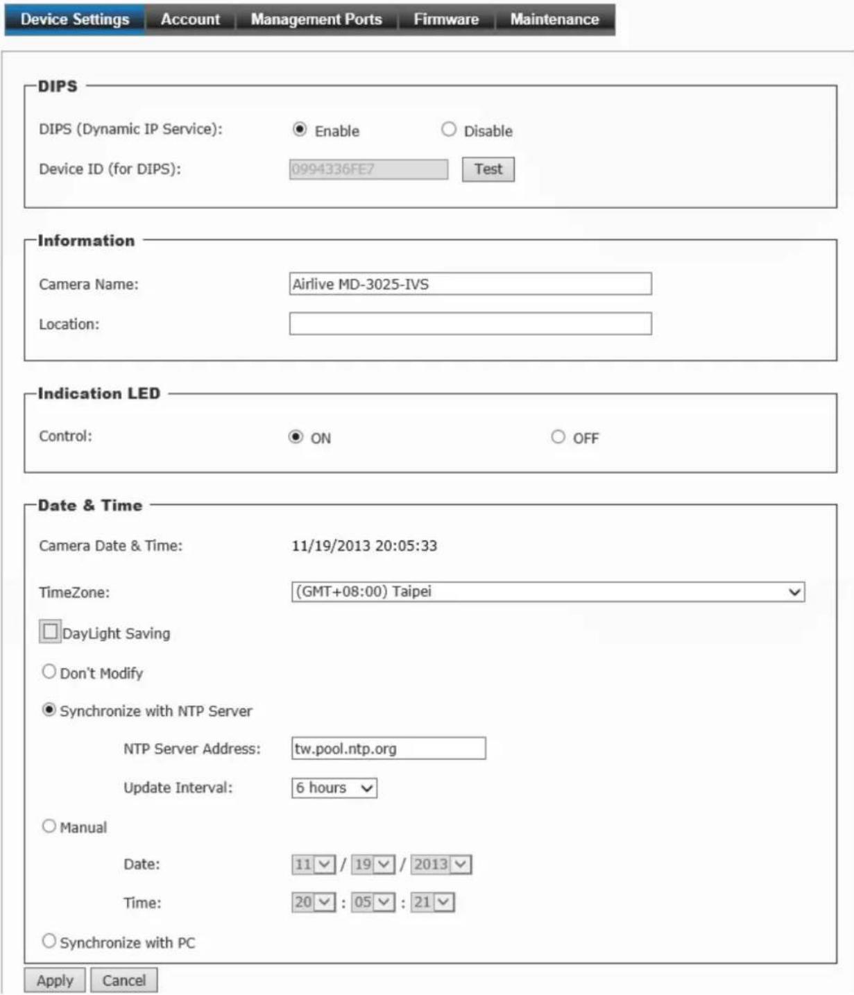
1. Device Settings
DIPS:
- DIPS (Dynamic IP Service): To enable or disable the DIPS® (Dynamic IP Service) function.
- Device ID (for DIPS): It's a unique number of each device for identification.
- Information: This item allows you to assign the camera name and location information.
- Camera Name: Enter a descriptive name for the camera, which is helpful to identify the camera easily while multiple cameras are connected within the network.
-
Location: Enter a descriptive name for the location where is monitored by the camera.
-
Indication LED: This item allows you to set the LED illumination as desired. The available options include: ON and OFF.
● Date and Time: Enter the correct date and time for the system. -
Camera Date & Time: It shows the current date and time.
- Time Zone: Select the proper time zone for the region from the pull-down menu.
- Day Light Saving: Select this option if the Daylight Saving Time is used in your location.
Daylight Saving means a period from late spring to early fall, and during the period many countries will set their clocks ahead of normal local time by one hour to give more daytime light in the evening.
- Don't Modify: Select this option to set the date and time as system's default settings.
- Synchronize with NTP Server: Select this option and the time will be synchronized with the NTP Server. You need to enter the NTP Server Address of the server and set the Update Interval.
- Manual: Select this option to set the date and time manually.
- Synchronize with PC: Select this option and the date & time settings of the camera will be synchronized with the connected computer.
2. Account

System
Device Settings
Account
Management Ports
Firmware
Maintenance
Viewer Login
○ Anonymous
- Only users in database
Save
Admin
Password:
Confirm Password:
Modify
Users
User Name :
Password :
Confirm Password:
User List :
Add
Delete
Guest
User Name :
Password :
Confirm Password:
Guest List :
Add
Delete
- Viewer Login: Anonymous means user can login without user name and password. Or select "Only users in database" to limit the authentication.
- Admin: To prevent unauthorized access to the camera's Web Configuration, you are strongly recommend to change the default administrator password. Type the administrator password twice and then click Modify to set and confirm the password.
- Users
- User Name/Password/Confirm Password: Enter the user's name you want to add to use the camera. Then, enter the password twice for the new user. When done, click Add to add the new user for the camera.
- User List: Display the existing users of the camera. To delete a user, select the one you want to delete and click Delete.
- Guest
- User Name/Password/Confirm Password: Enter the user's name you want to add to use the camera. Then, enter the password twice for the new user. When done, click Add to add the new user for the camera.
- Guest List: Display the existing guests of the camera. To delete a guest, select the one you want to delete and click Delete.
Note: The "Users" can access the camera and control the Function buttons of the camera's Web Configuration; the "Guest" can only view the live view image from the Main screen of the Web Configuration while accessing the camera. Only the "Admin" is allowed to configure the camera through the Web Configuration.
3. Management Ports
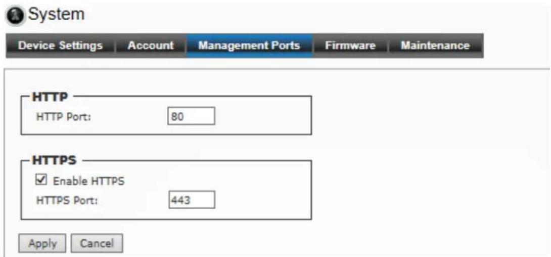
- HTTPS: Select the Enable HTTPS option to enable HTTPS which is a secure protocol to provide authenticated and encrypted communication within your network.
- HTTPS Port: Assign a HTTPS port in the text box. The default HTTPS port is 443.
4. Firmware
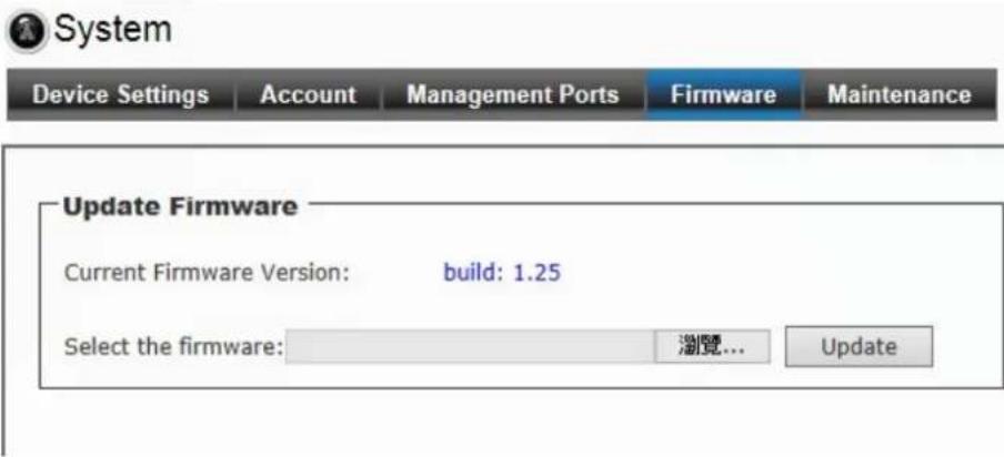
- Update Firmware: You can upgrade the firmware for your camera once you obtained a latest version of firmware.
- Current Firmware Version: It displays the current firmware version.
- Update: Click Browse to locate the firmware file and then click Update.
Warning!!!
The download firmware procedure cannot be interrupted. If the power and/or network connection are broken during the download procedure, it might possibly cause serious damage to the device. Strongly suggest that DO NOT upgrade firmware via Wireless LAN due to high error rate possibly and don't allow any other clients to access this unit during updating procedure. Be aware that you should not turn off the power during updating the firmware and wait for finish message. Furthermore, the firmware upgrade procedure always is risk and do not try to upgrade new firmware if it's not necessary.
5. Maintenance

System
Device Settings
Account
Management Ports
Firmware
Maintenance
Factory Reset
Factory reset will restore all the settings to factory default
Reset
Factory reset will restore all the settings to factory default (Excluding Network Setting)
Reset
System rebooted
Reboot
Configuration Backup
Backup
Backup To SD CARD Device
Configuration Restore
Select the configuration file to restore:
瀏覽...
Restore
Restore From SD CARD Device
Format
SD Card
● Factory Reset: Click Reset to restore all factory default settings for the camera.
- System rebooted: Click Reboot to restart the camera just like turning the device off and on. The camera configuration will be retained after rebooting.
- Configuration Backup: You can save your camera configuration as a backup file on your computer. Whenever you want to resume the original settings, you can restore them by retrieving the backup file.
- Backup: Click the button to save the current configuration of the camera.
- Backup to SD CARD Device: Click to save the configuration file to SD card.
- Configuration Restore: lick Browse to locate the backup file on your PC and then click Restore.
- Restore From SD CARD Device: Restore the backup file from SD card.
- Format: Click to format the SD card.
6.8 Status
The Status menu shows the current status of the camera, including the basic information, audio/video settings, networking configuration, and system logs.

Status
Basic
Audio/Video
Network
System Log
Basic
Camera Name: Airlive MD-3025-IVS
MAC: 00:41:01:2E:32:D5
Camera Date & Time: 01/14/2014 13:31:18
1. Basic
It provides the basic information as above.
2. Audio/Video
It provides the information including H.264/MJPEG/Mobile View/Audio as below.

Status
Basic
Audio/Video
Network
System Log
MPEG4
Video Resolution: 1920x1080 (1080P)
Video Quality: Very High
Frame Rate: 25 fps
MJPEG
Video Resolution: 320x192 (QVGA)
Video Quality: Very High
Frame Rate: 10 fps
Mobile View
3GPP Enable: Disable
Audio
Microphone Gain: +10 dB
Speaker Out: Enable
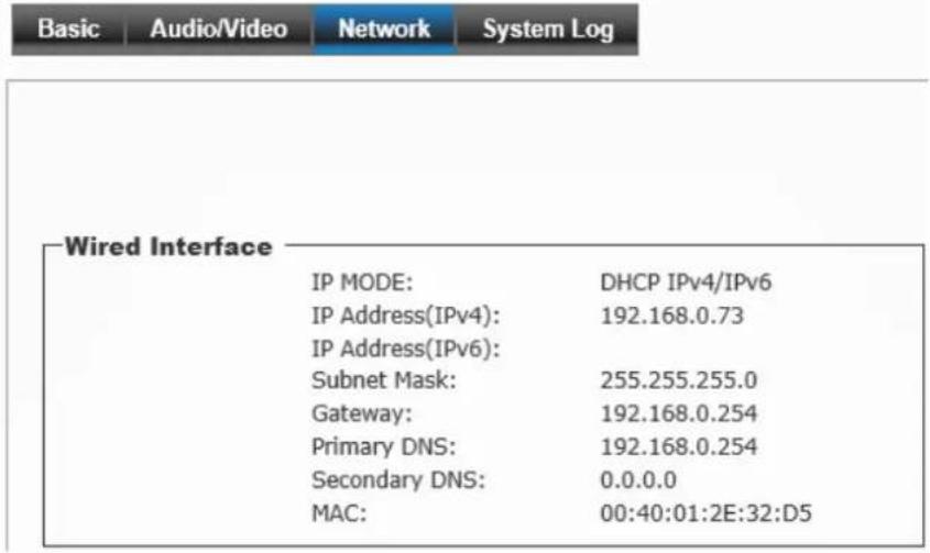
- Network: It provides the information including IP/LAN as below.
Status
- System Log: It provides the log information as below.
Status
![Basic Audio/Video Network System Log Syslog Enable remote log IP Address: Port: 514 Save Log List Item Date and Time Event 1. 10/23/2013 14:52:22 admin login on 192.168.0.184 2. 10/23/2013 14:21:43 admin login on 192.168.0.29 3. 10/23/2013 14:21:11 admin login on 192.168.0.29 4. 10/23/2013 14:16:30 [EVENT MGR]:Trigger By Motion Detection 5. 10/23/2013 14:15:55 [EVENT MGR]:Trigger By Motion Detection 6. 10/23/2013 14:09:32 [EVENT MGR]:Trigger By Motion Detection 7. 10/23/2013 14:08:52 [EVENT MGR]:Trigger By Motion Detection 8. 10/23/2013 13:51:11 admin login on 192.168.0.29 9. 10/23/2013 13:18:21 admin login on 192.168.0.29 10. 10/23/2013 13:17:15 admin login on 192.168.0.29 11. 10/23/2013 13:13:07 admin login on 192.168.0.29 12. 10/23/2013 13:12:48 admin login on 192.168.0.29 13. 10/23/2013 12:27:47 [EVENT MGR]:Trigger By Motion Detection 14. 10/23/2013 11:59:23 [EVENT MGR]:Trigger By Motion Detection 15. 10/23/2013 11:29:03 [EVENT MGR]:Trigger By Motion Detection 16. 10/23/2013 11:28:50 admin login on 192.168.0.29 17. 10/23/2013 11:27:24 Sync with NTP server: [2013/10/23 11:27:24] 18. 11/07/2013 03:25:28 [RTSP SERVER]:Start one session<192.168.0.75> 19. 11/07/2013 03:25:27 [RTSP SERVER]:Stop one session<192.168.0.75> 20. 11/07/2013 03:25:24 [NET]:UPnPAV Disable First Page Previous Next Final Page Delete](/content/2026/06/1202485/images/3598932670fa31fd1b4b91e221a27f7695da0eb3b1ba4db18642a02e7e297470.jpg)
- Enable remote log: Enter the IP address to enable the remote log function.
7
Appendix
A. Video Analytics (Only for BU-3026-IVS)
BU-3026-IVS provides multiple intelligent video analytics that helps you to save your human resources and reach the goal of automatic surveillance.
Please go to Configuration→Video Analytics to experience the entire IVS function.
Note: Only one Video Analytics function can be excuted at same time.
When using Video Analytics, we will recommend you to use 2-Megapixel resolution for best performance. If 3-Megapixel resolution is selected, only Face Detection will be available.
A.1 Face Detection:
Face detection is a precise feature which needs highly accurate rate of recognition on human faces only. The software is able to count how many faces in the image and also highlights those faces simultaneously so the administrator will be easier to look in details on each face at specific environment.
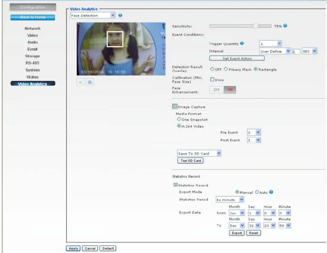
- Sensitivity: Adjust sensitivity 0\~100%, the higher sensitivity means more precisely and detailed face detection.
- Event Conditions: Once you want to change the trigger condition, you have to select the event interval by NONE, Daily, Hourly or User Define and Quantity. For example, if you set Trigger Quantity for 5 people and interval with “1 Minute”, IP Camera detects 5 faces will trigger alarm. In the following one minute, camera won’t trigger alarm even though there are more than 5 faces are detected. After one minute, camera will trigger alarm again if it detects 5 faces again.
- Set Event Action: Go to the Event Schedule to Add or Edit the IVS event.
- Detection Result Overlay: Select OFF, Privacy Mask or Rectangle to be shown on the face when any face has been detected.
- Calibration (Min. Face Size): Face detection requires the min. face size is 20x20 pixels, so you can use this for reference.
● Face Enhancement: Enable this function for more accuracy.
- Image Capture: Enable this function to save the image to Samba server or SD card.
Note: When you change the media format, it will effect all the existed events.
● Statistics Record: This function can record how many faces have been detected. You can configure your camera in different ways to generate the statistics you required and statistic data can be exported in csv format file.
- Select Auto, camera can send yesterday report to Samba server or FTP server automatically.
- Select Statistics Period to specify the period you want the data for.
- Select the range to export the data or press "Reset" to delete it.
● Statistics Chart Display: Enable this to see the detection result by chart.
A.2 Face Recognition:
The key feature of Face Recognition is to recognize faces for access control or any suspicious persons in camera which match the database. You can save up to 10 face images to the AirLive BU-3026-IVS for recognition, so when the camera catch the face which match the database, the camera will trigger related output devices by necessary reaction.
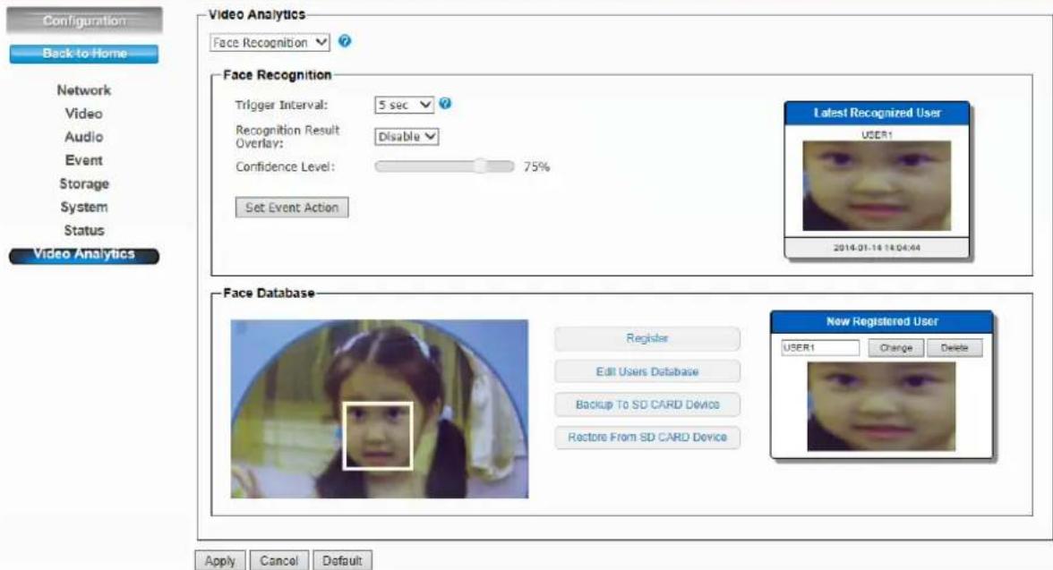
- Select proper alarm time in Trigger Interval.
- Select to Enable/Disable the overlay in Recognition Result Overlay. All the detected face will be shown on the live view screen.
-
Select Confidence Level to set the confidence threshold when compared to the faces in the database.
-
Set Event Action: Go to the Event Schedule to Add or Edit the IVS event.
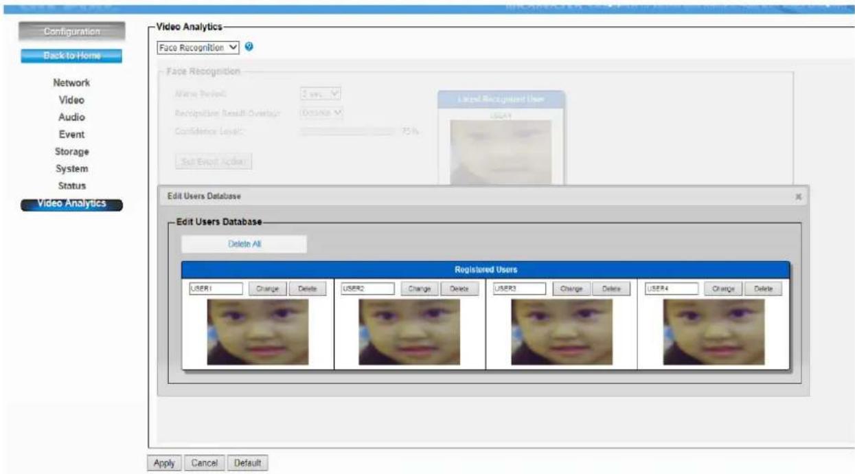
- Register function supports memorizing up to 10 results of face recognition into the database. Also you can select to edit the database, backup to or restore from the SD card device.
- Edit Users Database: You can edit the registered database here. (See below)
A.3 iMotion Detection (Intelligent Motion Detection)
Intelligent Motion Detection is able to increase the accuracy of motion detection and also provides more flexible setting with polygon for the zones. Any moving object in the zone will trigger this alarm. Objects must move and stay within the boundary for at least 100 ms.
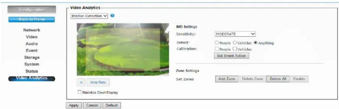
- Select Sensitivity to set the detection sensitivity level. Higher sensitivity will make it easier to detect and less objects missing, but more misjudgments.
- Select People / Vehicles / Anything as the detected objects.
-
Select Calibration (People or Vehicle Object Sizes). The minimum and maximum boundary of objects can be specified to improve the detection accuracy. The width and length values must be at least 6 pixels. If any false detection caused by smaller objects, you can try to increase the minimum size.
-
Min. Size of Calibration: The width and length values must be 6 pixels at least. If any false detection caused by smaller objects, you can try to increase the minimum size.
- Max. Size of Calibration: It has to be larger than the minimum size and half the frame size is the most.
- Go to the Event Schedule to Add or Edit the IVS event in the Set Event Action.
- Up to 4 zones can be specified when click the Add Zone function. Left click to add the point and 15 points at most can be used in each zone.
- Select Delete Zone/All to delete the zones
- Select Enable/Disable to allow the trigger or not.
A.4 Trip Zone
The Trip Zone is an area protection based on two virtual areas with a line in center. Any object moves across the line within 0.5 second at least will trigger the alarm and send out an alert. It can be set to detect one direction or both directions. It is very useful to some surveillance environments like walls, railroad platform, parking lot entrance or any intersection where needs to monitor the “Against Traffic”.
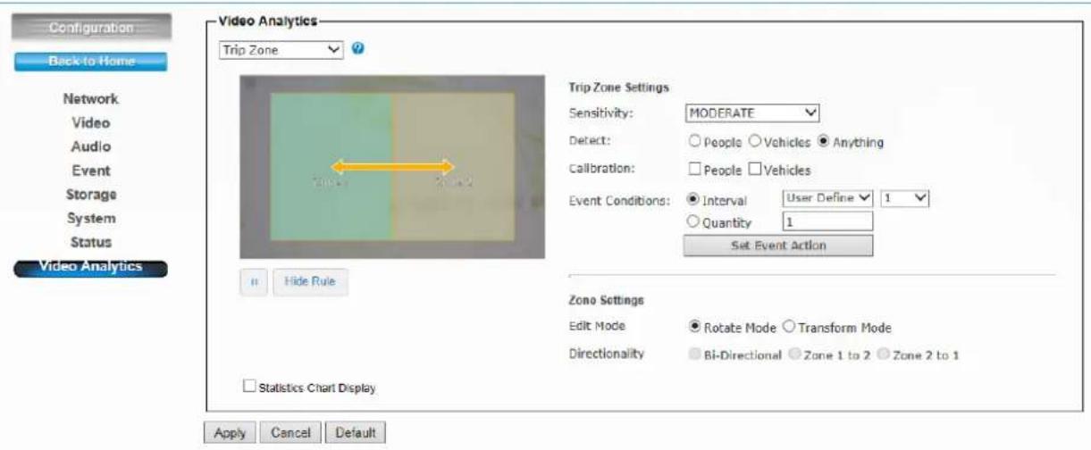
- Select Sensitivity to set the detection sensitivity level. Higher sensitivity will make it easier to detect and less objects missing, but more misjudgments.
-
Select People / Vehicles / Anything as the detected objects.
-
Select Calibration (People or Vehicle Object Sizes). The minimum and maximum boundary of objects can be specified to improve the detection accuracy. If any false detection caused by smaller objects, you can try to increase the minimum size.
- In Event Conditions, you can specify the minimum time interval and quantity (500 at most) for each alarm. And go add or edit the IVS event in the Set Event Action.
-
Select Rotate Mode or Transform Mode in Edit Mode.
-
Rotate Mode: User can rotate the zone at will.
- Transform Mode: User can drag the point of the zone to any shape.
- Directionality: User can select the detected moving direction from one to another or both the directions
● Statistics Chart Display: Here will show the result of Trip Zone.
A.5 Object Counting
The Object Counting makes store owners easier to calculate the number of people in and out of the store. You may choose one way or two way directions for counting. The numbers can be displayed on screen and saved to the database. It is also useful to calculate the amount of traffic flow on the highway.
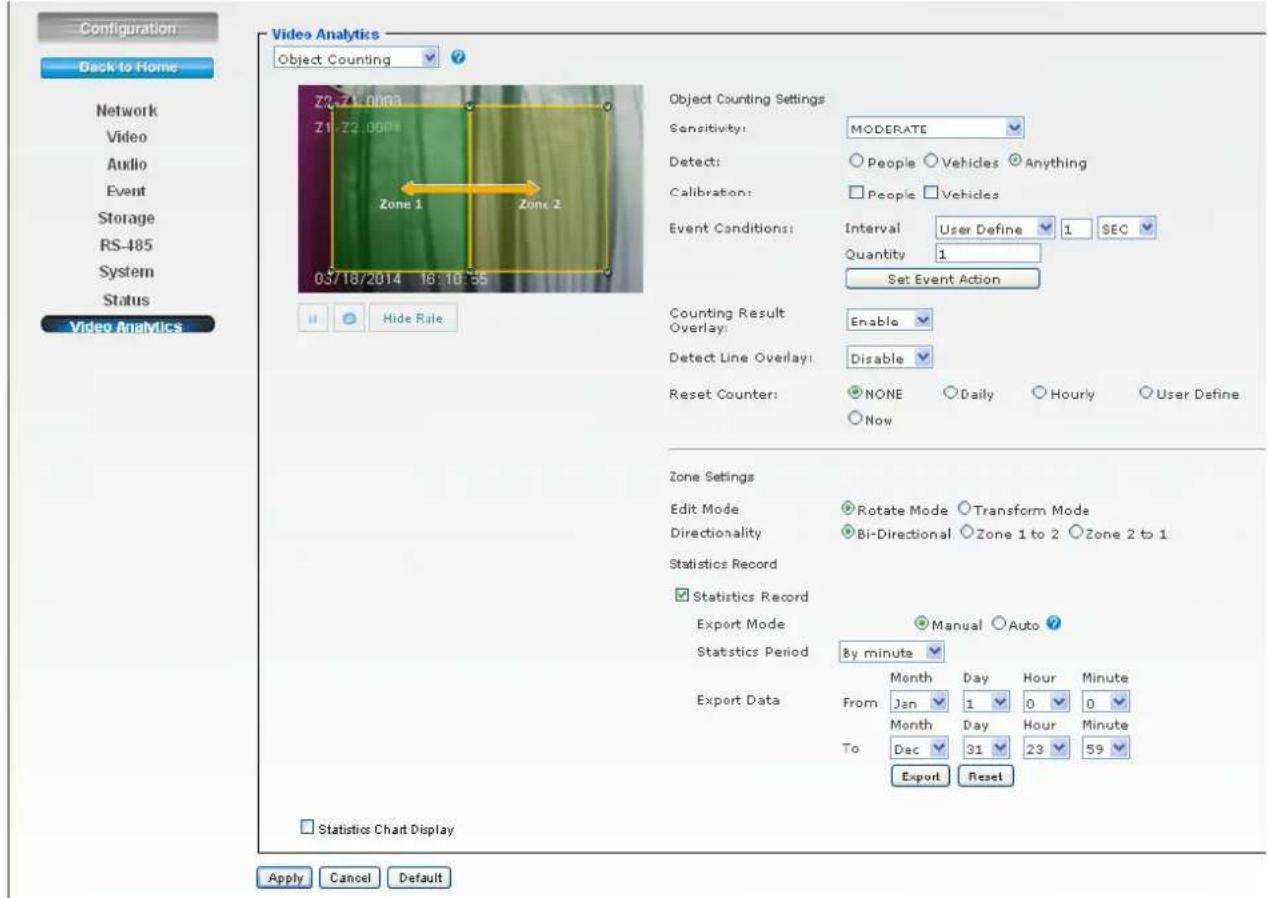
- Select Sensitivity to set the detection sensitivity level. Higher sensitivity will make it easier to detect and less objects missing, but more misjudgments.
- Select People / Vehicles / Anything as the detected objects.
- Select Calibration (People or Vehicle Object Sizes). The minimum and maximum boundary of objects can be specified to improve the detection accuracy. If any false detection caused by smaller objects, you can try to increase the minimum size.
-Min. Size of Calibration: The width and length values must be 6 pixels at least. If any false detection caused by smaller objects, you can try to increase the minimum size. - Max. Size of Calibration: It has to be larger than the minimum size and half the frame size is the most.
- In Event Conditions, you can specify the minimum time interval and quantity for each alarm. And go add or edit the IVS event in the Set Event Action.
● Enable / Disable the Counting Result Overlay.
● Enable / Disable the Detect Line Overlay. - Reset Counter: Select the minimum time interval to reset the counter result.
- Select Rotate Mode or Transform Mode in Edit Mode:
- Rotate Mode: User can rotate the zone at will.
- Transform Mode: User can drag the point of the zone to any shape
- Directionality: User can select the detected moving direction from one to another or both the directions.
● Statistics Record: You can configure your camera in different ways to generate the statistics you required and statistic data can be exported in csv format file.
- Select Auto, camera can send yesterday report to Samba server or FTP server automatically.
- Select and choose the Statistics Period that you want and also you can export or reset the result.
- Statistics Chart Display: Here will show the result of Trip Zone.
A.6 e-Fence
The e-Fence is an electronic fence protection system which is able to detect and send output alert if any object is entering or leaving the boundaries you set in the camera. This function can be used in many applications, either as a standalone protection system or other protection systems such as airports, power plants, radio towers or even military camps.
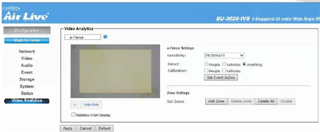
- Select Sensitivity to set the detection sensitivity level. Higher sensitivity will make it easier to detect and less objects missing, but more misjudgments.
- Select People / Vehicles / Anything as the detected objects.
-
Select Calibration (People or Vehicle Object Sizes). The minimum and maximum boundary of objects can be specified to improve the detection accuracy. The width and length values must be at least 6 pixels. If any false detection caused by smaller objects, you can try to increase the minimum size.
-
Min. Size of Calibration: The width and length values must be 6 pixels at least. If any false detection caused by smaller objects, you can try to increase the minimum size.
-
Max. Size of Calibration: It has to be larger than the minimum size and half the frame size is the most.
-
Set Event Action: Go to the Event Schedule to Add or Edit the IVS event.
- Up to4 zones can be specified when click the Add Zone function. Left click to add the point and 15 points at most can be used in each zone.
- Select Delete Zone/All to delete the zones.
- Select Enable/Disable to allow the trigger or not.
● Statistics Chart Display: Here will show the detection result of e-Fence.
- Air Live®
- Powered by OvisLink Corp.
- Copyright & Disclaimer
- FCC Statement
- Federal Communication Commission Interference Statement
- FCC Caution
- FCC Radiation Exposure Statement
- WEEE Marking Warning:
- Table of Contents
- Overview....1
- Package Contents and Installation....7
- Using IP Camera via Web Browser....12
- Operating IP Camera via iOS/Android Device....13
- Operating the Network Camera ....16
- Configuration ....19
- Appendix....53
- 1
- Overview
- Introduction
- Features
- Product Specification
- System Requirement
- 2
- Package Contents and Installation
- Package Contents
- Connections
- Power Source Requirement
- Connector
- Connect to IP Camera
- 3
- Using IP Camera via Web Browser
- Windows Web Browser
- 4
- Operating IP Camera via iOS/Android Device
- Using IP Camera via iOS/Android device
- Click Add button
- Click Auto Search button and select the camera.
- 5
- Operating the Network Camera
- Live View
- Configuration
- 6
- Configuration
- Network
- General
- Network
- LAN Interface
- Multicast
- PPPoE
- DDNS
- UPnP/Bonjour/ QoS
- IP Filter
- IP Notification
- iSCSI
- Video
- Video Profile
- Exposure
- Auto:
- Always ON:
- Always OFF:
- Schedule:
- Image
- Others
- Image Setting:
- Others:
- WDR
- Video
- WDR Setting
- BLC Setting
- Advance
- - Advance:
- Audio
- Microphone:
- Speaker
- Event
- Event
- Event Schedule
- Motion Detection
- Event
- -Motion Detection
- Tamper Detection
- Storage
- Recording
- Recording List
- Storage
- Recording Recording List
- Recording List
- RS-485
- RS-485 Setting
- RS-485>>RS-485 PTZ
- System
- System
- Device Settings
- DIPS:
- Account
- Admin
- Users
- Guest
- - Users
- - Guest
- Management Ports
- Firmware
- Warning!!!
- Maintenance
- Factory Reset
- System rebooted
- Configuration Backup
- Configuration Restore
- Format
- Status
- Status
- Basic
- Basic
- Audio/Video
- MPEG4
- MJPEG
- Mobile View
- Audio
- 7
- Appendix
- Video Analytics (Only for BU-3026-IVS)
- A.1 Face Detection:
- A.2 Face Recognition:
- A.3 iMotion Detection (Intelligent Motion Detection)
- A.4 Trip Zone
- A.5 Object Counting
- A.6 e-Fence
Brand : AIRLIVE
Model : BU-3026
Category : Security Camera