
RS-P90 - Cassette player PIONEER - Free user manual and instructions
Find the device manual for free RS-P90 PIONEER in PDF.

| Product type | Stereo cassette player |
| Brand | Pioneer |
| Model | RS-P90 |
| Dimensions (W x H x D) | 420 x 130 x 280 mm |
| Weight | 6.5 kg |
| Power supply | 220-240 V, 50/60 Hz |
| Power consumption | 25 W |
| Heads | Ferrite read/write head (dual head) |
| Motor | Brushless DC motor |
| Signal-to-noise ratio | Greater than 70 dB (with Dolby NR) |
| Frequency response | 20 Hz - 20 kHz (normal cassette) |
| Wow and flutter | Less than 0.05% WRMS |
| Cassette formats | Type I, II, IV |
| Noise reduction | Dolby B, C, HX Pro |
| Main functions | Play, record, stop, pause, fast forward/rewind, automatic music search (AMS) |
| Inputs | Line In (RCA), Mic (6.35 mm jack) |
| Outputs | Line Out (RCA), Headphone (6.35 mm jack) |
| Maintenance and cleaning | Regular head cleaning with isopropyl alcohol and cotton swab. Disassemble the deck to access the heads. |
| Safety | Disconnect before maintenance. Do not expose to moisture. |
| Spare parts and repairability | Heads, belts, and motors available from specialized dealers. Repair possible by qualified technician. |
| General information | Product from the 1990s, Japanese manufacturing. |
Frequently Asked Questions - RS-P90 PIONEER
User questions about RS-P90 PIONEER
0 question about this device. Answer the ones you know or ask your own.
Ask a new question about this device
Download the instructions for your Cassette player in PDF format for free! Find your manual RS-P90 - PIONEER and take your electronic device back in hand. On this page are published all the documents necessary for the use of your device. RS-P90 by PIONEER.
USER MANUAL RS-P90 PIONEER
Optical Digital Reference System
Universal Digital Preamp

Owner's Manual
RS-P90
English
Key Finder 4
Head unit (RS-D7RII) 4
Remote control (RS-D7RII) 4
Opening and closing the remote control cover .... 5
- When the cover is closed
- When the cover is open
Before Using This Product 7
About this unit 7
About this manual 8
In case of trouble 8
Product registration 8
About the digital network 9
Resetting the microprocessor 10
Audio Adjustment 11
Audio menu 11
- Switching to the audio menu
Audio Adjustment 12
Main menu 12
- Switching to the main menu
Balance adjustment 12
Bass/treble adjustment 13
Using the compression 14
Adjusting the listening position 15
● Using the position selector
● Fine tuning the position
● Effective distance adjustment using the position fine tuning function
Source level adjustment 19
Audio Adjustment ...... 20
About the equalizer menu 20
● 31 band graphic equalizer
● 3 band parametric equalizer
Equalizer menu 21
- Switching to the equalizer menu
Relation between frequency characteristics and sound quality 22
Adjusting the 31 band graphic equalizer ..... 24
Adjusting the 3 band parametric equalizer ..... 25
- About the adjustment using the parametric equalizer
- Setting the equalizer curve
The flat function 28
The clear function 29
Audio Adjustment ...... 30
What is the multi-amp system? 30
Network menu 31
- Switching to the network menu
Time alignment adjustment 32
- Switching to the
time alignment adjustment mode
● Measuring the distance to be corrected
- Inputting the distance to be corrected
Filter adjustment 36
- Switching to the filter adjustment mode
● Using the mute function
- Adjusting the filter
Switching between linear phase characteristics/minimum delay phase characteristics 41
● Linear phase characteristics
● Minimum delay phase characteristics
- Switching between linear phase characteristics/minimum delay phase characteristics
Audio Adjustment 42
Memory functions of adjusted audio menu 42
Switching to memory mode 43
- Equalizer menu
● Network menu
Storing the adjustment data in memory 44
Recalling data stored in memory 45
- Recalling memory using forward/reverse order — Functions of equalizer menu —
- Specifying the memory number directly
Memory protect function 47
Display for the Person who Set Up the Audio Adjustments 48
Inputting the name 48
Inputting characters 48
Memory Data Memo 51
Connecting the Units 54
WARNING 54
CAUTION 54
Routing the optical cable 55
Setting example 55
Connection diagram 56
Connecting the RCA input amplifier 57
Connecting the power terminal 58
Secure the optical cable 59
Installation 60
Installing the unit 60
Troubleshooting 61
Checklist 61
Specifications 62
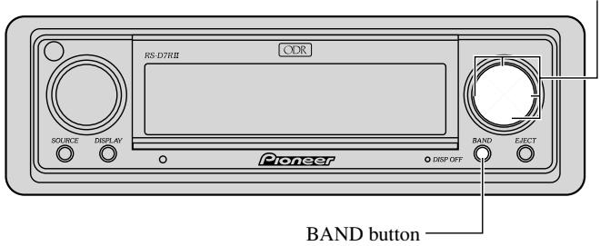
Head unit (RS-D7RII)
This unit can be operated with the combined head unit RS-D7RII (sold separately).
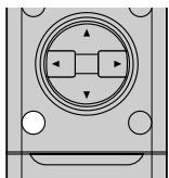
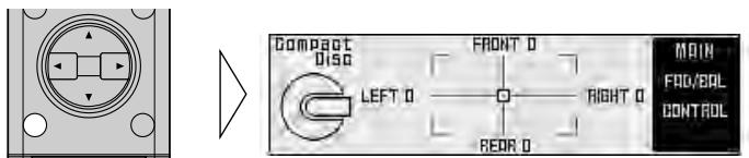
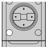
▲/▼/◄/► buttons
These buttons can not be used in the Audio Adjustment operation.
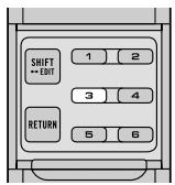
Remote control (RS-D7RII)
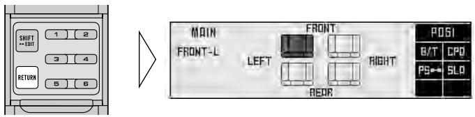
Most of all functions can be operated by the remote control.
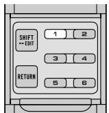
Opening the cover enables the SHIFT, RETURN and FUNCTION buttons 1 to 6 inside the remote control. For more details, refer to the page 5.
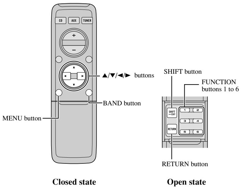
Opening and closing the remote control cover
When the remote control is opening the cover enables the SHIFT, RETURN and FUNCTION buttons 1 to 6 inside the unit.
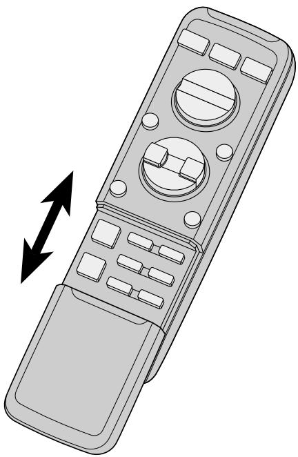
natural_image
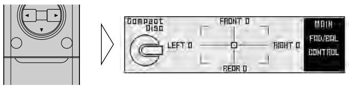
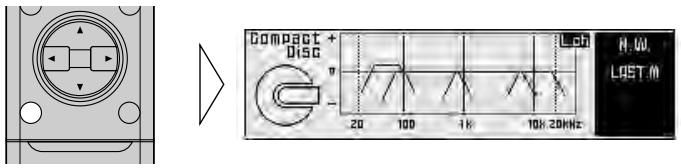
Line drawing of a remote control device with directional arrows indicating left and right motion (no text or symbols)Menu displays with cover open and closed in this system, the available functions and the menu display vary depending on the condition of the remote control in use.
| Remote control | Menu display |
| Cover closed | Closed state |
| Cover open | Open State |
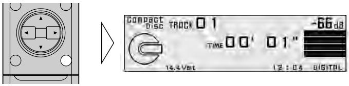
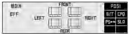
When the cover is closed
Closing the cover of the remote control makes the menu display to the closed state.
Menu display in closed state
Example: Main menu screen
Note:
- Menu display in closed state: Current mode and functions which are ON are displayed.
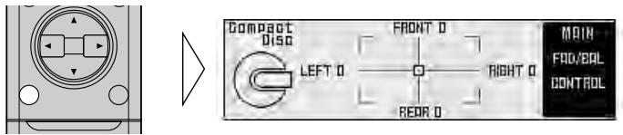
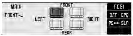
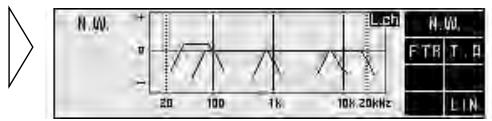
When the cover is open
Opening the cover of the remote control makes the menu display to the open state.
Menu display in open state
Example: Main menu setting screen
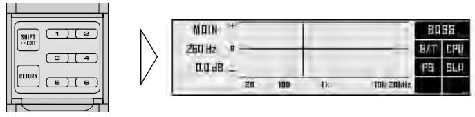
Note:
- Positions of menu items on the display correspond to the positions of FUNCTION buttons 1 to 6.
- Menu display in open state: Using FUNCTION buttons 1 to 6, operable functions are displayed.
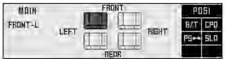
When the cover is closed in the middle of operation
- Closing the cover during operation releases the previous operation and returns the menu display to the closed mode.

If you want to dispose this product, do not mix it with general household waste. There is a separate collection system for used electronic products in accordance with legislation that requires proper treatment, recovery and recycling.
Private households in the 25 member states of the EU, in Switzerland and Norway may return their used electronic products free of charge to designated collection facilities or to a retailer (if you purchase a similar new one).
For countries not mentioned above, please contact your local authorities for the correct method of disposal.
By doing so you will ensure that your disposed product undergoes the necessary treatment, recovery and recycling and thus prevent potential negative effects on the environment and human health.
About this unit
This unit is universal digital preamp which can be operated with the combined head unit RS-D7RII (sold separately). You can operate a number of audio adjustment functions with separately sold head unit.
CAUTION:
- Do not allow this unit to come into contact with liquids. Electrical shock could result. Also, this unit damage, smoke, and overheat could result from contact with liquids.
- Keep this manual handy as a reference for operating procedures and precautions.
- Always keep the volume low enough so that you can hear sounds from outside the vehicle.
- Protect this unit from moisture.
- If the battery is disconnected or discharged, the preset memory will be erased and must be reprogrammed.
About this manual
This unit features a number of sophisticated functions ensuring superior reception and operation. All the functions have been designed for the easiest possible use, but many are not self-explanatory. This operation manual will help you benefit fully from this unit's potential and to maximize your listening enjoyment.
We recommend that you familiarize yourself with the functions and their operation by reading the manual before you begin using this unit. It is especially important that you read and observe WARNINGS and CAUTIONS in this manual.
This manual mainly explains the remote control operation. Some functions can be operated with the head unit, however, the remote control offers a number of buttons such as SHIFT, MENU, RETURN and FUNCTION buttons 1 to 6 which are not provided on the head unit. And all of audio adjustment operations can only be conducted with the remote control.
In case of trouble
Should this product fail to operate properly, contact your dealer or nearest authorized Pioneer Service Station.
Product registration
Visit us at the following site:

- Register your product. We will keep the details of your purchase on file to help you refer to this information in the event of an insurance claim such as loss or theft.
About the digital network
A vehicle, unlike the home audio, imposes several constraints upon the quality of reproduced sound, and have the following effects:
- Reflected sounds have strong effects on direct sounds because of the confined space and complex shape within a vehicle. This disturbs frequency characteristics and significantly reduces sound quality.
- The orientation of the sound image becomes unnatural, because speakers may not be installed symmetrically to left and right of the listener, or because speakers are installed in both the front and rear.
This system is equipped with a wide variety of functions that use DSP to create the ideal sound quality and sound image in a vehicle and overcome these constraints on reverberation.
Resetting the microprocessor
The microprocessor must be reset under the following conditions:
- When using this unit for the first time after installation.
- When the machine fails to operate properly.
- When strange (incorrect) messages appear on the display.
1. Remove the covering.
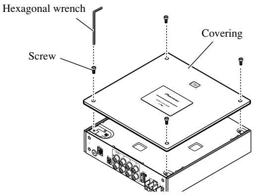
2. Press the RESET button on this unit with a supplied hexagonal wrench.
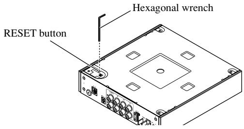
3. Replace the cover to assure the reset button is not accidentally pressed.
The cover may be attached vertically or horizontally.
Audio menu
This system has the following three audio menus:
Main (page 12)
This carries out balance adjustments as well as bass/treble adjustment, the basis for sound quality adjustments. It also sets up and adjusts the position selector, which corrects the orientation of the sound image for the listener's position in the vehicle.
Equalizer (page 20)
This corrects complex frequency disturbance in a vehicle.
The equalizer function for the component can make fine adjustments of sound quality for each frequency.
Network (page 30)
This adjusts the reproduced frequency band (cross-over frequency) and the level of each sound range (band) when a multi-amp system is set up. It also corrects unnatural orientation of the sound image caused by the locations of the speakers (using the time alignment function), by setting up a delay (time difference) between speakers set up for different sound ranges.
Note:
- The ▲/▼/◄/► buttons on the head unit (RS-D7RII) can not be used for audio adjustment operations.
Switching to the audio menu
When the system is ON, you can adjust the sound quality.
1. Each press of MENU button selects the desired audio menu in the following order:
Main (main menu) → Equalizer (equalizer menu) → Network (network menu)
2. Operate the mode.
3. Press the BAND button and cancel the audio menu.
Cancel the audio menu to return to the operations screen of the source currently in use.
Main menu
With this menu, you can make the following adjustments.
• Balance adjustment
- Bass/treble adjustment (Open state)
• Using the compression
- Listening position adjustment
- Source level adjustment
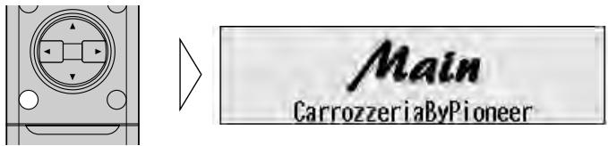
Switching to the main menu
- Press the MENU button and select the main menu.
After the title screen, the display switches to the operation screen of the main menu. Opening and closing the cover of the remote control (refer to page 5) switches between the open and closed states of the menu display and setting screen.
- To cancel the main menu, press the BAND button.
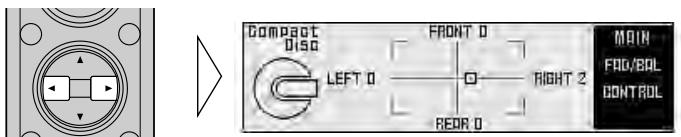
Balance adjustment (Closed state)
This function allows you to select a balance setting that provides ideal listening conditions in all occupied seats. This function can be operated with the remote control cover closed.
- Close the cover of the remote control (refer to page 5).
- Adjust left/right speaker balance with the ◀/▶ buttons.
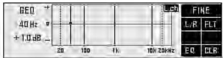
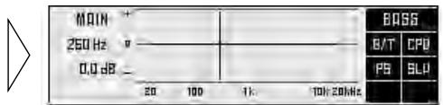
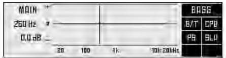
Bass/treble adjustment (Open state)
It is possible to select one from a choice of four frequencies to become the reference when adjusting the bass/treble tone. The frequencies and level adjustment ranges from which selections may be made are as follows:
Bass : 63 Hz, 100 Hz, 160 Hz, 250 Hz
Treble: 4 kHz, 6.3 kHz, 10 kHz, 16 kHz
Level adjustment range: -12 dB to +12 dB (1 dB/1 step)
1. Open the cover of the remote control (refer to page 5).
This switches to main menu setting screen.
2. Press the FUNCTION button 1.
The display switches to bass/treble adjustment screen.


3. Press the FUNCTION button 1 again to choose bass (BASS) or treble (TREB).
Pressing the button switches bass/treble.

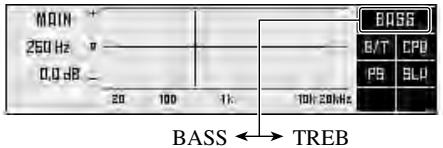
4. Press the ◀/▶ buttons and select a frequency point.
Tune to the desired frequency point.

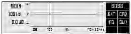
5. Press the ▲/▼ buttons and adjust the level.
Holding down these buttons continues their operations (with one stop at the central position).

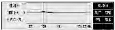
Note:
- Raising the bass/treble level too high may result in distortion. Perform bass/treble adjustment to adjust overall sound quality.
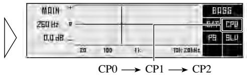
Using the compression (Open state)
You can reduce the difference between the volume levels of loud and quiet sounds. The compression function suppresses loud sounds and boosts quiet sounds to reduce the difference between the volume levels of loud and quiet sounds. It is convenient to use this function when you want to hear quiet sounds more clearly.
- CP2 (compression 2) has a larger effect than CP1 (compression 1).
1. Open the cover of the remote control (refer to page 5).
This switches to main menu setting screen.
2. Press the FUNCTION button 2 to select the setting.
Pressing the button switches the mode in the following order :
$$ \mathrm{CP0} \rightarrow \mathrm{CP1} \rightarrow \mathrm{CP2} $$
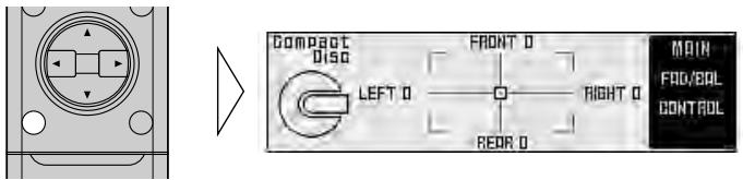
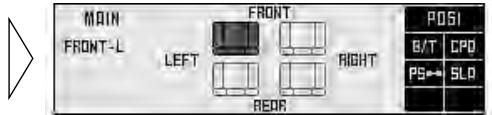
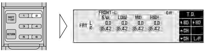
Adjusting the listening position (Open state)
One way to assure a more natural sound is to clearly position the stereo sound image (putting you in the center of the sound field).
The position selector function adjusts distance and volume level of sound from each speaker to match seat positions and the number of people in the car, and lets you recall settings at the touch of a button. The result is a natural sound regardless of the seat you are sitting in.
| Button | Position |
| ▲ | FRONT (Front seat left & right) |
| ◀ | FRONT-L (Front seat left) |
| ▶ | FRONT-R (Front seat right) |
Using the position selector
1. Open the cover of the remote control in the main menu (refer to page 5).
This switches to main menu setting screen.
2. Press the FUNCTION button 3.
The display switches to position selector screen.

3. Press the FUNCTION button 3 again to turn the position selector function ON.

4. Press one of buttons ◀/▶/▲ and select the desired position.
Set up the position to match the position of the listener in the car.

Experimenting with other positions
- The position is normally designed to match the listener's position in the car. However, other positions may prove to be more effective, depending on the model of the car and the location of the speakers. Compare the sound and choose the position in which the sounds are most natural.
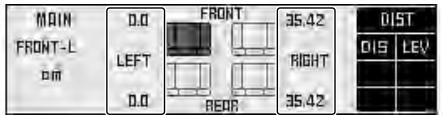
Fine tuning the position
You can finely adjust the differences in distance and sound levels for the position selected with the position selector function. Make adjustments using both methods to match the location of the speakers and the shape of your vehicle until you achieve more natural sound imaging.
Difference in distance adjustment range: 0.0 cm to 192.5 cm (0.77 cm/1 step)
The larger the difference in distance, the sooner sound from the speaker reaches your ears, so the speaker seems to move closer. Consequently, the sound image moves in the direction in which the value for the difference in distance is larger.
Adjustment range in the difference in sound levels (LEV): 0 dB to -30 dB (0.5 dB/1 step)
The smaller the level, the lower the sound volume output from the speaker, giving the listener the feeling that the speaker is moving further away. The sound image thus moves in the direction in which the value for the difference in sound levels is closer to 0.
Note:
- Fine tuning can be conducted separately for each position.
- The values set after fine tuning are stored into memory as the values for the position. When the position is next called up, the fine tuning values are recalled.
1. Use the position selector function and select the position.
Example: When selecting FRONT-L
2. Press the FUNCTION button 3 for two seconds and switch to position fine tuning screen.
3. Press FUNCTION button 1 or 2, and select to adjust difference in distance or difference in sound levels.
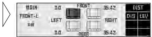
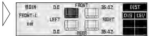
4. Press the ◀/▶ buttons to correct the position of the sound image.
Holding down these buttons continues their operations (during the difference in distance tuning, holding down the button moves the distance 1.54 cm/1 step).

5. After tuning has been completed, press the RETURN button to cancel the position fine tuning screen.
The values are stored in memory and the display returns to position selector screen.
Points concerning fine tuning
- While listening to vocals, adjust the distance to position the vocal sound image naturally to the front.
Effective distance adjustment using the position fine tuning function
— Relation to time alignment adjustment function —
The distance between the listening position and each speaker can be tuned using either of two methods.
Time alignment adjustment function of the network menu (page 32)
The distance between the listening position and each speaker of each band (high, mid, low and subwoofer) can be adjusted for the left and right speakers.
Adjustment of difference in distance with the position fine tuning function
Overall adjustment is performed for left and right speakers regardless of the band. The same adjustments are made for high, midrange, low and subwoofer bands.
Combine the two methods to ensure the position of the sound images are set up more effectively.
- Adjust the distance from each speaker using the time alignment adjustment function of the network menu (refer to page 32).
- Adjust the overall distance balance between the left and right speakers using the position fine tuning function.
Use the set values for the time alignment adjustment function to fine tune the overall balance of the sound image positions.
- Use the position fine tuning function to adjust the overall level balance between the left and right speakers.
Adjust the difference in sound levels between the left and right speakers so that the sound image is in the front.
When you have made adjustments for difference in distance using the position fine tuning function
- After adjusting the difference in distance with the position fine tuning function and switching to the time alignment adjustment screen, the values set using the position fine tuning function are added to the values previously set using the time alignment function and the sum values are displayed.
- If you want to store the displayed values in memory as new values for the time alignment function (standard values for the position fine tuning function), adjust any on value again by pressing the
▲/▼ buttons. The displayed values are stored in memory and the difference in distance set with the position fine tuning function is reset and returned to 0.
When the distance has been using the time alignment adjustment function
- Adjustment of the difference in distance using the position fine tuning function is based on time alignment adjustment delay time. When you have set a delay time using the time alignment adjustment function, since the standard value is changed, the difference in distance set using the position fine tuning function is reset and returned to 0.
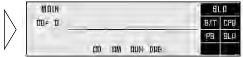
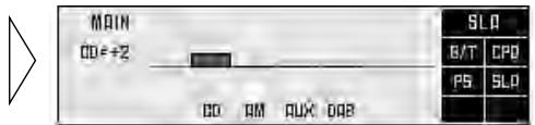
Source level adjustment (Open state)
The SLA (source level adjustment) function prevents radical leaps in volume level when switching between sources. Settings are based on the FM volume level, which remains unchanged.
- Compare the FM volume with the volume of the other source (refer to RS-D7RII (sold separately) owner's manual).
- Press the MENU button to switch to the main menu.
- Open the cover of the remote control switches to main menu setting screen.
- Press FUNCTION button 4 on main menu setting screen.
The display switches to SLA adjustment screen.
- Increase or decrease the level with the ▲/▼ buttons.
The display shows “+4” to “-4”.
- Since the FM volume is the control, SLA is not possible in the FM modes.
- The MW/LW volume level, which is different from the FM base setting volume level, can also be adjusted similar to sources other than tuner.
- The head unit's CD player, Multi-CD player and DVD player are set to the same volume adjustment setting automatically.
- AUX, External 1 and External 2 are set to the same volume adjustment setting automatically.
About the equalizer menu
One important factor for creating quality sound is the correction of disturbances in frequency characteristics within the complex shape of a vehicle interior.
Reflected sounds have a strong effect on direct sound in a vehicle because of the vehicle's shape, the confined space, absorption of sound by the seats and reflection from the windows. All these cause disturbances in the frequency characteristics. Such disturbances will be apparent as reduced sound quality.
Any one of two kinds of digital equalizer is used under this system, depending upon the configuration of the audio system. The digital equalizer adjustment corrects disturbances in frequency characteristics and creates a smooth sound quality.
- As installation conditions differ for the left and right speakers, different corrections must be made for each. All two digital equalizers are able to correct the left and right speakers separately.
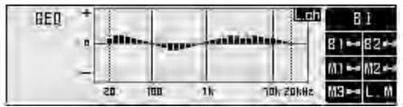
31 band graphic equalizer (31B-GEQ)
You can perform 31-band (1/3 octave intervals) level adjustments for left and right channels independently or combined to achieve the optimum acoustic characteristics for the environment in your vehicle.
3 band parametric equalizer (3B-PEQ)
You can perform 3-band level adjustments for left and right channels independently or combined, adjusting the levels of a choice of 31 frequencies (1/3 octave intervals) as desired. You can also adjust the inclination of the equalizer curve (Q factor) of each of the bands.
Equalizer menu
With this menu, you can make the following adjustments.
- Recalling the equalizer curve (Closed state) (Refer to page 45.)
- Adjusting the 31 band graphic equalizer
(Open state) - Adjusting the 3 band parametric equalizer
(Open state) - Flat function
(Open state)
• Clear function(Open state) - Memory functions of adjusted equalizer curves (Open state) (Refer to page 42.)
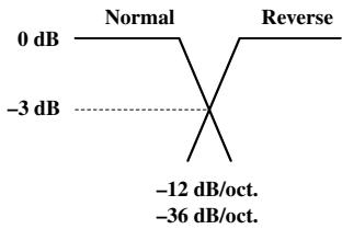
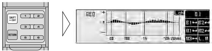
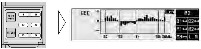
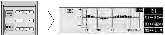
Switching to the equalizer menu
- Press the MENU button and select the equalizer menu (refer to page 11).
natural_image
Pure electrical circuit lines without any symbols▶
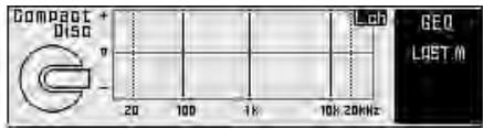
After the title screen, the display switches to the operation screen of the equalizer menu. Opening and closing the cover of the remote control (refer to page 5) switches between the open and closed states of the menu display and setting screen.
- To cancel the equalizer menu, press the BAND button.
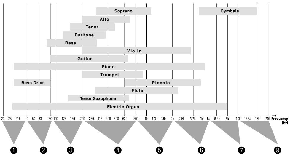
Relation between frequency characteristics and sound quality
Sound quality generally has the following characteristics, depending on the frequency.
Refer to these characteristics when making adjustments.
bar
| Instrument | Frequency (Hz) | | :--- | :--- | | Cymbals | 16000 | | Soprano | 1000 | | Alto | 750 | | Tenor | 450 | | Baritone | 350 | | Bass | 250 | | Violin | 3200 | | Guitar | 850 | | Piano | 4500 | | Trumpet | 900 | | Piccolo | 4000 | | Flute | 2500 | | Tenor Saxophone | 650 | | Electric Organ | 8000 | Bass Drum | 800 | ① ② ③ ④ ⑤ ⑥ ⑦ ⑧① This sound range feels almost like pressure on the ears of the listener, particularly if the sound is too strong.
② In this range, the listener feels the heavy bass. This is also the range in which the impact of the sound is felt in the body. Excessive sound in this range will impair the clarity of the overall sound.
③ The sound range required for bass. A lack of sound in this range results in a weak bass impact, while excessive sound will muffle the overall sound. A clear reproduction lends depth to the overall sound.
④ This is the sound range in which the sound signals are most dense and where the sound outline is created. A lack of sound in this range results in a lack of warmth. Excessive sound dims clarity.
⑤ The sound range required for the core of the sound. A lack of sound in this range weakens the core. An important range for keeping the overall sound quality in balance.
⑥ In this range, the sharp, expansive sounds of the brass and electric guitar are felt. However, excessive sound in this range is tiring on the ears.
⑦ This sound range adds color and gaiety to the overall sound. A lack in sound in this range will result in a muffled overall sound, while excessive sound will enhance the metallic aspects.
⑧ This range is required for the glamorous sound of the cymbals. However, this range does not contain the basic frequencies of almost all the instruments. Therefore, if the sound in this range is lacking somewhat, the overall sound quality will not deteriorate markedly.
The points when adjusting the equalizer curve
- Take the recreated frequency bands of the speakers into consideration when adjusting. For example, when a speaker with a band between 80 Hz and 4 kHz is connected, adjusting the level in 50 Hz or 10 kHz will have no effect.
- Balancing the bass and treble is recommended. The bass tends to be lacking when no subwoofer is connected. Adjust the treble to a lower volume to match the weaker bass and create a well-balanced sound.
- Noises coming from the road make the bass seem weak while driving. If the level is below 100Hz , adjust to a slightly greater level to maintain superb sound balance while driving.
- When the sound is inadequate or excessive, it is recommended to set the levels after checking the frequencies of the sounds in question by changing the peripheral frequencies to the maximum or minimum.
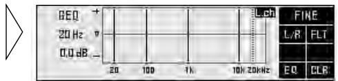
Adjusting the 31 band graphic equalizer (Open state)
Adjustable frequency : 20 Hz to 20 kHz (Every 1/3 octaves, total 31 bands)
Level adjustment range: -12 dB to +12 dB (0.5 dB/1 step)
- You can switch between the left/right combine mode and left/right independent mode at any time. So even when using the left/right independent mode, you can switch to the left/right combine mode to perform adjustments.
- Open the cover of the remote control in the equalizer menu (refer to page 5).
This switches to equalizer menu setting screen.

- Press the FUNCTION button 5 to select the 31-band graphic equalizer mode.
- Press the FUNCTION button 1 for two seconds and switch between left/right independent mode (L/R) and left/right combine mode (COM).
- Press the FUNCTION button 1 and select left or right channel. (Only for L/R mode.)
Each press the FUNCTION button 1 switches left and right channel.
Note:
- Even when using the left/right combine mode you can switch to display left and right channels, but adjustments are those performed in the left/right combine mode.
- Press the ◀/▶ buttons and select the desired band (frequency) to be adjusted.

- Press the ▲/▼ buttons and adjust the level.

- Adjust the other bands.
Repeat steps 5 and 6 to adjust to the desired sound.
- Switch between right and left to set up the equalizer curve.
Repeat steps 4 to 7 to set up equalizer curves for the left and right speakers separately.
When completing the adjustment
- It is recommended that adjustment settings be stored in memory soon after the adjustments are completed. Refer to page 42 for memory operations.
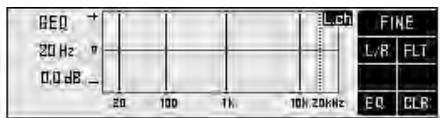
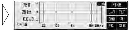
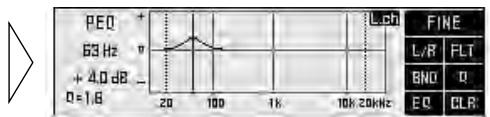
About the adjustment using the parametric equalizer
The parametric equalizer can make the following adjustments.
Separate 3 band adjustment for left/right
It is possible to set up the left and right equalizer curves separately. Among the 31 frequencies, three bands (frequencies) each can be selected to serve as the left and right central frequencies, enabling level adjustments.
Frequency point: 20 Hz to 20 kHz (Every 1/3 octave, total 31 points)
Level adjustment range: -12 dB to +12 dB (0.5 dB/1 step)
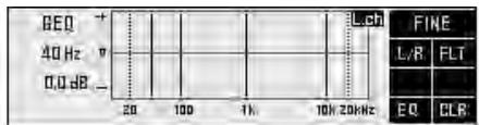
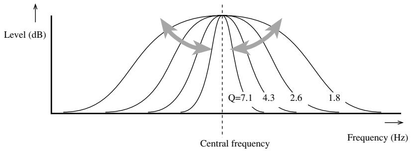
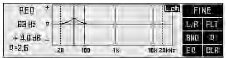
Q select function
Q factor (the inclination of the equalizer curve) in each band that serves as the central adjustment frequency can be selected separately.
Set values: 1.8, 2.6, 4.3, 7.1
The greater the value, the sharper the equalizer curve characteristics.
line
| Frequency (Hz) | Level (dB) for Q=7.1 | Level (dB) for Q=4.3 | Level (dB) for Q=2.6 | Level (dB) for Q=1.8 | | -------------- | ------------------- | ------------------- | ------------------- | ------------------- | | Q=7.1 | Peak | - | - | - | | Q=4.3 | - | - | - | - | | Q=2.6 | - | - | - | - | | Q=1.8 | - | - | - | - |Setting the equalizer curve
- You can switch between the left/right combine mode and left/right independent mode at any time. So even when using the left/right independent mode, you can switch to the left/right combine mode to perform adjustments.
- Open the cover of the remote control in the equalizer menu (refer to page 5).
This switches to equalizer menu setting screen.
- Press the FUNCTION button 5 to select the 3-band parametric equalizer mode.
- Press the FUNCTION button 1 for two seconds and switch between left/right independent mode (L/R) and left/right combine mode (COM).
- Press the FUNCTION button 1 and select left or right channel. (Only for L/R mode.)
Each press the FUNCTION button 1 switches left and right channel.
Note:
- Even when using the left/right combine mode you can switch to display left and right channels, but adjustments are those performed in the left/right combine mode.
- Press the FUNCTION button 3 and select the desired band to be adjusted.
Each press the FUNCTION button 3 switches to next band.
- Press the ◀/▶ buttons and select the desired frequency to be adjusted.
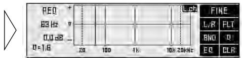
Note:
- You cannot set the intervals of the adjacent 2 bands to less than 1/3 of an octave.
- Press the ▲/▼ buttons and adjust the level.
line
| Frequency | Value | | --------- | ----- | | 0 | 1.8 | | 20 | + | | 100 | Peak | | 1K | - | | 10K | - | | 20K | - |8. Press the FUNCTION button 4 and adjust the Q factor (inclination of equalizer curve).
Press the button to change the values in the following order. Set up the desired Q factor :
$$ 1. 8 \rightarrow 2. 6 \rightarrow 4. 3 \rightarrow 7. 1 $$

line
| Frequency | Value | |---|---| | 20 | 1.0 | | 100 | 1.5 | | 1K | 1.0 | | 10K | 1.0 | | 20kHz | 1.0 | FINE L/R FLT BNO R EQ CLR9. Adjust other bands.
Repeat steps 5 to 8 to adjust the desired sound.
10. Switch between left and right to set up the equalizer curve.
Repeat steps 4 to 9 to set up the equalizer curves for the left and right speakers separately.
A convenient way to set up equalizer curves
- Store in the base memory, an equalizer curve, set in such a manner that the sound field in the car becomes flat, and adjusted to the frequency characteristics unique to your car. (It is recommended that adjustments be made after the dealer has taken measurements.) After recalling the base memory, making adjustments to suit your preference allows rapid creation of a well-balanced curve. See page 42 for memory operation.
Checking the equalizer effects
- Use the flat function to make the adjustment while confirming the effects. (See page 28.)
Equalizer adjustment for the subwoofer
- The equalizer adjustment for the subwoofer is conducted in front (when the subwoofer is connected to the front output, adjusting the rear has no effect).
On completing adjustment
- Storing the equalizer curves into memory soon after completing adjustment is recommended. See page 42 for memory operations.
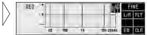
The flat function (Open state)
— Common to 31B-GEQ and 3B-PEQ —
The adjusted equalizer curve can be temporarily returned to its prior status before making the adjustment (all levels are 0 dB), using the flat function.
This is convenient for checking the effects of the adjusted equalizer curve.
1. Open the cover of the remote control in the equalizer menu (refer to page 5).
This switches to equalizer menu setting screen.
2. Press the FUNCTION button 2 switches the flat function ON/OFF.
“FLT” is displayed when the flat function is ON.
Note:
- Pressing FUNCTION button 2 for 2 seconds or more lets you make the equalizer curve for the currently selected mode flat. When in the left/right independent mode, the equalizer curves for the left and right channels are made flat independently.
- When the flat function is ON, the equalizer adjustment or memory operations of the equalizer curve can not be conducted.
— Common to 31B-GEQ and 3B-PEQ —
The clear function lets you clear the equalizer curve currently being adjusted to return it to its initial status (when all levels are 0 dB). This is convenient when you want to readjust an equalizer curve.
1. Open the cover of the remote control in the equalizer menu (refer to page 5).
This switches to equalizer menu setting screen.
2. Press the FUNCTION button 6 for two seconds to clear the equalizer curve.
Note:
- The clear function operates separately for the 31-band graphic equalizer and the 3-band parametric equalizer.
- The clear function simultaneously switches ON for left and right equalizer curves. (It cannot be used to clear just the left or right channel.)
What is the multi-amp system?
The multi-speaker system reproduces each frequency band (high, mid, low and ultrabass-ranges) through its own exclusive speaker unit. The multi-amp system provides an exclusive power amplifier for each speaker unit.
There is only limited space in a vehicle for installing speakers, and it is difficult to install large-diameter speakers in a door or on the dashboard and get high sound quality. To overcome this problem, tweeters (high-range) are sometimes installed in the dashboard in order to move the sound image upwards, or the subwoofers are installed in the rear tray in order to improve bass and ultrabass reproduction. Thus, using a multi-speaker system can correct imbalances in the sound image and significantly improve the total sound quality.
The multi-amp system offers the following features, allowing direct operation of the exclusive speaker unit for each frequency range by an exclusive power amplifier.
- It is possible to reduce the modulation distortion rate since high-range signals are not effected by strong signals in the low range.
- As it is possible to select amplifiers and speakers to suit the characteristics of each frequency range, the load on each unit is reduced, ensuring optimum performance.
Under the multi-amp system, it is necessary to divide the audio signals into each frequency range (band) and strictly control the set up conditions, using the network.
Under this system, the audio unit incorporates a network. The following adjustments can be conducted within the vehicle.
• Time alignment adjustment function
: adjusts for the difference in the distance between the listener and each speaker unit.
- Filter function
: sets up a low pass filter and high pass filter to decide the reproduced frequency band, the level and the phase of each speaker unit.
As the audio signals are processed in the form of digital signals when the network is working, the sound characteristics that best fit the vehicle interior may be created without any deterioration in sound quality.
With this menu, you can make the following adjustments.
• Time alignment adjustment
• Filter adjustment
- Switching between linear phase characteristics/minimum delay phase characteristics (LIN) (Open state)
- Memory functions of adjusted network (Open state) (Refer to page 42.)
Switching to the network menu
- Press the MENU button and select the network menu (refer to page 11).
After the title screen, the display switches to the operation screen of the network menu. Opening and closing the cover of the remote control (refer to page 5) switches between the open and closed states of the menu display and setting screen.
- To cancel the network menu, press the BAND button.
If adjustments are difficult
- Adjusting the network requires technical skills and knowledge of the amplifiers and speakers installed in the system. Consult your dealer from which the products were purchased if adjustments are difficult.
- When adjustments have already been made at your dealer, the optimum setup for vehicle's particular interior has already been installed in the memory. In this case, recall the corresponding memory for use (refer to page 45).
When completing the adjustment
- It is recommended that adjustment settings be stored in memory soon after the adjustments are completed. Refer to page 42 for memory operations.
- After completing the network adjustments, adjust the overall balance of the sound image by using the position fine tuning function of the main menu as necessary (refer to page 16).
Time alignment adjustment (Open state)
In the vehicle, the different speaker units are at widely differing distances from the listener. The sounds from the speakers therefore reach the listener at different times. When a multi-amp system is set up, this causes different delays for each frequency band (high, mid, low and ultrabass-ranges), marring the position of the sound image and the overall balance and disturbing the frequency characteristics.
The time alignment adjustment function is able to synchronize the arrival times of the different sounds by delaying the output of signals from the closest speaker units.
Switching to the time alignment adjustment mode
1. Open the cover of the remote control in the network menu (refer to page 5).
This switches to network menu setting screen.
2. Press the FUNCTION button 2.
The display switches to time alignment adjustment screen, allowing time alignment adjustment.
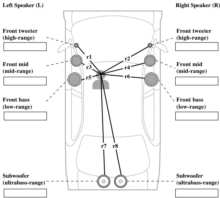
Measuring the distance to be corrected (Delay Time)
It is necessary to calculate the delay time to correct the time differences between speaker units. In order to adjust the time alignment adjustment function more easily, this system allows the delay time to be set up by simply inputting the difference in the distance between speaker units (the distance to be corrected). (The delay time will be automatically calculated by this system.)
Although the distance from each speaker unit varies depending on the position of the listener, the first set up is made for the driver's seat. If the set up has been made for the driver's seat, the optimum delay time for the listener's position can be set up by simply switching the position selector function (refer to page 15) to the listening position. (This system automatically calculates and sets up the optimum delay time for each position.)
Example: making corrections for the driver's seat in a left-hand drive vehicle
- Measure the distance between the head of the listener, when sitting in the driver's seat, and each speaker unit.
Note:
- The unit of distance must be centimeters.
Note:
- It is recommended that the boxes be filled in as the measurements are made, as this information may prove useful at a later date.
- Measure the distances to be corrected in the same manner for other systems than those used in the above example.
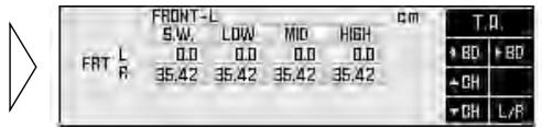
Inputting the distance to be corrected (Delay Time)
Scope of adjustment: 0 cm to 192.5 cm (0.77 cm/1 step)
(S.W.: 0 cm to 385 cm (1.54 cm/1 step))
- Open the cover of the remote control in the network menu (refer to page 5).
This switches to network menu setting screen.
- Press the FUNCTION button 2.
The display switches to time alignment adjustment screen, allowing time alignment adjustment.
- Press the FUNCTION button 6 and select the driver's seat (position).
Press the buttons to switch between “FRONT-R” and “FRONT-L”. Select the position when measuring the distance to be corrected as shown on the page 33.
Note:
- The correct distance can not be input unless these operations are conducted.
- Press FUNCTION buttons 3 or 5 and select the speaker channel to input.
Press the buttons to switch between left (L) and right (R).
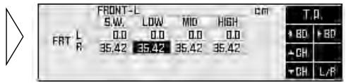
- Press FUNCTION buttons 1 or 2 and select the band to input.
Each press of the FUNCTION buttons 1 or 2 select the desired band in the following order:
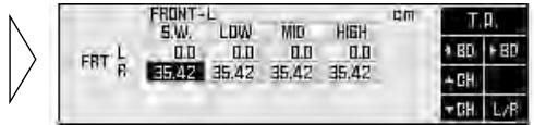
S.W. (ultrabass-range) LOW (low-range) MID (mid-range) HIGH (high-range)
6. Press the ▲/▼ buttons to input the distance to be corrected (delay time).
Input the distance to be corrected, as measured on page 33. Holding down these buttons continues their operations (during distance tuning, holding down the button moves the distance 1.54 cm/1 step).

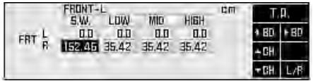
7. Carry out time alignment adjustments for the other speaker units.
Repeat steps 4 to 6 to input the distance to be corrected for each speaker unit.
Note:
- Some systems may indicate values for speaker units which are not connected. Verify the composition of the system in order to correctly adjust the bands for the connected speaker units.
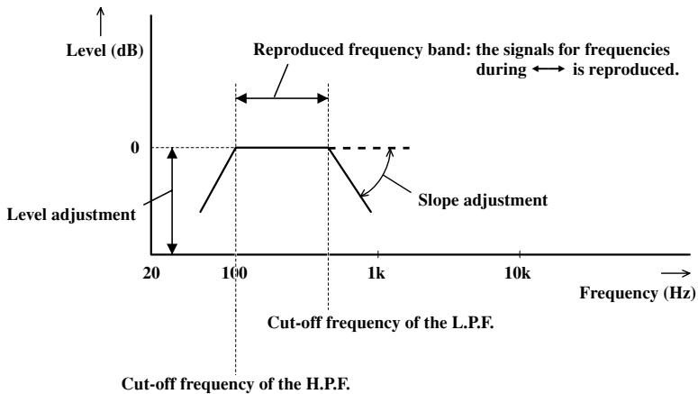
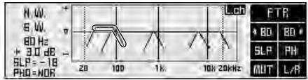
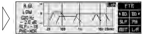
Filter adjustment (Open state)
The following adjustments can be made during filter adjustments. Make the appropriate adjustments for the reproduced frequency band and characteristics of the connected speaker unit.
Filter frequency adjustment: Every 1/3 octave
Level adjustment: 0.5 dB/1 step
The cut-off frequencies of the high pass filter (H.P.F.) and the low pass filter (L.P.F.) of each band (subwoofer, low, mid, high) and the reproduction level of each band are set up.
| Range | Cut-off frequency of H.P.F. | Cut-off frequency of L.P.F. | Level adjustment range |
| Subwoofer-range | 20 Hz to 100 Hz | 40 Hz to 250 Hz | -24 dB to +10 dB |
| Low-range | 25 Hz to 250 Hz | 250 Hz to 10 kHz | -24 dB to 0 dB |
| Mid-range | 160 Hz to 10 kHz | 2 kHz to 20 kHz | -24 dB to 0 dB |
| High-range | 1.6 kHz to 20 kHz | 8 kHz to 20 kHz | -24 dB to 0 dB |
Slope adjustment: PASS, -6, -12, -18, -24, -36, -48, -72 dB/oct.
(Every -6 dB/oct. steps)
The slope (inclination of attenuation of filter characteristics) of H.P.F. and L.P.F. is set up.
Note:
- When the slope is set as PASS, the audio signals bypass the filter circuit, cutting out the effect of the filter circuit.
- In order to protect the speaker unit, H.P.F. has no PASS set up for high ranges.
line
| Frequency (Hz) | Level adjustment (dB) | | -------------- | --------------------- | | 20 | - | | 100 | 0 | | 1k | - |About the H.P.F. and L.P.F.
High pass filter eliminates lower sound ranges (low-range) from the set up frequencies and allows high ranges through.
Low pass filter eliminates upper sound ranges (high-range) from the set up frequencies and allows low ranges through.
About the slope
This value indicates how many dB the signals attenuate when the frequency increases (or decreases) 1 octave (unit: dB/oct.). Increasing the degree of the slope increases the degree of signal attenuation.
Note:
- Setting the slope of H.P.F. and L.P.F. of the low-range as PASS creates a full range setup.
Switching to the filter adjustment mode
1. Open the cover of the remote control in the network menu (refer to page 5).
This switches to network menu setting screen.
2. Press FUNCTION button 1 on network menu setting screen.
The display switches to filter adjustment screen, allowing filter adjustments.
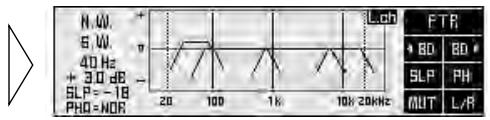
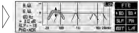
Using the mute function (MUT)
It is possible to turn the mute function ON/OFF for each band. Turning ON the mute function stops the sound output for that band. Adjust the filter while turning the mute function ON/OFF as necessary.
1. Select the band for which the mute function is to be turned ON.
To select a band, consult “Adjusting the filter” on the following page.
2. Press FUNCTION button 5 switches the mute function ON/OFF.
When muting is turned ON the filter curve displayed disappears from the display.
Before making filter adjustments
- When the position is set up for the driver's seat after adjusting the distance between the listening position and each speaker of the time alignment adjustment function (refer to page 32), it is recommended that filter adjustments be made.
- Store the different filter characteristics into memory, by the listening position set up with the position selector function (refer to page 15) or by the source being listened, and switch when necessary. Refer to page 42 for memory operations.
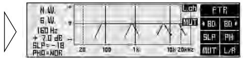
Adjusting the filter
First, determine the approximate band to be used, taking into consideration the reproduced frequency band and the characteristics of the connected speaker.
- Open the cover of the remote control in the network menu (refer to page 5).
This switches to network menu setting screen.
- Press the FUNCTION button 1.
The display switches to filter adjustment screen, allowing filter adjustments.
-
Press the FUNCTION button 6 for two seconds and switch between left/right independent mode (L/R) and left/right combine mode (COM).
-
Press FUNCTION button 6 and select left (Left) or right (Right) channel (only for L/R mode).
Each press the FUNCTION button 6 switches left and right channel.
- Even when using the left/right combine mode you can switch to display left and right channels, but adjustments are those performed in the left/right combine mode.

- Press FUNCTION buttons 1 or 2 and select the filter to be adjusted.
Press the button to switch the band to be adjusted and high pass filter/low pass filter.

- Press the ◀/▶ buttons to set up the cut-off frequency of the selected filter (crossover frequency).
Holding down these buttons continues their operations.

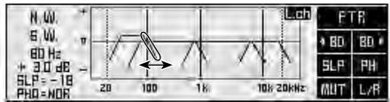
- Set up the cut-off frequencies of each filter for all the bands.
Repeat steps 5 and 6 to adjust each filter so that the band used and crossover frequency are appropriately located.
Important points in adjusting cut-off frequencies
- If the subwoofer is installed in the rear tray, setting a high cut-off frequency of L.P.F. of the subwoofer separates the bass and gives the listener the feeling that the bass is coming from behind. The L.P.F. of the subwoofer is recommended to be set at 100 Hz or below.
- Speakers used for mid and high-ranges are generally constructed to handle a limited level of input compared to low range speakers. If the cut-off frequency of H.P.F. is set lower than necessary, strong bass signals can reach the speaker and may damage it.
Important points in adjusting the level
- The low band, because of its sound frequency characteristics, incorporates the basic frequencies of many musical instruments. It is recommended that the level adjustment of the low band be made first, and then the level adjustment of the mid, high, and subwoofer be made in that order.
8. Press the ▲/▼ buttons and adjust the level of each band.
Holding down these buttons continues their operations.
Switch to each band and adjust the level in order to create a better overall balance.
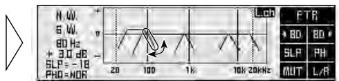
9. Press FUNCTION button 3 and adjust the slope of each filter.
Press the button to change the adjustment values.
The slope can be set up for either the high pass filter or the low pass filter. When setting up, have in mind the adjustments to be made to the next band.
10. Press FUNCTION button 4 and adjust the phase of each band.
Press the button to change between normal (NOR) and reverse (REV). Set up the one which makes the better link to the next band.
11. Switch between left and right channel to adjust the filter.
Repeat steps 4 to 10 to adjust the filters of left and right.
Important points in adjusting the slope
- A decrease in the absolute value of the slope (more gentle inclination) makes the frequency characteristics more susceptible to interference from the next band.
- Increasing the absolute value of the slope (sharper inclination) lessens the connections between bands, giving the listener the impression of hearing separate, unrelated sounds.
- Make adjustments while monitoring the link between bands by outputting all the bands as well as by outputting two neighboring bands only, using the mute function (refer to page 37).
Important points in adjusting the phase (when using minimum delay phase characteristics)
- When the values of the slope at the crossover point are set at -12dB / oct. or -36dB / oct. for both filters, the phase reverses 180^ in the cut-off frequency of the filter. In this case, setting to reverse improves the connection between sounds.
line
| Frequency | Normal (dB) | Reverse (dB) | | :--- | :--- | :--- | | -3 | 0 | 0 | | -12 | 0 | -12 | | -36 | 0 | -36 |For better frequency characteristics
- Adjusting the filter together with the equalizer function (page 20) creates a natural sound environment in the car.
Adjusting the subwoofer effectively
- Although the slope of the high pass filter is normally set as PASS, H.P.F. may sometimes reproduce clear and high quality bass rage. In this case, adjust the cut-off frequency to 20 Hz to 40 Hz and adjust the slope to -18 dB/oct. to -72 dB/oct.
- If the subwoofer is installed in the rear tray, setting up the slope of the low pass filter gently ( -6 dB/oct. , -12 dB/oct. ) gives the listener the feeling that the sound dwindles to the rear, with a resultant distortion of the forward sound image position. It is recommended to set the slope at -18 dB/oct. or more and set the cut-off frequency to 100 Hz or below.
Adjusting the low-range effectively
- When the subwoofer is connected and low-ranges are reproduced by small speaker unites such as 10 cm or less than 13 cm in diameter, setting the low-range H.P.F. as PASS may increase the distortion when strong bass signals enter. Should this occur, set up H.P.F. to avoid interference with the subwoofer.
Adjusting the high-range effectively
- Depending on the speaker units installed, bass signals for the tweeter (about 2 kHz or below) may cause distortion as the high pass filter is being adjusted. If this happens, set a sharp slope of -18 dB/oct. to -72 dB/oct. In this case, choose such settings that the mid-range and tweeter do not become separated.
- The low pass filter is generally set to PASS. However, if the ultratreble band falls harshly on the ear, it is possible to set up a more gentle slope of about -6 dB/oct.
Switching between linear phase characteristics/minimum delay phase characteristics (Open state)
This product (RS-P90) uses an FIR (finite-duration impulse response) digital filter. You can select between the filter characteristics of linear phase characteristics and minimum delay phase characteristics. This linear phase characteristics/minimum delay phase characteristics switching function enables switching to the optimum filter for a source during playback.
Linear phase characteristics (Linear phase: LIN)
A low-pass filter or high-pass filter made with a regular analog filter or IIR (infinite-duration impulse response) filter changes phase characteristics. The linear phase characteristics of this product's FIR digital filter, however, enable reproduction with natural localization and sound field without changing phase characteristics. In general, select linear phase characteristics.
Minimum delay phase characteristics (Minimum phase: MIP)
Creating precise slope characteristics with linear phase characteristics generates audio delay. As a result, during DVD playback, for example, there is a slight discrepancy between audio and video. In this case, by selecting minimum delay phase characteristics, this product's FIR digital filter minimizes audio delay to align audio and video.
Switching between linear phase characteristics/minimum delay phase characteristics
- Open the cover of the remote control in the network menu (refer to page 5).
This switches to network menu setting screen.
- Continue pressing FUNCTION button 6 for 2 seconds or more to switch between linear phase characteristics/minimum delay phase characteristics.
Each time you press the button, the setting switches between LIN (linear phase characteristics) and MIP (minimum delay phase characteristics).
Memory functions of adjusted audio menu (MEMO)
This system allows the contents of the adjusted equalizer and network to be stored in memory as follows. The numbers in ( ) represent the numbers of the memory registers to be used.
Note:
- The equalizer menu's equalizer curve, and the network menu's time alignment and filter adjustment are simultaneously stored in memory.
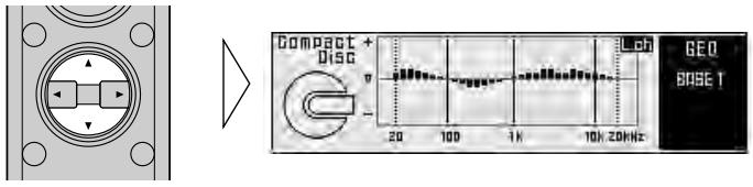
Base memory (2)
A basic memory in which is stored an equalizer curve with basic correction characteristics and adjusted network settings to assure natural acoustics that take into consideration the unique frequency characteristics of your vehicle.
Custom memory (3)
Memory for storing your customized equalizer curves and network settings.
Last memory (1)
Memory that automatically stores the last adjusted equalizer curve and network settings. You can use this, for example, to compare the sound it provides with that provided by the settings in base memory and custom memory. And even if you do not perform memory operation correctly, the last adjustments are stored in memory so you can memorize them again.
The memory operations (storing, recalling, etc.) are carried out using each menu screen. In this manual, the memory operations that are common to all the menus are illustrated mainly using the screens for a 31 band graphic equalizer. Conduct the same operations on other menus.
Note:
- Details of audio menu adjustments are stored in this product's (RS-P90) memory. If you press the RESET button of this product (RS-P90), these memorized details are cleared.
- Filter phase characteristics are also simultaneously stored in memory for extra convenience when using different sources and systems.
Memory operations are conducted in the memory mode of each audio menu.
Equalizer menu
-
Open the cover of the remote control in the equalizer menu (refer to page 5).
-
Press the SHIFT button.
The display switches to equalizer memory operation screen for conducting memory operations. Press the button again to return to the previous screen.
Note:
- This operation cannot be conducted when the flat function of the equalizer menu is ON.
Network menu
-
Open the cover of the remote control in the network menu (refer to page 5).
-
Press the SHIFT button.
The display switches to network memory operation screen for conducting memory operations. Press the button again to return to the previous screen.
Note:
- This operation cannot be conducted when the screen shows filter adjustment screen or time alignment adjustment screen.
Storing the adjustment data in memory
1. Adjust each audio menu.
Equalizer menu (page 20)
Network menu (page 30)
2. Switch to the memory mode of each menu (refer to page 43).
The display switches to memory operation screen of each menu.
line
| Time | Value | |------|-------| | 20 | + | | 100 | - | | 1h | - | | 70h | - | | 20kHz | - |3. To store in memory, press the FUNCTION button corresponding to the desired memory number for two seconds.
Note:
- When the adjustment data have been stored, the previous data are eliminated and replaced by the new.
4. Press the SHIFT button to cancel memory mode.
The display returns to the previous screen.
To avoid accidentally erasing stored data
- In order to avoid erasing stored data with new data, it is possible to set up a protect function (refer to page 47).
- Protect function ON/OFF switching is simultaneously performed for both memories. So, for example, if the protect function is switched ON for memory B1, it is switched ON for both base memory B1 and B2. Also, if the protect function is switched ON for M1, it is switched ON for both custom memory M1 and M2. However, the protect function does not operate for M3 and LM.
- If the protect function is ON, you cannot store information in that MEMORY button. Store information with another MEMORY button, or cancel the protect function. Since the protect function is cancelled after the memory to be cleared is called up, the current adjusted settings are automatically stored in last memory.
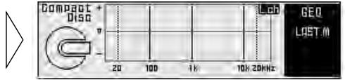
Recalling data stored in memory
There are two ways to recall data stored in memory.
In forward/reverse order — Functions of equalizer menu —
This function can be operated when the cover of the remote control is closed. Stored data can be recalled by moving forwards or backwards through the memory numbers (the numbers of the corresponding FUNCTION buttons).
Note:
- It is not possible to recall the memory in this manner when operating the network menu.
Specifying the memory number directly
This function can be operated when the cover of the remote control is open and the menu displays open state. Stored data can be retrieved directly.
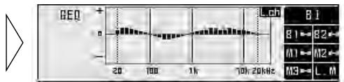
Recalling memory using forward/reverse order — Functions of equalizer menu —
1. Close the cover of the remote control.
The menu display switches to closed state.
2. Press the ▲/▼ buttons to recall the memory.
Press these buttons to move forwards or backwards through the memory numbers.
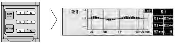
Specifying the memory number directly
- Switch to the memory mode of each menu (refer to page 43).
The display switches to memory operations screen of each menu.
line
| Time | Value | |------|-------| | 20 | 8 | | 100 | ~7 | | 1h | ~6 | | 10h | ~5 | | 20h | ~4 |- Press the FUNCTION button to recall the memory.
Press the FUNCTION button which corresponds to the desired memory number.
Memory recall operations on the equalizer menu
- When the flat function is turned ON, it is not possible to recall memory.
Memory protect function
In order to avoid accidentally erasing data which have been stored in memory, or to avoid replacing stored data, it is possible to set up a protect function for the following memory numbers.
When the protect function is ON, adjustment data storage operations are not accepted.
Note:
- Protect function ON/OFF switching is simultaneously performed for both memories. So, for example, if the protect function is switched ON for memory B1, it is switched ON for both base memory B1 and B2. Also, if the protect function is switched ON for M1, it is switched ON for both custom memory M1 and M2. However, the protect function does not operate for M3 and LM.
1. Recall the memory (refer to page 45).
Specify the memory number directly to recall the memory.
2. Press the RETURN button for two seconds to turn ON the protect function.
Press the button again for two seconds to cancel the protect function.
When turning the protect function ON/OFF
- Turning the protect function ON/OFF does not bring up anything on the display.
- When the protect function is turned ON and the user attempts to store new data in that memory, the “☐” appears to signify that data storage is not possible.
Inputting the name
Inputting the name of the person who set up the memory (equalizer and network) of the Audio menu, or messages, stores them in the RS-D7RII's head unit's memory. The RS-D7RII head unit is sold separately.
Switching to each audio menu brings up the title screen of each menu first. On this title screen of the audio menu, the stored contents are displayed.
Note:
• A maximum of 20 characters can be stored.
- The same contents are displayed on the title screen of all the audio menus.
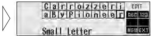
Inputting characters (Switching to the edit mode)
Characters are input in edit mode (EDIT).
1. Press the MENU button to switch to the audio menu.
It is possible to switch to edit mode from all the audio menus (main/equalizer/network). Switch to one of these menus.
(Example: Main menu)
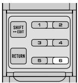
2. Open the cover of the remote control.
3. Press the SHIFT button for two seconds to switch to edit mode.
The display switches to character input screen to allow input of characters.
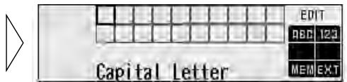
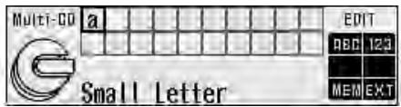
4. Switch the desired character type with FUNCTION button 1.
Each press of FUNCTION button 1 changes the character type in the following order:
Upper case alphabet (capital letter), numbers and symbols → Lower case alphabet (small letter) → European letters (european character), such as those with accents (e.g. á, à, ä, ç)

Note:
- You can select to input numbers and symbols by pressing FUNCTION button 2.
5. Select letters, numbers and symbols with the ▲/▼ buttons.
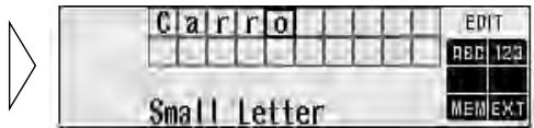
6. Move the box left and right with the ◀/▶ buttons.
To insert a space, skip the box with the ▶ button.
Continued overleaf.
- When you have completed title input, memorize by pressing the FUNCTION button 5.
- Press the FUNCTION button 6 or RETURN button and return to the previous mode.
▶
- The contents stored in memory are indicated on the display.
Switching the audio menu displays on the title screen the contents stored in memory.
natural_image
Pure electrical circuit lines without any symbols▶

When removing the car battery
- The separately sold head unit (RS-D7RII) stores the name of the person who set up the audio in memory. Removing the car battery clears the memory.
Equalizer
| Frequency | B1 | B2 | M1 | M2 | M3 | |||||
| LEFT | RIGHT | LEFT | RIGHT | LEFT | RIGHT | LEFT | RIGHT | LEFT | RIGHT | |
| 20 Hz | ||||||||||
| 25 Hz | ||||||||||
| 31.5 Hz | ||||||||||
| 40 Hz | ||||||||||
| 50 Hz | ||||||||||
| 63 Hz | ||||||||||
| 80 Hz | ||||||||||
| 100 Hz | ||||||||||
| 125 Hz | ||||||||||
| 160 Hz | ||||||||||
| 200 Hz | ||||||||||
| 250 Hz | ||||||||||
| 315 Hz | ||||||||||
| 400 Hz | ||||||||||
| 500 Hz | ||||||||||
| 630 Hz | ||||||||||
| 800 Hz | ||||||||||
| 1 kHz | ||||||||||
| 1.25 kHz | ||||||||||
| 1.6 kHz | ||||||||||
| 2 kHz | ||||||||||
| 2.5 kHz | ||||||||||
| 3.15 kHz | ||||||||||
| 4 kHz | ||||||||||
| 5 kHz | ||||||||||
| 6.3 kHz | ||||||||||
| 8 kHz | ||||||||||
| 10 kHz | ||||||||||
| 12.5 kHz | ||||||||||
| 16 kHz | ||||||||||
| 20 kHz | ||||||||||
- When using the left/right combine mode, record in the “Left (Lch)” column.
- With the 3-band parametric equalizer, input the appropriate frequency.
Network: Filter characteristics
| B1 LIN / MIP | B2 LIN / MIP | ||||||||||||
| L.P.F. | H.P.F. | Level | Phase | L.P.F. | H.P.F. | Level | Phase | ||||||
| Frequency | Slope | Frequency | Slope | Frequency | Slope | Frequency | Slope | ||||||
| LEFT | HIGH | ||||||||||||
| MID | |||||||||||||
| LOW | |||||||||||||
| S.W. | |||||||||||||
| RIGHT | HIGH | ||||||||||||
| MID | |||||||||||||
| LOW | |||||||||||||
| S.W. | |||||||||||||
| M1 LIN / MIP | M2 LIN / MIP | ||||||||||||
| L.P.F. | H.P.F. | Level | Phase | L.P.F. | H.P.F. | Level | Phase | ||||||
| Frequency | Slope | Frequency | Slope | Frequency | Slope | Frequency | Slope | ||||||
| LEFT | HIGH | ||||||||||||
| MID | |||||||||||||
| LOW | |||||||||||||
| S.W. | |||||||||||||
| RIGHT | HIGH | ||||||||||||
| MID | |||||||||||||
| LOW | |||||||||||||
| S.W. | |||||||||||||
| M3 LIN / MIP | |||||||
| L.P.F. | H.P.F. | Level | Phase | ||||
| Frequency | Slope | Frequency | Slope | ||||
| LEFT | HIGH | ||||||
| MID | |||||||
| LOW | |||||||
| S.W. | |||||||
| RIGHT | HIGH | ||||||
| MID | |||||||
| LOW | |||||||
| S.W. | |||||||
- When using the left/right combine mode, record in the “Left (Lch)” column.
Network: Time alignment
| B1 | Position: | |||
| S.W. | LOW | MID | HIGH | |
| Left (LEFT) | ||||
| Right (RIGHT) | ||||
| B2 | Position: | |||
| S.W. | LOW | MID | HIGH | |
| Left (LEFT) | ||||
| Right (RIGHT) | ||||
| M1 | Position: | |||
| S.W. | LOW | MID | HIGH | |
| Left (LEFT) | ||||
| Right (RIGHT) | ||||
| M2 | Position: | |||
| S.W. | LOW | MID | HIGH | |
| Left (LEFT) | ||||
| Right (RIGHT) | ||||
| M3 | Position: | |||
| S.W. | LOW | MID | HIGH | |
| Left (LEFT) | ||||
| Right (RIGHT) | ||||
Main: Compression
| B1 | B2 | M1 | M2 | M3 |
WARNING
- For traffic safety and to maintain safe driving conditions, keep the volume low enough so that you can still hear normal traffic sound.
- Check the connections of the power supply and speakers if the fuse of the battery wire or the amplifier fuse blows. Detect the cause and solve the problem, then replace the fuse with another one of the same size and rating.
- To prevent malfunction of the amplifier and speakers, the protective circuit will cut the power supply to the amplifier (sound will stop) when an abnormal condition occurs. In such a case, switch the power to the system OFF and check the connection of the power supply and speakers. Detect the cause and solve the problem.
- Contact the dealer if you cannot detect the cause.
- To prevent an electric shock or short-circuit during connection and installation, be sure to disconnect the negative (−) terminal of the battery beforehand.
- Confirm that no parts are behind the panel when drilling a hole for installation of this unit. Be sure to protect all cables and important equipment such as fuel lines, brake lines and the electrical wiring from damage.
CAUTION
- This unit is for vehicles with a 12-volt battery and negative grounding. Before installing it in a recreational vehicle, truck, or bus, check the battery voltage.
- To avoid shorts in the electrical system, be sure to disconnect the battery cable before beginning installation.
- Refer to the owner's manual for details on connecting the power amp and other units, then make connections correctly.
- Secure the wiring with cable clamps or adhesive tape. To protect the wiring, wrap adhesive tape around them where they lie against metal parts.
- Route and secure all wiring so it cannot touch any moving parts, such as the gear shift, handbrake, and seat rails. Do not route wiring in places that get hot, such as near the heater outlet. If the insulation of the wiring melts or gets torn, there is a danger of the wiring short-circuiting to the vehicle body.
- Don't pass the clear/red lead through a hole into the engine compartment to connect to the battery. This will damage the lead insulation and cause a very dangerous short.
-
Do not shorten any leads. If you do, the protection circuit may fail to work when it should.
-
Never feed power to other equipment by cutting the insulation of the power supply lead of the unit and tapping into the lead. The current capacity of the lead will be exceeded, causing overheating.
- When replacing a fuse, be sure to use only fuses of the rating prescribed on the fuse holder.
- The clear/black lead is ground. Please ground this lead separately from the ground of high-current products such as power amps.
If you ground the products together and the ground becomes detached, there is a risk of damage to the products or fire. - When this product's source is switched ON, a control signal is output through the blue/white lead. Connect to an external power amp's system remote control (max. 300 mA 12 V DC).
- When an external power amp is being used with this system, be sure not to connect the blue/white lead to the amp's power terminal.
- To prevent incorrect connection, the input side of the IP-BUS connector and optical connector is blue, and the output side is black. Connect the connectors of the same colors correctly.
- Cords for this product and those for other products may be different colors even if they have the same function. When connecting this product to another product, refer to the supplied manuals of both products and connect cords that have the same function.
Routing the optical cable
Note:
- Try not to bend the optical cable sharply. If it is necessary to bend it sharply, make sure that the bending radius is at least 25 mm, otherwise the cable will not transfer signals properly and so this unit will not work properly.
- Route the optical cable so that nothing heavy rests on it, and so that it cannot be stepped on or caught in anything – for instance, a door.
- Make a loop of diameter at least 200 mm with the remaining optical cable so that the cable does not get strained.
- When plugging the optical cable into the unit, use the supplied cable cramp to prevent the cables from being bent sharply.
- Route the optical cable so that it does not get caught in moving parts such as the gear shift, hand brake, or seat sliding mechanism. Keep the cable away from hot spots, such as near the heater outlet.
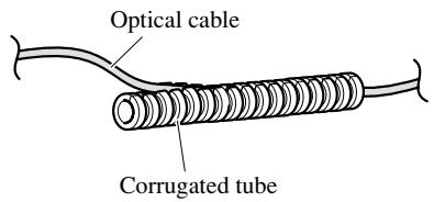
■ Using the corrugated tube
To prevent the optical cable from being strained, use the corrugated tube after cutting it to the correct length.
- Insert the optical cable into the corrugated tube.
Setting example
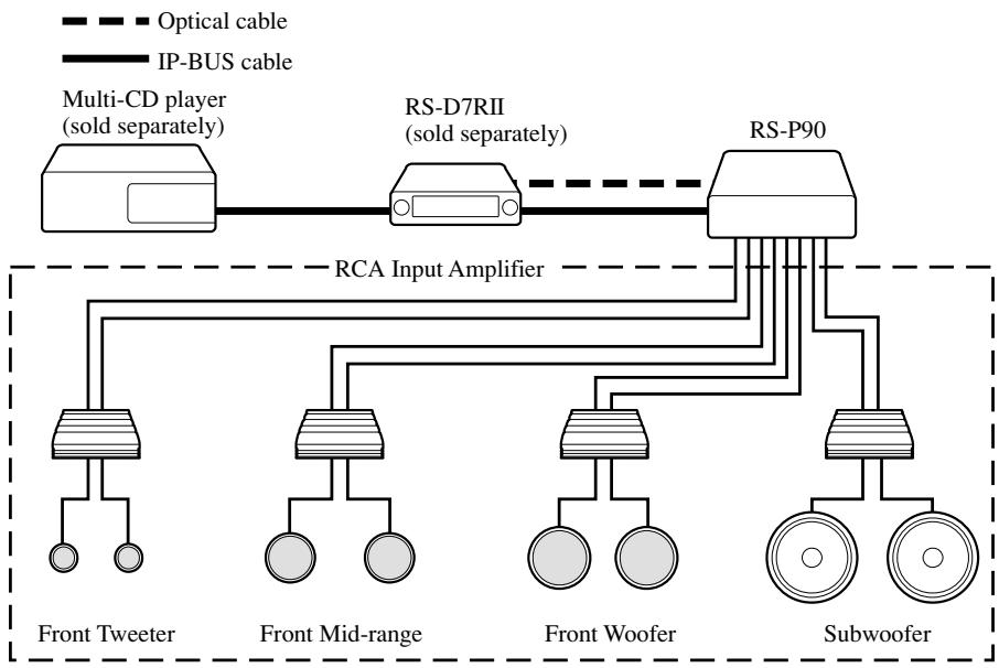
flowchart
graph TD
    A["Multi-CD player (sold separately)"] --> B["RS-D7RII (sold separately)"]
    B --> C["RS-P90"]
    D["Front Tweeter"] --> E["Front Mid-range"]
    E --> F["Front Woofer"]
    F --> G["Subwoofer"]
    H["Optical cable"] -.-> B
    I["IP-BUS cable"] -.-> B
    J["RCA Input Amplifier"] --> B
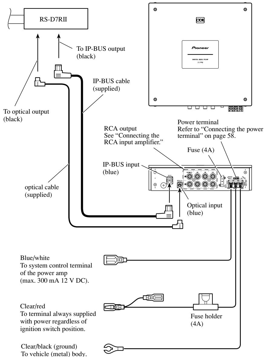
Connection diagram
flowchart
graph TD
    A["RS-D7RII"] --> B["To optical output (black)"]
    A --> C["IP-BUS cable (supplied)"]
    A --> D["Optical cable (supplied)"]
    A --> E["To IP-BUS output (black)"]
    A --> F["IP-BUS cable (supplied)"]
    G["Pioneer"] --> H["Power terminal Refer to “Connecting the power terminal” on page 58."]
    G --> I["Fuse (4A)"]
    G --> J["Optical input (blue)"]
    G --> K["Blue/white To system control terminal of the power amp (max. 300 mA 12 V DC)."]
    G --> L["Clear/red To terminal always supplied with power regardless of ignition switch position."]
    G --> M["Fuse holder (4A)"]
    G --> N["Clear/black (ground) To vehicle (metal) body."]
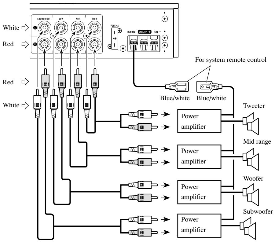
flowchart
graph TD
A["White"] --> B["SUBWOOFER"]
C["Red"] --> D["SUBWOOFER"]
E["White"] --> F["Subwoofer"]
G["Red"] --> H["Subwoofer"]
I["Blue/white"] --> J["Tweeter"]
K["Blue/white"] --> L["Mid range"]
M["Power amplifier"] --> N["Woofer"]
O["Power amplifier"] --> P["Subwoofer"]
Q["Power amplifier"] --> R["Subwoofer"]
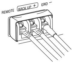
S["FUSE 4A"] --> T["REMOTE"]
U["REMO"] --> V["BACK UP"]
W["GRND"] --> X["+"]
Y["For system remote control"] --> Z["Blue/white"]
style A fill:#f9f,stroke:#333
style C fill:#f9f,stroke:#333
style E fill:#f9f,stroke:#333
style G fill:#f9f,stroke:#333
style I fill:#f9f,stroke:#333
style J fill:#ccf,stroke:#333
style L fill:#ccf,stroke:#333
style M fill:#ccf,stroke:#333
style N fill:#ccf,stroke:#333
style O fill:#ccf,stroke:#333
style P fill:#ccf,stroke:#333
style Q fill:#ccf,stroke:#333
style R fill:#ccf,stroke:#333
style S fill:#ccf,stroke:#333
style T fill:#ccf,stroke:#333
style U fill:#ccf,stroke:#333
style V fill:#ccf,stroke:#333
style W fill:#ccf,stroke:#333
Connecting the power terminal
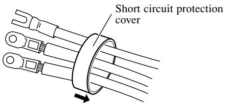
1. Put the short-circuit protection cover around the blue/white, clear/red and clear/black lead.
Be sure to use this cover to prevent short-circuit.
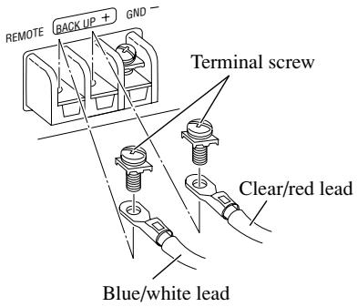
2. Connecting the leads.
Securely fasten the leads with terminal screws.

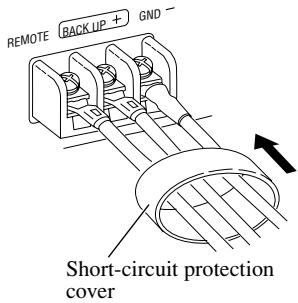
3. Cover the entire terminal with the short-circuit protection cover.
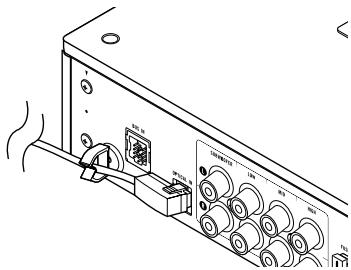
Secure the optical cable
1. Attach the cable clamp.
When plugging the optical cable into the unit, use the supplied cable clamp to prevent the cables from being bent sharply.
2. Route the optical cable through the cable clamp.
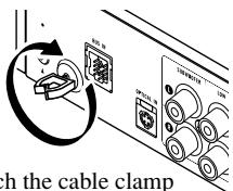
Attach the cable clamp into the hole.
natural_image
Line drawing of a vintage electronic device with multiple ports and a speaker (no text or symbols)Note:
- Before finally installing the unit, connect the wiring temporarily, making sure it is all connected up properly, and the unit and the system work properly.
- Use only the parts included with the unit to ensure proper installation. The use of unauthorized parts can cause malfunction.
- Consult with your nearest dealer if installation requires the drilling of holes or other modifications of the vehicle.
- Install the unit where it does not get in the driver's way and cannot injure the passenger if there is a sudden stop, like an emergency stop.
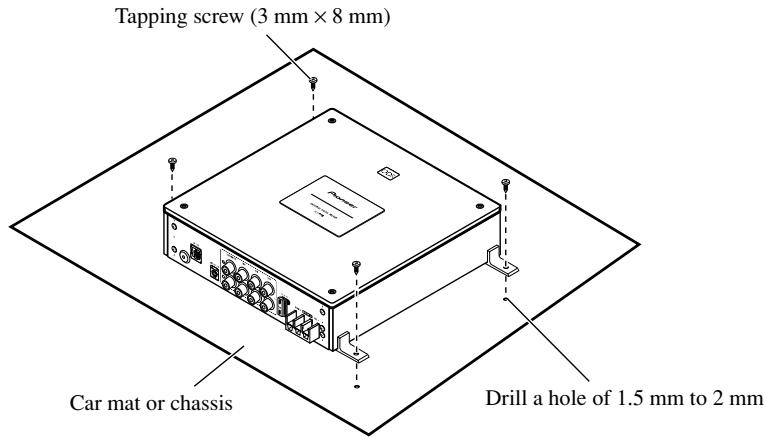
Installing the unit
1. Install the brackets to the bottom of the unit.
The brackets may also be installed vertically.
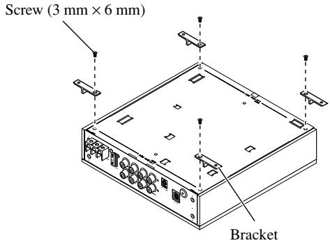
2. Install the unit to the vehicle.
When an error occurs, locate the cause according to the list below. In most cases, the problem is incorrect connections or settings.
-
Double check the connections and settings using the checklist.
-
If connections and settings are correct, press the RESET button.
Refer to “Resetting the microprocessor” on page 10.
- If the malfunction continues even after pressing the RESET button, contact your dealer or nearest authorized Pioneer Service Station.
Checklist
| Symptom | Cause | Remedy | Page |
| No Operation | The battery is not connected. | Connect the battery. | — |
| An clear/red lead is not properly connected. | Connect all clear/red leads to the battery terminal, supplied with constant power, regardless of the ignition switch position after running them through the vehicle's fuse unit. | 5658 | |
| A clear/black lead (ground) is not properly connected. | Firmly connect all the clear/black leads to the vehicle (metal) body. | 5658 | |
| A blue/white lead is not properly connected. | Connect the blue/white lead of the RCA input power amplifier to the blue/white lead of this unit. | 5657 | |
| The fuse is blown. | Remove the cause and replace with another fuse of the same rating. | 56 | |
| Incorrect connection. | Make sure all the connectors are properly connected. | 56~58 |
GENERAL
Power Source ...... DC 14.4 V (10.8 to 15.1 V allowable)
Grounding system ...... Negative type
Max. Current consumption 1 A
Fuse 4 A
Dimensions ..... 240 (W) mm × 59 (H) mm × 240 (D) mm
Weight 3.6 kg
DSP/PREAMP
Tone controls (parametric)
Bass frequency ...... 63 Hz, 100 Hz, 160 Hz, 250 Hz
Treble frequency ..... 4 kHz, 6.3 kHz, 10 kHz, 16 kHz
Gain ±12 dB
31-band graphic equalizer (L/R independent)
Frequency 20 Hz to 20 kHz, 1/3 oct.
Gain .... ±12 dB (0.5 dB)
3-band parametric equalizer (L/R independent)
Frequency 20 Hz to 20 kHz, 1/3 oct.
Gain ±12 dB (0.5 dB)
Crossover network (L/R independent)
SUBWOOFER
...... HPF frequency: 20 Hz to 100 Hz, 1/3 oct.
LPF frequency: 40 Hz to 250 Hz, 1/3 oct.
...... Gain: +10 dB to -24 dB (0.5 dB)
LOW ...... HPF frequency: 25 Hz to 250 Hz, 1/3 oct.
..... LPF frequency: 250 Hz to 10 kHz, 1/3 oct.
...... Gain: 0 dB to -24 dB (0.5 dB)
MID ...... HPF frequency: 160 Hz to 10 kHz, 1/3 oct.
LPF frequency: 2 kHz to 20 kHz, 1/3 oct.
...... Gain: 0 dB to -24 dB (0.5 dB)
HIGH
...... HPF frequency: 1.6 kHz to 20 kHz, 1/3 oct.
LPF frequency: 8 kHz to 20 kHz, 1/3 oct.
...... Gain: 0 dB to -24 dB (0.5 dB)
Slope
..... PASS, -6, -12, -18, -24, -36, -48, -72 dB/oct.
(PASS: no pass HPF-High channel)
Phase ...... NORMAL/REVERSE
Time alignment
(H/M/L ch) 0 cm to 192.5 cm (0.77 cm)
(SW ch) 0 cm to 385 cm (1.54 cm)
Position adjustment
...... DISTANCE: 0 cm to 192.5 cm (0.77 cm)
Level: 0 dB to -30 dB (0.5 dB)
Sampling frequency 44.1 kHz
Digital input ...... Optical input
Analog Output ...... RCA output (4 line)
RCA OUTPUT
Frequency response ...... 10 Hz to 20 kHz, (-1, +0 dB)
Max. output level/impedance ....4 V/220 Ω
Distortion.... 0.002% (1 kHz, 20 kHz LPF)
Signal-to-noise ratio 115 dB (IHF-A network)
Separation .... 80 dB (100 Hz to 10 kHz, 20 kHz LPF)
Note:
- Specifications and the design are subject to possible modification without notice due to improvements.
www.pioneer-eur.com
Visit www.pioneer.co.uk (or www.pioneer-eur.com) to register your product. Visite www.pioneer.es (o www.pioneer-eur.com) para registrar su producto. Zum Registrieren Ihres Produktes besuchen Sie bitte www.pioneer.de (oder www.pioneer-eur.com). Visitez www.pioneer.fr (ou www.pioneer-eur.com) pour enregistrer votre appareil. Si prega di visitare il sito www.pioneer.it (o www.pioneer-eur.com) per registrare il prodotto. Bezoek www.pioneer.nl (of www.pioneer-eur.com) om uw product te registreren. Посетите www.pioneer-rus.ru (или www.pioneer-eur.com) для регистрации приобретенного Вами изделия.
PIONEER CORPORATION
PIONEER ELECTRONICS (USA) INC.
P.O. Box 1540, Long Beach, California 90801-1540, U.S.A. TEL: (800) 421-1404
PIONEER EUROPE NV
Haven 1087, Keetberglaan 1, B-9120 Melsele, Belgium TEL: (0) 3/570.05.11
PIONEER ELECTRONICS ASIACENTRE PTE. LTD.
253 Alexandra Road, #04-01, Singapore 159936 TEL: 65-6472-7555
PIONEER ELECTRONICS AUSTRALIA PTY. LTD.
178-184 Boundary Road, Braeside, Victoria 3195, Australia TEL: (03) 9586-6300
PIONEER ELECTRONICS OF CANADA, INC.
300 Allstate Parkway, Markham, Ontario L3R OP2, Canada TEL: 1-877-283-5901
PIONEER ELECTRONICS DE MEXICO, S.A. de C.V.
Blvd.Manuel Avila Camacho 138 10 piso Col.Lomas de Chapultepec, Mexico, D.F. 11000 TEL: 55-9178-4270
先鋒股份有限公司
Published by Pioneer Corporation.
Copyright © 2006 by Pioneer Corporation.
All rights reserved.
Publication de Pioneer Corporation.
Copyright © 2006 Pioneer Corporation.