
DEH-P9200R - Car stereo PIONEER - Free user manual and instructions
Find the device manual for free DEH-P9200R PIONEER in PDF.

| Product type | Car stereo with CD player and RDS tuner |
| Brand and model | Pioneer DEH-P9200R |
| Dimensions (H x W x D) | 50 x 178 x 160 mm (approx. DIN standard) |
| Weight | Approximately 1.5 kg |
| Power supply | 12 V DC, vehicle battery (negative terminal to ground) |
| Output power | 45 W max per channel (4 channels), impedance 4-8 Ω |
| Fuse | 30 A (cartridge type, ATO) |
| Connectivity | IP-BUS input (blue), front/rear/subwoofer RCA outputs, motorized antenna |
| Audio outputs | Front, rear, subwoofer (2 V RMS, 4 V max) |
| Main features | CD player, FM/AM tuner, DFS alarm, wired remote control |
| Equalizer | Built-in sound presets (not detailed in the manual) |
| Speaker compatibility | Power handling 45 W, impedance 4-8 Ω |
| DFS alarm | Anti-theft system with door switches and alarm output (12 V, 500 mA max) |
| Installation | Front or rear DIN mounting with bracket and rubber ring |
| Maximum installation angle | 60° from horizontal |
| Operating temperature | Avoid hot places (near heater outlets) |
| Maintenance and cleaning | Clean with a soft, dry cloth; do not use chemical products |
| Spare parts and repairability | Fuse, cables, brackets; repair by authorized Pioneer technician |
Frequently Asked Questions - DEH-P9200R PIONEER
User questions about DEH-P9200R PIONEER
0 question about this device. Answer the ones you know or ask your own.
Ask a new question about this device
Download the instructions for your Car stereo in PDF format for free! Find your manual DEH-P9200R - PIONEER and take your electronic device back in hand. On this page are published all the documents necessary for the use of your device. DEH-P9200R by PIONEER.
USER MANUAL DEH-P9200R PIONEER
MANUEL D'INSTALLATION
Note:
- This unit is for vehicles with a 12-volt battery and negative grounding. Before installing it in a recreational vehicle, truck, or bus, check the battery voltage.
- To avoid shorts in the electrical system, be sure to disconnect the battery cable before beginning installation.
- Refer to the owner's manual for details on connecting the power amp and other units, then make connections correctly.
- Secure the wiring with cable clamps or adhesive tape. To protect the wiring, wrap adhesive tape around them where they lie against metal parts.
- Route and secure all wiring so it cannot touch any moving parts, such as the gear shift, handbrake, and seat rails. Do not route wiring in places that get hot, such as near the heater outlet. If the insulation of the wiring melts or gets torn, there is a danger of the wiring short-circuiting to the vehicle body.
- Don't pass the yellow lead through a hole into the engine compartment to connect to the battery. This will damage the lead insulation and cause a very dangerous short.
- Do not shorten any leads. If you do, the protection circuit may fail to work when it should.
- Never feed power to other equipment by cutting the insulation of the power supply lead of the unit and tapping into the lead. The current capacity of the lead will be exceeded, causing overheating.
- When replacing fuse, be sure to use only fuse of the rating prescribed on the fuse holder.
- Since a unique BPTL circuit is employed, never wire so the speaker leads are directly grounded or the left and right speaker leads are common.
- The black lead is ground. Please ground this lead separately from the ground of high-current products such as power amps.
If you ground the products together and the ground becomes detached, there is a risk of damage to the products or fire. - If the RCA pin jack on the unit will not be used, do not remove the caps attached to the end of the connector.
-
Speakers connected to this unit must be high-power types with minimum rating of 45 W and impedance of 4 to 8 ohms. Connecting speakers with output and/or impedance values other than those noted here may result in the speakers catching fire, emitting smoke, or becoming damaged.
-
When this product's source is switched ON, a control signal is output through the blue/white lead. Connect to an external power amp's system remote control or the car's Auto-antenna relay control terminal (max. 300mA12VDC ). If the car features a glass antenna, connect to the antenna booster power supply terminal.
- When an external power amp is being used with this system, be sure not to connect the blue/white lead to the amp's power terminal. Likewise, do not connect the blue/white lead to the power terminal of the auto-antenna. Such connection could cause excessive current drain and malfunction.
- To avoid short-circuiting, cover the disconnected lead with insulating tape. Especially, insulate the unused speaker leads without fail. There is a possibility of short-circuiting if the leads are not insulated.
- To prevent incorrect connection, the input side of the IP-BUS connector is blue, and the output side is black. Connect the connectors of the same colors correctly.
- If this unit is installed in a vehicle that does not have an ACC (accessory) position on the ignition switch, the red lead of the unit should be connected to a terminal coupled with ignition switch ON/OFF operations. If this is not done, the vehicle battery may be drained when you are away from the vehicle for several hours. (Fig. 1)
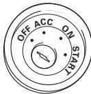
ACC position
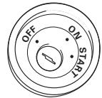
No ACC position
Fig. 1
- Cords for this product and those for other products may be different colors even if they have the same function. When connecting this product to another product, refer to the supplied Installation manuals of both products and connect cords that have the same function.
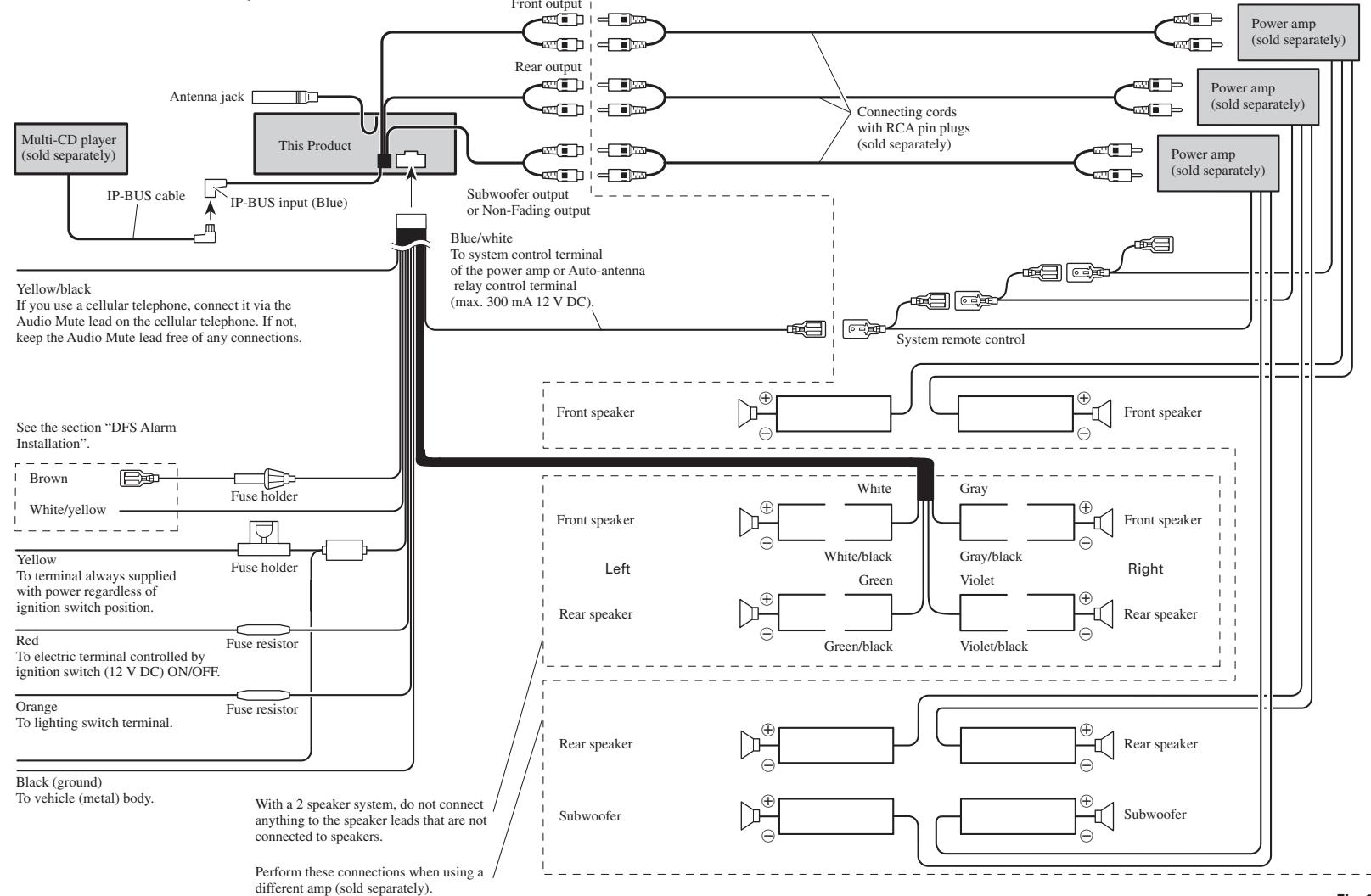
■ When not connecting a rear speaker lead to a Subwoofer
flowchart
graph TD
A["Multi-CD player (sold separately)"] --> B["IP-BUS cable"]
B --> C["IP-BUS input (Blue)"]
C --> D["Subwoofer output or Non-Fading output"]
D --> E["Front output"]
D --> F["Rear output"]
D --> G["Connecting cords with RCA pin plugs (sold separately)"]
E --> H["Power amp (sold separately)"]
F --> I["Power amp (sold separately)"]
G --> J["Power amp (sold separately)"]
K["Yellow/black<br>If you use a cellular telephone, connect it via the Audio Mute lead on the cellular telephone. If not,<br>keep the Audio Mute lead free of any connections."] --> L["See the section "DFS Alarm Installation""]
L --> M["Brown"]
L --> N["White/yellow"]
L --> O["Fuse holder"]
L --> P["Fuse holder"]
L --> Q["Fuse resistor"]
L --> R["Fuse resistor"]
L --> S["Red<br>To terminal always supplied<br>with power regardless of ignition switch position."]
L --> T["Orange<br>To lighting switch terminal."]
U["Black (ground)<br>To vehicle (metal) body."] --> V["With a 2 speaker system, do not connect anything to the speaker leads that are not connected to speakers."]
V --> W["Perform these connections when using a different amp (sold separately)."]
X["Blue/white<br>To system control terminal<br>of the power amp or Auto-antenna relay control terminal<br>(max. 300 mA 12 V DC)."] --> Y["System remote control"]
Y --> Z["Front speaker"]
Y --> AA["Front speaker"]
Y --> AB["Front speaker"]
Y --> AC["Front speaker"]
Y --> AD["Front speaker"]
Y --> AE["Front speaker"]
Y --> AF["Front speaker"]
Y --> AG["Front speaker"]
Y --> AH["Front speaker"]
Y --> AI["Front speaker"]
Y --> AJ["Front speaker"]
Y --> AK["Front speaker"]
Y --> AL["Front speaker"]
Y --> AM["Front speaker"]
Y --> AN["Front speaker"]
Y --> AO["Front speaker"]
Y --> AP["Front speaker"]
Y --> AQ["Front speaker"]
Y --> AR["Front speaker"]
Y --> AS["Front speaker"]
Y --> AT["Front speaker"]
Y --> AU["Front speaker"]
Y --> AV["Front speaker"]
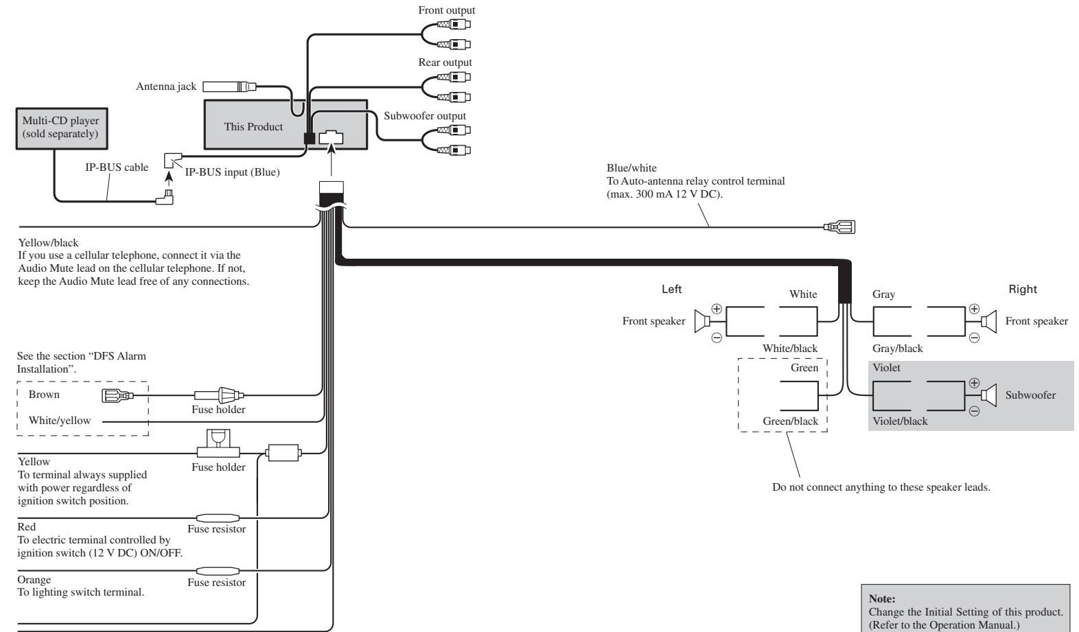
■ When using a Subwoofer without using a different amp (sold separately)
flowchart
graph TD
A["Multi-CD player (sold separately)"] --> B["IP-BUS cable"]
B --> C["IP-BUS input (Blue)"]
C --> D["This Product"]
D --> E["Front output"]
D --> F["Rear output"]
D --> G["Subwoofer output"]
H["Yellow/black<br>If you use a cellular telephone, connect it via the Audio Mute lead on the cellular telephone. If not,<br>keep the Audio Mute lead free of any connections."] --> I["Blue/white<br>To Auto-antenna relay control terminal<br>(max. 300 mA 12 V DC)."]
J["See the section "DFS Alarm Installation""] --> K["Fuse holder"]
K --> L["Fuse holder"]
L --> M["Fuse resistor"]
M --> N["Orange<br>To lighting switch terminal."]
O["Red<br>To electric terminal controlled by ignition switch (12 V DC) ON/OFF."] --> P["Fuse resistor"]
Q["Left"] --> R["Front speaker"]
S["Right"] --> T["Front speaker"]
U["Do not connect anything to these speaker leads."] --> V["Green/black"]
W["White/black"] --> X["Gray/black"]
Y["Violet/black"] --> Z["Violet"]
AA["White/yellow"] --> AB["Fuse holder"]
AC["Blue/white"] --> AD["Blue/white To Auto-antenna relay control terminal"]
AE["Red"] --> AF["Fuse resistor"]
Black (ground) To vehicle (metal) body.
CAUTION
- Because of the complexity of today's technically advanced vehicle wiring systems, we recommend that your DFS Alarm be installed ONLY by a professional Pioneer installer.
Affix the included deterrent stickers to the inside of the front door windows.
Description
■ White/yellow (DOOR SWITCH) ...... (Fig. 4 & 5)
This lead is used to trigger DFS Alarm when any door is opened and may be connected to either positive or negative (+/-) type door pin switches.
■ Brown (ALARM OUTPUT) ...... (Fig. 6)
This lead is a pulsed positive (+) output capable of driving up to 2 relays (500 mA) max. Use this lead to trigger relays for siren, horn, honk or flashing lights.
Door Switches
The DFS Alarm's door trigger input is designed to work with either positive or negative door pin switches. After hookup, simply set door system type from DFS Alarm Setting Menu.
Domelight Delay-DFS Alarm will wait for last door to close and courtesy light to turn off before Exit Delay Timer Starts.
Note: Change the Initial Setting of this product. (Refer to the Operation Manual.)
DOOR SWITCH (White/yellow)
Grounding Type Switch:
GM, Chrysler, Japanese and most European vehicles.
Note:
- Set DFS Alarm to recognize ground trigger from DFS Alarm Setting Menu. Set Door System to “Door System: Negative, Current mode: Close”.
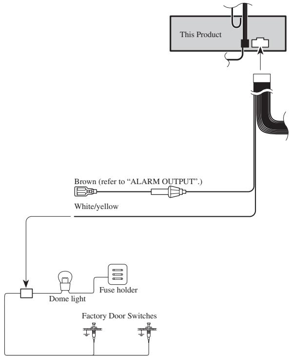
flowchart
graph TD
    A["This Product"] --> B["Line"]
    B --> C["White/yellow"]
    C --> D["Dome light"]
    D --> E["Fuse holder"]
    E --> F["Factory Door Switches"]
    style A fill:#f9f,stroke:#333
    style B fill:#ccf,stroke:#333
    style C fill:#cfc,stroke:#333
    style D fill:#fcc,stroke:#333
    style E fill:#cff,stroke:#333
    style F fill:#ffc,stroke:#333
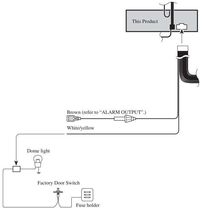
Positive (Non-grounding) Type Switch:
Ford, Jaguar, Mercedes
Note:
- Set DFS Alarm to recognize positive trigger from DFS Alarm Setting Menu. Set Door System to "Door System: Positive, Current mode: Close".
flowchart
graph TD
    A["Factory Door Switch"] --> B["Dome light"]
    B --> C["Fuse holder"]
    C --> D["White/yellow"]
    D --> E["This Product"]
    E --> F["Alarm OUTPUT"]
    F --> G["Brown (refer to "ALARM OUTPUT".)"]
Fig. 5
Installing New Pin Switches
Separately sold pin switches are available that can be used to protect your vehicle's trunk, hood, etc. When you purchase these, make sure that you first confirm that they can be used with your vehicle's door system type.
Follow the makers instructions as to installation and wiring.
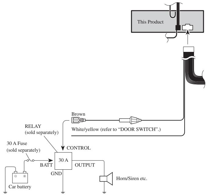
ALARM OUTPUT (Brown)
The brown lead provides a +12 V, pulsed output while alarm is sounding. This lead has a maximum current capability of 500 mA and can be used to trigger a relay to sound a siren, horn or flash lights.
Recommended Wiring:
30 amp relay (sold separately) required to operate siren, horn or lights.
- Connect Brown wire to one side of relay coil.
- Connect ground to other side of coil.
For sirens, horns or lights requiring +12 V trigger
- Connect normally open pin to fused, constant +12 V source.
For horns or lights requiring ground trigger
- Connect normally open pin to ground.
flowchart
graph TD
    A["Car battery"] --> B["30 A Fuse (sold separately)"]
    B --> C["BATT"]
    C --> D["30 A"]
    D --> E["OUTPUT"]
    E --> F["Horn/Siren etc."]
    G["Brown"] --> H["White/yellow (refer to "DOOR SWITCH".)"]
    I["This Product"] --> J["Line"]
    K["RELAY (sold separately)"] --> L["CONTROL"]
    M["30 A Fuse (sold separately)"] --> L
Fig. 6
Installation
Note:
- Before finally installing the unit, connect the wiring temporarily, making sure it is all connected up properly, and the unit and the system work properly.
- Use only the parts included with the unit to ensure proper installation. The use of unauthorized parts can cause malfunctions.
- Consult with your nearest dealer if installation requires the drilling of holes or other modifications of the vehicle.
- Install the unit where it does not get in the driver's way and cannot injure the passenger if there is a sudden stop, like an emergency stop.
- The semiconductor laser will be damaged if it overheats, so don't install the unit anywhere hot — for instance, near a heater outlet.
- If installation angle exceeds 60^ from horizontal, the unit might not give its optimum performance. (Fig. 7)
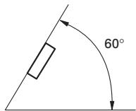
Fig. 7
DIN Front/Rear-mount
This unit can be properly installed either from “Front” (conventional DIN Front-mount) or “Rear” (DIN Rear-mount installation, utilizing threaded screw holes at the sides of unit chassis). For details, refer to the following illustrated installation methods.
DIN Front-mount
Installation with the rubber bush (Fig. 8)
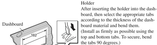
text_image
Dashboard 182 Holder After inserting the holder into the dashboard, then select the appropriate tabs according to the thickness of the dashboard material and bend them. (Install as firmly as possible using the top and bottom tabs. To secure, bend the tabs 90 degrees.)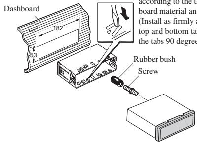
text_image
Dashboard 182 53 according to the t board material and (Install as firmly a top and bottom ta the tabs 90 deg Rubber bush ScrewFig. 8
Installation without the rubber bush (Fig. 9)
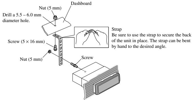
text_image
Nut (5 mm) Dashboard Drill a 5.5 - 6.0 mm diameter hole. Screw (5 × 16 mm) Nut (5 mm) Screw Strap Be sure to use the strap to secure the back of the unit in place. The strap can be bent by hand to the desired angle.Fig. 9
Removing the Unit (Fig. 10) (Fig. 11)
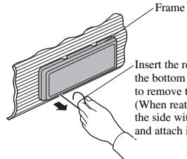
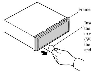
text_image
Frame Insert the re- t bottom to remove t- (When reat- the side with and attach iInsert the release pin into the hole in the bottom of the frame and pull out to remove the frame.
(When reattaching the frame, point the side with a groove downwards and attach it.)
Fig. 10
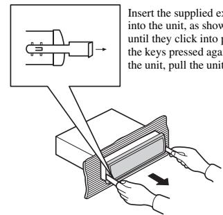
text_image
Insert the supplied ex into the unit, as show until they click into p the keys pressed again the unit, pull the unitFig. 11
DIN Rear-mount
Installation using the screw holes on the side of the unit
- Remove the frame. (Fig. 12)
text_image
Frame Insert the to re (WI the andInsert the release pin into the hole in √ the bottom of the frame and pull out to remove the frame.
(When reattaching the frame, point the side with a groove downwards and attach it.)
Fig. 12
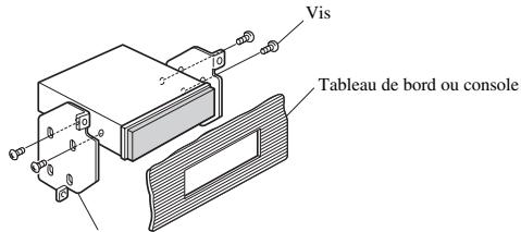
- Fastening the unit to the factory radio mounting bracket. (Fig. 13) (Fig. 14)
Select a position where the screw holes of the bracket and the screw holes of the head unit become aligned (are fitted), and tighten the screws at 2 places on each side. Use either binding screws (5 × 6 mm) or flush surface screws (5 × 6 mm), depending on the shape of the screw holes in the bracket.
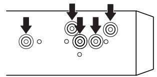
natural_image
Pure diagram of circular components with downward arrows indicating flow or movement (no text or symbols)Fig. 13
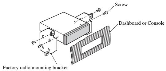
text_image
Screw Dashboard or Console Factory radio mounting bracketFig. 14
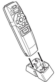
Installing the Remote Control Unit
Fitting the Remote Control Unit
Precaution:
- Press the remote control unit onto the mounting base until it clicks into place.
Fitting horizontally (Fig. 15)
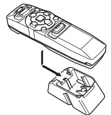
natural_image
Line drawing of a remote control device with an open lid and internal components (no text or symbols)Fig. 15
Fitting vertically (Fig. 16)
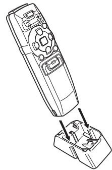
natural_image
Line drawing of a remote control device with an open base and internal components (no text or symbols)Fig. 16
Installation Using the Mounting Base
Precaution:
- To avoid it being a hindrance to driving, always install the remote control unit to the passenger's side – not the driver's side.
• Install the mounting base so that the remote control unit is slanting upwards at an angle when fitted. - Before using double-sided tape, clean off any dirt on the surface to which the double-sided tape is to be attached.
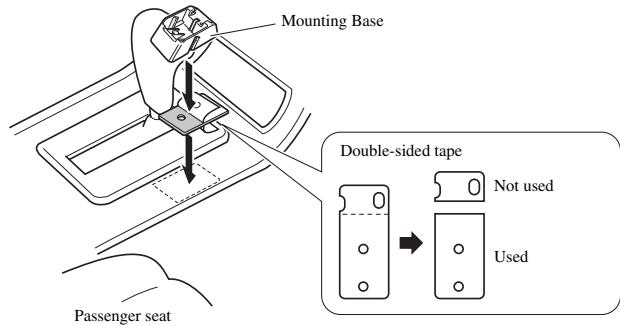
text_image
Mounting Base Double-sided tape Not used Used Passenger seatRemarque:
natural_image
Pure diagram of mechanical components with arrows indicating downward motion, no text or symbols presentFig. 13
natural_image
Line drawing of a remote control box with internal components, showing an open lid and internal wiring (no text or symbols)Fig. 15
Montage vertical (Fig. 16)
natural_image
Line drawing of a remote control device with an open base and internal components (no text or symbols)Fig. 16