
WS4904P - Motion detector DSC - Free user manual and instructions
Find the device manual for free WS4904P DSC in PDF.


| Brand | DSC |
| Model | WS4904P |
| Product Type | Wireless Motion Detector |
| Operating Frequency | 433.92 MHz (WS4904) |
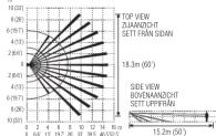
| Detection Range (Wall-to-Wall Lens, Fast Mode) | 15.2 x 18.3 m |
| Detection Range (Wall-to-Wall Lens, Slow Mode) | 10.6 x 18.3 m |
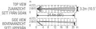
| Detection Range (Corridor Lens) | 24.4 x 3.2 m |
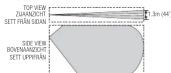
| Detection Range (Curtain Lens) | 15.2 x 1.3 m |
| Detection Range (Pet Alley Lens, Fast Mode) | 15.2 x 18.3 m |
| Detection Range (Pet Alley Lens, Slow Mode) | 15.2 x 10.5 m |
| Mounting Height (Standard Lenses) | 6-10 ft (2-3 m) from floor |
| Mounting Height (Pet Alley Lens) | 4-5 ft (1.2-1.5 m) from floor |
| Power Source | One 3V Lithium battery (CR123A type) |
| Recommended Batteries | Energizer EL123AP, Panasonic CR123A, Duracell Ultra 123 |
| Battery Life | 9 years (typical usage) |
| Low Battery Threshold | 2.2 V |
| Operating Temperature | -10°C to 55°C (14°F to 131°F) |
| Operating Humidity | 5% to 93% RH non-condensing |
| Compliance | EN50131-2-2 Grade 2 Class II, Type C |
| Compatible Receivers | RE5132-433/868, RF4164-433/868, RFK55X0-433/868, RF5108-433/868, SCW9045/47-433/868, SCW9055/57-433, PC9155-433/868 |
| Lens Options | Wall-to-Wall (standard), Corridor, Curtain, Pet Alley |
| Sensitivity Settings | Fast and Slow (selectable via jumper JP1) |
| Special Modes | High Traffic Shutdown (3-minute delay), Walk Test Mode, 6-second transmission delay |
| Tamper Protection | Screw required; backplate tamper detection |
| Usage Location | Indoor only, non-hazardous |
Frequently Asked Questions - WS4904P DSC
User questions about WS4904P DSC
0 question about this device. Answer the ones you know or ask your own.
Ask a new question about this device
Download the instructions for your Motion detector in PDF format for free! Find your manual WS4904P - DSC and take your electronic device back in hand. On this page are published all the documents necessary for the use of your device. WS4904P by DSC.
USER MANUAL WS4904P DSC
WS4904/WS8904 - Installation Instructions
This Installation Manual shall be used in conjunction with the Installation Manual of the DSC wireless receiver and control panel with which this device is intended to be used. Each WS4904/WS8904 motion detector should be located so that it provides optimal coverage of the intended area. Refer to Changing Motion Detector Lenses below for information on the four lenses available for the WS4904/WS8904 Motion Detector.
Installing the Detector
When locating motion detectors, observe the following, for Wall-to-Wall, Corridor and Curtain Lenses, the mounting height should be 6-10 ft/2-3m from the floor. The nominal mounting height is 7.5 ft./2.3m. For the Pet Alley Lens only, the mounting height should be 4-5 ft./1.2-1.5m from the floor.
Consider the following to avoid false alarms:
- Do not aim the detector at a stairwell to which a pet has access - Do not access furniture at objects higher than 3ft (2.0m) which
- Do not place furniture or objects higher than 5ft (0.9m) which a pet can climb onto (e.g. a cat on a couch), closer than 6ft (1.8m) from the detector
- Mount the detector flat on a wall or in a
when it is used in conjunction with pets • Do not aim the detector at reflective surfaces such as mirrors or windows as this may distort the coverage pattern or
Do not aim the detector at retective surfaces such as mirrors of windowed as this the reflect sunlight directly onto the detector.
- Avoid locations that are subject to direct high air flow such as near an air duct outlet
- Do not locate the detector near sources of moisture such as steam or oil
- Do not limit the coverage by large obstructions in the detection area such as plants or cabinets
• For indoor use only (non-hazardous locations)
NOTE: No detector should be mounted without first performing a module placement test to determine that it is
in range of the wireless receiver. See the Plan or in the Installation Manual for your system
When a location has been selected, remove the plastic from the mounting holes and locate the backplate on the wall and
mark screw locations. It is suggested that wall anchors be used for all screw locations. Secure the backplate to the wall, and then secure the enrolled detector to its backplate.
NOTE: Use only backplates marked as "Type-1". Using any other backplates will result in the timer switch
NOTE: 600-6 being broken
Enrolling a WS4904/WS8904
On the back of the PIB housing, there will be a six-dinit number.
On the back of the first housing, will win to be a six-digit man. Changing Motion Detector Lenses
Changing Motion Detector Lenses Each motion detector is supplied with the Wall-to-Wall lens: three additional lenses are available for the WS4904/WS8904
motion detector. The charts on the following page illustrate the range and coverage patterns of each lens.
To change the lens, first open the motion detector by removing the screw in the bottom of the battery compartment. With
the screw removed, pull the back of the detector away from the front case. Remove the lens holder by pressing down on the top of the holders and pulling the holder away from the rear. When installing the previous frame, remove the removal of the lens from
up of the holder and pulling the holder away from the case. When insailing the new lens, ensure the grooved surface laces the interior of the eye, and the patches on the laser face the bottom of the case. Disperse the line holders by opening it
the interior of the case, and the hotches on the lens face the bottom of the case. Replace the lens holder by snapping it back into place. Reassemble the motion detector by first arranging the clips on the bottom of the case. Close the clip and
back into place. To assemble the motion doctor by first engaging the clips on it, then secure the case with the screw in the bottom of the battery compartment.
Changing the Motion Detector Sensitivity
The motion detector features Fast and Slow detection modes, which are set on jumper JP1. In a normal operating environ-
ment, the fast setting provides the best detection.
In certain environments where rapid air movement, heaters and other variables present problems, use Slow detection mode
to stabilize the detection. Jumper "JP1" is located at the top right under the battery bucket of the circuit board. To change the setting from East to Slow move the jumper over one pin, as shown in Figure 4.
the sliding from fast to slow, move the jumper of High Traffic Shortlamps.
High Traffic Shutdown Mode
To prolong battery life, the motion detector uses a feature called High Traffic Shutdown. When motion is detected, the device will undergo? As the receiver and will then shift down for three minutes. Motion is detected again during the next day.
device will transmit to the receiver and will then shut down for three minutes. If motion is detected again during the shutdown time, the unit will not transmit the event to the receiver. The detector will thus remain in the shutdown mode until
down time, the drill will not transmit the event to the receiver. The detector will thus remain in the shutdown mode until three minutes after the first motion detected was transmitted. The detector will transmit detected motion every three minu-
les.
The High Traffic Shutdown Mode affects testing the motion detector in two ways:
- When performing the module placement test, the unit must be tampered by removing it from the backplate and repla-
cing it. The placement test cannot be performed by creating motion in front of the device.
- When performing a system test, the unit must be left idle for three minutes before testing can be performed. Once
three minutes has passed, create motion in front of the detector to see if the device is both detecting motion and
transmitting to the receiver.
Motion Detector Transmission Delay
A motion detector transmission is always delayed by six seconds. This is necessary to prevent false alarms caused by a
motion sensor transmitting before a delay zone has a chance to report. This six-second delay cannot be altered or disabled.
Walk Test Mode
The motion detector has a walk test mode which will activate an LED for testing purposes. During normal operation, the
LED will not turn on. To put the detector in walk test mode, create a tamper by removing the detector from its backplate and
then replacing it. Each time the detector senses motion, it will flash the red LED. Six seconds after motion is detected, the detector will send a signal to the receiver. The detector will be in walk text mode until it has sent 10 transmissors. To test
detector will send a signal to the receiver. The detector will be in walk test mode until it has sent to transmissions to test for catch performance of humans, create motion in the entire area where coverage is desired by walking perpendicular to
the lens pattern. Should the coverage be incomplete, rearlurst or relocate the detector
NOTE: The Walk Test Mode will override the High Traffic Shutdown Mode.
NOTE: If the installer is activating the walk test mode or replacing a battery then he must create 10 alarm trans-
missions before leaving the area, because the indicator is still working and will not stop working until 10 alarm
transmissions have been sent.
Battery Installation (Fig.3)
• This system is designed to work with the following consumer grade batteries: Energizer Lithium EL123AP, Panasonic
Lithium CR123A or Duracell Lithium Ultra 123. Do not install any other type. The reliability of the security system
depends on its batteries, and "no name" or generic brand batteries may not provide the best quality and dependability. Use of another type of battery you magnet a risk of fire as misleading.
my. Use of another type of battery may present a risk of life or explosion. Use a fresh battery. Most batteries have a "best before" data printed on f
- Use a resin battery, most batteries have a "best before" date printed on then packaging or on the batteries themselves. Buy batteries that have a "best before" date of two years or more from your purchase date.
Remove the motion detector from its mounting plate by holding the sensor by its sides and pushing up. Remove the battery
cover (see Figure 3). Remove the old battery and install new battery. Place the battery cover back on
NOTE: Secure the battery cover with the small screw provided.
Replace the sensor on its mounting plate, making sure it snaps into place. After the battery is installed, the detector will take
60 seconds to warm up. During this time the LED will flash slowly.
NOTE: The polarity of the battery must be observed (Figure3). Improper handling of lithium batteries may
result in heat generation, explosion or fire, which may lead to personal injuries.
WARNING: DANGER OF EXPLOSION IF BATTERIES ARE INSTALLED INCORRECTLY. REPLACE ONLY WITH THE SAM
OR EQUIVALENT TYPE RECOMMENDED BY THE MANUFACTURER.
Keep away from small children. In batteries are swallowed, promptly see a doctor. Do not try to recharge these batteries. Disposal of used batteries must be made in accordance with the waste recovery and rescaling uses
batteries. Disposal of used batteries must be made in accordance with the waste recovery and recycling regulations in your own
Istions in your area.
WARNING: The battery may explode if mistreated. Do not dispose of in fire, recharge or disassemble
Instrument: The utility may expose if introduced. Do not expose or in info, recharge or unassociate.
Specifications
- Operating Temperature: -10°C to 55°C (14°F to 131°F) - Operating Humidity: 5 to 93% RH non-cond
• Operating Frequency: 433.92MHz (WS4904)
- Operating frequency: 450 x SEMFE (WD 100 V), 600 x SEMFE (WD 800 V) - Battery Life: 9 years (typical usage in room temperature)
- Battery Nominal Voltage is 3V. Low Battery Trouble indication is provided at 2.2V
• Compatible with: RE5132-433/868, RF4164-433/868, RFK55X0-433/868, RF5108-433/868, SCW9045/47-433/
868, SCW9055/57-433, PC9155-433/868, WS4920/WS8920

29007298R002
WS4904/WS8904 - Installatiehandleiding
OPMERKING: Gean ankle melder dient to worden nongrates
High Traffic Shutdown Modus
WS4904/WS8904 - installationshandbok
This manual shall be used in conjunction with the Control Panel Installation Manual
This equipment shall be installed by Service Persons only (service person is defined as a person having the appropriate technical training and experience necessary to be aware of hazards to which that person may be exposed in performing a task and of measures to minimize the risks to that person or other persons). It shall be installed and used within an environment that provides the pollution degree max 2, over voltages category II, in non-hazardous, indoor locations only.
The reference to the WS4904/WS8904 throughout this manual is applicable to the following model
numbers: WS4904 NA, WS4904 EU and WS8904.
This product meets the requirements of Class II, Grade 2 equipment as per EN50131-1, EN50131-2-2 and EN50131-6 Standard. The new products in Type C group EN50131-6 Standard
and EN30131-6 Standardus. The power supply is Type C as per EN30131-6 Standardu.
The slow mode is not to be used for EN50131-2-2 compliant installations.
Tested and certified by Telefication according to EN 50131-2-2 (2008) grade 2 class II. The Model W6004 Wireless BIP motion detector has been certified by Telefication
The Model W38904 Wireless FIR motion detector has been certified by Telefication according to EN50131-2-2, EN50131-6 for Grade 2, Class II, Type C. According to EN 50131-1:2006 and AI:2009
EN 50131-2-2, EN 50131-6 job Grade 2, Class II, Type C. According to EN 50131-7.2000 and AT.200) this equipment can be applied in installed systems up to and including Security Grade 2.
the Equivalent can be applied in insulated systems up to and reducing security grade 21.
Hereby. DSC. declares that this device is in compliance with the
requirements and other relevant provisions of Directive 1999/5/EC.
The complete B&TTE Declaration of Conformity can be found
http://www.dsc.com/listings_index.aspx
IMPORTANT - READ CAREFULLY: DSC Software purchased with or without Products and Components is copyrighted and is purchased under the following license terms:
Components is copyrighted and is purchased under the following license terms: • This End-User License Agreement ("EULA") is a legal agreement between You (the company, individual or acquired the Software and any related Hardware) and Digital Security Controls, a division of Tyco Safety Products
Canada Ltd. ("DSC"), the manufacturer of the integrated security systems and the developer of the software and any related products or components ("HARDWARE") which You acquired.
- If the DSC software product ("SOFTWARE PRODUCT" or "SOFTWARE") is intended to be accompanied by HARDWARE, and is NOT accompanied by new HARDWARE, you may not use, copy or install the SOFTWARE PRODUCT. The SOFTWARE PRODUCT includes computer software, and may include associated media, printed materials, and "online" or electronic documentation.
- Any software provided along with the SOFTWARE PRODUCT that is associated with a separate end-user license agreement is licensed to You under the terms of that license agreement.
- by installing, copying, downloading, storing, accessing or otherwise using the SOFTWARE PRODUCT, you agree unconditionally to be bound by the terms of this EULA, even if this EULA is deemed to be a modification of any previous arrangement or contract. If You do not agree to the terms of this EULA, DSC is unwilling to license the SOFTWARE PRODUCT to You, and You have no right to use it.
SOFTWARE PRODUCT LICENSE The SOFTWARE PRODUCT is granted
THE SOFTWARE PRODUCT is protocol by copyright laws and international copyright thanks, as well as other molecular property laws and treaties. THE SOFTWARE PRODUCT is licensed, not sold. 1. GRANT OF LICENSE. This FILL & grants You the following rights:
(a) Software Installation and Use - For each license You acquire
PRODUCT installed. (b) Storage/Network Use - The SOFTWARE PRODUCT may not be installed, accessed, displayed, run, shared or used
concurrently on or from different computers, including a workstation, terminal or other digital electronic device ("Device"). In other words, if You have several workstations, You will have to acquire a license for each workstation where the SOFTWARE will be used.
(c) Backup Copy = You may make back-up copies of the SOFTWARE PRODUCT, but You may only have one copy per license installed at you given time. You may use the back-up copy solely for award purposes. Except as explicitly
Intrise transferred in any given units. You may use the S&P-UP copy solely for other purposes. Except to expressly provided in this EULA, You may not otherwise make copies of the SOFTWARE PRODUCT, including the printed materials, accompanying the SOFTWARE
- DESCRIPTION OF OTHER RIGHTS AND LIMITATIONS
(a) Limitations on Reverse Engineering, Decompilation and Disassembly. You may not reverse engineer, decompile, or disassemble the SOFTWARE PRODUCT, except and only to the extent that such activity is expressly permitted by
applicable law notwithstanding this limitation. You may not make any changes or modifications to the Software, without the written permission of an officer of DSC. You may not remove any proprietary notices, marks or labels from the Software
Product. You shall institute reasonable measures to ensure compliance with the terms and conditions of this EULA. (b) Separation of Components - The SOFTWARE PRODUCT is licensed as a single product. Its component parts may not
(c) Single INTEGRATED PRODUCT- If You acquired this SOFTWARE with HARDWARE, then the SOFTWARE PRODUCT is
licensed with the HARDWARE as a single integrated product. In this case, the SOFTWARE PRODUCT may with the HARDWARE as set forth in this ELLA
(d) Rental - You may not rent, lease or lend the SOFTWARE PRODUCT. You may not make it available to others or post it on a server or web site.
(e) Software Product Tran
transfer of the HARDWARE, provided You retain no copies, You transfer all of the SOFTWARE PRODUCT (including all component parts, the media and printed materials, any upgrades and this EULA), and provided the recipient agrees to the
terms of this EULA. If the SOFTWARE PRODUCT is an upgrade, any transfer must also include all p SOFTWARE PRODUCT.
(7) Termination - Without prejudice to any other rights, DSC may terminate this EULA if You fail to comply with the terms and conditions of this EULA. In such event, You must destroy all copies of the SOFTWARE PRODUCT and all of its components
parts. (3) Trademarks - This EULA does not grant You any rights in connection with any trademarks or service marks of DSC or its
suppliers. 2. COPYRIGHT - All title and intellectual property rights in and to the SOFTWARE PRODUCT (including but not limited to any
- Our Trust - An text and institutional property rights in this the SOFTWARE PRODUCT (including but not limited to any images, photographs, and text incorporated into the SOFTWARE PRODUCT), the accompanying printed materials, and any cover of the SOFTWARE PRODUCT are owned by DSC or its suppliers. You may not copy the printed materials
Copies of the Software Product, are owned by 50% or its suppliers. You may not copy the printed material accompanying the SOFTWARE PRODUCT. All title and intellectual property rights in and to the content which may be accepted from such use of the SOFTWARE PRODUCT are the properties of the respective content paper and may be properly
assessed through use of the SOF N/ALE Property are the property of the respective content owner and may be protected by applicable copyright or other intellectual property laws and treaties. This EULA grants You no rights to use such content. All rights not properly granted under this EULA are reserved by DSC and its suppliers.
-
EXPORT RESTRICTIONS - You agree that You will not export or re-export the SOFTWARE PRODUCT to any country
-
CHOICE OF LAW - This Software License Agreement is governed by the laws of the Province of Ontario, Canada.
d. ARBITRATION - An disputes arising in connection with the Agreement shall be determined by initial and ending arbitration in accordance with the Arbitration Act, and the parties agree to be bound by the arbitrator's decision. The place of arbitration shall be Toronto, Canada, and the owners of the arbitration shall be London.
- LIMITED WARRANTY
(a) NO WARRANTY - DSC PROVIDES THE SOFTWARE "AS IS" WITHOUT WARRANTY. DSC DOES NOT WARRANT THAT THE SOFTWARE WILL MEET YOUR REQUIREMENTS OR THAT OPERATION OF THE SOFTWARE WILL BE
THE SOFTWARE WILL MEET YOUR REGULMENTS OF THIS OBLIGATION OF THE SOFTWARE WILL BE UNINTERRUPTED OR ERROR-FREE.
(d) CHANGES IN OPERATING ENVIRONMENT - DSC shall not be responsible for problems caused by changes in the operating characteristics of the HARDWARE, or for problems in the interaction of the SOFTWARE PRODUCT with non-
(c) LIMITATION OF LIABILITY; WARRANTY REFLECTS ALLOCATION OF RISK - IN ANY EVENT, IF ANY STATUTE
IMPLIES WARRANTIES OR CONDITIONS NOT STATED IN THIS LICENSE AGREEMENT, DSC'S ENTIRE LIABILITY UNDER ANY PROVISION OF THIS LICENSE AGREEMENT SHALL BE LIMITED TO THE GREATER OF THE AMOUNT ACTUALLY PAID
BY YOU TO LICENSE THE SOFTWARE PRODUCT AND FIVE CANADIAN DOLLARS (CAD\$5.00). BECAUSE SOME EXTRACTIONS DO NOT ALLOW THE EXCLUSION OR LIMITATION OF LIABILITY FOR CONSENSUAL OR INCIDENTAL
JURISOCIATIONS DO NOT ALLOW THE EXCLUSION OR LIMITATION OF LIABILITY FOR CONSEQUENTIAL OR INCIDENTAL DAMAGES, THE ABOVE LIMITATION MAY NOT APPLY TO YOU.
(d) DISCLAIMER OF WARRANTIES - THIS WARRANTY CONTAINS THE ENTIRE WARRANTY AND SHALL BE IN LIEU OF ANY AND ALL OTHER WARRANTIES, WHETHER EXPRESSED OR IMPLIED INCLUDING ALL IMPLIED WARRANTIES OF
MERCHANTABILITY OR FITNESS FOR A PARTICULAR PURPOSE) AND OF ALL OTHER OBLIGATIONS OR LIABILITIES ON THE PART OF PROFIT.
THE PART OF DSC, DSC MAKES NO OTHER WARRANTIES. DSC NEITHER ASSUMES NOR AUTHORIZES ANY OTHER PERSON PURPORTING TO ACT ON ITS BEHALF TO MODIFY OR TO CHANGE THIS WARRANTY, NOR TO ASSUME FOR IT ANY OTHER WARRANTIES OR LIABILITY CONCEDING THE SOFTWARE PRODUCT.
(e) EXCLUSIVE REMEDY AND LIMITATION OF WARRANTY - UNDER NO CIRCUMSTANCES SHALL DSC BE LIABLE
FOR ANY SPECIAL, INCIDENTAL, CONSEQUENTIAL OR INDIRECT DAMAGES BASED UPON BREACH OF WARRANTY, BREACH OF CONTRACT, NEGLIGENCE, STRICT LIABILITY, OR ANY OTHER LEGAL THEORY, SUCH DAMAGES INCLUDE
UNDERST OF CONTRACT, INDEPENDENCE, OTTOST LIABILITY, OR ANY OTHER SLONE IN THIS OFF-BEANSABLE ORDER, BUT ARE NOT LIMITED TO LOSS OF PROFITS. LOSS OF THE SOFTWARE PRODUCT OR ANY ASSOCIATED EQUIPMENT.
COST OF CAPITAL, COST OF SUBSTITUTE OR REPLACEMENT EQUIPMENT, FACILITIES OR SERVICES, DOWN TIME, PURCHASERS TIME, THE CLAIMS OF THIRD PARTIES, INCLUDING CUSTOMERS AND INJURY TO PROPERTY.
WARNING: DSC recommends that the entire system be completely tested on a regular basis. However, despite frequent testing and due to, but not limited to criminal tampering or electrical disruption. It is
Despite frequent lossing, and also to, but not limited to, criminal to possible for this SOFTWARE PRODUCT to fail to perform as expected.
NOTE: For Installations compliant with EUS0131.2.2 Standard, the range for the "East" Setting is 15.2 x 10.3 m. The "Slow" set
NOTE: For installation, ting shall not be used.
Wall-to-Wall Lens (Standard)
50' × 60" (15.2 × 18.3m)
"Slow" Setting / "I angzame" instelling / "I ångsamt"
lâne -
35' × 60" (10.6 × 18.3m)
BV-L2-UV
Corridor lens (optional)
Comductor (optional)
Ganglens (optionee
Komdorslins (valtn)
80' × 10.5' (24.4 × 3.2m)
BV-L3-UV
Curtain lens (optional)
Curtains (optional)
Gordjmlens (optione
Gardinlins (valtri)
50' × 4.4' (15.2 × 1.3m)
DV 1.4 HV
BV-L4-UV
Pet Alley lens (optional)
Pet Alley lens (huisdierenlens) (optioneel)
50' × 60' (15.2 × 18.3m
30 × 60 (15.2 × 10.0m)

For installations compliant with EN50131-2-2 Class 2
requirements the mounting screws shall be placed as
Indicated in the diagram in order to provide tamper protection against removal from the wall of the device
protection against removal from the wall of the device
Figure 2.1: The following table provides the original text in the image.

Mounting hole knockouts
Ensure proper orientation of Backplate
Corner mounting knockouts
After testing, insert the provided screw to prevent tampering
NOTE: Must have screw to prevent tampering.
Changing the Sensitivity Setting
NOTE: The SLOW mode is not to be used on
EN50131-2-2 compliant installations
ORMERKING: (In installatie die veldaren gen ENF0121
The trademarks, logos, and service marks displayed on this document are registered in the United States [or other countries]. Any misuse of the trademarks is strictly prohibited and Tyco International Ltd. will aggressively enforce its intellectual property rights to the fullest extent of the law, including pursuit of criminal prosecution wherever necessary. All trademarks not owned by Tyco International Ltd. are the property of their respective owners, and are used with permission or allowed under applicable laws.
Product offerings and specifications are subject to change without notice. Actual products may vary from photos. Not all products include all features. Availability varies by region; contact your sales representative.
© 2014 Tyco International Ltd. and its Respective Companies. All Rights Reserved.


- WS4904/WS8904 - Installation Instructions
- Installing the Detector
- Enrolling a WS4904/WS8904
- On the back of the PIB housing, there will be a six-dinit number.
- Changing the Motion Detector Sensitivity
- Motion Detector Transmission Delay
- WS4904/WS8904 - Installatiehandleiding
- WS4904/WS8904 - installationshandbok
Brand : DSC
Model : WS4904P
Category : Motion detector