
HX-40AM - Motion detector OPTEX - Free user manual and instructions
Find the device manual for free HX-40AM OPTEX in PDF.


| Product Type | Motion Detector (Passive Infrared with Anti-Masking) |
| Brand | Optex |
| Model | HX-40AM |
| Detection Method | Passive Infrared (PIR) |
| Coverage Range | 12.0 m (40 ft) at 85° wide |
| Detection Zones | 94 zones |
| Detectable Speed | 0.3 m/s to 1.5 m/s |
| Sensitivity | 2.0 °C at 0.6 m/s |
| Power Input | 9.5 to 18 V DC |
| Current Draw | 40 mA max (at 12 V DC) |
| Alarm Output | Form C, 28 V DC, 0.2 A max |
| Tamper Output | N.C., 28 V DC, 0.1 A max |
| Trouble Output | N.C., 28 V DC, 0.1 A max (anti-masking) |
| LED Indicator | Red: warm-up, alarm, trouble |
| Operating Temperature | -20 to +60 °C |
| Weatherproof Rating | IP55 |
| Mounting Height | 2.5 to 3.0 m (8.2 to 9.8 ft) |
| Dimensions (with bracket & hood) | 266 × 99 × 205 mm (10.47 × 3.90 × 8.07 in) |
| Weight | 700 g (24.7 oz) |
| Accessories Included | Bracket, hood, area masking seals, screws |
| Anti-Masking | Digital anti-masking (infrared LED) |
| Special Features | Vegetation sway analysis, dual signal processing, intelligent AND logic |
| Bracket Adjust Angle | Vertical ±20°, Horizontal ±95° |
| Mounting Options | Wall mount with or without bracket |
Frequently Asked Questions - HX-40AM OPTEX
User questions about HX-40AM OPTEX
0 question about this device. Answer the ones you know or ask your own.
Ask a new question about this device
Download the instructions for your Motion detector in PDF format for free! Find your manual HX-40AM - OPTEX and take your electronic device back in hand. On this page are published all the documents necessary for the use of your device. HX-40AM by OPTEX.
USER MANUAL HX-40AM OPTEX
natural_image
Technical line drawing of a mechanical component with no visible text or symbolsHigh Mount Outdoor Detector HX-40/40AM/ 40DAM

N219
| HX-40 2 PIRs standard model |
| HX-40AM HX-40 with anti-masking |
| HX-40DAM HX-40AM with micro-wave |
• 3.0 m high mount detection area (12.0 m)
- Unique pyro element
- Intelligent AND logic
• Dual signal processing logic
• Vegetation sway analysis logic
- Ideal detection area setting
• Digital anti-masking (AM/DAM model only)
- Microwave range selector (DAM model only)
CONTENTS
1 INSTALLATION PRECAUTIONS .....2
1-1 BEFORE INSTALLATION 2
1-2 PARTS IDENTIFICATION ....3
1-3 KNOCKOUTS 4
1-4 DETECTION AREA....5
1-5 DETERMINATION OF PIR
DETECTION LENGTH ....5
2 INSTALLATION 6
2-1 MOUNTING WITH BRACKET ......6
2-2 ADJUSTING THE VERTICAL ANGLE....8
2-3 MOUNTING WITHOUT
BRACKET....9
2-4 WIRING 10
2-5 WALL TAMPER (OPTION) .....11
3 WALK TEST 12
4 SETTING 13
5 AREA ADJUSTMENT 16
6 LED INDICATION 17
7 SPECIFICATIONS ....18
7-1 SPECIFICATIONS ....18
7-2 DIMENSIONS 19
1 INSTALLATION PRECAUTIONS
1-1 BEFORE INSTALLATION
 | Failure to follow the instructions provided with this indication and improper handling may cause death or serious injury. |
 | Failure to follow the instructions provided with this indication and improper handling may cause injury and/or property damage. |
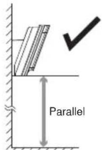
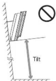
The check √ mark indicates recommendation.
The nix sign indicates prohibition.
| Warning Warning | Caution |
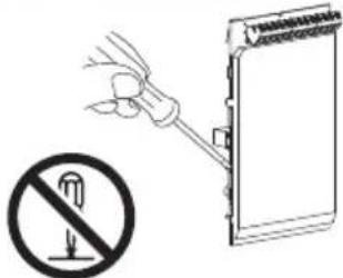 Do not repair or modify product Do not repair or modify product | 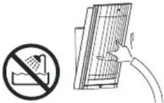 Keep product away from waterMount the unit securely Keep product away from waterMount the unit securely |
| Mounting height | Keep the detector parallel to the ground. | |
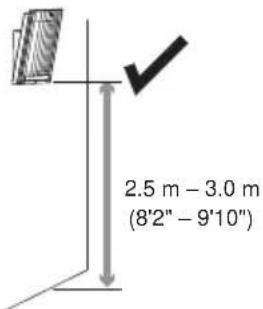 |  |  |
natural_image
Illustration of a person walking with directional arrows indicating light or motion (no text or symbols)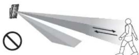
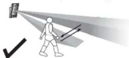
Consider the direction a person is approaching from, as well as the detection area.
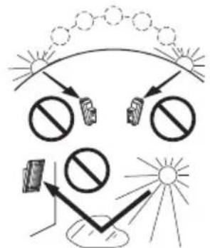
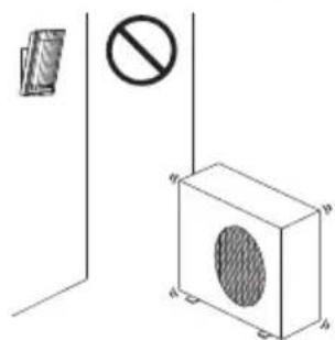
natural_image
Diagram showing a device with a prohibition symbol and a cabinet-like structure with a perforated lid (no text or labels)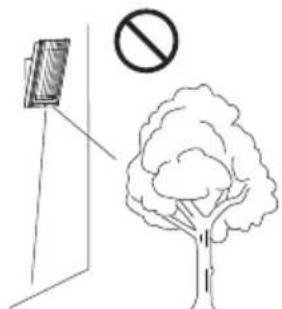
Do not install two or more HX-40DAM's units side-by-side or face-to-face. Instead, install them back-to-back. If mounting on the same wall, be sure they are at least 1.0 m (3'3") apart from each other.
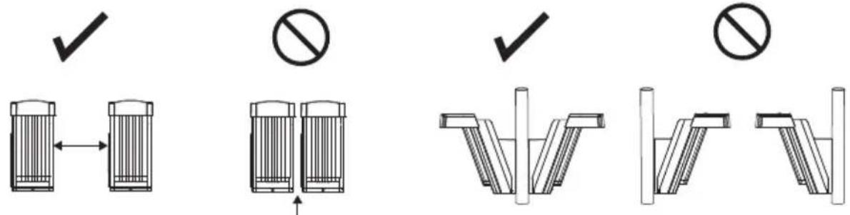
1.0 m (3'3") or more Less than 1.0 m (3'3")
1-2 PARTS IDENTIFICATION
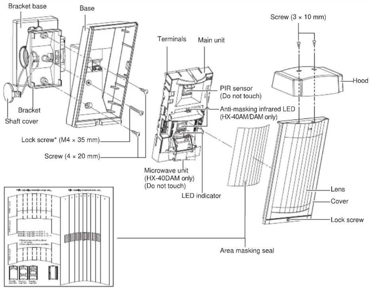
Screw kit
| For joint For wall mounting For hood | ||
| Screw (4 × 20 mm) | Screw (4 × 20 mm) Screw (3 × 10 mm) | |
*Lock screw attached on bracket base
1-3 KNOCKOUTS
Main unit
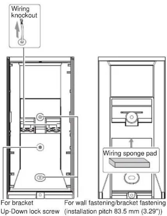
Bracket
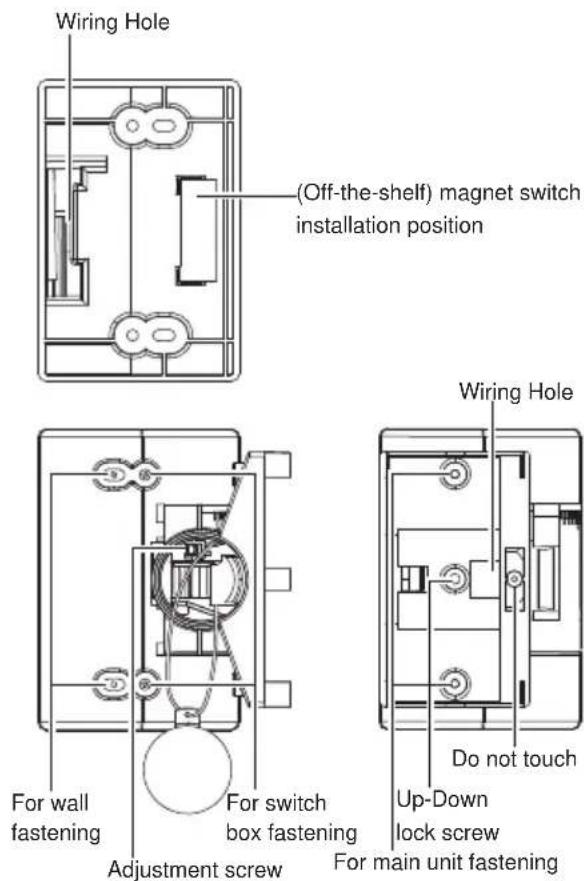
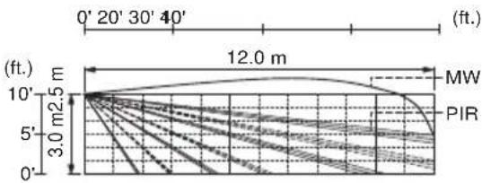
1-4 DETECTION AREA
(Mounting height: 3.0 m (9'10"))
line
| Wind Speed (ft.) | MW | PIR | | ---------------- | ------ | ------ | | 0 | 0 | 0 | | 20 | 5 | 5 | | 30 | 10 | 10 | | 40 | 12.0 | 12.0 | | 50 | 10 | 10 | | 60 | 5 | 5 | | 70 | 0 | 0 |(Mounting height: 2.5 m (8'2"))
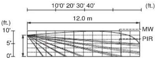
line
| Longitude | Latitude | | --------- | -------- | | 0° | 10° | | 5° | 5° | | 10° | 0° | | 15° | 5° | | 20° | 10° | | 25° | 12.0 | | 30° | 10° | | 35° | 5° | | 40° | 0° | | 45° | 5° | | 50° | 10° | | 55° | 12.0 | | 60° | 10° | | 65° | 5° | | 70° | 0° | | 75° | 5° | | 80° | 10° | | 85° | 12.0 | | 90° | 10° | | 95° | 5° | | 100° | 0° | | 105° | 5° | | 110° | 10° | | 115° | 12.0 | | 120° | 10° | | 125° | 5° | | 130° | 0° | | 135° | 5° | | 140° | 10° | | 145° | 12.0 | | 150° | 10° | | 155° | 5° | | 160° | 0° | | 165° | 5° | | 170° | 10° | | 175° | 12.0 | | 180° | 10° | | 185° | 5° | | 190° | 0° | | 195° | 5° | | 200° | 10° | | 205° | 12.0 | | 210° | 10° | | 215° | 5° | | 220° | 0° | | 225° | 5° | | 230° | 10° | | 235° | 12.0 | | 240° | 10° | | 245° | 5° | | 250° | 0° | | 255° | 5° | | 260° | 10° | | 265° | 12.0 | | 270° | 10° | | 275° | 5° | | 280° | 0° | | 285° | 5° | | 290° | 10° | | 295° | 12.0 | | 300° | 10° | | 305° | 5° | | 310° | 0° | | 315° | 5° | | 320° | 10° | | 325° | 12.0 | | 330° | 10° | | 335° | 5° | | 340° | 0° | | 345° | 5° | | 350° | 10° | | 355° | 12.0 | | 360° | 10° | | 365° | 5% | | 370° | 0% | | 375° | 5% | | 380° | 10% | | 385° | 12% | | 390° | 10% | | 395° | 5% | | 400° | 0% | | 405° | 5% | | 410° | 10% | | 415° | 12% | | 420° | 10% | | 425° | 5% | | 430° | 0% | | Note: The last row is a duplicate of the first row to close the circle in the image. The rest of the image is empty. The data is presented in a table format as shown above and below the table headers.- Vertical angle: 1 click (2.5°) upward (Refer to "caution" in 2-2).
Top viewSide view
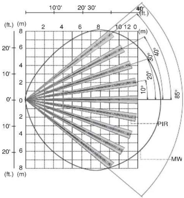
radar
| Angle (°) | Radius (ft.) | |-----------|--------------| | 0 | 0 | | 10 | 1 | | 20 | 2 | | 30 | 3 | | 40 | 4 | | 50 | 5 | | 60 | 6 | | 70 | 7 | | 80 | 8 | | 90 | 9 | | 100 | 10 | | 110 | 11 | | 120 | 12 | | 130 | 13 | | 140 | 14 | | 150 | 15 | | 160 | 16 | | 170 | 17 | | 180 | 18 | | 190 | 19 | | 200 | 20 | | 210 | 21 | | 220 | 22 | | 230 | 23 | | 240 | 24 | | 250 | 25 | | 260 | 26 | | 270 | 27 | | 280 | 28 | | 290 | 29 | | 300 | 30 | | 310 | 31 | | 320 | 32 | | 330 | 33 | | 340 | 34 | | 350 | 35 | | 360 | 36 | | 370 | 37 | | 380 | 38 | | 390 | 39 | | 400 | 40 | | 410 | 41 | | 420 | 42 | | 430 | 43 | | 440 | 44 | | 450 | 45 | | 460 | 46 | | 470 | 47 | | 480 | 48 | | 490 | 49 | | 500 | 50 | | 510 | 51 | | 520 | 52 | | 530 | 53 | | 540 | 54 | | 550 | 55 | | 560 | 56 | | 570 | 57 | | 580 | 58 | | 590 | 59 | | 600 | 60 | | 610 | 61 | | 620 | 62 | | 630 | 63 | | 640 | 64 | | 650 | 65 | | 660 | 66 | | 670 | 67 | | 680 | 68 | | 690 | 69 | | 700 | 70 | | 710 | 71 | | 720 | 72 | | 730 | 73 | | 740 | 74 | | 750 | 75 | | 760 | 76 | | 770 | 77 | | 780 | 78 | | 790 | 79 | | 800 | 80 | | Note: The 'Size' column is estimated based on the 'Radius' axis label (e.g., 'm') and 'Direction' label (e.g., 'PIR'). The 'MW' label is not explicitly shown in the provided code. The 'M' label is not used in the chart.1-5 DETERMINATION OF PIR DETECTION LENGTH
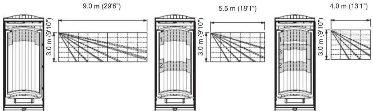
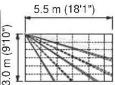
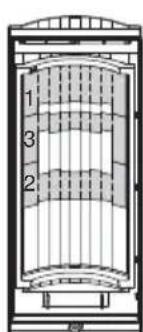
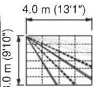
To adjust the detection length, apply the masking seals to the back of the lens according to the required detection length. Three types of masking seals are provided. Combine them according to the detection length required.
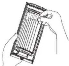
natural_image
Line drawing of hands holding a rectangular device with internal grid lines (no text or symbols)Apply masking seal directly on the back side of the lens.
For microwave detection setting please refer to "4 SETTING".
2 INSTALLATION
Use the bracket for normal installation. The unit may be mounted directly on the wall, without the bracket, only if the following three conditions are not;
• The mounting height 3.0 m (9'10").
• Horizontal direction adjustment is unnecessary.
• The ground is level.
2-1 MOUNTING WITH BRACKET
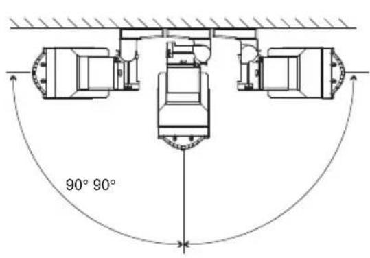
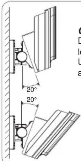
Using the bracket makes it possible to adjust the unit horizontally by ± 90^ . In cases where the ground is uneven and/or not parallel with the base of the unit, it is possible to adjust the unit vertically by ± 20^ .
Caution>>
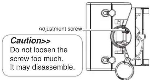
Do not change the detection length with bracket.
Use the masking seal to adjust the detection length.
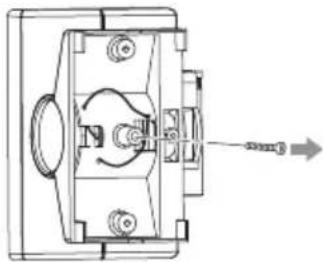
1 Remove the Up-Down lock screw.
natural_image
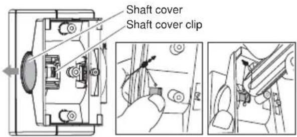
Technical line drawing of a mechanical assembly with no visible text or symbols2 Push the shaft cover clip straightforwardly with your thumb. In case the clip is stuck, use a suitable tool. e.g. back side of a screw driver.
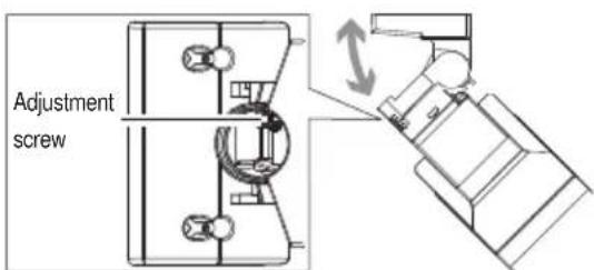
3 Loosen the adjustment screw two turns.
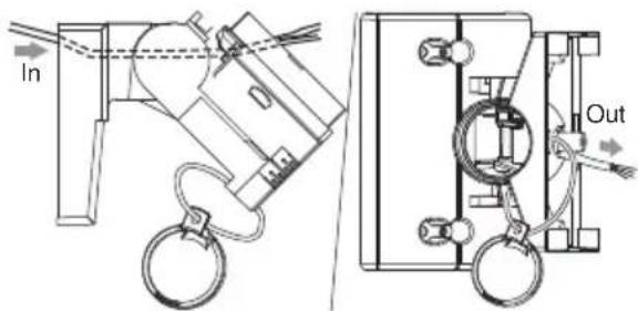
4 Tilt the bracket about 45^ and pass through the wire.
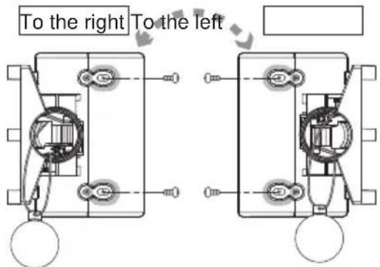
5 Determine the horizontal direction (left or right) of the detector before installing the bracket on the wall.
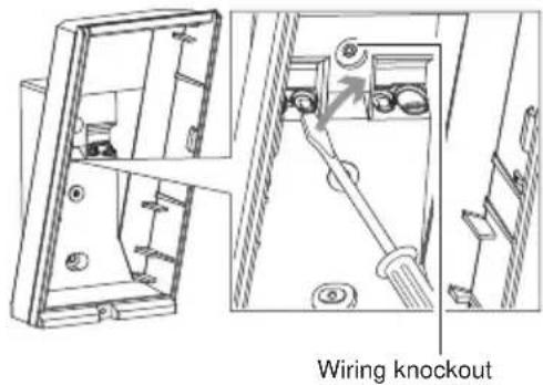
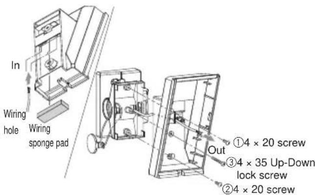
6 Open the wiring knockout.
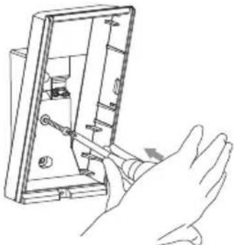
7 Open the Up-Down lock screw knockout for connecting the bracket.
natural_image
Line drawing of a hand inserting a component into a device housing (no text or symbols)Knockout with 4 × 20 tapping screw (screwkit)
8 Tighten screws ① and ②, adjust the bracket angle (refer to 2-2), then tighten screw ③. Perform an area check. If re-adjustment is required, loosen screw ③ and change the bracket angle. After the adjustment is complete, tighten screw ③ again.
9 Tighten the adjustment screw clockwise.
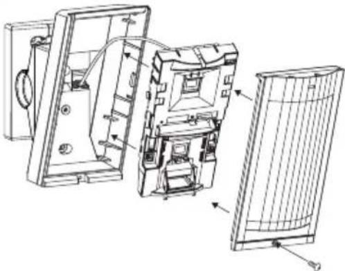
10 Wire to the terminal and install the main unit and lens on the base.
natural_image
Technical line drawing of an open electronic device showing internal components and external casing (no text or symbols)11 Install the shaft cover into place.
2-2 ADJUSTING THE VERTICAL ANGLE
For best performance, install detector parallel to the ground.
Decide the detection length. If you choose 9.0 m/5.5 m/4.0 m, mask the unnecessary lens with masking seals. Refer to the 1-5 for the details.
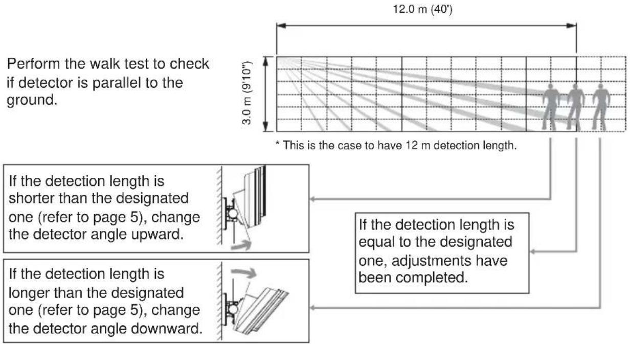
Caution>>
If the base of the unit is already parallel to the ground,
- Do not change the detection length by tilting the unit up or down. Detection length should be adjusted with masking seal. Refer to 1-5 and 2-1 for the details.
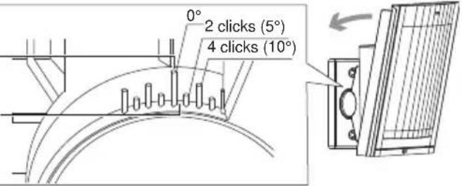
Example (the ground is level)
0° is the right setting for 3.0 m (9'10") height installation.
Adjust 1 click (2.5° upward) for 2.5 m (8'2") height installation.
2-3 MOUNTING WITHOUT BRACKET
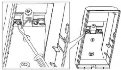
1 Open the wiring knockout with suitable tool e.g. screwdriver.
natural_image
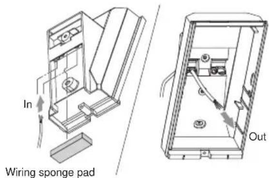
Technical line drawing showing a mechanical assembly with a lever and housing, no text or symbols present2 Pull the wire through the base knockout.
3 Fasten the base to the wall.
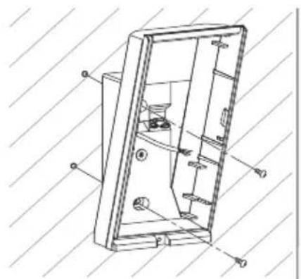
natural_image
Technical line drawing of a mechanical device with internal components and mounting holes (no text or symbols)4 Install main unit after wiring to the terminal.
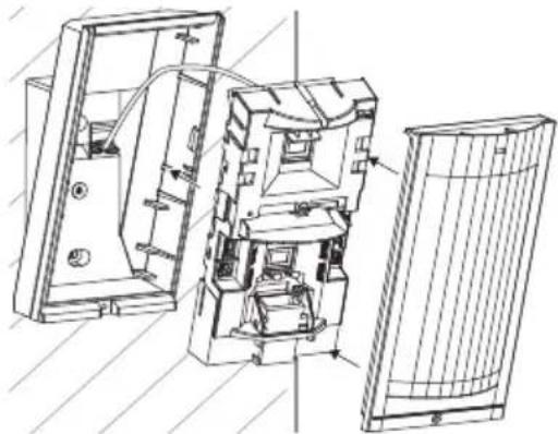
natural_image
Technical line drawing of an electronic device showing internal components and housing (no text or symbols)2-4 WIRING
Power wires should not exceed the following lengths.
| WIRE GAUGE | HX-40 HX-40AM HX-40DAM | |||||
| 12 V 14 | V 12 V 14 V | 12 V 14 V | ||||
| AWG22 (0.33 mm2) | 160 m(520') | 360 m(1,180') | 140 m(460') | 310 m(1,020') | 120 m(390') | 250 m(820') |
| AWG20 (0.52 mm2) | 260 m(850') | 560 m(1,840') | 230 m(750') | 490 m(1,610') | 180 m(590') | 390 m(1,280') |
| AWG18 (0.83 mm2) | 410 m(1,350') | 900 m(2,950') | 360 m(1,180') | 780 m(2,560') | 290 m(950') | 630 m(2,070') |
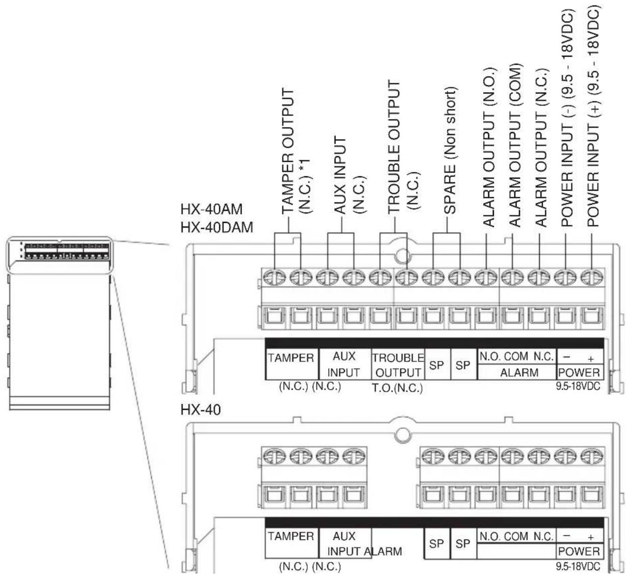
*1: TAMPER terminals to be connected to a 24 hour supervisory loop.
2-5 WALL TAMPER (OPTION)
Universal magnet switch may be mounted as a wall tamper.
Installation space for universal magnet switch is provided on the back of the main unit and the bracket.
Maximum size of an applicable universal magnet switch: D 9 mm (0.35") × W 40 mm (1.57") × H 9 mm (0.35").
Universal magnet switch on the market assist is not included.
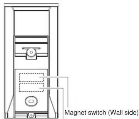
Magnet switch (Base side) installation position
BracketMain unit
Wiring Hole
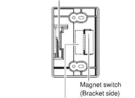
Magnet switch (Wall side) installation position
Magnet switch (Bracket side) installation position
-Installation
1 Install the universal magnet switch (wall side) to the wall. To determine the install position, use the "Install position template" provided on the inside cover of the product package.
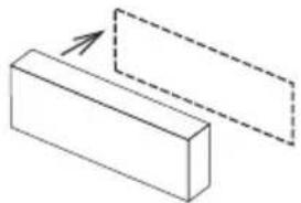
natural_image
Simple line drawing of a rectangular block with an arrow pointing to its top edge, no text or symbols present.2 Open the wiring knockout with suitable tool e.g. screwdriver.
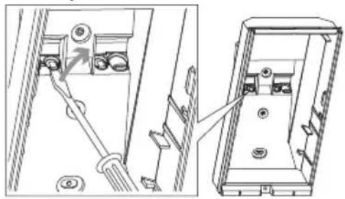
natural_image
Technical line drawing showing a mechanical assembly with a lever and housing (no text or symbols)3 Install the other portion of the universal magnet switch to the back of the main unit or the bracket. Pull the wiring through the knockouts.
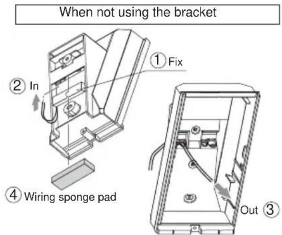
When using the bracket
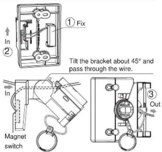
4 Install the bracket and the main unit to the wall surface.
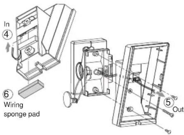
5 Connect the universal magnet switch wiring to the tamper terminal of the main unit.
3 WALK TEST
1 Set the DIP switch 1 (LED ON/OFF) to "ON".
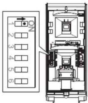
Note>>
The switch is set "ON" by factory default.
2 Check that the detector detects an object in the intended detection area. The installation has been successful if the LED lights for two seconds after a person walks into the detection area.
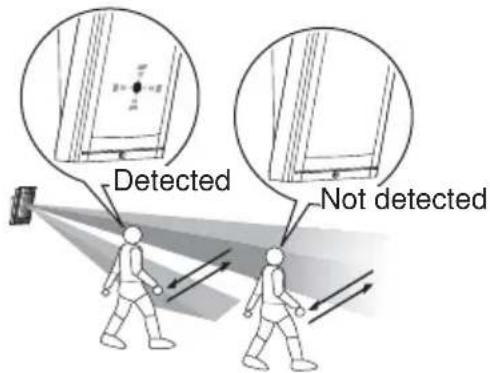
Note>>
For the walk test, move more than 1.0 m (3'3") away from the detector.
3 If the LED indication is not required at all times, set the DIP switch 1 (LED ON/OFF) to "OFF".
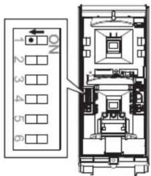
4 SETTING
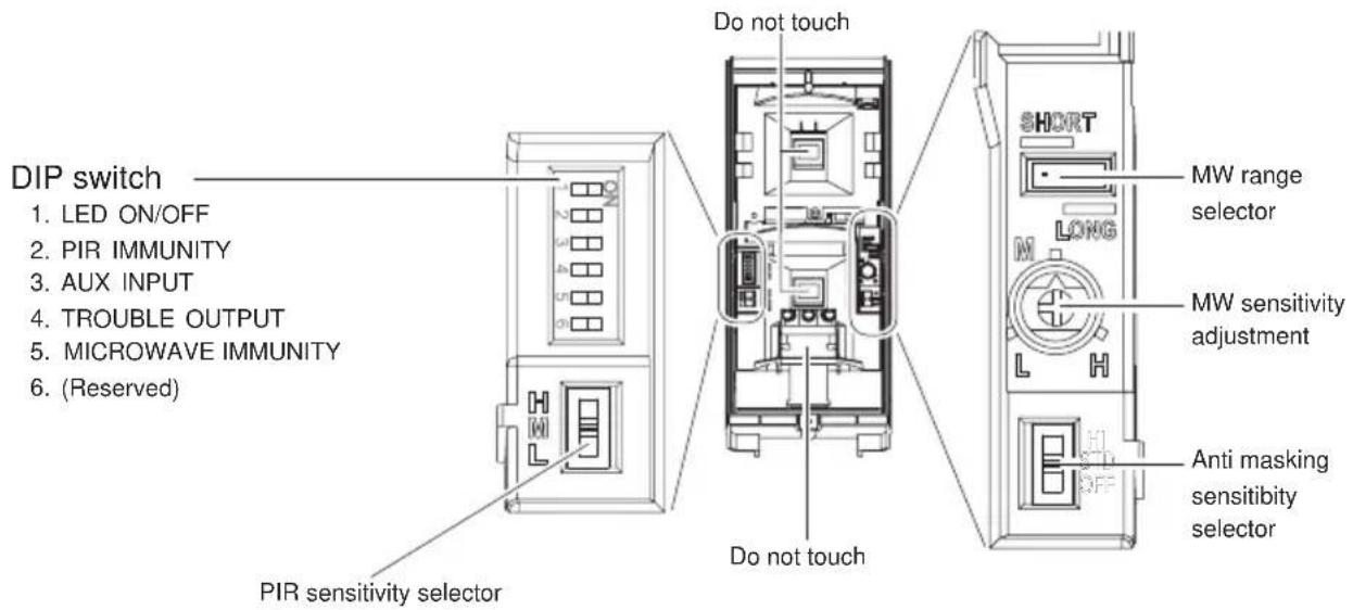
-LED ON/OFF DIP switch
1
HX-40
HX-40AM
HX-40DAM
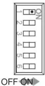
| POSITION FUNCTION | |
| ON(Factory default) | The LED lights when someone is detected. |
| OFF | The LED does not light even if someone is detected. |
-PIR IMMUNITY DIP switch
2
HX-40
HX-40AM
HX-40DAM
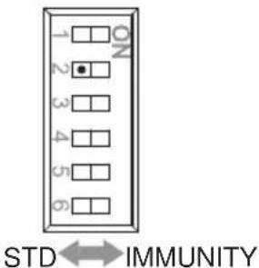
| POSITION FUNCTION | |
| STD (Factory default) | PIR IMMUNITY logic is not activated. |
| IMMUNITY | PIR IMMUNITY logic is activated. Use this under harsh environment (e.g. small animal). |
By connecting a satellite unit (another warning sensor), you can extend the detection area and correct false alarms. As a satellite unit, you can use any general no-voltage contact output (NC) warning sensor, including the following.
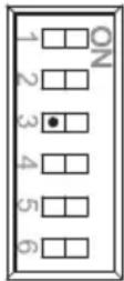 | POSITION FUNCTION | |
| AND(Factory default) | When both the main unit and the satellite detect someone, the alarm is output.Set to this when not connecting a satellite unit. | |
| OR | When either the main unit or the satellite detects someone, the alarm is output. | |
AND OR
Notes>>
- The alarm does not output unless both the main unit and the satellite detect someone within 60 sec.
- If the OR mode is selected without a satellite unit connected, the alarm is generated continuously.
-TROUBLE OUTPUT DIP switch
4
HX-40
HX-40AM
HX-40DAM
Trouble output is used for anti-masking signal.
When an object is placed close to the lens surface, for a period of more than 180 sec., the IR Anti-Masking circuit is activated and generates a trouble signal.
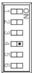

| POSITION FUNCTION | |
| ON(Factory default) | Anti-masking signal is output from TROUBLE OUTPUT terminal. |
| OFF | Anti-masking signal is output from both TROUBLE and ALARM OUTPUT terminal. |
ONOFF
Note>>
Use this when not wiring a detected trouble input terminal on the control panel.
-MICROWAVE IMMUNITY
DIP switch
5
HX-40
HX-40AM
HX-40DAM
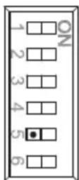
STD IMMUNITY
| POSITION FUNCTION | |
| STD (Factory default) | MICRO WAVE IMMUNITY logic is not activated. |
| IMMUNITY | MICRO WAVE IMMUNITY logic is activated. Use this under harsh environment (e.g. vegetation sway). |
-MW RANGE SELECTOR/MW SENSITIVITY ADJUSTMENT
RANGE SELECTOR/SENSITIVITY ADJUSTMENT
HX-40 HX-40AM HX-40DAM
| PIR AREA SETTING | DETECTION AREA(SIDE VIEW) | MW RANGESELECTOR | MW SENSITIVITYADJUSTMENT | |
| 12.0 m(40') | 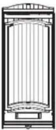 | 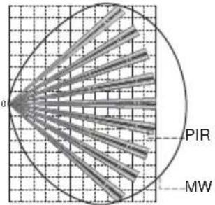 | LONGSHORT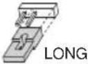 | MID--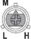 |
| Factory default | ||||
| 9.0 m(29'6") | 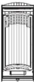 | 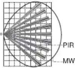 | SHORTSHORT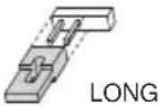 | HIGHM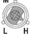 |
| 5.5 m(18'1") | 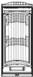 | 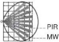 | SHORTSHORT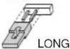 | MID** |
| 4.0 m(13'1") | 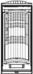 | 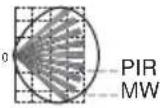 | SHORTSHORT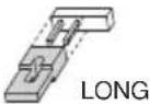 | LOW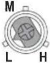 |
-PIR SENSITIVITY
PIR
SENSITIVITY SELECTOR
HX-40
HX-40AM
HX-40DAM
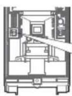
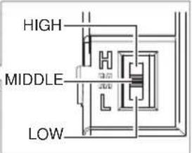
| POSITION FUNCTION | |
| HIGH High sensitivity | |
| MIDDLE (Factory default) | Middle sensitivity |
| LOW Low sensitivity | |
-ANTI-MASKING SENSITIVITY
ANTI-MASKING
SENSITIVITY SELECTOR
HX40
HX-40AM
HX-40DAM
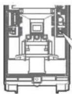
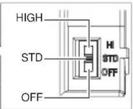
| POSITION FUNCTION | |
| HIGH High sensitivity | |
| STD(Factory default) | Standard sensitivity |
| OFF Disabled | |
Caution>>
When closing the cover, do not leave any object within 1 meter from the unit.
5 AREA ADJUSTMENT
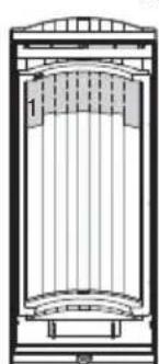
-DETECTION LENGTH ADJUSTMENT
To limit the detection length, apply the appropriate masking seal. Note that there are three different types of seal.
natural_image
Architectural cross-section diagram of a building facade with vertical supports and curved structural elements (no text or symbols)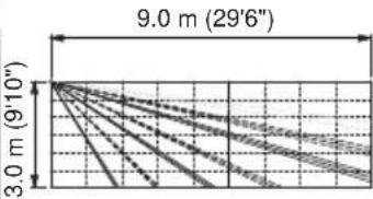
line
| X | Y | |---|---| | 3.0 m (9'10") | 9.0 m (29'6") | | 9.0 m (29'6") | 3.0 m (9'10") |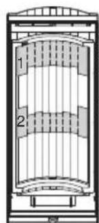
-AREA MASKING
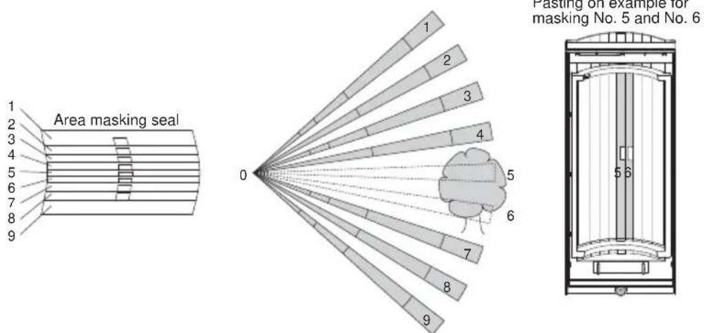
Pasting on example for masking No. 5 and No. 6
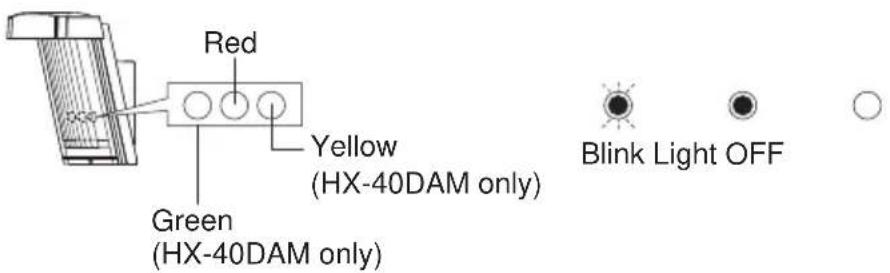
-HX-40/40AM
| DETECTOR CONDITION LED INDICATOR (RED ONLY) | ||
| Warm-up |  Blinks for approx. 60 sec. Blinks for approx. 60 sec. | |
| Alarm |  Lights for 2 sec. Lights for 2 sec. | |
| Trouble output | Anti-Masking booting(Anti-Masking start up) | 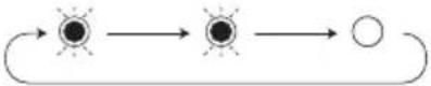 Blinks 2 times and goes off for 5 sec. and then repeats for 180 sec. Blinks 2 times and goes off for 5 sec. and then repeats for 180 sec. |
| Masking detection |  Blinks 3 times and goes off for 3 sec. and then repeats. Blinks 3 times and goes off for 3 sec. and then repeats. | |
-HX-40DAM
| DETECTOR CONDITION LED INDICATOR | ||
| Warm-up |  Blinks for approx. 60 sec. Blinks for approx. 60 sec. | |
| Alarm |  Red lights for 2 sec. Red lights for 2 sec. | |
| PIR detection |  Green lights for 2 sec. Green lights for 2 sec. | |
| MW detection |  Yellow lights for 2 sec. Yellow lights for 2 sec. | |
| Trouble output | Anti-Masking booting(Anti-Masking start up) |  Green and Red blink 2 times simultaneously and go off for 5 sec. This sequence is repeated for 180 sec. Green and Red blink 2 times simultaneously and go off for 5 sec. This sequence is repeated for 180 sec. |
| Masking detection |  Green and Red blink 3 times simultaneously and go off for 3 sec. This sequence is repeated. Green and Red blink 3 times simultaneously and go off for 3 sec. This sequence is repeated. | |
7 SPECIFICATIONS
7-1 SPECIFICATIONS
| Model HX-40 HX-40AM HX-40DAM | |||
| Detection method Passive infrared Passive infrared & Microwave | |||
| PIR Coverage 12.0 m (40') 85° wide / 94 zones | |||
| PIR distance limit 4.0 m, 5.5 m, 9.0 m (13'1", 18'1", 29'6") | |||
| Detectable speed 0.3 m/s - 1.5 m/s (1'/s - 4'11"/s) | |||
| Sensitivity 2.0°C (3.6°F) at 0.6 m/s | |||
| Power input 9.5 - 18 V DC | |||
| Current draw | 35 mA (max.)at 12 V DC | 40 mA (max.)at 12 V DC | 50 mA (max.)at 12 V DC |
| Alarm period 2.0 ±1 sec. | |||
| Warm-up period Approx. 60 sec. (LED blinks) | |||
| Alarm output Form C 28 V DC 0.2 A (max.) | |||
| Tamper output N.C. 28 V DC, 0.1 A (max.) N.C. open when cover removed. | |||
| Trouble output | - | N.C. 28 V DC, 0.1 A (max.) | |
| Aux input | N.C. 28 V DC, 0.1 A (max.) | ||
| LED indicator | Red: Warm-up,Alarm | Red: Warm-up,Alarm,Trouble | Red:Warm-up, Alarm, TroubleGreen:Warm-up, PIR detect, TroubleYellow:Warm-up, MW detect |
| RF interference | No alarm 10 V/m | ||
| Operating temperature | -20 - +60°C (-4 - +140°F) | ||
| Environment humidity | 95% max. | ||
| Weatherproof | IP55 | ||
| Mounting | Wall | ||
| Mounting height | 2.5 - 3.0 m (8'2" - 9'10") | ||
| Bracket adjust angle | Vertical: ±20° Horizontal: ±95° | ||
| Weight 600 g (21.2 oz.) | 700 g (24.7 oz.) | ||
| Accessories | Bracket, Hood, Area masking seal, Screw (3 × 10 mm) × 2, Screw (4 × 20 mm) × 4 | ||
*Specifications and designs are subject to change without prior notice.
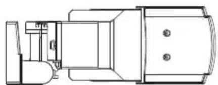
7-2 DIMENSIONS
Using bracket and hood
natural_image
Technical line drawing of a mechanical assembly with no visible text or symbols266 (10.47)
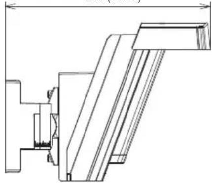
natural_image
Technical line drawing of a mechanical assembly with no visible text or symbols99 (3.90)
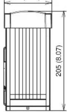
Unit: mm (inch)
Without bracket and hood
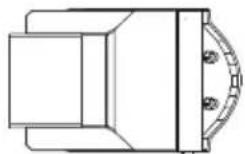
148 (5.83)
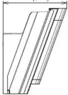
natural_image
Technical line drawing of a mechanical component or bracket (no text or symbols)92 (3.62)
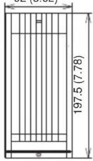
Unit: mm (inch)
The following statement will be provided with the equipment as required by Article 6.3 of the R&TTE Directive, 1999/5/EC.
The Optex HX series are in conformity with all essential requirements of the R&TTE Directive (1999/5/EC). This equipment has been assessed to the following standards:
EN 300 440-1:2009
EN 50130-4: 2004 including amendment 2: 2003
EN 60950-1:2006+A11:2009
This product is marked with which signifies conformity with Class II product requirements specified in the R&TTE Directive.
The following table indicates the areas of intended use of the equipment and any known restrictions. For countries not included in this list, please consult the responsible Spectrum Management Agency.
| Country of intended use | Restrictions | Country of intended use | Restrictions |
| Austria 9.900GHz | Luxembourg 10.525GHz | ||
| Belgium 10.525GHz | The Netherlands 10.525GHz | ||
| Denmark 10.525GHz | Spain 10.525GHz | ||
| Finland 9.900GHz | Sweden 10.525GHz | ||
| France 10.587GHz | United Kingdom 10.587GHz | ||
| Greece 10.525GHz | Other non-EU: Iceland | 10.525GHz | |
| Ireland 10.587GHz | Norway 10.525GHz | ||
| Italy 10.525GHz | Switzerland 10.525GHz |
FCC ID : DC9 OPMW IC : 4012A-OPMW
This device complies with Part 15 of the FCC Rules. Operation is subject to the following two conditions:
(1) This device may not cause harmful interference, and (2) this device must accept any interference received, including interference that may cause undesired operation.
The HX-40 series is only a part of a complete system, therefore we cannot accept complete responsibility for any damages or other consequences resulting from an intrusion.

OPTEX
OPTEX CO., LTD. (JAPAN)
(ISO 9001 Certified)
(ISO 14001 Certified)
5-8-12 Ogoto Otsu
Shiga 520-0101
JAPAN
TEL:+81-77-579-8670
FAX:+81-77-579-8190
URL:http://www.optex.co.jp/e/
OPTEX INCORPORATED (USA)
TEL:+1-909-993-5770
Tech:(800)966-7839
URL:http://www.optexamerica.com/
OPTEX (EUROPE) LTD. (UK)
TEL:+44-1628-631000
URL:http://www.optexeurope.com/
OPTEX SECURITY SAS (FRANCE)
TEL:+33-437-55-50-50
URL:http://www.optex-security.com/
OPTEX SECURITY Sp. z o. o. (POLAND)
TEL:+48-22-598-06-55
URL:http://www.optex.com.pl/
OPTEX KOREA CO., LTD. (KOREA)
TEL:+82-2-719-5971
URL:http://www.optexkorea.com/
OPTEX (DONGGUAN) CO., LTD.
SHENZHEN OFFICÉ (CHINA)
TEL:+86-755-33302950
URL:http://www.optexchina.com/


- High Mount Outdoor Detector HX-40/40AM/ 40DAM
- CONTENTS
- INSTALLATION PRECAUTIONS
- 1-1 BEFORE INSTALLATION
- 1-2 PARTS IDENTIFICATION
- 1-3 KNOCKOUTS
- 1-4 DETECTION AREA
- 1-5 DETERMINATION OF PIR DETECTION LENGTH
- INSTALLATION
- 2-1 MOUNTING WITH BRACKET
- Caution>>
- 2-2 ADJUSTING THE VERTICAL ANGLE
- 2-3 MOUNTING WITHOUT BRACKET
- 2-4 WIRING
- 2-5 WALL TAMPER (OPTION)
- -Installation
- WALK TEST
- Note>>
- SETTING
- -LED ON/OFF DIP switch
- -PIR IMMUNITY DIP switch
- Notes>>
- -TROUBLE OUTPUT DIP switch
- -MICROWAVE IMMUNITY
- -PIR SENSITIVITY
- -ANTI-MASKING SENSITIVITY
- AREA ADJUSTMENT
- -DETECTION LENGTH ADJUSTMENT
- -AREA MASKING
- SPECIFICATIONS
- 7-2 DIMENSIONS
- OPTEX
- OPTEX CO., LTD. (JAPAN)
- OPTEX INCORPORATED (USA)
- OPTEX (EUROPE) LTD. (UK)
- OPTEX SECURITY SAS (FRANCE)
- OPTEX SECURITY Sp. z o. o. (POLAND)
- OPTEX KOREA CO., LTD. (KOREA)
- OPTEX (DONGGUAN) CO., LTD.
- SHENZHEN OFFICÉ (CHINA)
Brand : OPTEX
Model : HX-40AM
Category : Motion detector