
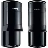
HX-80NAM - Motion detector OPTEX - Free user manual and instructions
Find the device manual for free HX-80NAM OPTEX in PDF.


| Type | Motion Detector (PIR) |
| Brand | Optex |
| Model | HX-80NAM |
| Detection Method | Passive Infrared (PIR) |
| Detection Coverage | 24.0 m x 2.0 m (80' x 6'7") |
| Number of Zones | 20 |
| Detectable Speed | 0.3 m/s – 1.5 m/s (1'/s – 4'11"/s) |
| Sensitivity | 2.0°C (3.6°F) at 0.6 m/s |
| Power Input | 9.5 – 18 V DC |
| Current Draw (max) | 40 mA at 12 V DC |
| Alarm Output | Form C, 28 V DC, 0.2 A max |
| Tamper Output | N.C., 28 V DC, 0.1 A max |
| Trouble Output | N.C., 28 V DC, 0.1 A max |
| Aux Input | N.C., 28 V DC, 0.1 A max |
| Operating Temperature | -20 – +60°C (-4 – +140°F) |
| Environment Humidity | 95% max |
| Weatherproof Rating | IP55 |
| Mounting | Wall |
| Mounting Height | 2.5 – 3.0 m (8'2" – 9'10") |
| Bracket Adjust Angle | Vertical: ±20°, Horizontal: ±95° |
| Weight | 720 g (25.4 oz) |
| Dimensions (with bracket) | 286 x 197.5 x 93 mm (11.26 x 7.78 x 3.66 in) |
| Dimensions (without bracket) | 205 x 197.5 x 93 mm (8.07 x 7.78 x 3.66 in) |
| Special Features | Digital anti-masking, vegetation sway analysis, intelligent AND logic, adjustable detection area with flaps and plates |
| Accessories Included | Bracket, Screw kit (4 x 20 mm x4) |
Frequently Asked Questions - HX-80NAM OPTEX
User questions about HX-80NAM OPTEX
0 question about this device. Answer the ones you know or ask your own.
Ask a new question about this device
Download the instructions for your Motion detector in PDF format for free! Find your manual HX-80NAM - OPTEX and take your electronic device back in hand. On this page are published all the documents necessary for the use of your device. HX-80NAM by OPTEX.
USER MANUAL HX-80NAM OPTEX
natural_image
Technical line drawing of a mechanical assembly with mounting holes and internal components (no text or symbols)High Mount
Outdoor Detector
HK-8ON/8ONAM
HX-80N 2 PIRs standard model
HX-80NAM HX-80N with anti-masking
- Long distance detection area (24.0 m)
- Flexible detection area setting with plates and flaps
- Unique pyro element
- Intelligent AND logic
• Dual signal processing logic
• Vegetation sway analysis logic
• Digital anti-masking (AM model)
CONTENTS
1 INSTALLATION PRECAUTIONS .....2
1-1 BEFORE INSTALLATION ......2
1-2 PARTS IDENTIFICATION ....3
1-3 KNOCKOUTS 3
2 DETECTION AREA....4
2-1 OUTLINE OF DETECTION AREA ...4
2-2 HOW TO REDUCE THE LONG RANGE DETECTION AREA ....6
2-3 HOW TO DEACTIVATE THE SHORT RANGE DETECTION AREA .....8
3 INSTALLATION ....10
3-1 INSTALLING WITH BRACKET .....10
3-2 ADJUSTING THE VERTICAL ANGLE....12
3-3 INSTALLING WITHOUT
BRACKET....12
3-4 WIRING 13
3-5 WALL TAMPER (OPTION) .....14
4 WALK TEST 16
5 SETTING 16
6 LED INDICATION 18
7 SPECIFICATIONS ....19
7-1 SPECIFICATIONS ....19
7-2 DIMENSIONS 20
1 INSTALLATION PRECAUTIONS
1-1 BEFORE INSTALLATION
 | Failure to follow the instructions provided with this indication and improper handling may cause death or serious injury. |
 | Failure to follow the instructions provided with this indication and improper handling may cause injury and/or property damage. |
The check √ mark indicates recommendation.
The nix sign indicates prohibition.
| ⚠ Warning Warning ⚠ | ⚠️ | ⚠️ Caution |
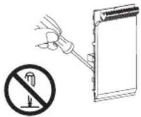 | 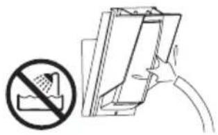 | 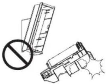 |
| Do not repair or modify product | Keep product away from water | Mount the unit securely |
Mounting height Keep the detector parallel to the ground.
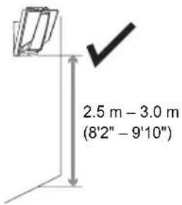
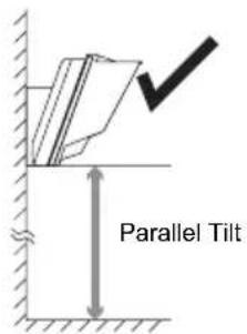
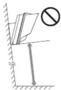
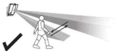
Consider the direction a person is approaching from, as well as the detection area.
natural_image
Illustration of a person walking under a spotlight with directional arrows indicating light or motion (no text or symbols)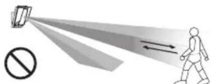
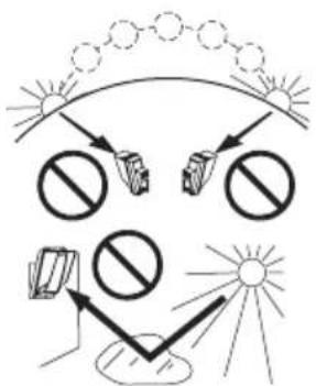
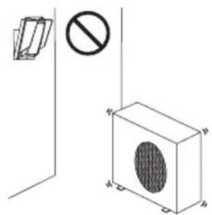
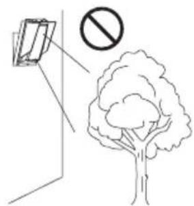
Install the detector in a place where it is free from false alarm factors. For example:
- Sunlight and reflection
- Heat source
- Objects moving in the wind
1-2 PARTS IDENTIFICATION
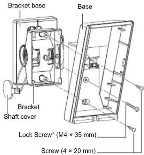
Screw kit
| For joint For wall mounting | |
| Screw (4 × 20 mm) | Screw (4 × 20 mm) |
*Lock screw attached on bracket base
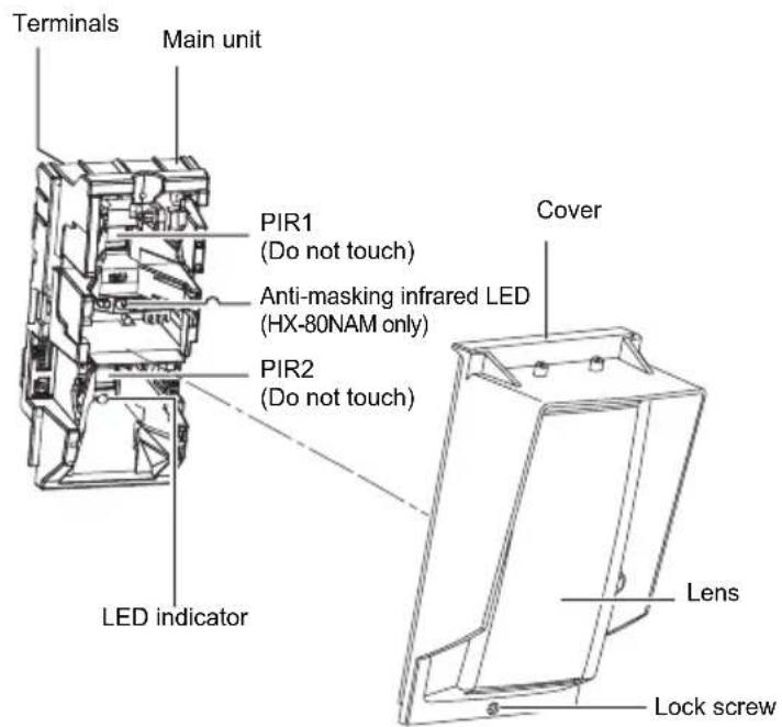
1-3 KNOCKOUTS
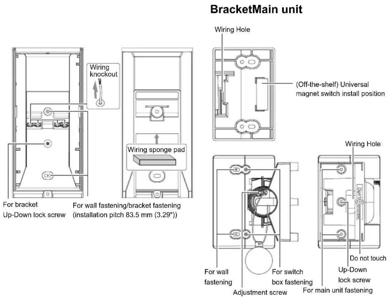
2 DETECTION AREA
2-1 OUTLINE OF DETECTION AREA
DETECTION AREA (factory default)
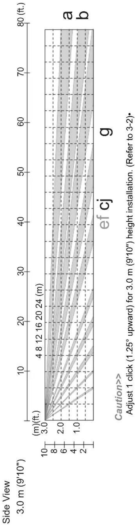
line
| Side View | Height (m) | | --------- | ---------- | | 3.0 m | 3.0 | | 4 | 8.0 | | 8 | 12.0 | | 12 | 16.0 | | 16 | 20.0 | | 20 | 24.0 | | 24 | 28.0 | | ef | 4 | | cj | 8 | | g | 12 |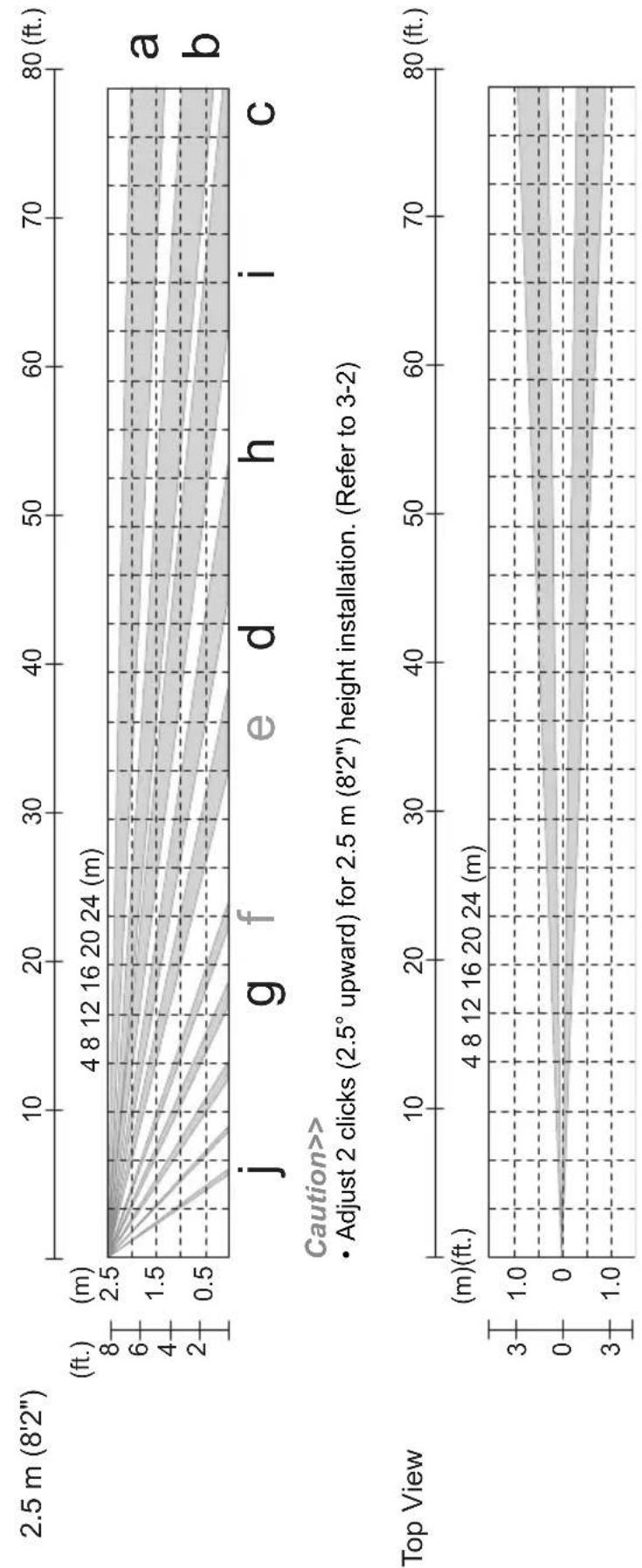
line
| Load (ft.) | Height (m) | | ---------- | ---------- | | 0 | 2.5 | | 10 | 2.0 | | 20 | 1.5 | | 30 | 1.0 | | 40 | 0.5 | | 50 | 0.0 | | 60 | -0.5 | | 70 | -1.0 | | 80 | -1.5 |2-2 HOW TO REDUCE THE LONG RANGE DETECTION AREA
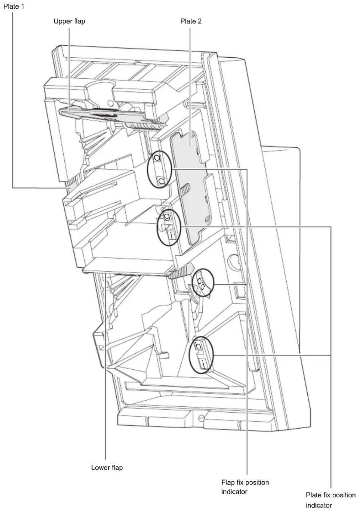
To adjust the LONG range of detection, set the upper and lower flaps as follows:
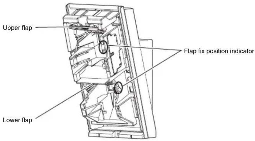
1 Pull out the flap.
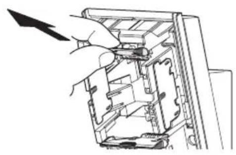
natural_image
Hand inserting a component into a device casing (no text or symbols visible)Note>>
If the lower flap is located at the factory default position, slide it out with your thumb.
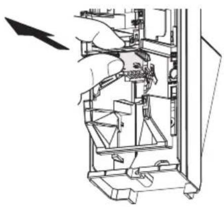
natural_image
Technical line drawing of a mechanical assembly with a hand operating a component (no text or symbols visible)2 Move the flap to the position that corresponds with the desired detection distance.
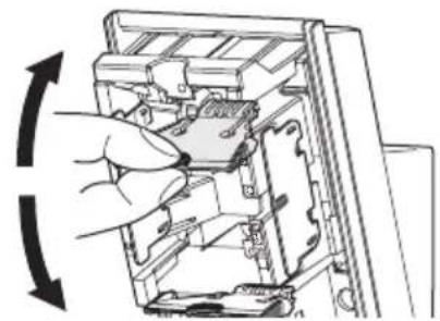
natural_image
Diagram of a hand inserting a component into a device, showing internal structure and rotation arrow (no text or symbols)3 Push the flap until it clicks into position.
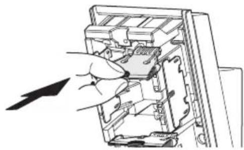
natural_image
Illustration of a hand inserting a component into a device casing (no text or symbols visible)PIR long range detection area reduction
The detection distance in the following table can be limited by combining the positions of the flap.
Use the following table to determine the positions of the upper and lower flaps that set the required max. detection distance.
NOTES:
- The distance may vary due to environmental conditions.
- Always walk test the detector to confirm the detection distance.
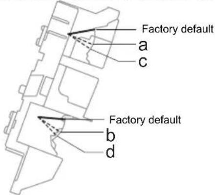
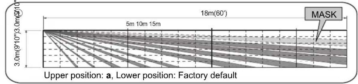
| LowerUpper | Factorydefault | b | d |
| Factorydefault | 24.0 m(80') | N.A. | N.A. |
| a | 118.0 m(60') | 213.0 m(42'8") | N.A. |
| c | N.A. | 310.0 m(32'10") | 46.5 m(22') |
NOTE: Use only the following combinations for the flap settings.
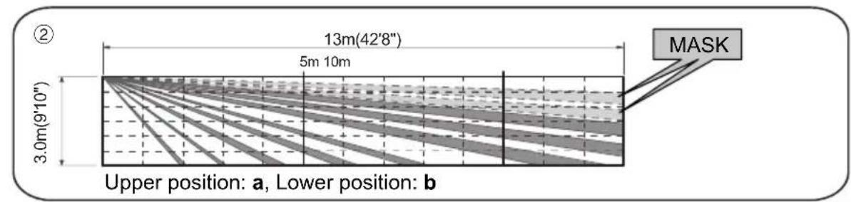
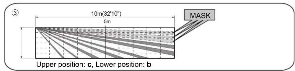
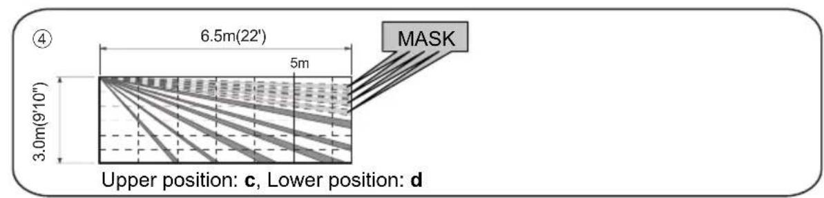
2-3 HOW TO DEACTIVATE THE SHORT RANGE DETECTION AREA
To adjust the SHORT range of detection, set the upper and lower plates as follows:
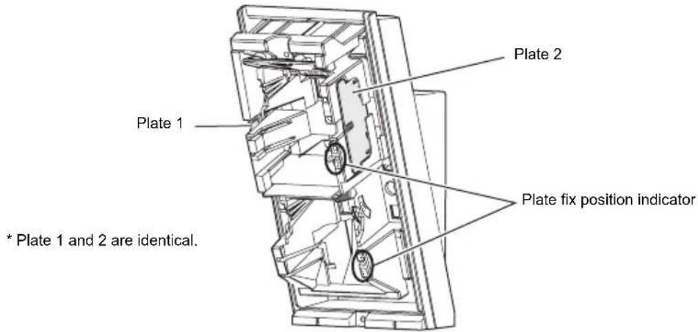
1 Remove the plate.
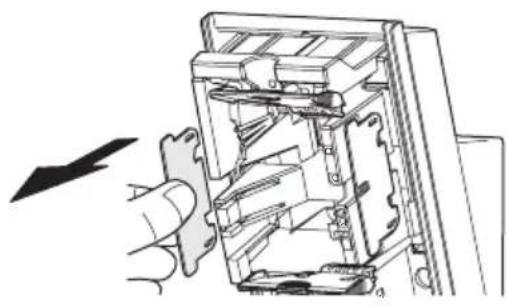
natural_image
Diagram of a hand inserting a component into an internal device (no text or symbols visible)2 Insert the plate into the position determined by the required masking distance until it clicks.
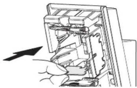
natural_image
Illustration of a hand inserting a component into a device (no text or symbols visible)3 If any plate is not used, place it in the storage position.
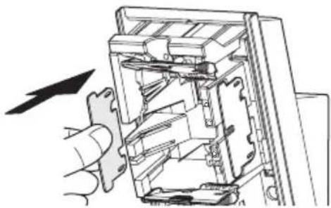
natural_image
Diagram of a hand inserting a gear into a mechanical device (no text or symbols visible)Note>>
Be careful not to lose the plates.
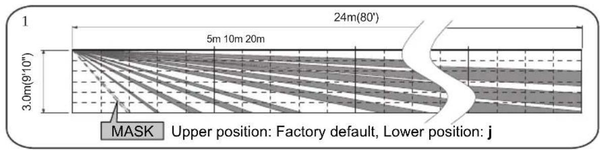
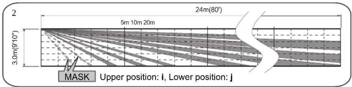
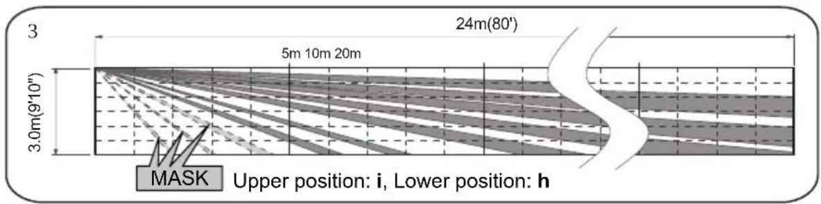
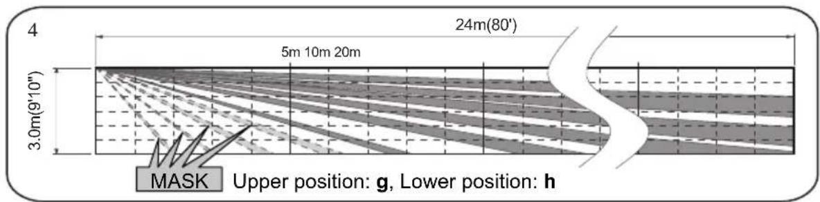
PIR short range detection area deactivation
Use the following table to determine the positions of the plates that set the required masked area.
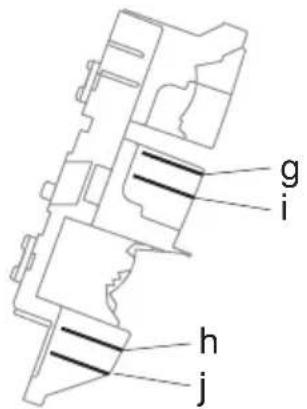
| Lower Upper | Not used | j | h |
| Not used | Factory default | 1 | N.A. |
| i | N.A. | 2 | 3 |
| g | N.A. | N.A. | 4 |
NOTE: Use only the following combinations for the plate settings.
3 INSTALLATION
Use the bracket for normal installation. The unit may be installed directly on the wall, without the bracket, only if the following three conditions are met;
• The mounting height is less than 3m (9'10").
• Horizontal adjustment is not necessary.
• The ground must be level.
3-1 INSTALLING WITH BRACKET
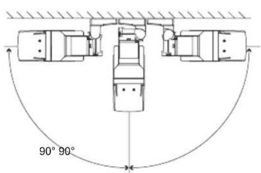
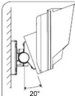
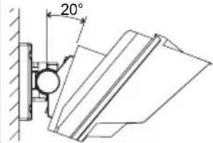
Using the bracket makes it possible to adjust the unit horizontally by ± 90^ . In cases where the ground is uneven and/or not parallel with the base of the unit, it is possible to adjust the unit vertically by ± 20^ .
natural_image
Technical line drawing of a mechanical assembly with a 20-degree angle标注 (no text or symbols beyond the angle marker)Caution>>
Do not change the detection length with bracket.
Use the flaps and plates to adjust the detection length.
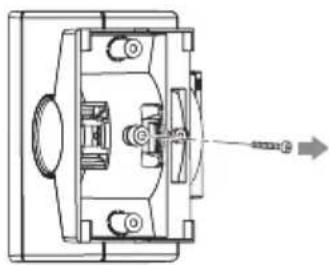
1 Remove the Up-Down lock screw.
natural_image
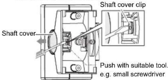
Technical diagram of a mechanical assembly with no visible text or symbols2 Push the shaft cover clip straightly to remove the shaft cover.
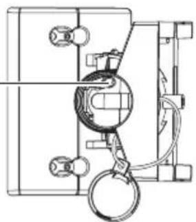
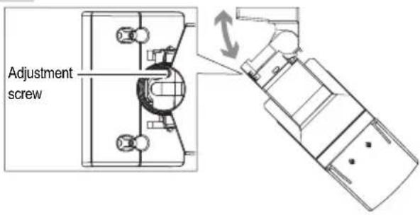
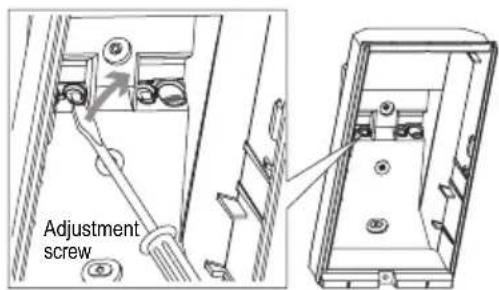
3 Loosen the adjustment screw two turns.
Adjustment screw
Caution>>
Do not loosen the screw too much. It may disassemble.
natural_image
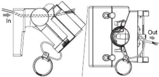
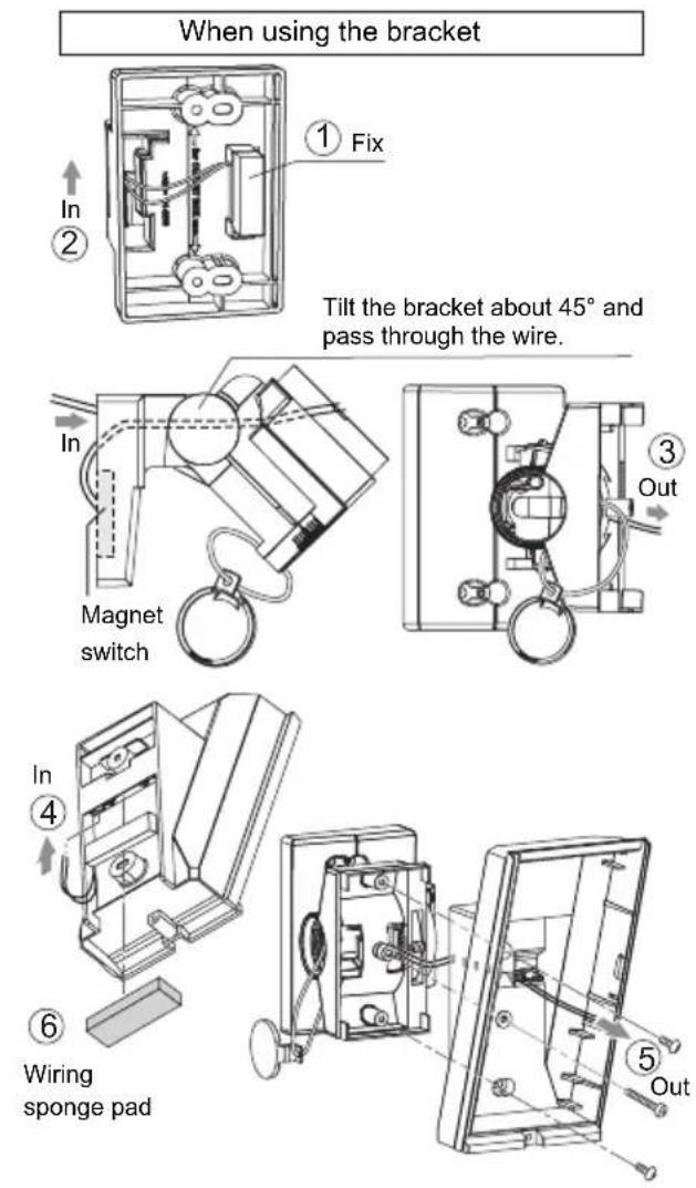
Technical line drawing of a mechanical assembly with no visible text or symbols4 Tilt the bracket about 45^ and pass through the wire.
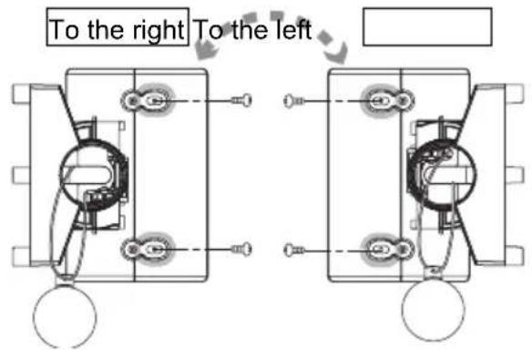
5 Determine the horizontal direction (left or right) of the detector before installing the bracket on the wall.
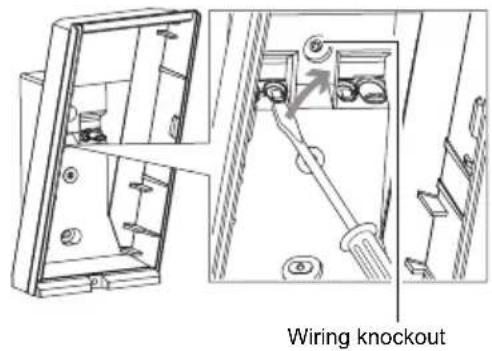
6 Open the wiring knockout.
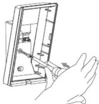
7 Open the Up-Down lock screw knockout for connecting the bracket.
natural_image
Line drawing of a hand using a tool to switch an open electrical panel (no text or symbols visible)Knockout with 4×20 tapping screw (screwkit)
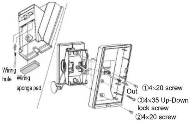
8 Tighten screws ① and ②, adjust the bracket angle (refer to 3-2), then tighten screw ③.
Perform an area check. If re-adjustment is required, loosen screw ③ and change the bracket angle.
After the adjustment is complete, tighten screw ③ again.
9 Tighten the adjustment screw clockwise.
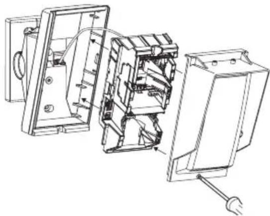
10 Wire to the terminal and install the main unit and lens on the base.
natural_image
Technical line drawing of an open electrical switchgear assembly (no text or labels)11 Install shaft cover into place.
3-2 ADJUSTING THE VERTICAL ANGLE
For best performance, install detector parallel to the ground.
Decide the detection length. To change the detection length, adjust the flap and plate positions. Refer to the 2-2, 2-3 for the details.
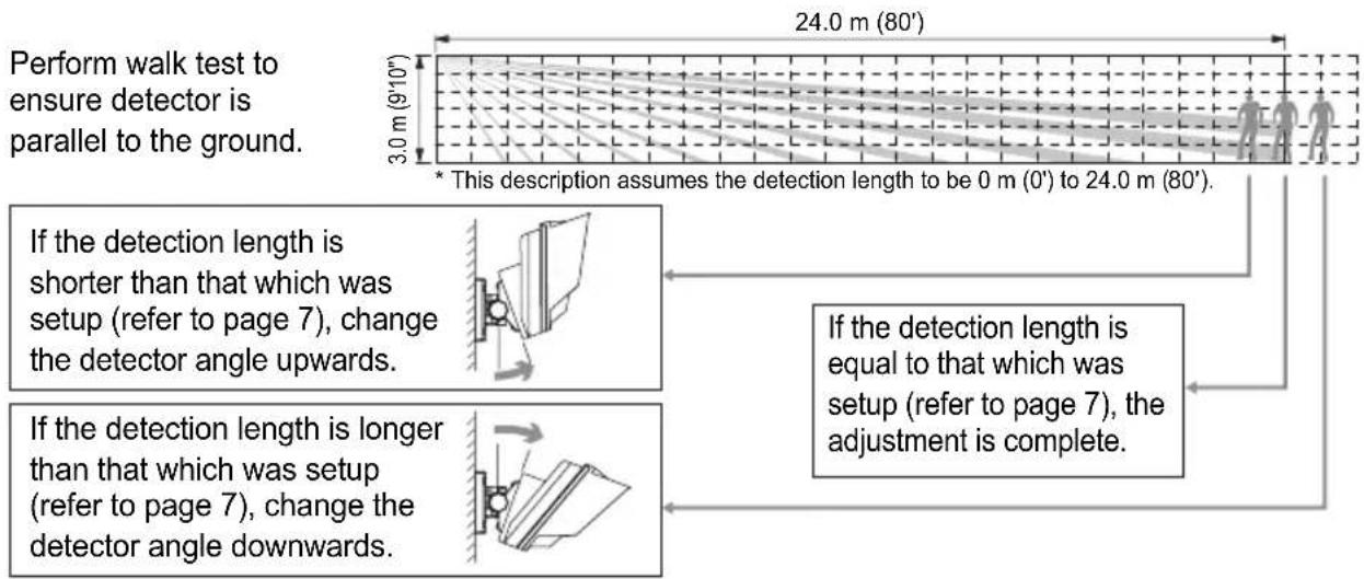
flowchart
graph TD
    A["Perform walk test to ensure detector is parallel to the ground."] --> B["24.0 m (80')"]
    B --> C["3.0 m (9'10'')"]
    C --> D["This description assumes the detection length to be 0 m (0') to 24.0 m (80')"]
    D --> E["If the detection length is shorter than that which was setup (refer to page 7), change the detector angle upwards."]
    E --> F["If the detection length is longer than that which was setup (refer to page 7), change the detector angle downwards."]
    F --> G["If the detection length is equal to that which was setup (refer to page 7), the adjustment is complete."]
Caution>>
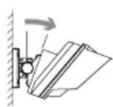
- If the base of the unit is already parallel to the ground, do not change the detection length by tilting the main unit up or down. Refer to 3-1 for the details.
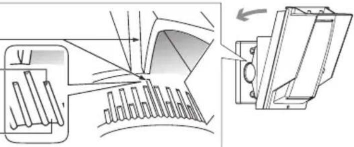
Example (the ground is level) 0^ is the origine.
Adjust 2 clicks (2.5° upward) for 2.5 m (8'2") height installation.
Adjust 1 click (1.25° upward) for 3.0 m (9'10") height installation.
natural_image
Technical diagram showing mechanical assembly with no visible text or symbols3-3 INSTALLING WITHOUT BRACKET
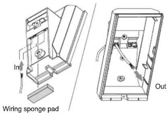
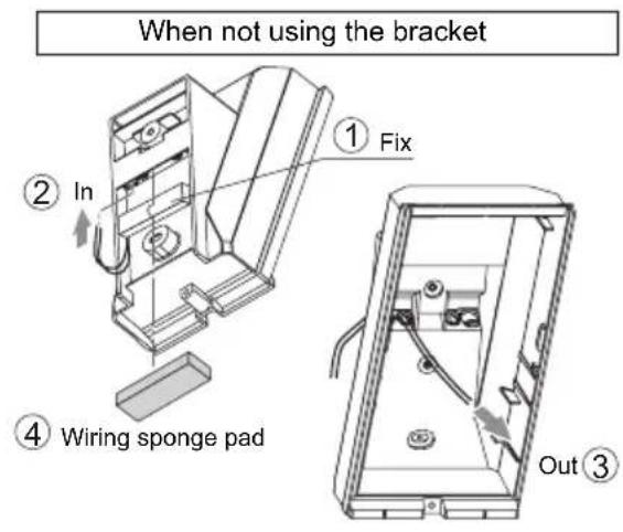
1 Open the wiring knockout with suitable tool e.g. screwdriver.
2 Pull the wire through the base knockout.
3 Fasten the base to the wall.
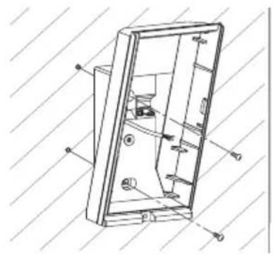
natural_image
Technical line drawing of a door frame with internal components and mounting holes (no text or symbols)4 Install main unit after wiring to the terminal.
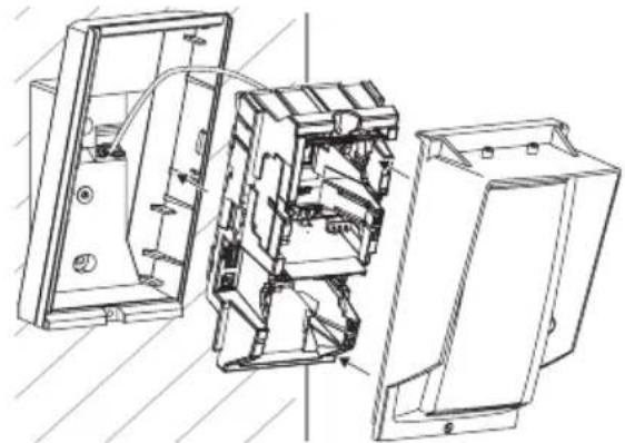
natural_image
Technical line drawing of an open electrical enclosure with internal components (no text or symbols)3-4 WIRING
Power wires should not exceed the following lengths.
| WIRE GAUGE | HX-80N HX-80NAM | |||
| 12 V 14 V | 12 V 14 V | |||
| AWG22 (0.33 mm2) | 160 m(520') | 360 m(1,180') | 140 m(460') | 310 m(1,020') |
| AWG20 (0.52 mm2) | 260 m(850') | 560 m(1,840') | 230 m(750') | 490 m(1,610') |
| AWG18 (0.83 mm2) | 410 m(1,350') | 900 m(2,950') | 360 m(1,180') | 780 m(2,560') |
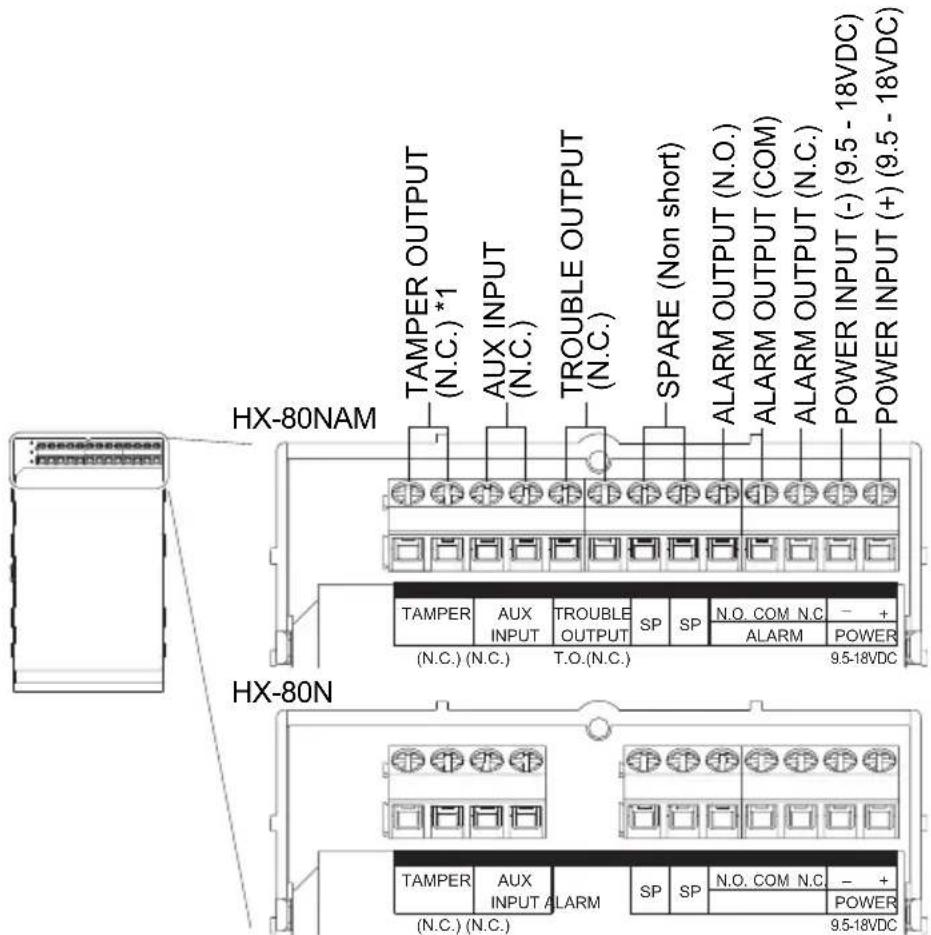
*1: TAMPER terminals to be connected to a 24 hour supervisory loop.
3-5 WALL TAMPER (OPTION)
Universal magnet switch may be mounted as a wall tamper.
Installation space for magnet switch is provided on the back of the main unit and the bracket. Maximum size of an applicable magnet switch: D 9 mm (0.35") × W 40 mm (1.57") × H 9 mm (0.35") Magnet switch is not included.
Main unit
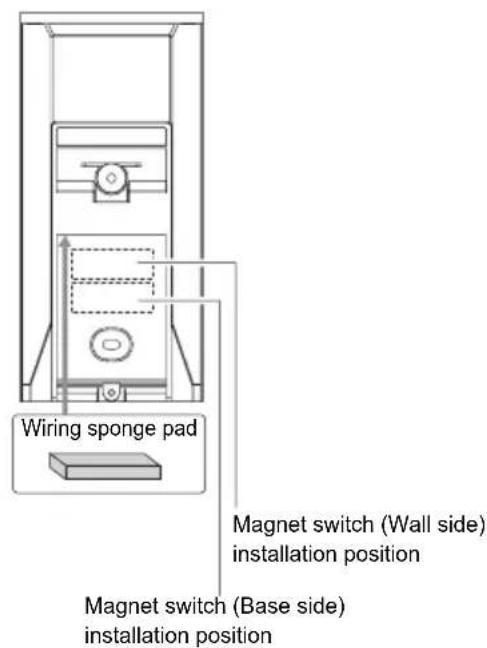
Bracket
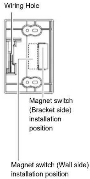
-Installation
1 Install the magnet switch (wall side) to the wall. To determine the installation position, use the "Installation position template" provided on the inside cover of the product package.
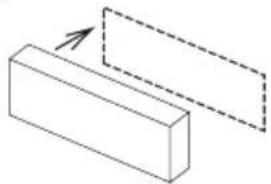
natural_image
Simple line drawing of two rectangular blocks with an arrow pointing to one block (no text or symbols)2 Open the wiring knockout with suitable tool e.g. screwdriver.
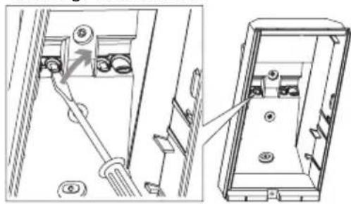
natural_image
Technical line drawing showing a mechanical assembly with a lever and housing, no text or symbols present3 Install the other portion of the magnet switch to the back of the main unit or the bracket. Pull the wiring through the knockouts.
4 Install bracket and the main unit to the walls surface.
5 Connect the magnet switch wiring to the tamper terminal of the main unit.
4 WALK TEST
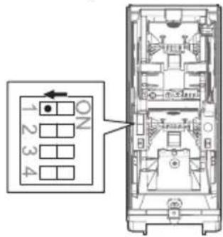
1 Set the DIP switch 1 (LED ON/OFF) to "ON".
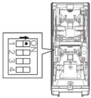
Note>>
The switch is set "ON" by factory default.
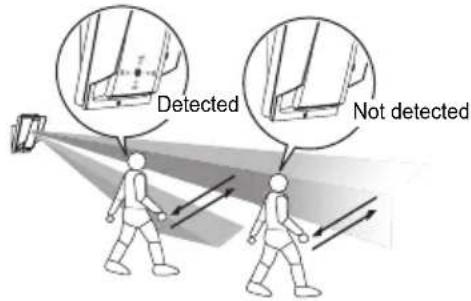
2 Check that the detector detects an object in the intended detection area. The installation has been successful if the LED lights for two seconds after a person walks into the detection area.
Note>>
For the walk test, move more than 1.0 m (3'3") away from the detector.
3 If the LED indication is not required at all times, set the DIP switch 1 (LED ON/OFF) to "OFF".
5 SETTING
| POSITION FUNCTION | |
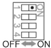
| ON(Factory default) | The LED lights when someone is detected. |
| OFF | The LED does not light even if someone is detected. |
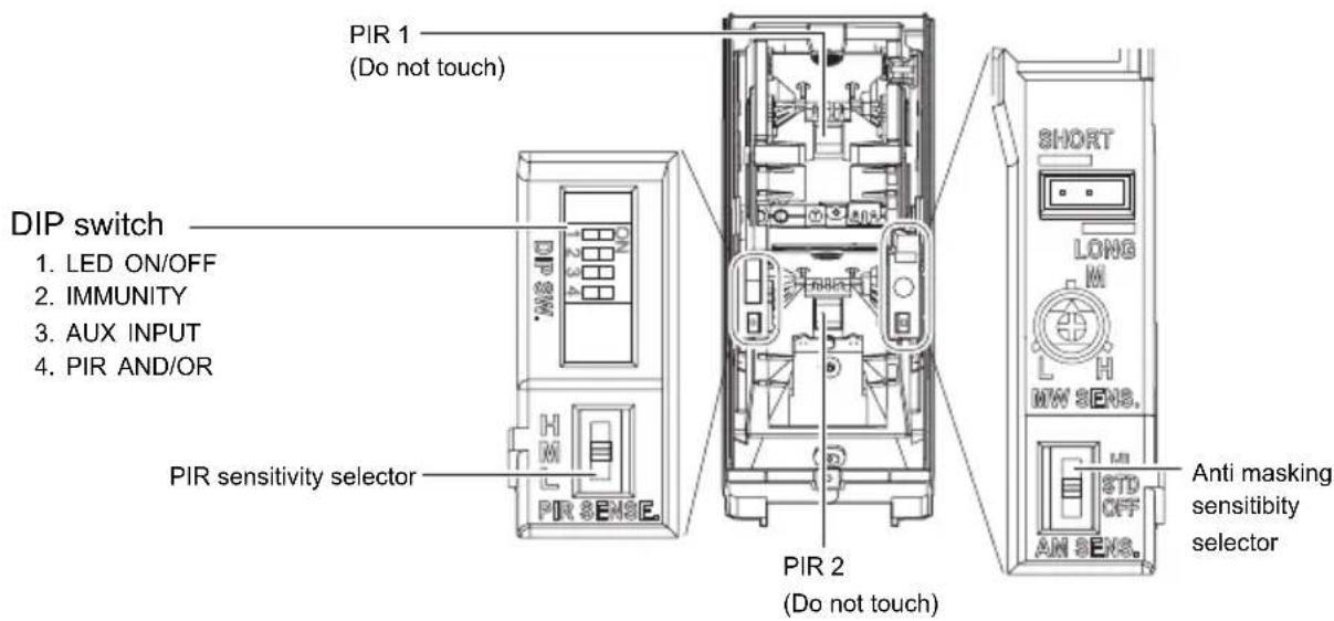
-IMMUNITY DIP switch
2

| POSITION FUNCTION | |
| STD(Factory default) | IMMUNITY logic is not activated. |
| IMMUNITY | IMMUNITY logic is activated. Use this under harsh environment (e.g. vegetation sway). |
-AUX INPUT DIP switch
3
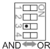
By connecting a secondary unit (another warning sensor), you can extend the detection area and correct false alarms. The secondary unit must have a voltage free N.C. output such as another PIR detector or AIR detector.
Notes>>
- The alarm is only activates if both the main unit and the secondary unit are activated within 60 sec.
- In OR mode, a secondary detector must be fitted. If not fitted, the unit will generate an alarm continuously.
| POSITION FUNCTION | |
| AND (Factory default) | When both the main unit and the secondary detect someone, the alarm is activated. Choose this setting when a secondary unit is not connected. |
| OR | When either the main unit or the secondary detects someone, the alarm is activated. |
-PIR AND/OR DIP switch
4
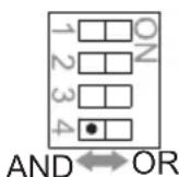
Note>>
"OR" mode is appropriate for the sites that require more detectability rather than false alarm tolerance such as lighting control and camera activation.
| POSITION FUNCTION | |
| AND(Factory default) | An alarm is output when both PIR1 and PIR2 detect an object. |
| OR | An alarm is output when either PIR1 or PIR2 detects an object.Selecting “OR” mode makes detection range longer than “AND” mode.Walk test to readjust the detection range is required when “OR” is selected.Actual adjustment should be conducted by adjusting the bracket angle.OR mode only |
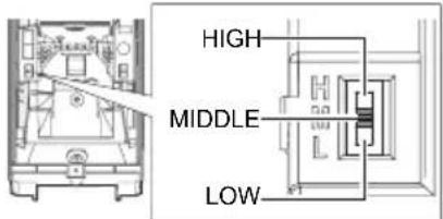
| POSITION FUNCTION | |
| HIGH High | sensitivity |
| MIDDLE (Factory default) | Middle sensitivity |
| LOW Low | sensitivity |
-ANTI-MASKING SENSITIVITY
ANTI-MASKING
SENSITIVITY SELECTOR
HX-80N
HX-80NAM
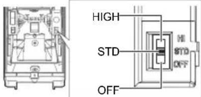
| POSITION FUNCTION | |
| HIGH High | sensitivity |
| STD(Factory default) | Normal sensitivity |
| OFF Disabled | |
Caution>>
After closing the cover, do not leave any objects closer than 1 meter from the unit.
6 LED INDICATION
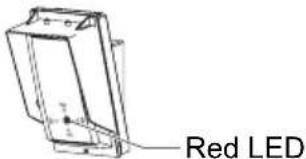

| DETECTOR CONDITION | LED INDICATOR (RED ONLY) | |
| Warm-up |  Blinks for approx. 60 sec. Blinks for approx. 60 sec. | |
| Alarm |  Lights for 2 sec. Lights for 2 sec. | |
| Trouble output (HX-80NAM only) | Anti-Masking booting(Anti-Masking start up) | 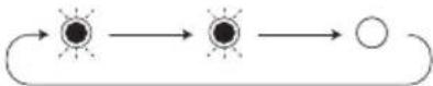 Blinks 2 times and goes off for 5 sec. and then repeats for 180 sec. Blinks 2 times and goes off for 5 sec. and then repeats for 180 sec. |
| Masking detection |  Blinks 3 times and goes off for 3 sec. and then repeats. Blinks 3 times and goes off for 3 sec. and then repeats. | |
7 SPECIFICATIONS
7-1 SPECIFICATIONS
| Model HX-80N HX-80NAM | ||
| Detection method Passive infrared | ||
| PIR Coverage 24.0 m × 2.0 m (80' × 6'7") narrow / 20 zones | ||
| PIR distance limit 6.5 m, 10.0 m, 13.0 m, 18.0 m (22', 33', 42', 59') | ||
| Detectable speed 0.3 m/s – 1.5 m/s (1'/s – 4'11"/s) | ||
| Sensitivity 2.0°C (3.6°F) at 0.6 m/s | ||
| Power input 9.5 – 18 V DC | ||
| Current draw | 35 mA (max.)at 12 V DC | 40 mA (max.)at 12 V DC |
| Alarm period 2.0 ±1 sec. | ||
| Warm-up period Approx. 60 sec. (LED blinks) | ||
| Alarm output Form C 28 V DC 0.2 A (max.) | ||
| Tamper output N.C. 28 V DC, 0.1 A (max.) N.C. open when cover removed. | ||
| Trouble output – N.C. 28 V DC, 0.1 A (max.) | ||
| Aux input | N.C. 28 V DC, 0.1 A (max.) | |
| LED indicator | Red: Warm-up, Alarm | Red: Warm-up, Alarm, Trouble |
| RF interference | No alarm 10 V/m | |
| Operating temperature | -20 – +60°C (-4 – +140°F) | |
| Environment humidity | 95% max. | |
| Weatherproof | IP55 | |
| Mounting | Wall | |
| Mounting height | 2.5 – 3.0 m (8'2" – 9'10") | |
| Bracket adjust angle | Vertical: ±20° Horizontal: ±95° | |
| Weight | 720 g (25.4 oz.) | |
| Accessories | Bracket, Screw (4 × 20 mm) × 4 | |
*Specifications and designs are subject to change without prior notice.
7-2 DIMENSIONS
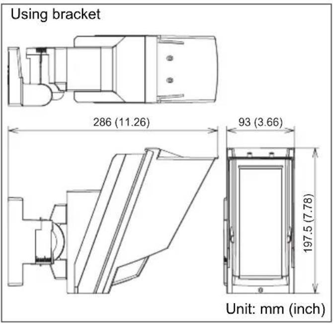
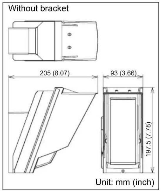
The HX-80N series is only a part of a complete system, therefore we cannot accept complete responsibility for any damages or other consequences resulting from an intrusion.

OPTEX
OPTEX CO., LTD. (JAPAN)
(ISO 9001 Certified)
(ISO 14001 Certified)
5-8-12 Ogoto Otsu
Shiga 520-0101
JAPAN
TEL:+81-77-579-8670
FAX:+81-77-579-8190
URL:http://www.optex.co.jp/e/
OPTEX INCORPORATED (USA)
TEL:+1-909-993-5770
Tech:(800)966-7839
URL:http://www.optexamerica.com/
OPTEX (EUROPE) LTD. (UK)
TEL:+44-1628-631000
URL:http://www.optex-europe.com/
OPTEX SECURITY SAS (FRANCE)
TEL:+33-437-55-50-50
URL:http://www.optex-security.com/
OPTEX SECURITY Sp. z o. o. (POLAND)
TEL:+48-22-598-06-55
URL:http://www.optex.com.pl/
OPTEX KOREA CO., LTD. (KOREA)
TEL:+82-2-719-5971
URL:http://www.optexkorea.com/
OPTEX (DONGGUAN) CO., LTD. SHENZHEN OFFICE (CHINA)
TEL:+86-755-33302950
URL:http://www.optexchina.com/


- CONTENTS
- INSTALLATION PRECAUTIONS
- 1-1 BEFORE INSTALLATION
- 1-2 PARTS IDENTIFICATION
- 1-3 KNOCKOUTS
- DETECTION AREA
- 2-1 OUTLINE OF DETECTION AREA
- 2-2 HOW TO REDUCE THE LONG RANGE DETECTION AREA
- Pull out the flap.
- Note>>
- Move the flap to the position that corresponds with the desired detection distance.
- Push the flap until it clicks into position.
- PIR long range detection area reduction
- NOTES:
- 2-3 HOW TO DEACTIVATE THE SHORT RANGE DETECTION AREA
- Remove the plate.
- Insert the plate into the position determined by the required masking distance until it clicks.
- If any plate is not used, place it in the storage position.
- PIR short range detection area deactivation
- INSTALLATION
- 3-1 INSTALLING WITH BRACKET
- Caution>>
- 3-2 ADJUSTING THE VERTICAL ANGLE
- 3-3 INSTALLING WITHOUT BRACKET
- 3-4 WIRING
- 3-5 WALL TAMPER (OPTION)
- -Installation
- WALK TEST
- SETTING
- -IMMUNITY DIP switch
- -AUX INPUT DIP switch
- Notes>>
- -PIR AND/OR DIP switch
- LED INDICATION
- SPECIFICATIONS
- 7-2 DIMENSIONS
- OPTEX
- OPTEX CO., LTD. (JAPAN)
- OPTEX INCORPORATED (USA)
- OPTEX (EUROPE) LTD. (UK)
- OPTEX SECURITY SAS (FRANCE)
- OPTEX SECURITY Sp. z o. o. (POLAND)
- OPTEX KOREA CO., LTD. (KOREA)
- OPTEX (DONGGUAN) CO., LTD. SHENZHEN OFFICE (CHINA)
Brand : OPTEX
Model : HX-80NAM
Category : Motion detector