USER MANUAL PMW-1000 SONY
1st Edition (Revised 10)
Table of Contents
Chapter 1 Overview
Features......6
Features of this unit 6
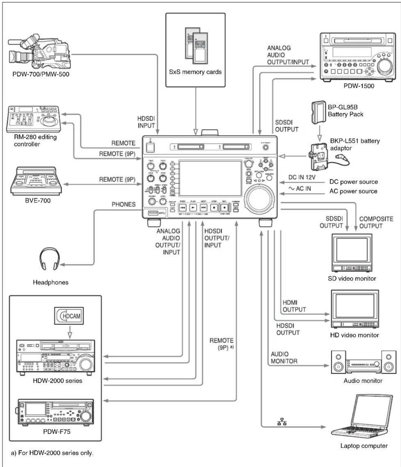
System Configurations ......9
Chapter 2 Names and Functions of Parts
Front Panel ....10
Display screen 14
Rear Panel 19
Chapter 3 Preparations
Preparing Power Sources ....22
Supplying power.... 22
Attaching a battery pack.... 22
Initial Setup 24
Connections and Settings 25
Connections for Content Browser and non-Sony nonlinear editors.... 25
Connections for cut editing 27
Using the editing functions of the recorder (controlling through REMOTE(9P) connector) 30
Connections for pool coverage.... 31
Synchronization Reference Signals....32
Setting System Frequency....33
Setting Timecode....33
Superimposed Text Information....35
Basic Operations of the Function Menu....37
Function menu operations 37
Function menu settings.... 37
Handling Memory Cards ....40
About memory cards .... 40
Inserting/removing an SxS memory card.... 41
Switching between SxS memory cards 42
Formatting (initializing) an SxS memory card.... 42
Handling an External Storage 43
Using the external storage 43
Removing the external storage 44
Chapter 4 Recording, Playback and Copy
Recording.... 45
Preparations for recording 45
Carrying out recording.... 45
Continuing to record while exchanging memory cards (relay recording)....46
Recording with the HDSDI remote control function.... 47
Handling of SxS memory cards when recording does not end normally (salvage functions).... 47
Playback.... 48
Playback operation.... 49
Playback operations using thumbnails.... 52
Copying 52
Overview....52
Copy operations 53
Chapter 5 Operations in Clip List Screens
Overview.... 55
Switching between display screens 55
Information and controls in clip list screens.... 56
Clip Menu 59
Clip F Menu....60
Clip Operations.... 61
Selecting clips.... 61
Searching with thumbnails 61
Playing a clip by thumbnail search.... 62
Setting clip flags 63
Locking (write-protecting) clips 63
Deleting clips.... 63
Copying clips....64
Setting the index picture frame.... 64
EDL Editing 65
What is EDL editing? 65
Creating and editing EDLs 66
Checking the media information 68
Formatting (initializing) SxS memory cards.... 68
Chapter 6 File Operations
Overview....70
Directory structure.... 70
File operation restrictions.... 70
FTPS protocol support.... 70
FTP File Operations....71
Making FTP connections.... 71
Command list 72
CIFS File Operations ....75
Making CIFS connections 75
Items in the basic menu 77
Basic menu operations....80
Menu bank operations (menu items B01 to B13)....82
Items in the extended menu....83
Extended menu operations 94
Maintenance Menu....95
Items in the maintenance menu 95
Maintenance menu operations.... 98
Appendix
Important Notes on Operation....101
About the LCD panel 101
Network 101
Periodic Maintenance....102
Operating hours meter 102
Troubleshooting ....103
Alarms 103
Error messages 109
Specifications 110
Using UMID Data.... 114
Ancillary Data.... 116
Ancillary data in HDSDI/SDSDI signals 116
Ancillary data in MXF files.... 116
Closed caption data.... 117
Trademarks and Licenses 118
Trademarks 118
MPEG-4 visual patent portfolio license 118
About IJG (Independent JPEG Group).... 118
Character display software "iType" 118
Open source software licenses.... 118
Obtaining GPL/LGPL/GPL V3 licensed software 118
Index 119
Overview
Chapter
1
Features
The PMW-1000 is a full-HD (1920 × 1080 and 1280 × 720) memory recorder.
It features an enhanced networking and other IT functions, and is highly compatible with nonlinear editing systems and network production systems, enabling efficient file-based operation.
The unit can be used as a player for video editing and program output, and as a recorder for nonlinear editing. For these applications, the unit can be connected via its SDI I/O connectors to earlier nonlinear editors, monitors, and video equipment with SDI interfaces.
It has a compact, lightweight body for easy portability outdoors, and can be powered from any of three power sources: AC, DC, or battery ^1) power.
1) BKP-L551 Battery Adaptor is required.
Features of this unit
The principal features of this unit are as follows.
Multiple codecs
MPEG HD422 codec
The MPEG HD422 codec provides video compression complied with the MPEG-2 422P@HL standard. It enables HD 4:2:2 (50 Mbps) digital component file recording in the 1080i (1080 effective scanning lines, interlaced) format currently in use by many broadcast facilities. Uncompressed PCM recording of 24-bit 48 kHz audio enables 8-channel audio recording at high sound quality.
MPEG-4 AVC/H.264 codec
This unit supports the XAVC ^™ format complied with the MPEG-4 AVC/H.264 codec as a recording format and enables HD 4:2:2 digital component file recording (Intra 100 Mbps, Long 50/35/25 Mbps) in 1080i/720P format.
Uncompressed PCM recording of 24-bit 48 kHz audio enables 8-channel audio recording at high sound quality.
Recording and playback functions
Support for MPEG/XAVC/SD with multiple codecs
In addition to the MPEG HD422 codec and XAVC MPEG-4 AVC/H.264 codec, this unit supports the MPEG HD420 codec, allowing HD operation across a wide range of recording times and application objectives.
The unit is also capable of DVCAM codec recording and IMX playback (30/40/50 Mbps).
Support for multiple frame frequencies
This unit can record and play multiple frame frequencies at 1080 (59.94i, 50i, 29.97P, 25P and 23.98P) or 720 (59.94P and 50P) with MPEG HD422 codec and XAVC codec.
SD up-convert function
The unit can output HD signals while playing SxS memory cards recorded as SD, allowing SD material to be utilized in an HD environment.
HD down-convert function
The unit is provided with a downconvert function. HD playback signals can be downconverted to SD signals and then output as SDSDI or composite signals. This allows you to use SD nonlinear editors and monitors for editing and program output.
HDSDI remote recording
HDSDI connections can be made to camcorders with remote HDSDI support (PDW-700 XDCAM HD422 camcorder, HDW-730/730S/750/790/F900R HDCAM camcorders) to enable recording synchronized to REC and STOP operations on the camcorder.
1080/720 cross-conversion
This unit supports cross-conversion output. It can output 720 while playing media recorded as 1080, and output 1080 while playing media recorded as 720.
Recording of proxy AV data
Proxy AV data is a low-resolution (1.5 Mbps video, 64 kbps per audio channel), MPEG-4 based version of a full resolution data stream. Whenever this unit records full resolution MPEG HD422 data, it simultaneously generates and records low-resolution proxy AV data. Because of its small size, proxy AV data can be transferred quickly over computer networks, easily edited in the field with laptop computers, and readily used in a wide variety of applications, such as content management on small-scale servers.
High-speed searches with the jog and shuttle dials
The jog and shuttle dials can be used to find scenes inside clips, in the same way as the jog and shuttle dials on conventional VTRs.
In jog and variable modes, you can search in field units at from -2 to +2 times normal speed. In shuttle mode, you can perform high-speed searches at either ±20 times normal speed. High-speed F.FWD and F.REV searching is possible at ±35 times normal speed.
Convenient playback and searching
Like previous products in the XDCAM series, this unit supports a number of convenient search functions, including, thumbnail searches, essence marks searches, and expand searches.
Thumbnail searches: The unit creates thumbnails from the first frame of each generated clip, and displays them in thumbnail lists on the color LCD or an external monitor. You can cue up clips very easily by simply by selecting them from thumbnail lists.
Essence mark searches: Essence marks can be recorded at any scene during or after recording. Lists of these marks can be displayed on the color LCD or an external monitor, allowing you to quickly find scenes that were marked for later reference.
Expand searches: This function allows you to look inside the clip selected in a thumbnail screen, or inside the segment from a selected essence mark to the next essence mark. The selection range is divided into 12 equal blocks, and the first frames of those blocks are displayed as thumbnails. By checking the thumbnails, you can easily find the scene you want.
Usability features
AC, DC, and battery 1) power support
The unit can be used even where AC power is not available, for example outdoors or in cars or helicopters.
1) BKP-L551 Battery Adaptor is required.
Color LCD display
The unit is equipped with a 16:9, 4.3-inch color LCD which allows you to check the contents of the SxS memory card and use the menu system without connecting an external monitor.
Built-in speakers
The unit features built-in speakers, allowing you to check recorded audio. You can check your clips and editing results on the color LCD and speakers even when no monitors or separate speakers are available.
IT friendly
Equipped with network connector
The unit features a Gigabit Ethernet connector as standard equipment. Via this connector, you can connect the unit to computers and networks to enable listing of the video, audio, and metadata files recorded on the SxS memory card, and rapid file transfers. Support for FTP commands makes it easy to carry out network file transfers from remote locations.
Use network within a secure environment.
Supports SNMP for maintenance and service
This unit supports Sony's SNMP-based remote maintenance and monitoring software. This software allows you to monitor the status of the hardware via a TCP/IP network in real time, and to record the results in a status log.
Use SNMP within a secure environment.
Supports a variety of interfaces
This unit supports the following interfaces.
• HDSDI video, 8-channel audio input and output
- SDSDI video, 8-channel audio input and output (the SD/HDSDI INPUT connector doubles as an SDSDI/HDSDI input connector)
- HDMI output
- SD composite output
- Analog audio 2-channel input and output
- Remote
- RS-422A (D-sub 9-pin × 1)
Copying files between a USB external storage and an SxS memory card
The unit is provided with a USB 3.0 interface on the front panel, allowing you to connect even a USB mass storage class (3 GB to 2 TB) device and use it as an external storage. You can copy clips and clip lists between this external storage and an SxS memory card.
Software Downloads
When the unit is used with a PC connection, download any device drivers, plug-ins, and application software you require from the following websites.
Sony Professional products website:
U.S.A. http://pro.sony.com
Canada http://www.sonybiz.ca
Latin America http://sonypro-latin.com
Europe http://www.pro.sony.eu/pro
Middle East, Africa http://sony-psmea.com
System Configurations
flowchart
graph TD
    A["HDW-2000 series"] --> B["HDW-F75"]
    B --> C["Headphones"]
    C --> D["RM-280 editing controller"]
    D --> E["PDW-700/PMW-500"]
    E --> F["SxS memory cards"]
    F --> G["Analog audio output/input"]
    G --> H["PDW-1500"]
    H --> I["BP-GL95B Battery Pack"]
    I --> J["BKP-L551 battery adaptor"]
    J --> K["DC power source AC power source"]
    K --> L["SDSIDI OUTPUT"]
    L --> M["COMPOSITE OUTPUT"]
    M --> N["SD video monitor"]
    N --> O["HD video monitor"]
    O --> P["Audio monitor"]
    P --> Q["Laptop computer"]
    C --> R["HDW-2000 series"]
    R --> S["HDW-F75"]
    S --> T["Headphones"]
    T --> U["ARM 9P"]
    U --> V["HDSDI INPUT"]
    V --> W["HDSDI OUTPUT/INPUT"]
    W --> X["HDSDI OUTPUT (9P) a"]
    X --> Y["Remote (9P)"]
    Y --> Z["Remote"]
    Z --> AA["HDSDI INPUT"]
    AA --> AB["HDSDI INPUT"]
    AB --> AC["HDSDI OUTPUT"]
    AC --> AD["HDSDI OUTPUT (9P) a"]
    AD --> AE["HDSDI OUTPUT/INPUT"]
    AE --> AF["HDSDI OUTPUT/INPUT"]
    AF --> AG["HDSDI OUTPUT"]
    AG --> AH["HDSDI OUTPUT/INPUT"]
    AH --> AI["HDSDI OUTPUT/INPUT"]
    AI --> AJ["HDSDI OUTPUT/INPUT"]
    AJ --> AK["HDSDI OUTPUT/INPUT"]
    AK --> AL["HDSDI OUTPUT/INPUT"]
    AL --> AM["HDSDI OUTPUT/INPUT"]
    AM --> AN["HDSDI OUTPUT/INPUT"]
Names and Functions of Parts
Chapter
2
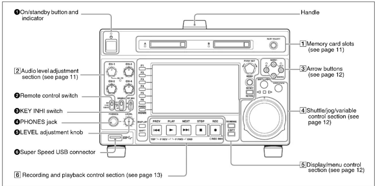
Front Panel
The names and symbols of buttons and knobs on the front panel are color coded according to function.
White: Function when the button or knob is operated independently.
Orange: Function when the button is operated with the SHIFT button held down.
Blue: Function related to thumbnail operations.
When the POWER switch on the rear panel is in the I (on) position, or when DC power is connected to the DC IN 12V connector on the rear panel, this switches the unit between the operating state (the indicator is lit green) and the standby state (the indicator is lit red).
When you press this button with the indicator lit red and holding it down for a short time (0.25 seconds or longer), the indicator changes to lit green, and the unit enters the operating state.
When you press this button with the indicator lit green and holding it down for a longer time (1 second or longer), the indicator changes to flashing green and then lit red, and the unit enters the standby state.
When using this unit, normally leave the rear panel POWER switch in the I position, and use this button to switch the unit between the operating state and standby state.
② Remote control switch
Different positions of the switch allow different operations as follows.
NET: Enables access to the network. The indicator lights when an external network device is being accessed. In this state, it is not possible to perform recording and playback on this unit using its buttons/dials.
LOCAL: Enables operation from the front panel.
With this unit accessing a network device, setting the remote control switch to “LOCAL” displays a dialog asking for your confirmation about network disconnection. To disconnect, press the PUSH SET knob. To not disconnect, set the remote control switch to “NET”.
REMOTE: Enables remote control of this unit from the following devices:
• Devices connected to the REMOTE(9P) connector
- Devices connected to the SD/HDSDI INPUT connector with SDI remote control functions Use setup menu item 214 REMOTE INTERFACE to select which of the connectors is used for remote control.
When you are going to remote-control this unit, you can use setup menu item 006 LOCAL FUNCTION ENABLE to enable or disable the buttons and switches in the recording and playback control section of the unit.
③KEY INHI switch
This turns key operation inhibit mode on or off.
④ PHONES jack
The jack is a standard stereo jack. Connect stereo headphones to monitor the audio during recording, playback, and editing. (Non-audio signals are muted.) The monitored channel is selected with MONITR L and MONITR R on the HOME page of the function menu (see page 37).
⑤LEVEL (volume) adjustment knob
Adjust the volume of headphones or speakers with the knob. You can also cause this to simultaneously adjust the output volume from the AUDIO MONITOR R, L connectors on the rear panel. To do this, set setup menu item 114 AUDIO MONITOR OUTPUT LEVEL to "var".
⑥ Super Speed USB connector (USB 3.0)
Connect the USB connector of the external storage device.
1 Memory card slots
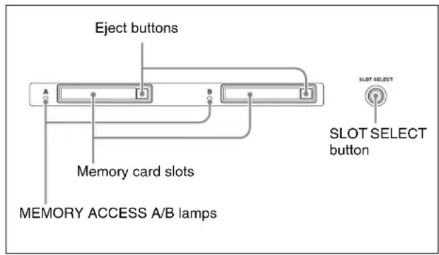
See “Handling Memory Cards” on page 40 for more information about memory card operations.
2 Audio level adjustment section
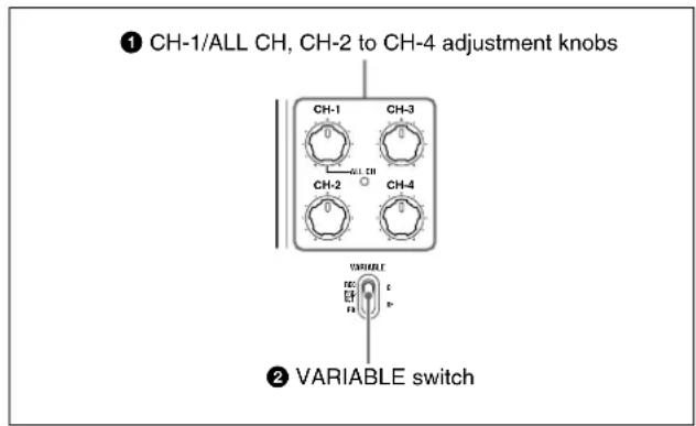
①CH-1/ALL CH, CH-2 to CH-4 (audio level) adjustment knobs
Depending on the setting of the VARIABLE switch, these adjust the input audio or playback audio levels of channels 1 to 4.
You can adjust levels of channels 5 to 8 using the function menu. For details, see page 38.
By the setting of setup menu item 131 AUDIO VOLUME, you can enable the CH-1/ALL CH adjustment knob to simultaneously adjust all eight channels. When this simultaneous adjustment is enabled, the ALL CH indicator lights.
②VARIABLE (audio level adjustment selector) switch
This selects whether input audio levels or playback audio levels are adjusted by the CH-1/ALL CH and CH-2 to CH-4 adjustment knobs for channels 1 to 4, or by the function menu setting for channels 5 to 8.
REC: Adjust the input audio levels. The playback audio levels are fixed at their preset values.
PRESET: The audio levels are fixed at their preset values.

PB: Adjust the playback audio levels. The input audio levels are fixed at their preset values.
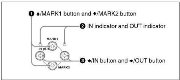
The four arrow buttons are also used as the MARK1 button, MARK2 button, IN button, and OUT button. The correspondence with these buttons is as follows.
▲ button: MARK1 button
↓ button: MARK2 button
← button: IN button
→ button: OUT button
You can use these buttons for thumbnail selection, menu setting operations, setting IN/OUT points, and so on.
flowchart
graph TD
    A["① ↕/MARK1 button and ↕/MARK2 button"] --> B["② IN indicator and OUT indicator"]
    B --> C["③ ←/IN button and →/OUT button"]
    C --> D["MARK1"]
    C --> E["MARK2"]
    D --> F["IN OUT"]
    E --> G["→"]
When the clip list screen is shown on the display, you can use these for thumbnail selection.
During recording or STILL (still picture mode), a shot mark 1 or shot mark 2 is recorded as an essence mark when you press the PUSH SET knob with the ♠/MARK1 or ♦/MARK2 button held down.
Essence marks can be deleted in the chapter thumbnail screen (see page 62).
②IN indicator and OUT indicator
Light or flash as follows when you set IN and OUT points in the clip to copy only the part defined by the IN and OUT points (see page 54).
IN indicator: When an IN point is set, this lights. If an attempt is made to set the IN point after a recorded OUT point, this flashes.
OUT indicator: When an OUT point is set, this lights. If an attempt is made to set the OUT point before a recorded IN point, this flashes.
When the clip list screen is shown on the display, you can use these for thumbnail selection.
An IN or OUT point is set when you press the PUSH SET knob with the ◀/IN or ▶/OUT button held down. The IN or OUT point setting is deleted when you press the RESET/RETURN button with the ◀/IN or ▶/OUT button held down.
4 Shuttle/jog/variable control section
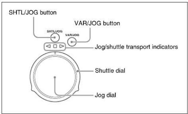
For details of playback operations with these buttons and dials, see "Playback operation" on page 49.
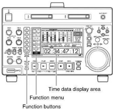
5 Display/menu control section
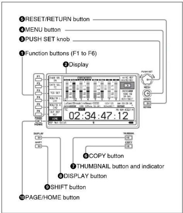
These buttons are enabled when the function menu (see page 37) is visible. Each press of a button changes the setting of the corresponding item in the menu.
For convenience, this manual refers to these buttons as buttons F1 to F6, in order from the top.
②Display
Displays menus, audio level meters, and data such as time data or clip information. The DISPLAY button lets you switch to the video monitor display.
For details, see "Display screen" on page 14.
③ PUSH SET knob
Use for menu and clip list screen operations. Turn the knob to select items, and press it to confirm the selection. This button is also used to set numerical and timecode values.
See “Clip Operations” (page 61) for more information about how to use the thumbnail screens.
Displays the setup menu or the clip list screen menu. The setup menu appears when no clip list screen is visible. The same information is also superimposed on the display on a monitor connected to the HDMI OUT connector of the unit. Press once more to return to the original display.
See “Clip Operations” (page 61) for more information about how to use the thumbnail screens.
Functions as the RESET button or the RETURN button.
RESET button: Reset counters or the setting values of the timecode generator. This button is also used to abort or cancel setup menu and thumbnail search operations.
RETURN button: In setup menu and clip list screens, returns to the previous procedure.
Displays the Clip Copy screen (see page 53) when pressed while the clip list screen is shown on the display.
When this button is pressed when the basic operation screen or video monitor screen is displayed, a list of clips or EDLs saved on the currently selected media is displayed. (That is, the current screen is switched to a clip list screen.) When pressed again, returns to the basic operation screen or the video monitor screen.
See “Clip Operations” (page 61) for more information about how to use the thumbnail screens.
Each press of this button switches between the basic operation screen and video monitor screen (see page 14). When the clip list screen is shown on the display, this button switches the display screen between thumbnails view and details view.
Switches between functions for any button with two functions.
⑩PAGE/HOME button
When pressed alone functions as the PAGE (page switching) button. When pressed together with the SHIFT button, functions as the HOME button.
PAGE button: Displays the function menu, if it is not already visible. (The most recently displayed page of the function menu appears.)
HOME button: When pressed with the function menu visible, returns to the HOME page of the function menu.
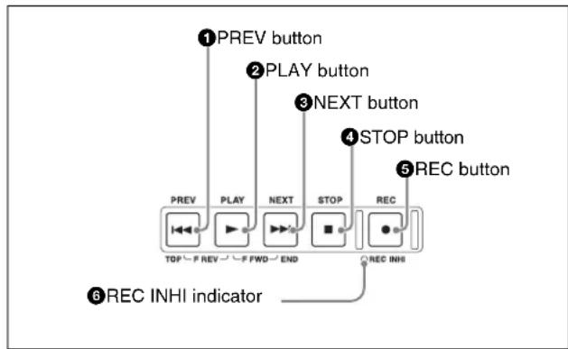
6 Recording and playback control section
flowchart
graph TD
    A["1 PREV button"] --> B["2 PLAY button"]
    B --> C["3 NEXT button"]
    C --> D["4 STOP button"]
    D --> E["5 REC button"]
    E --> F["6 REC INHI indicator"]
    style A fill:#f9f,stroke:#333
    style B fill:#f9f,stroke:#333
    style C fill:#f9f,stroke:#333
    style D fill:#f9f,stroke:#333
    style E fill:#f9f,stroke:#333
    style F fill:#ccf,stroke:#333
Press this button, turning it on, to show the first frame of the current clip. While the first frame of a clip is shown, pressing this button jumps to the beginning of the previous clip. This button is also used together with other buttons for the following operations.
Reverse direction high-speed search: Hold down the PLAY button, and press this button. A high-speed search in the reverse direction is carried out.
Displaying the first frame of the first clip: Hold down the SHIFT button, and press this button.
To start playback, press this button, turning it on.
When this button is pressed during recording, recording stops and the unit enters stop mode. If you do not want to stop recording when this button is pressed, set setup menu item 145 MODE KEY ENABLE DURING RECORDING to "stop".
Press this button, turning it on, to jump to the next clip, and show the first frame. This button is also used together with other buttons for the following operations.
Forward direction high-speed search: Hold down the PLAY button, and press this button. A high-speed search in the forward direction is carried out.
Displaying the last frame of the last clip: Hold down the SHIFT button, and press this button.
To stop recording or playback, press this button, turning it on. The frame at the stop point appears.
Note
This button flashes when setup menu item 105
REFERENCE SYSTEM ALARM is set to "on" and the correct reference video input signal (as specified by OUT REF on the HOME page of the function menu) is not being input.
To start recording, hold down this button, and press the PLAY button. The recording takes place on an unrecorded part of the SxS memory card.
To stop recording, press the STOP button.
To monitor in EE mode
You can press this button from stop mode to monitor input signals in EE mode. The button lights when pressed. Press the STOP button to return to the original video.
You can also press this button during playback and searches. EE mode playback continues for as long as the button is held down.
⑥REC INHI (recording inhibit) indicator
This lights when an SxS memory card with recording inhibited or a non-recordable media is loaded.
Display screen
Basic operation screen
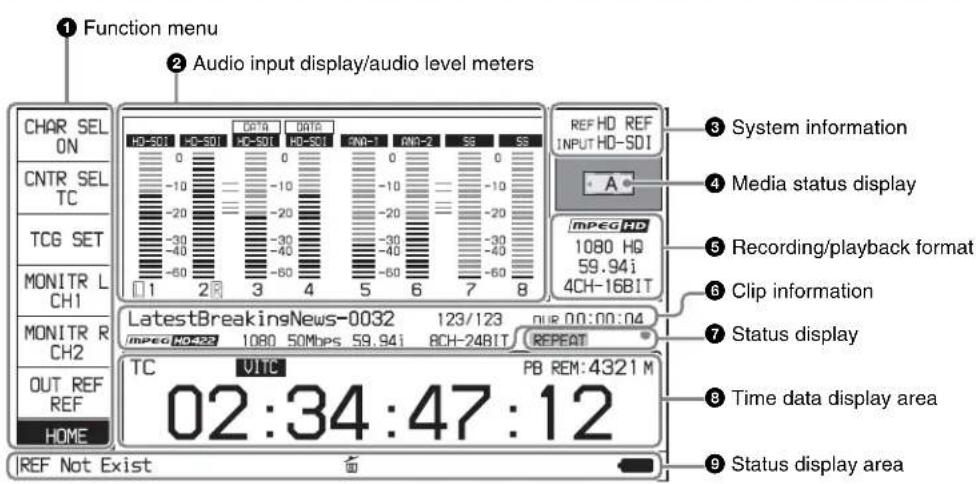
Use the PAGE/HOME button to display this menu, and to switch between the pages (HOME, P1 to P5, (P6) ^1) , (HOME2) ^1) ) of the menu. Each page has one to six setting items. Press the corresponding function button to change a setting.
1) When configured in maintenance menu item M38: F-KEY CONFIG
For details, see "Basic Operations of the Function Menu" (page 37).
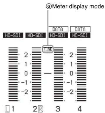
Displays information about audio. There are two display modes for the audio level meter: FULL mode and FINE
mode, which can be switched using AU METER on page P3 AUDIO of the function menu.
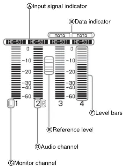
Meter display mode: FINEMeter display mode: FULL
Ⓐ Input signal display: Displays the audio input signal.
| Display Input signal |
| ANA-1 Analog audio signal Channel 2, 4, 6, 8 | nel 1, 3, 5, 7 |
| ANA-2 Channel 2, 4, 6, 8 | |
| HD-SDI HDSDI audio signal (flashes when there is no input signal) |
| SD-SDI SDSDI audio signal (flashes when there is no input signal) |
| SG Test signal from the internal signal generator |
⑧Data indication: Appears when the input signals are non-audio signals.
©Monitor channel: Displays the audio monitoring channels set with MONITR L and MONITR R on the HOME page of the function menu (see page 37).
⑭Audio channel: Displays the audio channels. Also indicates preset or variable-speed mode by its color (see page 11).
White: Preset mode
Green: Variable-speed mode
⑤ Reference level: Displays the reference level for recording as set in the maintenance menu.
For details about the reference level setting, refer to the maintenance menu item M37 (page 95).
⑤ Level bars: Display the audio recording or playback levels of channels 1 to 8. The OVER indicators light when the audio level exceeds 0 dB.
⑥ Meter display mode: Displays the audio level meter display mode selected with AU METER on page P3 AUDIO of the function menu (see page 38).
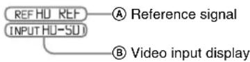
Ⓐ Reference signal: This displays the type of reference signal to which this unit is synchronizing.
When there is no display, the unit is synchronizing to the internal reference signal.
INPUT: Input video
HD REF: HD-format reference signal
SD REF: SD-format reference signal
⑧ Video input display: This displays the selected video input signal.
HD-SDI: HDSDI video input
SD-SDI: SDSDI video input
SG: Test video signal from the internal signal generator
The video signal input is selected with V INPUT on page P1 INPUT of the function menu (see page 38).
Note
The display blinks when there is no video input signal, and when the video input signal does not match the system frequency of this unit.
Displays the icons in the following table to indicate the status of the selected recording media.
| Icons Status | |
| SxS memory card (slot A selected) | External storage |
| No Media | No Media | Not loaded |
| — Being mounted |
| A | | Normal status |
| A | | Warning level error has occurred. |
| A× | | Error has occurred. (Restoring is impossible.) |
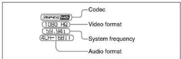
This displays the recording format during recording and the playback clip format during playback.
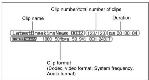
Displays clip information.
⑦Status display
Displays icons indicating the status of this unit.
| Icon Description |
| REPEAT | Currently set to the repeat playback mode |
| SINGLE | Currently set to the single clip playback mode |
| SNGL RPT | Currently set to the single clip playback mode with the repeat playback mode |
| FC | 1080/720 cross-convert output |
| ● | Recording |
⑧ Time data display area
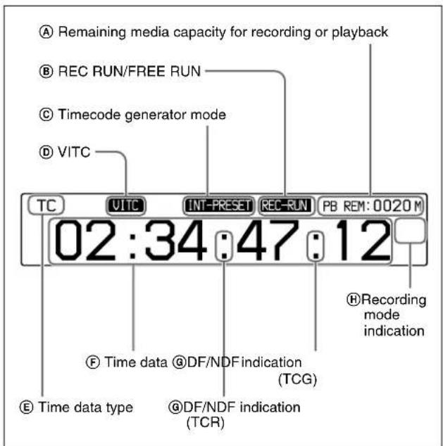
④Remaining media capacity for recording or playback: Displays the remaining recording/playback capacity of the recording media. It flashes when the remaining recording capacity of the selected memory card is less than one minute.
In relay recording mode, it displays the remaining recording capacity of slots A and B. It flashes when the remaining recording capacity of slots A and B is less than four minutes.
⑧REC RUN/FREE RUN: Displays the timecode run mode. The run mode is set with RUN MODE on page P4 TC of the function menu (see page 39).
©Timecode generator mode: Displays the timecode source and generation method (preset or regenerate). These are set with TCG and PRST/RGN on page P4 TC of the function menu (see page 39).
©VITC: Lights in the following cases.
- When VITC is read in playback mode. (This has no relations to the display in the time data display area.)
- When VITC recording is possible.
⑤Time data type: Displays the type of time data displayed in the time data display area. The type of time data is selected with CNTR SEL on the HOME page of the function menu (see page 37).
| Display Type | of time data |
| TC Timecode | |
| COUNTER Elapsed recording/playback time |
| UB User bits | |
| VITC VITC | |
| VIUB VIUB | |
| TCG Timecode generator value |
| UBG User bits generator value |
⑤Time data: Normally displays timecode or VITC, according to the selection made with TCR on page P4 TC of the function menu.
In Pre-read edit mode, the display is presented on 2 rows, with “PREREAD” appearing in the bottom row.
©DF/NDF indication: Displays the frame count mode for the internal timecode reader (TCR) and internal timecode generator (TCG). The frame count mode is set with DF/NDF on page P4 TC of the function menu (see page 39).
| Display Frame count mode |
| . DF (drop-frame mode) |
| : NDF (non-drop-frame mode) |
⑧Recording mode indication: Displays an icon when recording in relay recording mode.
| Icon | Recording mode |
| – Normal recording mode |
| A←□B→ | Relay recording mode |
⑨Status display area
flowchart
graph TD
    A["Error, warning, and alarm messages"] --> B["REF Not Exist"]
    B --> C["Delete icon"]
    C --> D["NETWORK"]
    D --> E["NET-RMT"]
    E --> F["BANK1"]
    F --> G["Power source display"]
    G --> H["Menu setting status"]
    H --> I["Network remote connection display"]
    I --> J["Network connection display"]
    J --> K["Copy icon"]
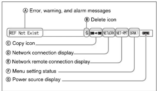
ⒶError, warning, and alarm messages: Messages about operations and the status of the unit appear here. The seriousness of the message is indicated by the color, as follows.
Red: Error message (flashing)
Orange: Warning message
White: Alarm message
⑧ Delete icon: Flashes while a clip deletion is being executed.
© Copy icon: During a clip copy operation, displays an icon indicating the copy source/copy destination media.
| Icon | Copy source/copy destination media |
 | SxS memory card/SxS memory card |
 | External storage/SxS memory card |
 | SxS memory card/external storage |
⑭ Network connection display: Lights while data is being exchanged with a network connected external device.
⑧Network remote connection display: “NET-RMT” or “RM-SDI” is displayed during a network remote control connection to an external device (see page 47).
⑤ Menu setting status: Displays the current setup menu settings.
| Display | Current setup menu settings |
| BANK1 | Same as those in menu bank 1. |
| BANK2 | Same as those in menu bank 2. |
| BANK3 | Same as those in menu bank 3. |
| DEFAULT | Same as the factory default settings. |
| Nothing displayed | Different from any of the above. |
⑥Power source display: Displays the icon for the power source being used
| Icon | Power source being used |
| AC power source |
| Battery |
When the remaining battery power drops below a certain level, the icon for battery starts flashing (this is the battery near end alarm).
Note
With the battery near end alarm displayed, when the battery voltage drops below the shutdown voltage set with setup menu item 033 BATTERY END VOLTAGE, the unit is automatically shut down.
Video monitor screen

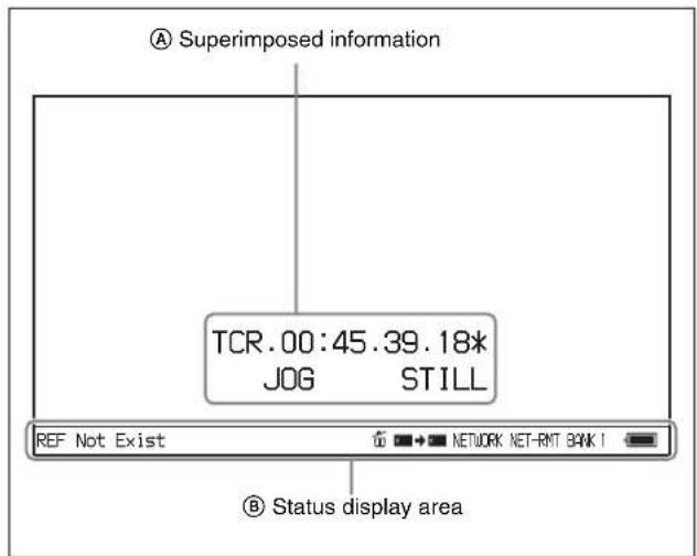
ⒶSuperimposed information: Appears when CHAR SEL on the HOME page of the function menu is set to "ON".
⑧Status display area: Displays messages and icons about the status of the unit (see page 17).
You can disable the status display area with the DISPLAY button. However, it is automatically enabled when:
- Display of error/warning/alarm message becomes necessary.
- During battery-driven operation, the power source display starts flashing (the battery near end alarm is given).
Rear Panel
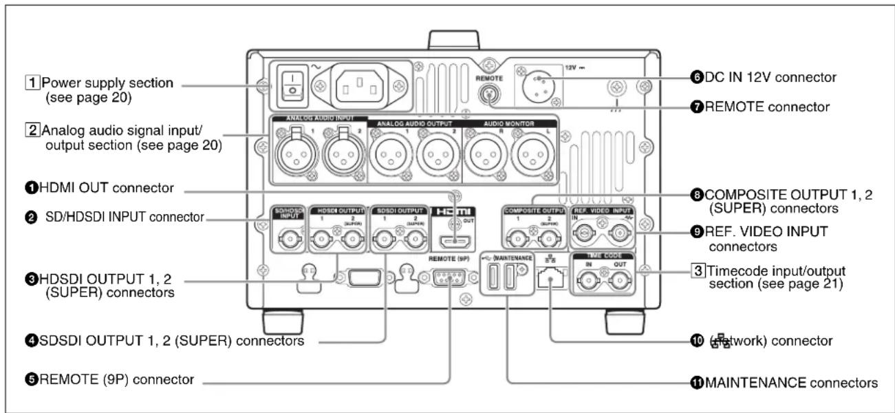
①HDMI OUT connector
Connects to an HD projector, HD television, or other HD consumer device, and outputs digital signals (video, audio, and control signals).
The audio signals of the channels selected with MONITR L and MONITR R on the HOME page of the function menu are output.
You can superimpose timecodes, menu settings, and error messages on the HDMI output using the CHAR SEL setting on the HOME page of the function menu.
See “Basic Operations of the Function Menu” (page 37) for more information about the MONITR L and MONITR R settings.
This inputs an SDSDI or HDSDI format video/audio signal.
③HDSDI OUTPUT 1, 2 (SUPER) (HDSDI signal output 1, 2 (superimpose)) connectors (BNC type)
These output HDSDI format video/audio signals.
You can superimpose timecodes or other information on the output of the HDSDI OUTPUT 2 (SUPER) connector using the CHAR SEL setting on the HOME page of the function menu or with the setting for setup menu item 028 HD CHARACTER. You can always disable to superimpose the data independent of the setting for CHAR SEL with the setting for setup menu item 028.
See “Basic Operations of the Function Menu” (page 37) for more information about the CHAR SEL settings.
See page 79 for more information about the setup menu item 028 HD CHARACTER.
To treat the input and output signals of these connectors as non-audio signals, set a maintenance menu item.
For details, refer to maintenance menu item M37 (page 95).
④ SDSDI OUTPUT 1, 2 (SUPER) (SDI signal outputs 1, 2 (superimpose)) connectors (BNC type)
These output SDSDI format video/audio signals.
When the unit is shipped from the factory, audio signal output is eight channels with no switching, and RP188 timecode output is set to on. You can change these settings with setup menu item 828 SDI AUDIO OUTPUT SELECT and setup menu item 920 SD-SDI H-ANC CONTROL.
The output from the 2 (SUPER) connector can have timecode and other text information superimposed. To turn superimposition off, set CHAR SEL on the HOME page of the function menu to "OFF".
See “Items in the extended menu” (page 83) for more information.
See “Basic Operations of the Function Menu” (page 37) for more information.
⑤ REMOTE (9P) (remote control 9-pin) connector (D-sub 9-pin)
Connect a controller that supports the VDCP protocol or the RS-422A Sony 9-pin VTR control protocol.
⑥DC IN 12V connector (XLR 4-pin, male)
Connect to a DC power source of 12 V.
When using the BKP-L551 Battery Adaptor to mount a battery pack, connect the power cable of the BKP-L551.
For details, see "Supplying power" on page 22.
⑦ REMOTE connector (4-pin)
Supplies power to the RM-280 Remote Edit Controller.
⑧ COMPOSITE OUTPUT 1, 2 (SUPER) (analog composite video output 1, 2 (superimpose)) connectors (BNC type)
Output analog composite video signals. You can superimpose timecodes on the output of the 2 (SUPER) connector when CHAR SEL on the HOME page of the function menu is set to ON.
See “Basic Operations of the Function Menu” on page 37 for more information about the CHAR SEL setting.
⑨REF. VIDEO INPUT (reference video signal input) connectors (BNC type)
The two connectors form a loop-through connection; when a reference video signal is input to the left connector, the same signal is input from the right connector ( W ) to a connected device. When no connection is made to the right connector, the left connector is automatically terminated with an impedance of 75 ohms.
⑩ (network) connector (RJ-45 type)
This is a 10BASE-T/100BASE-TX/1000BASE-T connector for network connection.
CAUTION
- For safety, do not connect the connector for peripheral device wiring that might have excessive voltage to this port. Follow the instructions for this port.
- When you connect the LAN cable of the unit to peripheral device, use a shielded-type cable to prevent malfunction due to radiation noise.
⑪ MAINTENANCE connectors
These are the High Speed USB (USB2.0) connectors for maintenance.
1 Power supply section
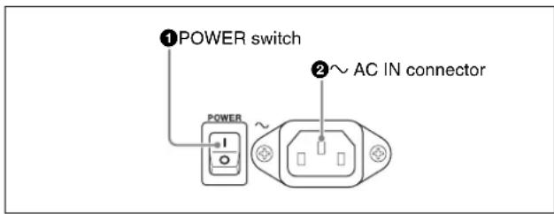
①POWER (main power) switch
Press the I side to power on the unit. Press the O side to power off.
When using the unit, normally leave the POWER switch in the I (on) position, and use the on/standby button on the front panel to switch the unit between the operating state and standby state.
Note
Before turning the main power off, always check to be sure that the unit is in the standby state, and then press the main power switch to the ○ side.
②\~AC IN connector
Connect to an AC power source with the power cord (not supplied).
2 Analog audio signal input/output section
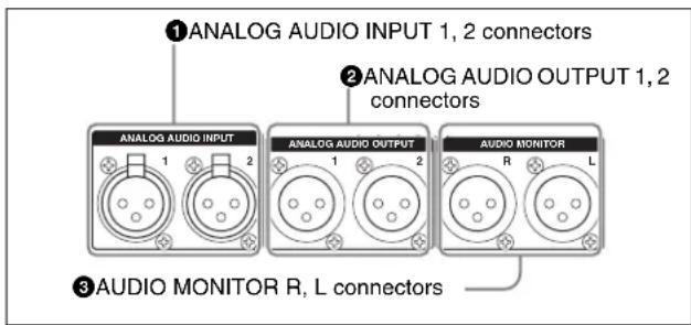
①ANALOG AUDIO INPUT 1, 2 connectors (XLR 3-pin, female)
These input analog audio signals.
With A1 INPUT, A2 INPUT, A3 INPUT or A4 INPUT on page P1 INPUT of the function menu (see page 38), you can select whether the signal input to connector 1 is assigned to audio channel 1 or 3, and whether the signal input to connector 2 is assigned to audio channel 2 or 4. You can set the reference input level with the maintenance menu. (Factory default setting: +4dB)
For details, refer to the Service Manual.
②ANALOG AUDIO OUTPUT 1, 2 connectors (XLR 3-pin, male)
These output analog audio signals.
When the unit is shipped from the factory, the 1 connector is set to audio channel 1, and the 2 connector is set to audio channel 2. You can change these settings with setup menu item 824 ANALOG LINE OUTPUT SELECT (see page 90).
You can set the output level with the maintenance menu.
(Factory default setting: +4dB)
Non-audio signals are muted.
For details, refer to maintenance menu item M37 (page 95).
③ AUDIO MONITOR R, L connectors (XLR 3-pin, male)
This outputs an audio signal for monitoring.
The monitored channel is selected with MONITR L and MONITR R on the HOME page of the function menu.
See “Basic Operations of the Function Menu” (page 37) for more information about the MONITR L and MONITR R settings.
①TIME CODE IN connector

①TIME CODE IN connector (BNC type)
This inputs an SMPTE timecode generated by an external device.
②TIME CODE OUT connector (BNC type)
This outputs the following timecode, depending on the operating state of this unit.
During playback: Playback timecode
During recording: The timecode from the internal
timecode generator or the timecode input to the TIME
CODE IN connector
Preparations
Chapter
3
Preparing Power Sources
This unit can be powered by AC power, DC power, or a battery pack.
For safety, use only the Sony battery packs listed below.
Lithium-ion battery pack: BP-GL95B
Note
If you load or remove a battery pack incorrectly, it may fall and cause bodily injury. Follow the procedures described below to load or remove them.
Supplying power
AC power supply
Connect the AC IN connector to an AC power source using the specified AC power cord. To supply AC power to the unit, press the on/standby button (☐) on the front panel and hold it down for a short time (0.25 seconds or longer). and the POWER switch on the rear panel to I (on).
DC power supply
Connect the DC IN 12V connector to a DC power source. To supply DC power to the unit, press the on/standby button (☐) on the front panel and hold it down for a short time (0.25 seconds or longer), and turn off the POWER switch on the rear panel. If the POWER switch on the rear panel is set to I (on), AC power is supplied.
Battery power supply
You can use the BP-GL95B Battery Pack with this unit. To use battery pack, a BKP-L551 Battery Adaptor and a BC-L100 Battery Charger are also required.
Continuous recording time at room temperature
BP-GL95B lithium-ion battery pack: Approx. 85 minutes
For details on charging battery packs, refer to the operation manual for the battery charger.
Notes about battery usage
- As long as a battery is connected to the unit, electric current flows in the unit to keep the CPU in the standby state even when the unit is not powered.
- Before using the batteries, be sure to charge them fully with the special battery charger. Refer to the operating instructions for your battery charger for more information about how to charge the batteries.
- Batteries may not be completely charged if you charge them immediately after use when they are still warm. You should wait until the batteries cool before charging them.
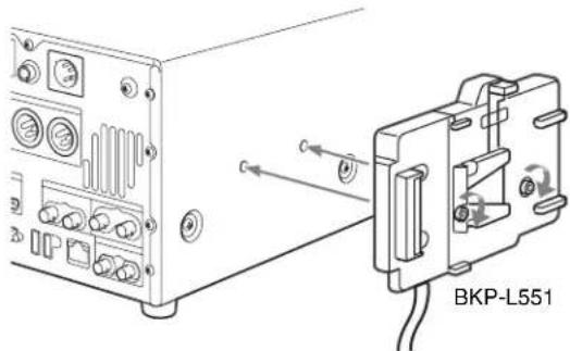
Attaching a battery pack
Use the BKP-L551 in the following way to attach and remove the BP-GL95B Battery Pack.
For details on attaching the BKP-L551, refer to the installation manual for the BKP-L551.
WARNING
Batteries shall not be exposed to excessive heat such as sunshine, fire or the like.
CAUTION
Danger of explosion if battery is incorrectly replaced.
Replace only with the same or equivalent type recommended by the manufacturer.
When you dispose of the battery, you must obey the law in the relative area or country.
1 Attach the BKP-L551 to the side panel.
2 Align the grooves on the BP-GL95B with the projections on the BKP-L551.
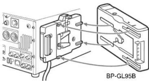
3 Slide the BP-GL95B as shown below so that the connectors on the BP-GL95B and the BKP-L551 are connected.
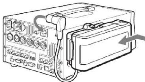
natural_image
Line drawing of an electronic device with ports and cables, no text or symbols present
4 Connect the DC cable of the BKP-L551 to the DC IN 12V connector.
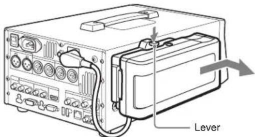
Removing the battery pack
With the lever pushed in, slide the BP-GL95B out as shown below.
Checking the remaining battery power
You can use the LEDs on the side panel of the battery to check the remaining power of the battery.
When the remaining battery power decreases substantially and the voltage approaches the set shutdown voltage, the power source icon starts flashing in the status display area of the display screen (the battery near end alarm is given).


Initial Setup
This unit is shipped with the password, area of use, system frequency, and current date and time still unset.
Therefore, you need to make initial setup settings before using the unit. (You cannot use the unit without setting it up.)
Once the unit has been set up, the settings are retained even when the unit is powered off.
Use the following procedures.
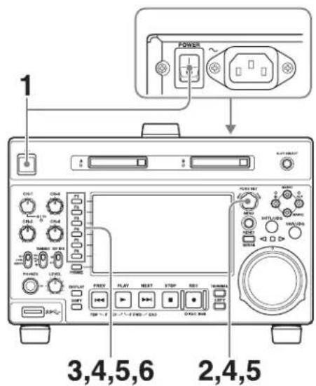
1 Power the unit on.
The PASSWORD SETUP screen appears on the display.
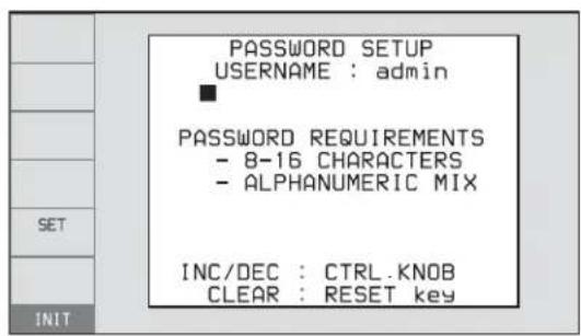
■: Flashing cursor
2 Set the password.
To enter a character, turn the PUSH SET knob to select a character, and then push the PUSH SET knob. Press and hold the SHIFT button and turn the PUSH SET knob to switch the character type in the order
Numbers → Upper-case letters → Lower-case letters → Symbols.
To delete a character, press the RESET button. Press and hold the SHIFT button and press the RESET button to delete all characters.
Entered characters are displayed as asterisks after a short delay. To view the entered characters, press the DISPLAY button. The characters are displayed while the button is pressed.
The valid characters for passwords are numbers, upper/lower-case alphabetic characters and symbols ((space) ! " # \$ % & ' ( ) * + , - . / : ; <= > ? @ [ \ ] ^ _ { | } \~).
3 After setting the password, press the SET function button (F5).
A confirmation screen appears if the password security strength is deemed to be weak.
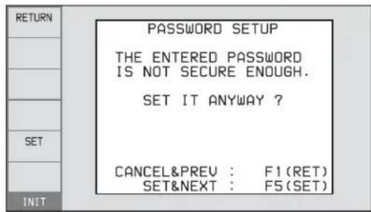
To reset the password
Press the RETURN function button (F1).
To continue without changing the password Press the SET function button (F5).
The INITIAL SETUP screen appears on the display.
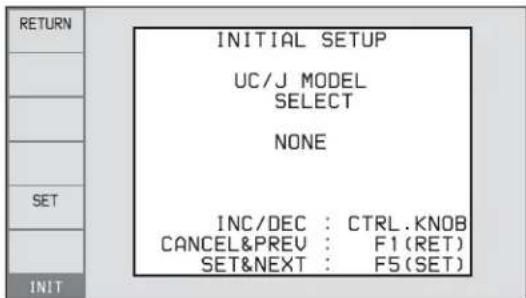
4 Turn the PUSH SET knob to select the area of use.
Display UC (for regions outside Japan) or J (for Japan), and then press the SET function button (F5). The system frequency screen appears.
5 Turn the PUSH SET knob to select the system frequency.
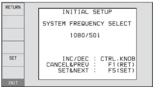
Display the system frequency that you want to use, and then press the SET function button (F5).
The recording format selection screen appears.
6 If you want to save the settings made up to this point, press the SET function button (F5) again.
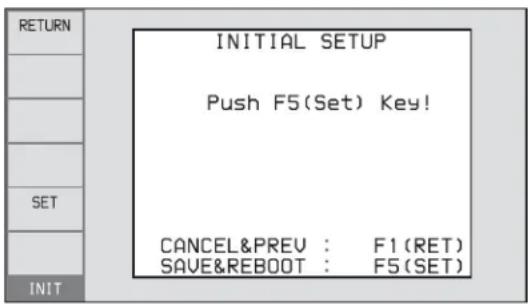
The message “NOW SAVING...” appears again, and the setting screen disappears. Then the unit powers itself off and on again.
To return to the original screen without saving settings
Press the RETURN function button (F1).
To set the date and time
Set a maintenance menu item.
For details, refer to maintenance menu item M3D (page 96).
Connections and Settings
Note
Production of some of the peripherals and related devices described in this chapter has been discontinued. For advice about choosing devices, please contact your Sony dealer or a Sony representative.
Connections for Content Browser and non-Sony nonlinear editors
When using Content Browser, you can have a remote access to this unit from a network connected computer. You can also access to this unit from a nonlinear editor that is not a Sony product via FTP/CIFS, and use this unit as a material server.
For an overview and installation of Content Browser, access the Sony website closest to your area.
Using the _e (network) connector (FTP connection)
The following shows an example of an FTP (File Transfer Protocol) connection.
Note
The PMW-1000 IP address and other network-related settings are required for connection.
For details of the network-related settings, refer to the maintenance menu M5 (page 97).
Connecting this unit directly to a laptop computer
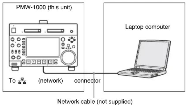
Settings on this unit
Remote control switch: NET (see page 11)
Setup menu item 257 NETWORK ENABLE: net
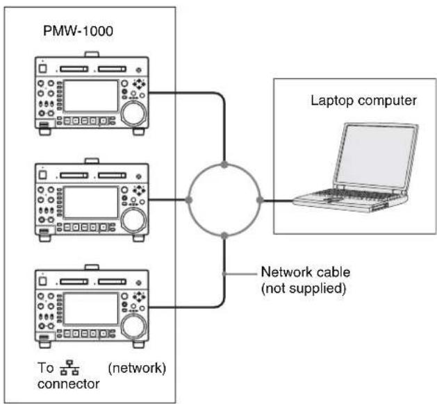
Connecting three PMW-1000 units to a laptop computer via a LAN
flowchart
graph TD
    A["PMW-1000"] --> B((Network Cable)]
    C["Laptop computer"] --> B
    D["To (network) connector"] --> B
    B --> E["Network cable (not supplied)"]
CAUTION
When you connect the Network cable of the unit to peripheral device, use a shielded-type cable to prevent malfunction due to radiation noise.
| Settings on all PMW-1000 |
| Remote control switch: NET (see page 11) |
| Setup menu item 257 NETWORK ENABLE: net |
Connections for cut editing
The following figure shows a cut editing system comprising this unit as a player.
When making the connections, also refer to the manuals provided with the equipment to be connected.
See page 28 for more information about editing control unit settings.
When using an editing control unit
Using BVE-700/700A
The following figure shows a cut editing system comprising this unit as a player, an HDW-M2000/M2000P unit as a recorder, and a BVE-700/700A as an editing control unit.
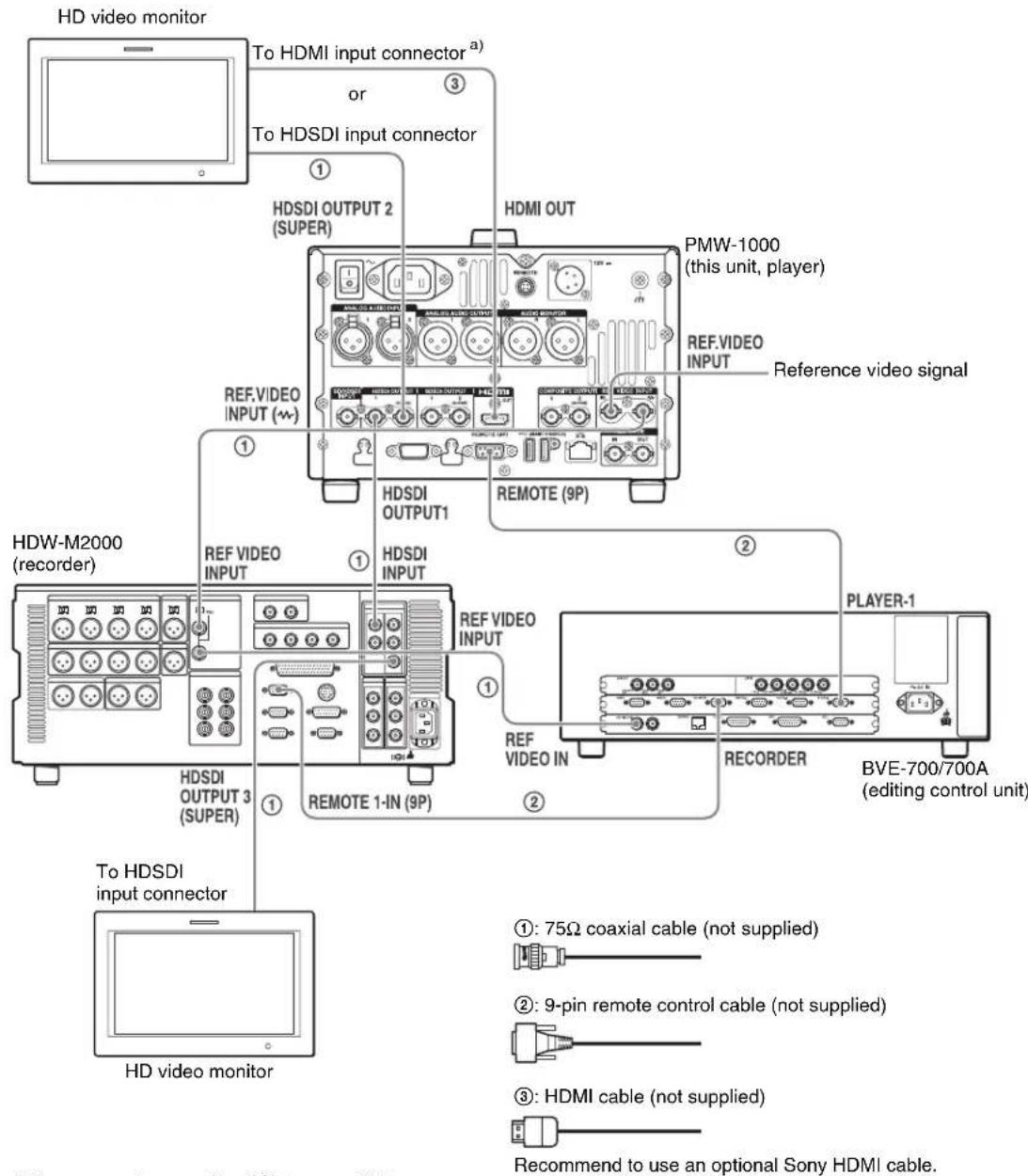
a) You can use setup menu item 161 (see page 84) to set which signal to output from the HDMI OUT connector: the same signal as the HDSDI OUTPUT 2 (SUPER) connector output, or the HDSDI signal and thumbnails view signal by automatically switching between them.

| HDW-M2000 (recorder) settings | BVE-700/700A (editing control unit) setting | Settings on this unit |
| REMOTE 1 (9P) button: Lit SYNCHRONIZE menu:OFF Remote control switch: | | REMOTE (see page 11) |
| REF.VIDEO INPUT connector 75 Ω termination switch: OFF | Setup menu item 214REMOTE INTERFACE:9PIN |
| Audio selection function switching buttonINPUT button: HDSDI |
| Function menu HOME >F1 (VID. IN): SDI |
| Function menu page 1 >F1 (TCG): INT |
| Function menu page 1 >F2 (PR/RGN): PRESET |
| Function menu page 1 >F3 (RUN): FREE |
Editing Control Unit Settings
When connecting an editing control unit (BVE-700/700A/
2000) to use with this unit, set VTR constants as follows.
| System frequency VTR constant |
| 1 2 3 | 4 5 6 | 7 8 9 | 10 11 | 12 13 | 14 15 | 16 | | | | | | | | | |
| 59.94i/59.94P/29.97P | A0 | B3 | 00 | 96 | 07 | 07 | 03 | 80 | 0A | 07 | FE | 00 | 80 | 5A | FF | 5A |
| 50i/50P/25P | A1 | B3 | 00 | 7D | 07 | 07 | 03 | 80 | 0A | 07 | FE | 00 | 80 | 4C | FF | 4B |
| 23.98P | A2 | B3 | 00 | 78 | 07 | 07 | 03 | 80 | 0A | 07 | FE | 00 | 80 | 48 | FF | 48 |
Using RM-280
The following figure shows a cut editing system comprising a PMW-1000 as a player, a PDW-F1600 unit as a recorder, and an RM-280 as an editing controller.
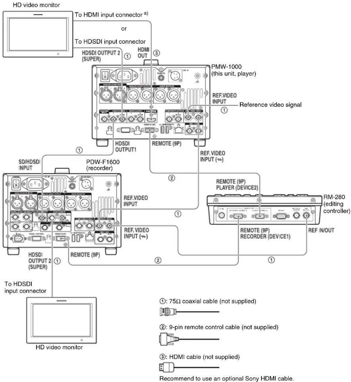
a) You can use setup menu item 161 (see page 84) to set which signal to output from the HDMI OUT connector: the same signal as the HDSDI OUTPUT 2 (SUPER) connector output, or the HDSDI signal and thumbnails view signal by automatically switching between them.

| PDW-F1600 (recorder) settings | RM-280 (editing controller) settings | PMW-1000 (player) settings |
| Remote control switch: REMOTE EDITOR/REMO | TE CONTROL selectorswitch: EDITOR | Remote control switch:REMOTE (see page 11) |
| Setup menu item 214 REMOTE INTERFACE:9PIN | Setup menu 01 PREROLL: 5s Setup menu item | m 214REMOTE INTERFACE: 9PIN |
| Function menu page P1 VIDEO >V INPUT: HDSDI | Setup menu 05 SYNC SEL: ON |
| Function menu pages P2 and P3 AUDIO >A1 toA8 INPUT: SDI | Setup menu 06 SYNC VTR: RECORDER |
| Function menu page P4 TC >TCG: INT Setup menu 09 EDIT DLY: -7 |
| Function menu page P4 TC >PRST/RGN:PRESET | Setup menu 10 R ST DLY: AUTO |
| Function menu page P4 TC >RUN MODE:FREE RUN | Setup menu 11 P ST DLY: AUTO |
Using the editing functions of the recorder (controlling through REMOTE(9P) connector)
The following figure shows a cut editing system comprising this unit as a player, and an HDW-M2000/M2000P unit as a recorder. In this example, video and
audio signals are connected by HDSDI, and control signals are transferred via the REMOTE(9P) connector.
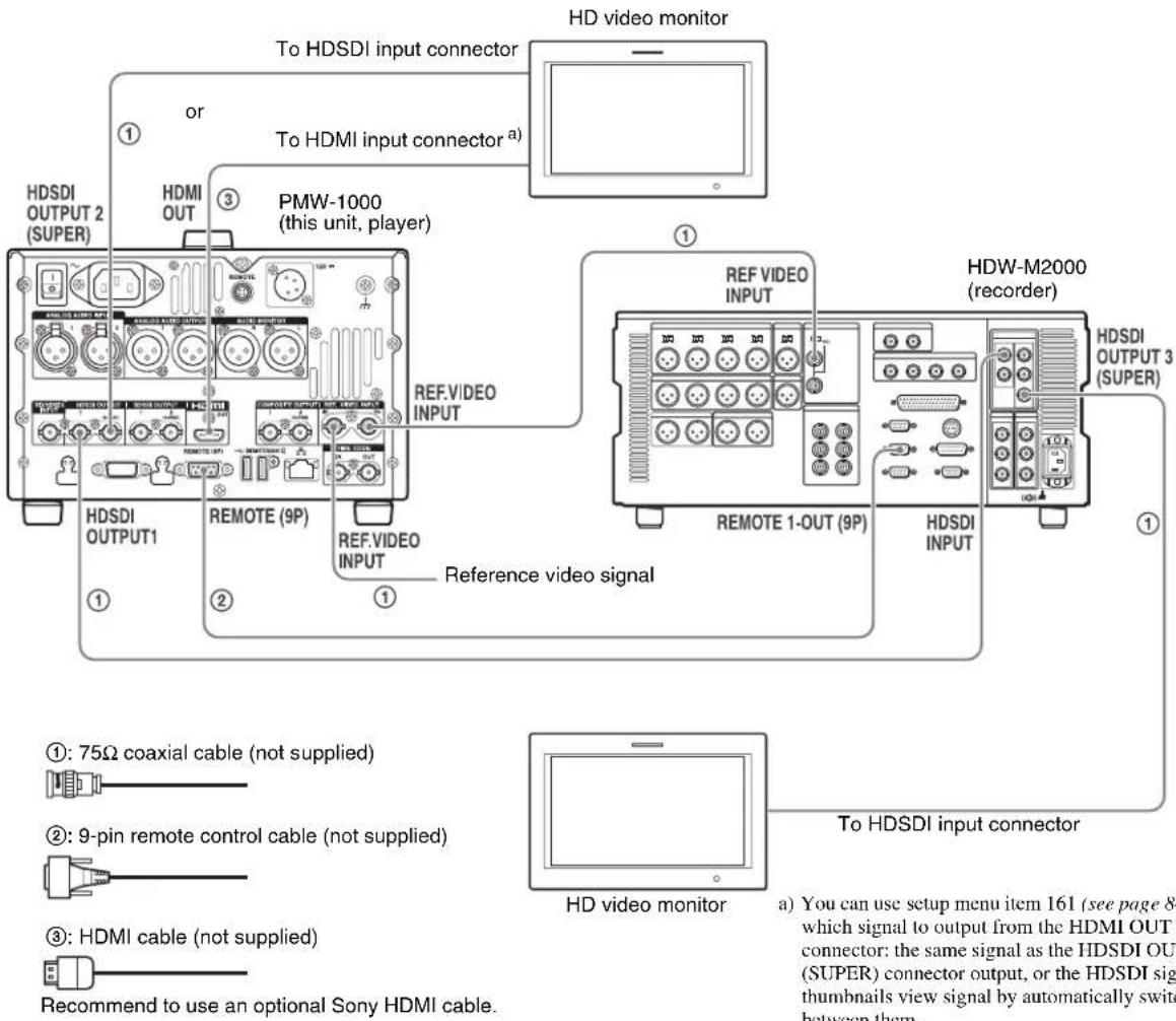
| HDW-M2000 (recorder) setting | Settings on this unit |
| REMOTE 1 (9P) button: Unlit | Remote control switch: REMOTE (see page 11) |
| Setup menu item 214 REMOTE INTERFACE: 9PIN |
For details of HDW-M2000/M2000P settings, refer to the HDW-M2000/M2000P Operation Manual.
Connections for pool coverage
The following figure shows an example of connections for pool coverage, with the PDW-700 Professional Disc Camcorder connected.
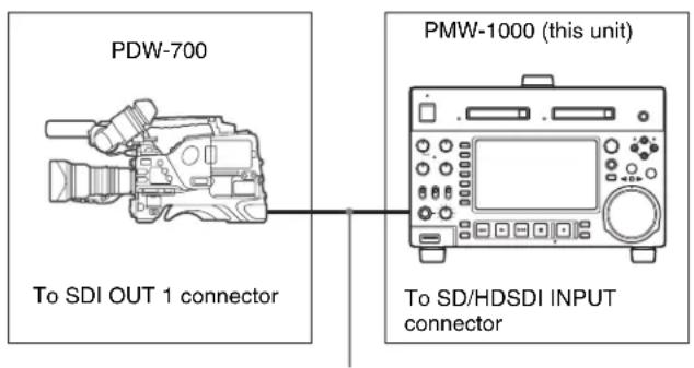
75Ω coaxial cable (not supplied)
| PDW-700 (camcorder) setting | Settings on this unit |
| HDSDI REMOTE I/F on page CAM CONFIG 1 of the MAINTENANCE menu: other than OFF | Remote control switch: REMOTE (see page 11) |
| Setup menu item 214 REMOTE INTERFACE: SDI |

Synchronization Reference Signals
The synchronization reference signal generator of this unit synchronizes to a reference signal input to the REF. VIDEO INPUT connector or to a video input signal. External synchronization is as follows, depending on the
setting of OUT REF on the HOME page of the function menu, and on the type of the selected input signal. Video output signals are always synchronized to the internal synchronization signal.
| Input to SD/HDSDI INPUT connector^a) | Input to REF. VIDEO INPUT connector | Setting of OUT REF on the HOME page^b) |
| REF INPUT | |
| Yes Yes Synchronize to | the signal input to | the REF. VIDEO INPUT connector | Synchronize to the signal input to the SD/HDSDI INPUT connector |
| Yes No Synchronize to | the signal input to the SD/HDSDI INPUT connector |
| No Yes Synchronize to | the signal input to the REF. VIDEO INPUT connector |
| No No No external synchronization is made | |
a) Same as when INT SG on page P1 INPUT of the function menu is set to "ON".
b) FTP connection always synchronizes to the internal synchronization reference signal, regardless of the setting of OUT REF.
Synchronization reference signals when you are recording, playing, or editing 720P signals
When you are recording, playing, or editing 720P signals, set OUT REF on the HOME page of the function menu to "REF", and synchronize the synchronization reference signal generator of this unit to a reference signal input to the REF. VIDEO INPUT connector. The following reference signals can be used.
720/59.94P system: 1080/59.94i tri-level sync signal, 525 black burst signal
720/50P system: 1080/50i tri-level sync signal, 625 black burst signal
When you directly interconnect video I/O connectors between two of this unit or between this unit and the XDS-1000 or PDW-F1600/HD1500/F800/700, you can record and dub 720P signals even if you set OUT REF on the HOME page of the function menu to "INPUT".
Setting System Frequency
This unit can record and play back video at the system frequencies of 1080/59.94i, 50i, 29.97P, 25P, 23.98P or 720/59.94P, 50P.
Selecting the system frequency
1 Set setup menu item 013 SYSTEM FREQUENCY SELECT MENU to "on" and press the PUSH SET knob.
A confirmation message appears asking you whether to change the system frequency.
2 To change the system frequency, select "on", and then press the PUSH SET knob.
To cancel changing the system frequency Select "off", and then press the PUSH SET knob.
The system frequency selection screen appears.
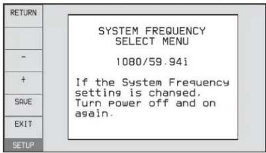
3 Turn the PUSH SET knob to select the system frequency to be used.
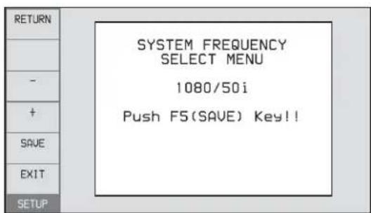
4 Press the PUSH SET knob or the SAVE function button (F5).
The message "Turn off/on POWER!!" appears.
5 After pressing the on/standby button and hold it down for one second or longer to the unit into the standby state, power it on again.
Setting Timecode
There are the following four ways of recording timecode:
Internal Preset mode: This records the output of the internal timecode generator, set beforehand to an initial value. The following run modes can be selected.
• Free Run: Timecode always advances continuously as long as the unit is powered on.
- Rec Run: Timecode advances only during recording.
Internal Regen (regenerate) mode: This records the output of the internal timecode generator, initialized to timecode following continuously upon the timecode of the last frame of the last clip on the SxS memory card.
External Regen mode: This records the output of the internal timecode generator, synchronized to an external timecode generator. As the external input, the timecode input to any of the following connectors can be selected.
• TIME CODE IN connector: LTC
• SD/HDSDI INPUT connector: VITC and LTC
External Preset mode: This directly records the input of an external timecode generator. As the external input, the timecode input to any of the TIME CODE IN connector can be selected.
To record timecode after setting an initial value (Internal Preset)
Proceed as follows with the function menu. For setting the timecode, set TCG on page P4 TC of the function menu to "INT" and PRST/RGN to "PRESET".
Setting an initial timecode value
1 Press the CNTR SEL function button (F2) on the HOME page of the function menu, and select TC.

2 Press the TCG SET function button (F3).
The first digit of the time data display starts flashing.
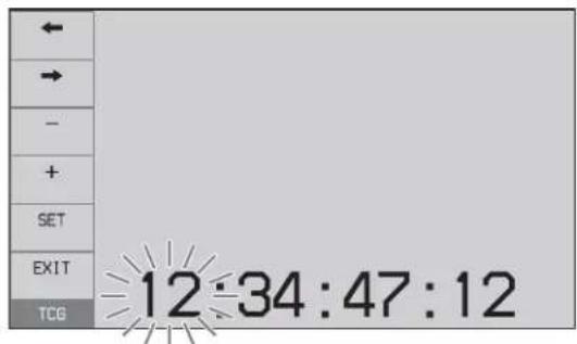
3 Press the ← or → function button (F1 or F2) to select a digit to be set.
The selected digit starts flashing.
4 Use the PUSH SET knob or - or + function button (F3 or F4) to set the value for the selected digit.
To set the next-most significant digit (10s place)
Turn the PUSH SET knob while holding down the SHIFT button.
Repeat steps 3 and 4 to set all digits that should be set.
To set to 00:00:00:00
Press the RESET/RETURN button.
5 Press the SET function button (F5).
If RUN MODE on page P4 TC is set to "FREE RUN", the timecode starts running.
To cancel a setting
Press the EXIT function button (F6). Any new settings to that point are canceled, and the setting operation is terminated.
Setting the timecode to the current time
1 Set RUN MODE on page P4 TC to "FREE RUN" and DF/NDF to "DF" (in 59.94i/59.94P/29.97P mode only).
2 Perform steps 1 to 4 of "Setting an initial timecode value" to set the timecode to a time slightly ahead of the current time.
3 Press the SET function button (F5) at the instant when the current time matches the displayed timecode.
Setting user bits
You can record up to 8 hexadecimal digits of information (date, time, event number, etc.) on the timecode track. Select UB by pressing the CNTR SEL function button (F2) in step 1 of "Setting an initial timecode value" and carry out steps 2 to 5. Settings are made in hexadecimal (0-9, A-F).
You can record ID codes in user bits.
To record timecode that follows sequentially upon the last recorded timecode (Internal Regen)
You can record timecode so that it is continuous from one clip to the next on the SxS memory card.
Set TCG on page P4 TC of the function menu to INT, and PRST/RGN to TC or VITC. When this setting is in force, the unit reads the timecode of the last frame of the last recorded clip on the SxS memory card before starting to record, and internally generates timecode that follows upon the recorded timecode.
The frame count mode (for system frequency 59.94i/59.94P/29.97P only) is set to the same mode as the last recorded timecode on the SxS memory card (drop-frame or non-drop-frame).
To record with the internal timecode generator synchronized to external timecode (External Regen)
Use this method to synchronize the timecode generators of a number of recorders, to record the playback timecode of external VTRs, or to record while maintaining synchronization between the source video and timecode. Use either of the following procedures according to the type of external timecode.
1 Connect the timecode output of an external device to the TIME CODE IN connector, and input a reference video signal to the REF. VIDEO INPUT connector.
2 Make the following settings on page P4 TC of the function menu.
- Set TCG to "EXT".
- Set PRST/RGN to "TC".
1 Input an SDI signal containing embedded LTC to the SD/HDSDI INPUT connector, and a reference video signal to the REF. VIDEO INPUT connector.
2 Make the following settings on page P4 TC of the function menu.
- Set TCG to "SDI".
- Set PRST/RGN to "TC".
Executing either of these procedures starts the internal timecode generator running in synchronization with the external timecode generator.
Once the internal timecode generator is synchronized with the external timecode generator, the internal timecode generator continues to run even if the external timecode generator connection is removed.
The timecode advance mode is set automatically to Free Run. The frame count mode (for system frequency 59.94i/59.94P/29.97P only) is set to the same mode as the external timecode signal (drop-frame or non-drop-frame).
To check the synchronization to the external signal
Press the STOP button to stop this unit, then press the REC button.
Check that the timecode value shown in the time data display coincides with the external timecode value.
To record external timecode directly (External Preset)
When you use this method, the internal timecode generator advances without being affected by the external timecode.
Input the timecode output of an external device to the TIME CODE IN connector, and make the following settings on page P4 TC of the function menu.
- Set TCG to "EXT".
- Set PRST/RGN to "PRESET".
Superimposed Text Information
The video signal output from the COMPOSITE OUTPUT 2 (SUPER) connector, SDSDI OUTPUT 2 (SUPER) connector, HDSDI OUTPUT 2 (SUPER) connector, and HDMI OUT connector contains superimposed text information, including the timecode.
Adjusting the text display
You can adjust the position, size and type of the superimposed text using setup menu items 002, 003, 005, 009, and 011.
For details, see "Items in the basic menu" (page 77).
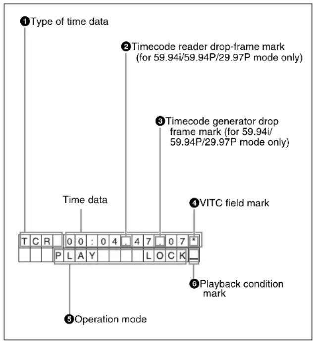
Information displayed
Note
The display shown above corresponds to the factory default settings of the unit. You can change the type of information to be displayed in the lower line of the display by changing the setting of setup menu item 005 DISPLAY INFORMATION SELECT.
For details, see "Items in the basic menu" (page 77).


①Type of time data
| Display Meaning |
| CNT | Counter data |
| TCR | TC reader | timecode |
| UBR TC reader user bits data |
| TCR. VITC reader timecode |
| UBR. VITC reader user bits data |
| TCG | TC generator | timecode |
| UBG TC generator user bits data |
Note
If the time data or user bits data cannot be read correctly, they will be displayed with an asterisk. For example, "T*R", "U*R", "T*R." or "U*R.".
② Timecode reader drop-frame mark (for 59.94i/59.94P/29.97P mode only)
“.”: Indicates drop-frame mode.
“: Indicates non-drop-frame mode.
③Timecode generator drop-frame mark (for 59.94i/59.94P/29.97P mode only)
“.”: Indicates drop-frame mode (factory default setting).
“: Indicates non-drop-frame mode.
④VITC field mark
“” (blank): Fields 1 and 3 (for 59.94i/59.94P/29.97P/23.98P mode) or fields 1, 3, 5 and 7 (for 50i/50P/25P mode)
“*”: Fields 2 and 4 (for 59.94i/59.94P/29.97P/23.98P mode) or fields 2, 4, 6 and 8 (for 50i/50P/25P mode)
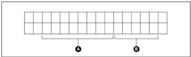
⑤Operation mode
The field is divided into two blocks as shown below.
- Block A displays the operation mode.
- Block B displays the servo lock status or playback speed.
| Display Operation mode |
| Block A Block B | |
| STOP Stop mode | |
| NEXT xxxx/xxxx Cuing up to the first frame of the next clip. |
| PREV xxxx/xxxx Cuing up to the first frame of the current clip. |
| F.FWD | Fast forward search |
| F.REV | Fast reverse search |
| Display Operation mode | |
| Block A Block B |
| PLAY | Playback mode (servo unlocked) |
| PLAY | LOCK | Playback mode (servo locked) |
| REC | Record mode (servo unlocked) |
| REC | LOCK | Record mode (servo locked) |
| JOG | STILL | A still picture in jog mode |
| JOG | FWD | Jog mode in forward direction |
| JOG | REV | Jog mode in reverse direction |
| SHUTTLE | STILL | A still picture in shuttle mode |
| SHUTTLE | (Speed) | Shuttle mode |
| VAR | STILL | A still picture in variable mode |
| VAR | (Speed) | Variable speed mode |
| TOP 0001/xxxx | Cuing up to the first frame of the first clip. |
| END xxxx/xxxx | Cuing up to the last frame of the last clip. |
| PREROLL | Cuing up during thumbnail search |
| COPY | Transcode copy is being executed. |
| CLOSE | A clip is not selected. |
| MEDIA OUT | No media is loaded. |
⑥Playback condition mark
Displays the playback condition using a mark during normal playback.
| Display | Name Description |
| A | Audio muting | Audio is muted when in playback mode (servo locked). Perform any required actions as described in the next section. |
| V | Video freeze | Video freezes when in playback mode (servo locked). Perform any required actions as described in the next section. |
If audio muting or video freeze occurs
If an audio muting or video freeze playback condition occurs, check the synchronization reference signal. If there is no problem with the synchronization reference signal, check the following items.
- If audio muting or video freeze occurs at the same location in a clip, the problem may have occurred during recording. Do not use the clip.
- If audio muting or video freeze occurs at different locations in a clip or with different clips, the problem may have occurred in the unit. If you should experience problems with the unit, contact your Sony service or sales representative.
The function menu provides access to frequently used settings, such as input video signal selection and timecode settings.
Menu settings are stored in nonvolatile memory and are preserved even after the unit is powered off.
The function menu appears on the color LCD of this unit. The following figure shows the buttons (F1 to F6 beginning at the top) used in function menu operations.
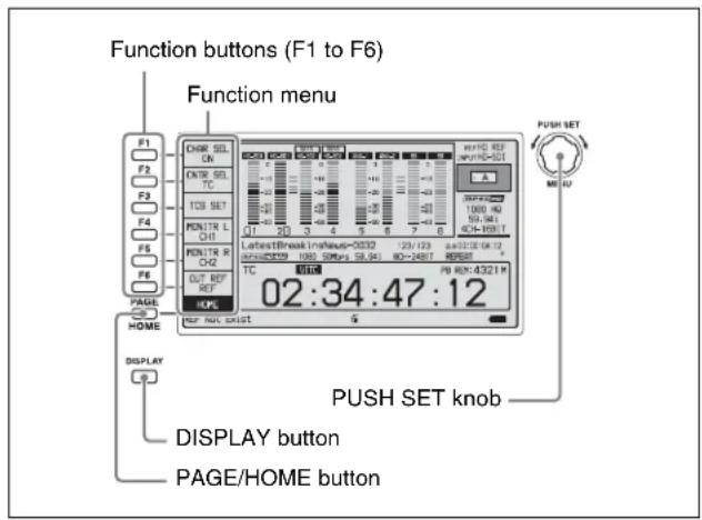
The function menu is made up of the HOME page and pages P1 to P5, (page P6) ^1) , (page HOME2) ^1) .
If the function menu is not already visible, press the PAGE/HOME button to display it. (The most recently accessed function menu page appears.)
To display a different page
Each press of the PAGE/HOME button displays the next function menu page in the order: HOME → P1 → P2 → P3 → P4 → P5 → (P6) ^1) → (HOME2) ^1) → HOME...
- Turning the PUSH SET knob while holding down the PAGE/HOME button changes the page forward or backward.
- Pressing F1 to F6 buttons while holding down the PAGE/HOME button switches the page directly to pages P1 to P6.
1) When configured in maintenance menu item M38: F-KEY CONFIG
Press the DISPLAY button to switch to the video monitor display.
Use the function buttons.
To select the value of the setting item
Press the button to the left of each setting item to change the value of the item. Keep pressing the button until the value you want appears.
To set the value of the setting item
- Press the button to the left of each setting item so that the setting value flashes to enable adjustment of the value and then turn the PUSH SET knob to increase or decrease the value.
- Turning the PUSH SET knob while holding down the SHIFT button increases the increment of adjustment.
- Pressing the button to the left of each setting item while the setting value is flashing causes the value to stop flashing and completes the adjustment.
The following tables list the setting items on each page and describe their setting values. Underlined values are the factory defaults.
HOME page
| Item Setting | |
| F1: CHAR SEL | Turns the display of character information on the video monitor screen and on an external monitor on and off.ON: Character information onOFF: Character information off |
| F2: CNTR SEL | Selects the type of time data to display in the time data display area.TC: TimecodeCOUNTER: Elapsed recording or playback timeUB: User bits |
| F3: TCG SET/UBG SET | When CNTR SEL is set to “TC” or “COUNTER”, the indication “TCG SET” appears, and pressing the button displays a screen where you can set the initial value of timecode generated by the internal timecode generator^a) (see page 33).When CNTR SEL is set to “UB”, the indication “UBG SET” appears, and pressing the button displays a screen where you can set the user bits of timecode^a) (see page 34). |
| F4: MONITR L | Selects the channel to monitor as the left monitor channel.CH1, CH2, CH3, CH4, CH5, CH6, CH7, CH8CH1/2, CH3/4, CH5/6, CH7/8 (MIX) |

| Item Setting | |
| F5: MONITR R | Selects the channel to monitor as the right monitor channel.CH1, CH2, CH3, CH4, CH5, CH6, CH7, CH8CH1/2, CH3/4, CH5/6, CH7/8 (MIX) |
| F6: OUT REF S | Selects the reference signal for the output signals of this unit.REF: Use the signal input to the REF.VIDEO INPUT connector as the output reference signal.INPUT: Use the input video signal as the output reference signal. |
a) This can be operated only when TCG on page P4 TC of the function menu is set to "INT", and PRST/RGN is set to "PRESET".
P1 INPUT page
| Item Setting | |
| F1: INT SG Set | whether to select test signal from internal signal generator.OFF: Do not select.ON: Select. |
| F2: V INPUT | Selects the video input signal.HDSDI: HDSDI signalSDSDI: SDSDI signalNotesTest signal is input when INT SG on this page is set to “ON” and setup menu item 710 is set to anything other than “Off”.When the system frequency is 23.98P, the setting is fixed “HDSDI”. |
| F3: A1 INPUT | Selects the audio input signal to assign to audio channel 1.SDI: Audio signal embedded into SDI signalANALOG1: Input signal to the ANALOG AUDIO INPUT 1 connectorNoteTest signals are input to all audio channels 1 to 8 when INT SG on this page is set to “ON” and setup menu item 808 is set to anything other than “off”. |
| F4: A2 INPUT | Selects the audio input signal to assign to audio channel 2.SDI: Audio signal embedded into SDI signalANALOG2: Input signal to the ANALOG AUDIO INPUT 2 connector |
| F5: A3 INPUT | Selects the audio input signal to assign to audio channel 3.SDI: Audio signal embedded into SDI signalANALOG1: Input signal to the ANALOG AUDIO INPUT 1 connector |
| F6: A4 INPUT | Selects the audio input signal to assign to audio channel 4.SDI: Audio signal embedded into SDI signalANALOG2: Input signal to the ANALOG AUDIO INPUT 2 connector |
P2 INPUT page
| Item | Setting |
| F1: A5 INPUT | Selects the audio input signal to assign to audio channel 5.SDI:Audio signal embedded into SDI signalANALOG1:Input signal to the ANALOG AUDIO INPUT 1 connector |
| F2: A6 INPUT | Selects the audio input signal to assign to audio channel 6.SDI:Audio signal embedded into SDI signalANALOG2:Input signal to the ANALOG AUDIO INPUT 2 connector |
| F3: A7 INPUT | Selects the audio input signal to assign to audio channel 7.SDI:Audio signal embedded into SDI signalANALOG1:Input signal to the ANALOG AUDIO INPUT 1 connector |
| F4: A8 INPUT | Selects the audio input signal to assign to audio channel 8.SDI:Audio signal embedded into SDI signalANALOG2:Input signal to the ANALOG AUDIO INPUT 2 connector |
| F5: SPEAKER | Sets whether or not the built-in speakers produce output.OFF:Not produce output.ON:Produce output. |
| F6: – | (Unassigned function button) |
a) To enable this setting, the following settings are also required, in the same way as for volume operations for channels 1 to 4.
- Set the VARIABLE switch of the front panel to "REC" or "PB".
- Set setup menu item 131 AUDIO VOLUME to "each".
P3 AUDIO page
| Item | Setting |
| F1: A5 VOL | Sets the volume of audio channel 5.a)The volume can be adjusted within the range from -200 to 0 to +200 (-∞ to +12 dB) by turning the PUSH SET knob. The volume changes in steps of ±10 if you hold the SHIFT button down while you turn the knob. |
| F2: A6 VOL | Sets the volume of audio channel 6.a)The volume can be adjusted within the range from -200 to 0 to +200 (-∞ to +12 dB) by turning the PUSH SET knob. The volume changes in steps of ±10 if you hold the SHIFT button down while you turn the knob. |
| F3: A7 VOL | Sets the volume of audio channel 7.a)The volume can be adjusted within the range from -200 to 0 to +200 (-∞ to +12 dB) by turning the PUSH SET knob. The volume changes in steps of ±10 if you hold the SHIFT button down while you turn the knob. |
| Item Setting | |
| F4: A8 VOL Sets | the volume of audio channel 8. a)The volume can be adjusted within the range from -200 to 0 to +200 (-∞ to +12 dB) by turning the PUSH SET knob.The volume changes in steps of ±10 if you hold the SHIFT button down while you turn the knob. |
| F5: AU METER | Selects the display mode of the audio level meters.FULL: Display the range from -60 dB to 0 dB.FINE: Display a magnified section with 0.25 dB step marks. |
| F6: LEVEL MT | Specifies the position at which to superimpose audio level meters in the video monitor screen (in full-screen display mode).OFF: Do not superimpose.LEFT: Superimpose the audio level meters of 2 channels on the left side.RIGHT: Superimpose the audio level meters of 2 channels on the right side.LEFT(4): Superimpose the audio level meters of 4 channels on the left side.RIGHT(4): Superimpose the audio level meters of 4 channels on the right side.LEFT(8): Superimpose the audio level meters of 8 channels on the left side.RIGHT(8): Superimpose the audio level meters of 8 channels on the right side. |
P4 TC page
| Item Setting | |
| F1: TCG Selects | the timecode signal to which the internal timecode generator synchronizes.INT: Follow the initial value set from the front panel or remotely from the device connected to a REMOTE (9P) connector.EXT: Synchronize to external timecode signal input to the TIME CODE IN connector.SDI: Synchronize to timecode embedded into HDSDI or SDSDI signal input to the SD/HDSDI INPUT connector. |
| Item Setting | |
| F2: PRST/RGN | Selects the following for the internal timecode generator.PRESET: Presets an initial value for the timecode generated by the internal timecode generator, as specified from the front panel or remotely from the device connected to a REMOTE (9P) connector.TC: Generate timecode synchronized to timecode read by the internal timecode reader.VITC: Generate timecode synchronized to VITC read by the internal timecode reader. |
| F3: RUNMODE | Selects the timecode run mode.FREE RUN: Timecode advances as long as the unit is powered on, regardless of the unit's operating state.REC RUN: Timecode advances only during recording. When you select this item, also set F1: TCG on this page to “INT” and set F2: PRST/RGN to “PRESET”. |
| F4: DF/NDF Selects the frame count mode for the internal timecode generator and the counter in 59.94i/59.94P/29.97P mode.DF: Drop-frame modeNDF: Non-drop-frame mode |
| F5: PDPSET When the system frequency is set to 1080/59.94i, 1080/29.97P, or 720/59.94P, presets the timecode of the A frame of the pulldown sequence.24F TC: Reference timecode for A frame30F TC: Timecode after pulldown conversion from 24-frame timecode |
| F6: TCR Selects the type of timecode to display in the time data display area.TC: Display TC.VITC: Display VITC. |
P5 OTHER page
| Item Setting | |
| F1: INDEX Sets | the index picture (thumbnail) of a clip being played back (see page 64). |
| F2: ERR LOG | Displays the error log screen. |
| F3: CREATE NEW EDL | Creates a new EDL (see page 66). |
| F4: ADD TO CURT.EDL | Adds a sub clip to the current EDL (see page 66). |
| F5: PB/EE | Selects the video and audio signals that are output in stop, forward direction high-speed search, and reverse direction high-speed search modes^a) .PB: Playback signalEE: EE mode signal |
| F6: - | (Unassigned function button) |
a) The target operation mode is set using setup menu item 108 AUTO EE SELECT.

P6 USER page
For details on the settings, see maintenance menu item M38 (page 95).
HOME2 page
For details on the settings, see maintenance menu item M38 (page 95).
Use the optional QDA-EX1 XQD ExpressCard Adapter if using XQD memory cards.
Operation is not guaranteed if using memory cards other than Sony SxS memory cards.
For details on using SxS memory cards and usage-related precautions, refer to the instruction manual for the SxS memory card.
The memory cards listed above comply with the ExpressCard standard.
Use the following optional accessories when using “Memory Stick” or SDHC/SDXC cards (for data reading only).
- MEAD-MS01 Memory Stick Adapter (for “Memory Stick PRO-HG Duo” HXA series)
- MEAD-SD02 SD Card Adapter (for SDHC/SDXC cards)
Handling Memory Cards
About memory cards
Memory cards that can be used with this unit
Use the following Sony memory cards with this unit.
The memory cards that are supported differ depending on the recording format.
SxS PRO+ series
Supports all recording formats.
SxS PRO series
Supports all recording formats.
SxS PRO X series
Supports all recording formats.
SxS-1 series
Supported recording format: HD422/HD420 HQ/HD420 HD 1980/DVCAM
XQD memory card series
Supported recording format: HD422/HD420 HQ/HD420 HD 1980/DVCAM
Note
Notes
- Clips may not play correctly when using high-speed playback from XQD memory cards.
- SDXC cards for use in this unit must be formatted using a Sony solid-state memory camcorder.
If a media status error icon ( ) is displayed, format the card using a Sony solid-state memory camcorder.
- The operation of all “Memory Stick”, SDHC/SDXC cards, and XQD memory cards is not guaranteed. For information about memory cards for which operation has been confirmed, consult your Sony dealer.
- This unit does not support memory cards exceeding 256 GB, excluding SDXC cards.
To prevent accidental erasure
You can prevent accidental recording, editing, and deletion of data on an SxS memory card by setting the write protect switch to the WP side.
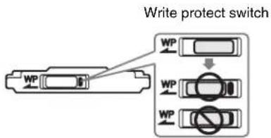
Note
Do not touch the write protect switch while an SxS memory card is loaded in a memory card slot. Eject the card before setting the write protect switch.
Inserting/removing an SxS memory card
Notes
- If for any reason an error should occur in an SxS memory card, the card must be restored before use.
- When an SxS memory card needing restoration into this unit, the restoration is executed automatically.
- Write protected SxS memory cards and cards on which memory errors have occurred cannot be restored.
- If you eject an SxS memory card from this unit while recording on it is proceeding, that card needs to be subjected to a salvage. Simply insert the card into the unit, and then salvage is executed automatically.
For details, see "Handling of SxS memory cards when recording does not end normally (salvage functions)" (page 47).
- When you use a “Memory Stick” adapter or SD card adapter, check to be sure that this unit is in operative state before inserting the combined media and adapter.
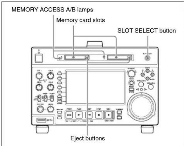
To insert an SxS memory card
Insert the SxS memory card into the card slot.
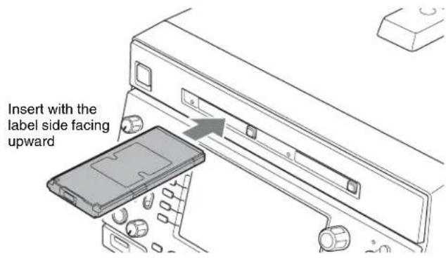
The lamp lights in orange then changes to green once the memory card is ready for use.
Status indications by the MEMORY ACCESS A/B lamps
Card slots A and B are accompanied by the respective lamps to indicate their statuses.
| Lamp Slot statuses |
| Lights in orange A | accessing the loaded SxS memory card (writing/reading data) |
| Lights in green Standby (ready for recording or playback using the loaded SxS memory card) |
| Off The slot is not | selected. |
Note
If an SxS memory card is inserted into the unit and is not recognized, temporarily eject the SxS memory card, check it for any substance adhering to the memory card, and then reinsert it. The memory card may become recognized when reinserted.


To remove an SxS memory card
1 Press the eject button to release the lock, then pull the button out.
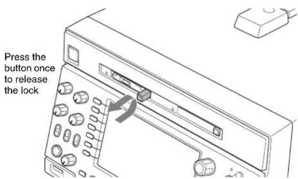
2 Press the eject button again to remove the card.
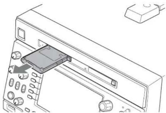
natural_image
Line drawing of a device's internal structure showing a central component and surrounding ports (no text or symbols)
Note
Data are not guaranteed if the power is turned off or a memory card is removed while the card is being accessed. All data on the card may be destroyed. Be sure that the MEMORY ACCESS A/B lamps are lit in green or off when you turn off the power or remove memory cards.
Switching between SxS memory cards
When SxS memory cards are loaded in both memory card slots A and B, press the SLOT SELECT button to select the card you wish to use.
Note
The SLOT SELECT button is disabled while copying is in progress, that is, switching is not executed even if you press the button.
To use an unused SxS memory card on this unit, you need to format (initialize) it first.
For details, see "Formatting (initializing) SxS memory cards" (page 68).
Handling an External Storage
You can connect a USB mass storage class device (a hard disk drive for example) to the Super Speed USB connector (USB 3.0 compatible) on the front panel and use it as an external storage for storing clips and other materials (capacity: 3 GB to 2 TB).
Note
The operation of all hard disk drives is not guaranteed. For information about recommended devices, consult your Sony dealer.
It is possible to create up to 99 folders on the external storage. Each folder can contain up to 1200 clips (not exceeding the total material length of 24 hours) and up to 99 EDLs.
The file system that the external storage supports is exFAT only.
Notes on use of an external storage
- Only one external storage device can be recognized. The device may not be recognized if a hub is used. Connect the device directly, without the use of a hub.
- Use an external storage with sector size of 512 bytes or 4 KB. External storages with other sector size may not be recognized by this unit.
- The external storage cannot be used at the same time with an SxS memory card loaded in card slot B. When using the external storage, remove the SxS memory card from card slot B.
- When using an external storage, mount the USB drive so that it can be recognized by this unit. If mounting failed, a message appears prompting you to format the external storage on this unit (see page 43).
- When removing the external storage, first dismount the USB drive (see page 44). After removing the external storage, you can now load an SxS memory card in the memory card slot B.
- If an external storage needs formatting, make sure to format it on this unit. If the external storage is formatted on a different device, it may not be recognized or it is treated as write protected on this unit.
-
When the total number of files recorded on an external storage exceeds 12000, further data writing on the same external storage by this unit is impossible. When the total number of files recorded on an external storage exceeds 20000, this unit cannot read data from that external storage. To use this unit with external storage, keep in mind these limitations on number of files.
-
It is not possible to play back clips stored on the external storage directly as they are. First copy the clips you want to play back to an SxS memory card, and then you can play back those copied clips from the SxS memory card (see page 44).
- If you copy clips to a folder on a USB drive and then delete or rename clips in that folder, you may not be able to perform additional copying.
- If data is written to the external storage from a device other than this unit, writing from the unit may become disabled.
Using the external storage
When using an external storage, mount the USB drive so that it can be recognized by this unit, and then mount a target folder.
To mount a USB drive
1 Connect the external storage to the Super Speed USB connector (USB 3.0 compatible) on the front panel.
2 In the Clip F Menu in the clip list screen, press F1: USB DRV (OFF) (see page 61).
The processing for USB drive mounting starts. When the USB drive gets mounted, the "OFF" indication under F1: USB DRV changes to "ON" and the icon for USB DRIVE ON ( ) appears in the status display area of the display screen. If there are folders in the USB drive, they are also displayed in the display screen.
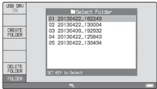
If you failed to mount the USB drive
A message appears prompting you to format the external storage.
To execute formatting, select "OK", and then press the PUSH SET knob. To cancel formatting, select "CANCEL", and then press the PUSH SET knob.
When the formatting is completed, the message “Format was successful.” appears.

Note
If formatting is executed, all existing partitions (including multipartitions) are deleted and initialized into one single partition.
To mount a target folder
Select the folder, and press the PUSH SET knob.
The processing for folder mounting starts.
On completion of the mounting, the thumbnails of or a list of stored clips in that folder are displayed.
To create a new folder
Press F3: CREATE FOLDER.
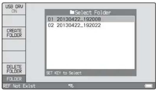
You can use F4: CREATE USB FLDR in the Clip F Menu (see page 60) to create a copy destination folder before executing a copy operation.
The newly created folder is automatically mounted.
To delete a folder in the USB drive
1 With the folders in the USB drive displayed in a list view, select the folder you want to delete.
2 Press F6: DELETE FOLDER.
A message appears asking you whether to delete the folder.
3 To execute deleting, select "OK" and then press the PUSH SET knob. To cancel deleting, select "CANCEL" and then press the PUSH SET knob.
To dismount the target folder
In the Clip F Menu, press F2: SELECT FOLDER (see page 61).
The target folder is dismounted, and the folders in the USB drive are displayed in a list view.
To use the external storage to copy clips
For more information about copy operations, see "Copying" (page 52).
To copy clips stored on the external storage
1 Mount the USB drive.
2 Mount the folder containing clips you want to copy.
3 Perform the procedure described in "Copying clips" (page 53).
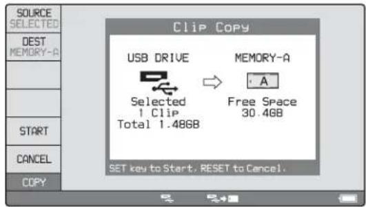
To copy clips to the external storage
1 Mount the USB drive.
2 Mount the copy destination folder, or create a new folder after selecting the clip to copy (see page 44).
3 Perform the procedure described in "Copying clips" (page 53).
Removing the external storage
First dismount the USB drive, and then removing the external storage.
To dismount the USB drive
In the Clip Menu in the clip list screen, press F1: USB DRV (ON).
The processing for dismounting starts.
On completion of the dismounting, the "ON" indication under F1: USB DRV changes to "OFF" and the USB DRIVE ON icon ( ) disappears from the status display area of the display screen.
Recording, Playback and Copy
Chapter
4
Recording
This section describes video and audio recording on the unit.
See page 37 "Basic Operations of the Function Menu" in Chapter 3 for more information.
See page 76 "Menus" in Chapter 7 for more information about setup menu operations.
Preparations for recording
Make the following settings and adjustments before starting to record.
Video input signal selection: Select with V INPUT on page P1 INPUT of the function menu.
Audio input signal selection: Select with from A1 INPUT to A4 INPUT on page P1 INPUT, and from A5 INPUT to A8 INPUT on page P2 INPUT of the function menu.
Timecode and user bits settings: See “Setting Timecode” (page 33).
Selection of time data to display: Select with CNTR SEL on HOME page of the function menu.
Selection of audio channels to monitor: Select with MONITR R and MONITR L on the HOME page of the function menu.
Volume adjustment of the monitor audio: Adjust with the LEVEL knob.
Remote/local setting: Set the remote control switch. If you set it to REMOTE, also set setup menu item 214 REMOTE INTERFACE ("RM-" and the connector used appear on the system information of the display) (see page 84).
File system of SxS memory card
Use an SxS memory card formatted in UDF or exFAT.
SD up-convert function
You can input SD signals to the SD/HDSDI INPUT connector and record them as HD signals.
Carrying out recording
One recording segment (from the start to the end of recording) is called a “clip”.
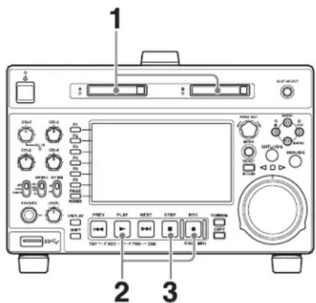
1 Insert an SxS memory card.
2 Hold down the REC button, and press the PLAY button.
Recording starts.
3 To stop recording, press the STOP button.
If the SxS memory card becomes full
Recording stops and the message “ALARM MEDIA END.” appears on the monitor.
Notes
- When you carry out recording in XAVC format, use an SxS memory card formatted in exFAT.
- The shortest clip that can be recorded is 2 seconds long. Even if recording start and stop operations are performed within 2 seconds, a 2-second clip is recorded.
- The maximum number of clips that can be recorded is 600. If the loaded SxS memory card already contains 600 clips, recording operation is not possible. (The message “MAX # Clips” appears in the time data display area.)
- This unit can record video input signals that are not synchronized to a reference signal. However, in that case, video breakup and audio noise may occur in EE playback.
- During recording, do not turn off the POWER switch on the rear panel or disconnect the power cord. This could cause the clip being recorded to be lost.
For details, see “Handling of SxS memory cards when recording does not end normally (salvage functions)” (page 47).
To adjust the audio recording levels
When carrying out audio recording at a reference level
Set the VARIABLE switch to "PRESET".
The audio signals will be recorded at a preset reference level.
You can change the reference level and the input levels with maintenance menu.
For details, refer to maintenance menu item M37 (page 95).
Manually adjusting the audio recording levels
Set the VARIABLE switch to “REC” and use the CH-1/ALL CH and CH-2 to CH-4 knobs to adjust CH-1 to CH-4, and use A5 VOL to A8 VOL on page P3 AUDIO of the function menu to adjust CH-5 to CH-8 so that the audio level indications on the audio level meters do not exceed 0 dB for a maximum volume.
See setup menu item 108 AUTO EE SELECT (page 83) for more information about the signal output settings in EE mode.
To set shot marks
A Shot Mark1 essence mark or Shot Mark2 essence mark is set if you hold down the ♦/MARK1 or ♦/MARK2 button and press the PUSH SET knob during recording. If the unit is set up to display superimposed text information (see page 35), “SHOTMARK*” (*: 0 to 9) appears every time you set an essence mark.
When Shot Mark0 to Shot Mark9 is set, you can search for the shot marks by displaying thumbnails of the frames at those positions (see page 61).
You can also set shot marks during STILL (still picture mode). See page 50 for the procedure.
Continuing to record while exchanging memory cards (relay recording)
When SxS memory cards are inserted in both memory card slots A and B, the unit automatically switches from the memory card in slot A (or slot B) to the memory card in the other slot, just before the remaining recording capacity of the memory card runs out, and continues recording. You can also switch between memory cards at any time during recording by pressing the SLOT SELECT button.
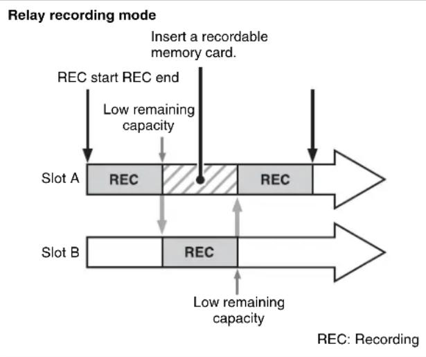
flowchart
graph TD
    A["REC start REC end"] --> B["Low remaining capacity"]
    B --> C["Insert a recordable memory card."]
    D["Slot A"] --> E["REC"]
    E --> F["Low remaining capacity"]
    G["Slot B"] --> H["REC"]
    H --> I["Low remaining capacity"]
    style D fill:#f9f,stroke:#333
    style G fill:#f9f,stroke:#333
Settings
Set setup menu item 039 RELAY REC MODE to "on".
Notes
- Always use memory cards with sufficient remaining recording capacity for correct relay recording operation.
- Relay recording is supported only when the memory cards in both slots A and B use the same file system (UDF or exFAT).
- The maximum length of a clip is six hours. If the recording time exceeds the maximum clip length, a new clip is created and recording continues.
- Do not remove a memory card while it is recording. When exchanging memory cards during recording, only exchange the memory card in the slot for which the MEMORY ACCESS lamp is not lit.
- You cannot switch between memory cards by pressing the SLOT SELECT button during playback.
In relay recording mode, you can format an SxS memory card during recording.
For details, see "To format (initialize) an SxS memory card during recording" (page 69).
Recording with the HDSDI remote control function
This section explains the settings required for recording in HDSDI remote control mode, and how the unit operates in this mode.
Note
The unit (camcorder) that controls this unit must also support HDSDI remote output.
Settings
Set setup menu item 214 REMOTE INTERFACE to "SDI", and set the remote control switch on the front panel to "REMOTE".
This unit enters HDSDI remote control mode, in which it is controlled by command packets received via the SD/HDSDI INPUT connector.
Note
Commands received via the REMOTE (9P) connector are ignored in HDSDI remote control mode.
Monitor display in HDSDI remote control mode
“RM-SDI” appears as network remote connection display (see page 17) in the status display area of the display screen. This display lights if command packets are embedded into HDSDI signals, and flashes if they are not. However, the “RM-SDI” continues to flash until the time the controlling camcorder is powered on and the time that the REC button is pressed on the camcorder.
Recording operation
When a recordable SxS memory card is inserted, recording (or stop) is executed according to the REC (or STOP) command embedded into the HDSDI signals. Recording stops automatically when the end of the SxS memory card is reached.
When HDSDI signals are interrupted during recording
Recording stops if HDSDI signals are interrupted during recording, for example because the HDSDI cable is disconnected or the controlling camcorder is powered off. When HDSDI signal input is restored, the unit resumes operation according to the embedded REC or STOP command.
During recording, you cannot exchange from the currently used SxS memory card to another.
To exchange, first stop the recording. Then press the SLOT SELECT button to swap slots, or remove the SxS memory card and insert a different one.
After an SxS memory card is exchanged, the unit resumes operation according to the REC or STOP command embedded in the HDSDI signal.
If an SxS memory card is removed when a clip is being recorded on it, the quality of that clip is not guaranteed.
For details, see “Handling of SxS memory cards when recording does not end normally (salvage functions)” (page 47).
Note
This unit begins recording operation about one second after the camcorder.
Handling of SxS memory cards when recording does not end normally (salvage functions)
Recording processing does not end normally if one of the following is performed during recording.
• The POWER switch on the rear panel is turned off.
• The power cord is disconnected.
• The SxS memory card is ejected.
- The write-protect switch is set to "WP."
Because the file system is not updated, video and audio data recorded in real time is not recognized as files and clip contents recorded up to that point are lost.
However, this unit has salvage functions which can hold losses to the minimum by reconstructing clips on such SxS memory cards.
Notes
- Even after recording finishes, do not set the POWER switch on the rear panel to off until the MEMORY ACCESS lamp has lit green.
• These functions salvage as much recorded material as possible after an unforeseen accident, but 100% restoration cannot be guaranteed.
- Even when these functions are used, it is not possible to recover data from immediately before the interruption of recording. The amount of data that will be lost depends on the video format (maximum 20 seconds of data before the interruption of recording).
- When you insert an SxS memory card that cannot be salvaged, or power the unit on with such SxS memory card loaded, the following warning message appears in the Status display area of the display screen.
Memory(A) needs Restoring (when slot A is selected)
- No recording is possible on SxS memory cards containing clips that have not been salvaged, although it is possible to play back the normally recorded sections. Recording becomes possible if you perform a format, but this erases all of the original recorded content.
To restore clips via salvage
When you insert an SxS memory card on which recording did not end normally, salvage will be performed automatically.
Playback
This section describes playback of video and audio on the unit.
Before starting playback, make the following settings and adjustments.
Selection of time data to display: Select with CNTR SEL on the HOME page of the function menu.
Selection of audio channels to monitor: Select with MONITR L and MONITR R on the HOME page of the function menu.
Volume adjustment of the monitor audio: Adjust with the LEVEL knob.
Remote/local setting: Set the remote control switch. If you set it to REMOTE, also set setup menu item 214 REMOTE INTERFACE (“RM-” and the connector used appear on the display) (see page 84).
Clip playback modes
You can set the clip playback mode to either of the following.
Continuous playback mode: The playback target is all of the clips on the SxS memory card (factory default setting)
Single clip playback mode: The playback target is the currently selected clip only
To select single clip playback mode
Set setup menu item 154 SINGLE CLIP PLAY MODE to "on".
Playback in single clip playback mode
The available playback types include normal playback, high-speed playback in the forward or reverse directions, and jog, shuttle, and variable playback. Playback stops when it reaches the start or end of the clip. The next and preceding clips are not played, even if they exist on the SxS memory card.
When this unit is set to repeat playback mode, the selected clip only is played repeatedly.
To move to another clip, press the PREV, NEXT, SHIFT + PREV, or SHIFT + NEXT button, or perform a thumbnail search.
Playback start position of SxS memory cards
Although this unit uses SxS memory cards, it is designed to offer the most convenient features of tape playback on VTRs. The playback start position of content on SxS memory cards varies, as described below.
After playback stop
The unit stops at the position where the STOP button was pressed.
Press the PLAY button to resume playback at the stop position.
After recording
The unit stops at the position where recording ended.
To play back a clip, press the PREV button to move to the start frame of any clip or press the PREV button with the PLAY button held down to move to any position.
Note
This function is not available if:
- the write protect switch on the loaded SxS memory card is set to the WP side, or
- the recording format of the loaded SxS memory card is FAT32.
SD up-convert function
The content of SxS memory cards recorded in SD can be output as HD.
HD down-convert function
You can always output SD while playing SxS memory cards recorded as HD.
1080/720 cross convert function
You can output 720 while playing clips recorded as 1080, and output 1080 while playing clips recorded as 720. When the system frequency of clips (59.94i/59.94P/29.97P, 23.98P, or 50i/50P/25P) matches the system frequency of the unit, but the number of system line settings (1080 or 720) do not match, then clip playback is cross converted automatically.
In cross convert mode, "FC" is displayed.
Pulldown playback
When this unit's system frequency is set to 1080/59.94i, 1080/29.97P, or 720/59.94P, clips recorded as 1080/23.98P or 720/23.98P are converted by 2-3 pulldown before playback (pulldown playback).
Note
When the unit is in continuous playback mode and some clips are selected for pulldown playback, continuous playback of the selected clips is performed in the specified format of pulldown playback (1080/23.98P or 720/23.98P).
Timecode in pulldown playback
During pulldown playback, timecode is also converted to 30-frame timecode to match the output video signals.
The upper row of the time data display area displays the original 24-frame timecode, and the lower row displays the 30-frame timecode.

You can superimpose the 30-frame timecode after pulldown on an external monitor. To do so, set setup menu item 005 DISPLAY INFORMATION SELECT to “time data only”.

Playback operation
This section describes the following types of playback:
Normal playback: Playback at normal speed
Playback in jog mode: Variable-speed playback, with the speed determined by the speed of turning the jog dial
Playback in shuttle mode: Variable-speed playback, with the speed determined by the angular position of the shuttle dial
Playback in variable mode: Variable-speed playback, with the speed finely determined by the angular position of the shuttle dial
Normal playback
First insert an SxS memory card.
For details of how to insert an SxS memory card, see "Inserting/removing an SxS memory card" (page 41).
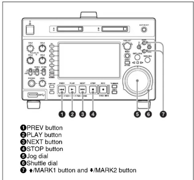
To start playback
Press the PLAY button in continuous playback mode. Playback starts.
When two or more clips are recorded on the SxS memory card, they are played back continuously.
Notes
- No sound is output when non-audio signals are played back.
- Clips recorded in the XAVC Long 50/35/25 Mbps recording format cannot be played continuously (continuous playback) with clips recorded in other formats.
To jump to the next or previous clip, then start playback
Use the PREV button, NEXT button, jog dial, or shuttle dial.
To stop playback
Press the STOP button.
If you play back to the end frame of the last clip, playback automatically stops.
If, in this state, you press the PLAY button, the message "Media End!" appears on the display.
To carry out playback again, move back to the desired clip using the PREV button, jog dial or shuttle dial.
To set shot marks
During STILL (still picture mode), you can set essence marks such as Shot Mark1 and Shot Mark2 in desired frames.
To set a Shot Mark1 or Shot Mark2, hold down the ♦/MARK1 or ♦/MARK2 button and press the PUSH SET knob.
You can also delete and modify essence marks from the Thumbnail Menu of the chapter thumbnail screen (see page 62).
Note
Shot marks cannot be set to a locked clip.
Playback in jog mode
In jog mode, you can control the speed of playback by the speed of turning the jog dial. The playback speed range is -1 to +1 times normal speed.
To carry out playback in jog mode, proceed as follows.
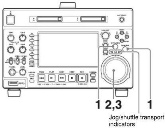
1 Press the SHTL/JOG button or VAR/JOG button, turning it on.
When the SHTL/JOG or VAR/JOG button is pressed during recording, recording stops and the unit enters jog mode. If you do not want to stop recording, set setup menu item 145 MODE KEY ENABLE DURING RECORDING to "stop".
2 Turn the jog dial in the desired direction, at the speed corresponding to the desired playback speed.
Playback in jog mode starts.
The Jog/shuttle transport indicators light as follows.
◀ (green): Lights during playback in the reverse direction.
▶ (green): Lights during playback in the forward direction.
3 To stop playback in jog mode, stop turning the jog dial.
When setup menu item 101 SELECTION FOR SEARCH DIAL ENABLE is set to "dial" (factory default setting), you can start jog playback by simply rotating the jog dial, even when the SHTL/JOG and VAR/JOG buttons are not lit.
Playback in shuttle mode
In shuttle mode, you can control the speed of playback by the angular position of the shuttle dial. The range of playback speed is ±20 times normal speed or maximum speed.
To carry out playback in shuttle mode, proceed as follows.
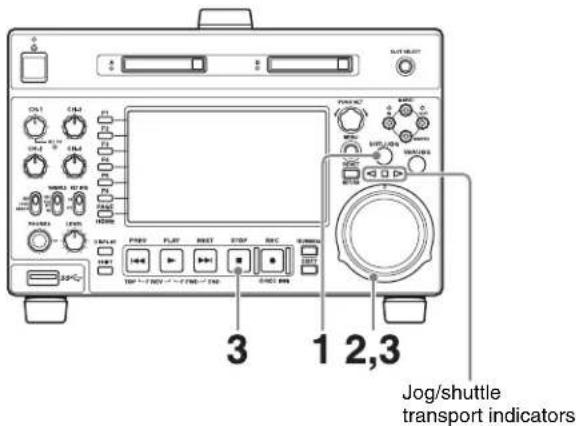
1 Press the SHTL/JOG button, turning it on.
When the SHTL/JOG button is pressed during recording, recording stops and the unit enters shuttle mode. If you do not want to stop recording, set setup menu item 145 MODE KEY ENABLE DURING RECORDING to "stop".
2 Turn the shuttle dial to the desired angle corresponding to the desired playback speed.
Playback in shuttle mode starts.
The shuttle dial has a detent at the center position, for still image playback.
The Jog/shuttle transport indicators light as follows.
◀ (green): Lights during playback in the reverse direction.
▶ (green): Lights during playback in the forward direction.
■ (red): Lights during still image display.
3 To stop playback in shuttle mode, return the shuttle dial to the center position, or press the STOP button.
When setup menu item 101 SELECTION FOR SEARCH DIAL ENABLE is set to "dial" (factory default setting), you can start shuttle playback by simply rotating the shuttle dial, even when the SHTL/JOG button is not lit.
Notes
- When setup menu item 101 SELECTION FOR SEARCH DIAL ENABLE is set to "dial", after using the shuttle dial, return it to the center position. If the shuttle dial is not in the center position, it is possible occasionally for vibration from other operations to activate the dial, and start playback in shuttle mode.
- Video and audio become discontinuous if you conduct shuttle playback of a clip that does not include the proxy AV data in the media.
To alternate between normal-speed playback and shuttle mode playback
Set the shuttle dial to the position corresponding to the desired shuttle playback speed, then switch between normal-speed playback and shuttle playback by pressing the PLAY and SHTL/JOG buttons alternately.
Playback in variable mode
In variable mode, you can control the speed of playback in the range of -2 to +2 times normal speed by the angular position of the shuttle dial.
To carry out playback in variable mode, proceed as follows.
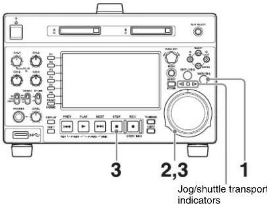
1 Press the VAR/JOG button, turning it on.
When the VAR/JOG button is pressed during recording, recording stops and the unit enters variable mode. If you do not want to stop recording, set setup menu item 145 MODE KEY ENABLE DURING RECORDING to "stop".
2 Turn the shuttle dial to the desired angle corresponding to the desired playback speed.
Playback in variable mode starts.
The shuttle dial has a detent at the center position, for still image playback.
The Jog/shuttle transport indicators light as follows.
◀ (green): Lights during playback in the reverse direction.
▶ (green): Lights during playback in the forward direction.
■ (red): Lights during still image display.
3 To stop playback in variable-speed mode, return the shuttle dial to the center position, or press the STOP button.
To alternate between normal-speed playback and variable mode playback
Set the shuttle dial to the position corresponding to the desired variable playback speed, then switch between normal-speed playback and variable mode playback by pressing the PLAY and VAR/JOG buttons alternately.
Playback operations using thumbnails
Playback operations that you can perform with thumbnails include searching for clips, displaying clip information, playing clip lists created, and locking and deleting clip. This allows you to check the actual video as you work.
See “Clip Operations” (page 61) for more information about thumbnail.
Copying
Overview
This unit enables a copy of clips, EDLs, and files to another SxS memory card or the external storage. A copy of those stored in the external storage to the SxS memory card is also possible.
By copying clips/EDLs on an SxS memory card to another SxS memory card or the external storage, you can reuse the SxS memory card as recording media. This is a convenient practice for long hours shootings using XDCAM/XDCAM EX camcorders.
MP4/MXF/AVI clips on an SxS memory card are copied as follows.
MP4/AVI clips: Clips in MP4 format are converted to MXF clips ^1) and copied to the MXF clip recording area managed by this unit. The copied clips can be handled as normal clips.
MXF clips: Clips in MXF format are copied with no format conversions to the MXF clip recording area managed by this unit. The copied clips can be handled as normal clips.
1) The quality of video and audio data is not degraded.
For information about operations, see next section "Copy operations".
Limitations
- When you copy a clip with a duration that exceeds six hours, the clip is divided into separate clips at each six-hour point.
- Essence marks are limited to one per second when you convert and copy from the MP4 format to the MXF format.
- Index picture settings may be displaced forward or backward when you execute a copy.
- When an MXF clip is copied, the UMID data of the copy source clip is maintained intact. If the copy destination media contains a clip with same UMID data as the clip selected as copy source, it is not possible to copy the selected clip. Change UMID data on an external device, or make transfer of the copy source clip via the network. When an MP4/AVI clip is copied, new UMID data is automatically generated and added to the copy source clip. Therefore, copying is possible even if on the copy destination there is a clip with same UMID data as the copy source clip.
- Seamless playback and clip flag operations (addition, modification, and deletion) are not supported for MXF clips and for independent AV files (files without
metadata, consisting of video and audio data only) that meet the following conditions.
- Clips containing 1000 or more essence marks
- Clips containing 10804 or more timecode breaks
- Clips with metadata files *M01.XML more than 2 MB in size
Copy operations
Copying clips
To copy between SxS memory cards
To copy from the SxS memory card (in the slot A) to the external storage
To copy from the external storage to the SxS memory card (in the slot A)
1 Insert an SxS memory card into a memory card slot.
When two SxS memory cards are loaded
Press the SLOT SELECT button to switch between the target cards (A/B).
Note
For copy between the SxS memory card and the external storage, select slot A.
2 Select the media containing target clips, and press the THUMBNAIL button.
The clip list screen appears.
To change the folder for displaying thumbnails
Press the function button (F3) and select the folder to display thumbnails.
Example: To display thumbnails of MPEG-4 AVC/H.264-format recorded clips, press the function button (F3) and select XDROOT.
3 Do one of the following to select the clip to copy.
- Turn the PUSH SET knob.
- Press the arrow buttons.
To select several continuous clips
Move the cursor to the start or end of the clips that you want to select, and then proceed as described above while holding down the SHIFT button.
When copying all clips on the SxS memory card
Proceed to step 4 without carrying out clip selection operation.
To copy part of a clip
When you select a single clip and press the arrow buttons to set an IN and OUT point in the clip, it becomes possible to copy the section defined by the IN and OUT points.
On how to set an IN and OUT point, see “To copy the specified part of a clip” (page 54).
4 Press the COPY button.
The Clip Copy screen appears.
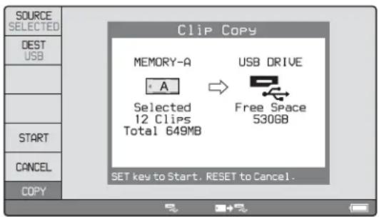
To change the copy source clip
Press the RETURN button to return to the clip list screen, and then select another clip.
To cancel the copy operation
Press the CANCEL function button (F6) or the RESET button.
5 Press the SOURCE function button (F1) and select "SELECTED", "ALL", or "PARTIAL".
To copy the clips selected in step 3: Select "SELECTED".
To copy all the clips on the SxS memory card: Select "ALL".
6 Press the START function button (F5).
Copying of the clips starts.
The progress of the copying is shown in the Clip Copy screen, and the copy icon lights in the status display area.
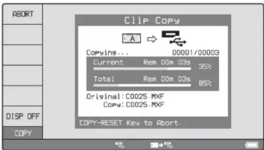
To abort the copy operation
Press the ABORT function button (F1), and then press the YES (F5) button.
The data having already been transferred to the destination media remains on that media.
If the copy operation is completed successfully, the message “Copy was Completed.” appears.
The Clip Copy screen disappears, and you return to the original screen.
To copy an EDL file
An EDL can be copied by an operation similar to a clip copy operation. However, it is necessary to make a copy of all clips referenced by the EDL in advance. Therefore, "ALL" is automatically selected in step 3 of the procedure for "Copying clips" (page 53).
To copy the specified part of a clip
When you set an IN and OUT point in the clip, it becomes possible to copy only the part defined by the IN and OUT points.
1 In the video monitor screen, cue the clip up to the frame where you want set an IN point.
2 Press the PUSH SET knob while holding down the ←/IN button.
An IN/OUT setting window appears in the bottom right corner of the display.
The IN point timecode is displayed in the IN/OUT setting window, and the IN indicator lights.
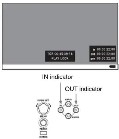
3 Cue up to the frame where you want to set an OUT point.
4 Press the PUSH SET knob while holding down the ➤/OUT button.
An IN/OUT setting window appears in the bottom right corner of the display.
The OUT point timecode and the duration (DUR) are displayed in the IN/OUT setting window, and the OUT indicator lights.
5 Carry out step 4 and following of the procedure for "Copying clips" (page 53).
To check the clip with IN and OUT points set
1 Press the ←/IN or →/OUT button.
An IN/OUT setting window appears in the lower right of the display.
2 Press the NEXT or PREV button.
The unit cues up the frame with the IN (or OUT) point set.
To delete the IN/OUT points
1 Press the ←/IN button (or →/OUT button).
The IN/OUT setting window appears in the bottom right corner of the display.
2 Press the RESET button.
The IN (or OUT) indicator turns off.
Note
One of the following operations deletes the IN/OUT points automatically.
- Change the selection of media.
- Remove the media.
- Delete the clip in which IN/OUT points are set.
- Format the media.
Operations in Clip List Screens
Chapter
5
Overview
Use clip list screens to search for scenes, play scenes found by searching, select clips to copy, and perform other operations related to clips.
You can switch between the details view and the thumbnails view of clip list screens.
Switching between display screens
To switch between the basic operation screen, video monitor screen, and clip list screens (thumbnails view and
details view), press the THUMBNAIL button (①) or DISPLAY button (②).
The screens change as shown in the following figure.

a) Switches back to the screen that was displayed before the last transition.
Thumbnails view
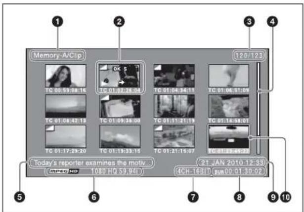
① Clip storage locations
Display the storage location of the currently displayed clips and EDLs in the format “recording media/folder”. On this unit, one of the following appears.
Memory-A/Clip: Clip folder on the SxS memory card in slot A
Memory-B/Clip: Clip folder on the SxS memory card in slot B
②Thumbnail
Thumbnail of a clip or an EDL icon.
Thumbnails of clips and EDL icons can be displayed in the same clip list screen, but clip thumbnails are displayed in first.
For details, see "Thumbnail display items" (page 57).
③ Clip number/total number of clips
Displays the total number of clips (including EDLs) on the selected media, and the number of the selected clip (or EDL).
When not all of the thumbnails can be displayed in the thumbnail display area, the position of the slider shows the relative position of the currently displayed clips, and the length of the slider shows the relative length of currently displayed clips within all of the clips.
⑤ Clip name
Displays the name of the selected clip (or EDL).
When multiple clips are selected, displays the name of the first clip or the most recently selected clip.
Clip names can be displayed in European languages (English, French, German, Italian, etc.), Japanese, Hangul characters, and Chinese (both simplified and traditional characters).
Notes
- Every character that cannot be displayed properly is represented by a ■.
- Too long a clip name is not fully displayed. To check the entire character string of the name, access the Clip Properties screen (see page 57).
The video format of the selected clip is displayed as a combination of the following items.
• Video format logo
• Number of system lines and recording quality
- System frequency
The audio format of the selected clip is displayed as a combination of the following items.
• Number of audio channels
• Quantization bit rate
⑧ Duration
Displays the duration (recording time) of the selected clip. When multiple clips are selected, displays the total recording time of the selected clips.
⑨Clip date and time
Displays the date and time when the selected clip was shot and recorded.
⑩Selection frame
Indicates that the clip is selected. To select another clip, move the frame (see page 61). Multiple selection frames appear when multiple clips are selected (see page 61).
Details view
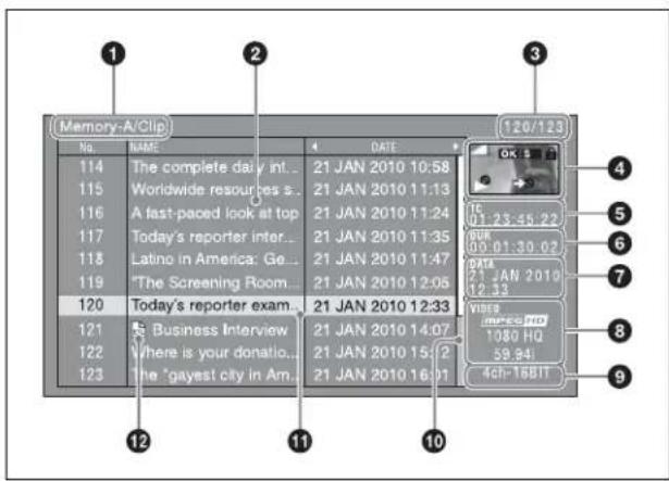
For details about the following items, see “Thumbnails view” (page 56).
① Clip storage locations
③ Clip number/total number of clips
⑥ Duration
⑦ Clip date and time
⑧Video format
⑨ Audio format
⑪ Selection frame
②Details display area
Displays a details list of clips and EDLs on the selected media.
The list is made up of the following columns.
• No. (line number)
- NAME (clip name)
• DATE (clip date and time)
• DURATION (recording time)
④Thumbnail
Displays the thumbnail of the selected clip (or the EDL icon when an EDL is selected).
For details, see "Thumbnail display items" (page 57).
⑤ Timecode
Displays the starting timecode of the selected clip.
When not all of the clips can be displayed in the details display area, the position of the slider shows the relative position of the currently displayed clips, and the length of the slider shows the relative length of currently displayed clips within all of the clips.
⑪EDL mark
The mark 📄 appears when the item is an EDL.
Clip Properties screen
When you select a clip and press the CLIP PROPERTY function button (F2), a screen is displayed to show the properties of the selected clip.
To change the selected clip, use the NEXT/PREV button (or press them while pressing the SHIFT button) (see page 61).
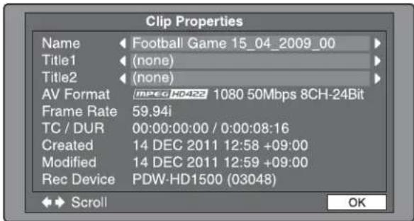
Name: Clip name 1)
Title1: Title1
Title2: Title2 1)
AV Format: Recording format
Frame Rate: The frame rate at the time when the clip was shot. For clips shot using Slow & Quick Motion, the PB (playback)/Capture (shooting) frame rates are shown.
TC/DUR: Timecode of the first frame/Recording time
Created: Date and time of creation
Modified: Date and time of most recent modification
Rec Device: Name of device that created the clip (product number)
1) See "Clip name" in "Thumbnails view" (page 56).
The Clip Properties screen displays the entire character string of even a rather long clip name or title.
When a ◀ or ▶ mark is displayed for an item, you can press the left arrow or right arrow button to scroll the display by one character for each press.
The up arrow and down arrow buttons scroll the beginning and end of the string into view.
When there is any hidden part of the string, arrows are displayed on the left and right of the "Scroll" indication at the bottom left of the screen.
Thumbnail display items
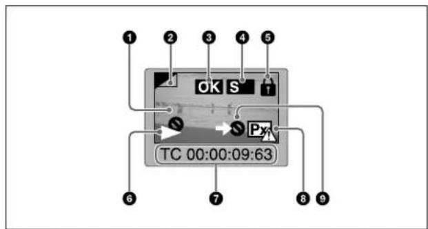
Note
Only ⑥ and ⑨ are displayed on the EDL icon.
①Index picture
Displays an image to stand for the content of the clip. Normally the index picture is the first frame in a clip, but you can change it to any frame in the clip for a different index picture.
For the method of changing the index picture frame, see "Setting the index picture frame" (page 64).
②Index picture changed mark
This mark, like the folded-over corner of a page that you want to remember, appears when the index picture has been changed to any frame other than the first frame of a clip.
Note
When you cue up a clip, the unit always cues up the first frame, even when the index picture has been changed to a different frame.
③ Clip flag icon
Displays the corresponding icon when a clip flag (OK/NG/KP(KEEP)) is set in the clip (see page 63).
④S mark
This mark appears when shot marks or other essence marks have been set in the clip.
⑤Lock icon
This icon appears when the clip is locked (protected) (see page 63). Clips cannot be deleted and their clip information cannot be changed when this mark is displayed.
⑥ Unplayable icon/copy playback icon
An unplayable icon ( )appears to indicate that the clip cannot be played (or EDL), for example because the system frequency settings differ from the current settings of this unit.
Displays the clip information selected with the CLP INFO item in the Clip F Menu (see page 60). The factory default selection is the timecode of the first frame.
⑧“No proxy AV data” icon
This icon appears when the clip does not include proxy AV data.
⑨“Cannot copy” icon
You cannot copy clips (or EDL) marked with this icon.
Expand thumbnail screen
This screen displays thumbnails of equally sized divisions of the selected clip or EDL.
On how to display the expand thumbnail screen, see "To search through a clip in the expand thumbnail screen" (page 61).
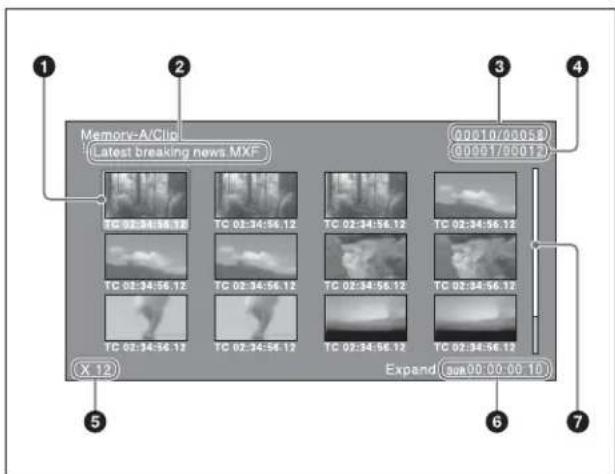
①Selection frame
Indicates that the thumbnail is selected. To select another thumbnail, move the frame (see page 61).
② Clip name
Displays the name of the clip displayed in the current expand thumbnail screen.
③ Clip number/total number of clips
Displays the total number of clips on the selected media and the number of the clip whose expanded thumbnails are currently displayed.
④Thumbnail number/total number of thumbnails
Displays the total number of thumbnails of the divided clip and the number of the currently selected thumbnail.
⑤Number of divisions
Displays the number of times that the selected clip has been divided to display the expand thumbnails.
⑥Duration
Displays the time from the selected thumbnail to the next one.
See the description of "Scrollbar" under "Thumbnails view" (page 56).
Chapter thumbnail screen
Chapters are the sections between the shot marks, Rec Start marks, and other essence marks that have been recorded in clips or EDL sub clips. This screen allows you to display thumbnails of the chapters in the selected clip or EDL.
On how to display the chapter thumbnail screen, see "To search through a clip in the chapter thumbnail screen" (page 62).
Rec Start essence marks are set automatically at the start of recording, but shot marks can be set at any scene during recording or STILL (still picture mode).
See page 46 and page 50 for more information about shot mark setting.
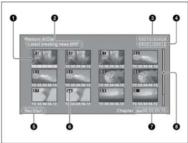
①Selection frame
Indicates that the thumbnail is selected. To select another thumbnail, move the frame (see page 61). Multiple selection frames appear when multiple thumbnails are selected (see page 61).
②Clip name
Displays the name of the clip displayed in the current chapter thumbnail screen.
③ Clip number/total number of clips
Displays the total number of clips on the selected media and the number of the clip whose chapter thumbnails are currently displayed.
④ Chapter number/total chapters
Displays the total number of chapters and the number of the selected chapter.
⑤ Essence mark indication
Displays the type of the essence marks which are set on the selected chapter.
“S0” to “S9” and “RS” marks on the thumbnails indicate frames where Shot Mark1 to Shot Mark9 and Rec Start essence marks are set. “S” marks indicate frames where essence marks other than shot marks and Rec Start essence marks are set.
No such marks are displayed on thumbnails of EDL sub clips.
⑦Duration
Displays the time from the first frame of the selected chapter to the first frame of the next chapter.
See the description of "Scrollbar" under "Thumbnails view" (page 56).
The Clip Menu provides the following commands for operations on clips.
The shortcut buttons shown in parentheses () allow you to open menu items directly. For example, combinations are indicated by “+”. “SHIFT + STOP” means to press the STOP button while holding down the SHIFT button.
| Item Sub-item Function | |
| Delete Clips (SHIFT + RESET) | Delete Selected Clips | Deletes the selected clips. |
| Delete All Clips | Deletes all clips on the selected media. |
| Lock Unlock Clips (SHIFT + STOP) | Lock Selected Clips | Locks the selected clips. |
| Lock All Clips | Locks all clips on the selected media. |
| Unlock Selected Clips | Unlocks the selected clips. |
| Unlock All Clips | Unlocks all clips on the selected media. |
| Set Clip Flag OK Sets the OK flags in the selected clips. |
|
|
|
|
| Format Media (UDF) | – Formats (initializes) an SxS memory card in UDF. |
| Format Media (exFAT) | – Formats (initializes) an SxS memory card/external storage in exFAT.NoteWhen formatting the external storage, mount the USB drive so that it can be recognized by this unit (see page 43). |
| Update/Restoring Media | – Rebuilds SxS | memory card management data. |
| Item Sub-item Function | | |
| Media Properties – | Displays informationabout the selected media. |
| Settings Select Clip | Language | Selects the clip name display language.• Alphabet• Korean• Simplified Chinese• Traditional Chinese• Japanese |
| Select Alarm Language | Selects the alarm display language.• English• Japanese |
Press the MENU button with a clip list screen (thumbnails view or details view) displayed.
To return to the original screen, press the MENU button again.
To move the focus bar up or down: Press the ↑/MARK1 or ↓/MARK2 button, or turn the PUSH SET knob.
To move from a menu level to the next lower menu level: Press the ➤/OUT button or PUSH SET knob.
To move from a menu level to the next higher menu level: Press the ←/IN button or RETURN button.
To execute a command: Press the PUSH SET knob.
The clip list screens provide the Clip F Menu, which can be accessed directly with function buttons.
Following is a list of Clip F Menu commands. Underlined settings are the factory defaults.
| Item Function | |
| F1: CLP INFOa) | Selects the information to be displayed at the bottom of the thumbnails.DATE: Date and time of creation, or date and time of the more recent modificationTC: Timecode of first frameDURATION: Playback timeSQ NO.: Sequence number of thumbnail |
| F2: CLIP PROPERTY | Displays the Clip Properties screen (see page 57). |
| F5: CHAPTER Displays the chapter thumbnail screen (see page 58). |
| F6: EXPAND Displays the expand thumbnail screen. |
a) Does not appear when the clip list screen is in details view.
CLIP page
| Item Function | |
| F1: CLP INFOa) | Selects the information to be displayed at the bottom of the thumbnails.DATE: Date and time of creation, or date and time of the more recent modificationTC: Timecode of first frameDURATION: Playback timeSQ NO.: Sequence number of thumbnail |
| F2: CLIP PROPERTY | Displays the Clip Properties screen (see page 57). |
| F3: FOLDER | When the USB drive has been mounted with an external storage connected to this unit, selects the folder in the USB drive whose content you want to display in the clip list screen. |
| F4: CREATE USB FLDR | When the USB drive has been mounted with an external storage connected to this unit, creates a copy destination folder in the USB drive to enable a clip on an SxS memory card to be copied to the external storage. (The name of the copy destination folder will automatically be the shooting date of the clip.)NoteThis operation cannot be executed if the USB drive is write inhibited.For the operation to write enable the USB drive, refer to the instruction manual for the external storage that you are using. |
| F5: CHAPTER Displays the chapter thumbnail screen (see page 58). |
| F6: EXPAND Displays the expand thumbnail screen. |
a) Does not appear when the clip list screen is in details view.
P1 EDL page
Parentheses ( ) indicate shortcut buttons for directly accessing a menu item.
| Item | Function |
| F1: SET CURT.EDL | Sets the current EDL. |
| F2: RELEASE CURT.EDL | Releases the current EDL. |
| F3: CREATE NEW EDL (SHIFT + PUSH SET knob) | Creates a new EDL. |
| F4: ADD TO CURT.EDL | Adds sub clips to the current EDL. |
| F6: GOTO CURT.EDL | Refers to the current EDL. |
If a clip that you want to become a sub clip is selected on a clip list display screen, you can invoke the F3: CREATE NEW EDL command by pressing and holding the SHIFT button and pressing the PUSH SET knob.
For the procedure for creating EDLs, see “Creating and editing EDLs” (page 66).
P2 OTHER page
| Item Function | |
| F1: USB DRV When an external storage is connected to this unit, executes USB drive mounting or dismounting.ON: The USB drive is mounted.OFF: The USB drive is not mounted. |
| F2: SELECT FOLDER | When the USB drive has been mounted with an external storage connected to this unit, displays a list of folders existing in the USB drive. |
Press the PAGE/HOME button or function buttons (F1 to F6) with a clip list screen (thumbnails view or details view) displayed.
To display a different page
Each press of the PAGE/HOME button displays the next function menu page in the order: CLIP → P1 → P2 → CLIP...
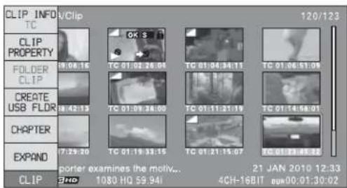
Clip Operations
Selecting clips
Select clips with the selection frame (see page 56).
To move the selection frame
Do one of the following.
- Turn the PUSH SET knob.
- Press the arrow buttons.
- Turn the shuttle/jog dial. (The selection frame moves at high speed in shuttle mode and at low speed in jog mode.)
- Press the NEXT/PREV button.
To jump to the first clip
Press the PREV button while holding down the SHIFT button.
To jump to the last clip
Press the NEXT button while holding down the SHIFT button.
To make a continuous selection of clips
Move the selection frame to the first clip that you want to select. Then, while holding down the SHIFT button, turn the PUSH SET knob.
To cancel the continuous selection, move the selection frame without the SHIFT button held down.
Searching with thumbnails
You can put the clip list screen into thumbnails view (see page 56) to search for desired clips while viewing thumbnails.
To search for clips while viewing clip names, press the DISPLAY button to switch to details view (see page 56).
To search through a clip in the expand thumbnail screen
The expand function allows you to divide a clip selected in the clip list screen into equally sized blocks, and to display a list of thumbnails of those blocks. This is a quick and efficient way to review the selected clip and search for target scenes. You can specify 12, 144, or 1728 divisions.
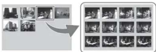
natural_image
Two grayscale images showing a person in a studio setting, one with a framed picture and arrow pointing to the right image (no text or symbols)
1 In the clip thumbnail screen, select the thumbnail of the clip that contains the scene you want to find.
2 Press the EXPAND function button (F6).
The selected clip is divided into 12 blocks, and a list appears in the expand thumbnail screen (see page 58) with the first frame of each block displayed as a thumbnail.
3 Select the thumbnail that you want to expand further.
4 Repeat steps 2 and 3 up to 2 times, as required.
Note
If the duration of each block after division would be shorter than one frame, division is performed so that an expand thumbnail screen is displayed in which the duration of each block is one frame. In this case, no such expand thumbnail screen is displayed that represents further expansion.
For example, a 100-frame clip is divided into 100 blocks when you press the EXPAND function button (F6) twice and an expand thumbnail screen is displayed in which the duration of each block is one frame. A third press of the EXPAND function button (F6) displays no expand thumbnail screen representing further expansion.
To return to the previous expansion level
Press the EXPAND function button (F6) while holding down the SHIFT button.
To display the expand thumbnail screen of the previous or next clip
With the expand thumbnail screen still active, press the PREV button or the NEXT button.
An expand thumbnail screen appears displaying the thumbnails of 12 equal blocks resulting from division of the previous or next clip.
To search through a clip in the chapter thumbnail screen
The chapter function allows you to display thumbnails of the chapters in a clip.
See page 56 for more information about thumbnail view.
See page 58 for more information about chapter thumbnail screen.
1 In the clip thumbnail screen, select the thumbnail of a clip or the icon of an EDL with chapters set.
The S mark (see page 58) appears on the thumbnails of clips with chapters set. (No S marks are displayed on EDL icons.)
2 Press the PAGE/HOME button to display the function buttons, and press the CHAPTER function button (F5).
The chapter thumbnail screen (see page 58) appears, with thumbnails of the frames where chapters are set. The “S0” to “S9” and “RS” marks on the thumbnails indicate frames where Shot Mark0 to Shot Mark9 and Rec Start essence marks are set. The “S” marks on the thumbnails indicate frames where essence marks other than shot marks and Rec Start essence marks are set. No such marks are displayed on thumbnails of EDL sub clips.
To delete the shot mark at a chapter position
You can delete the shot mark (Shot Mark0 to Shot Mark9) at the chapter position in the chapter thumbnail screen. (Rec Start essence marks cannot be deleted.)
1 In the chapter thumbnail screen, select the thumbnail for the frame whose shot mark you want to delete.
2 Press the PAGE/HOME button to display the function buttons, and press the REMOVE function button (F4).
A message appears asking if you are sure that you want to delete the shot mark.
3 Select "OK" to delete the mark, or "Cancel" to cancel the deletion, and then press the PUSH SET knob.
To display the chapter thumbnail screen of the previous or next clip
With the chapter thumbnail screen still active, press the PREV button or the NEXT button.
Playing a clip by thumbnail search
After finding a clip with one of the methods explained in the previous section, “Searching with thumbnails” (page 61), you can cue up or play the clip that you have found.
To cue up the clip
Select the clip you have found, and then press the PUSH SET knob.
To play the clip
Select the clip you have found, and then press the PLAY button.
Setting clip flags
You can set three types of clip flags (OK/NG/KP(KEEP)) for selected clips. Setting these flags in each clip that you record makes it easy for editors and other colleagues to find and select the clips that they need.
1 In a clip list screen, select the clip where you want to set a flag (multiple selections possible).
2 Display the Clip Menu.
3 Select Set Clip Flag.
The Set Clip Flag screen appears.
In this screen, a ■ mark appears in front of the name of each flag that is set in one or more of the currently selected clips.
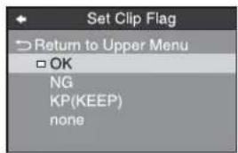
4 Select the clip flag that you want to set (OK/NG/KP(KEEP)), and then press the PUSH SET knob.
The clip flag is set for all selected clips, and the clip flag icon (see page 58) appears on thumbnails.
To clear clip flags
Carry out steps 1 to 3, selecting a clip that has a flag set, and then select "none" in step 4.
Locking (write-protecting) clips
In a clip list screen, you can lock the selected clips so that they cannot be deleted or altered.
Locking prevents the following operations on clips.
- Deletion
- Changing the index picture
- Adding and deleting shot marks
- Setting and clearing clip flags
Notes
- Locked clips are deleted along with other clips when a media is formatted.
- Clips cannot be locked or unlocked when a media is write protected.
To lock clips
1 In a clip list screen, select the clips that you want to lock (multiple selections possible).
This step is not needed if you lock all clips.
2 Display the Clip Menu.
3 Select Lock Unlock Clips.
The Lock Unlock Clips screen appears.
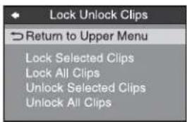
4 Select Lock Selected Clips or Lock All Clips, and then press the PUSH SET knob.
The clips selected in step 1 or all clips are locked. A lock icon (see page 58) appears on the thumbnail of the locked clips.
Tip
You can lock the selected clips by pressing the STOP button while holding down the SHIFT button in step 1.
To unlock clips
1 Execute the steps 1 to 3 in the previous section.
2 Select Unlock Selected Clips or Unlock All Clips, and then press the PUSH SET knob.
3 Select "OK", and then press the PUSH SET knob.
Tip
When you select a clip you want to unlock in the clip list screen and then press the STOP button while holding down the SHIFT button, a dialog appears asking you to confirm unlock. When you select "OK" and press the PUSH SET knob, the selected clip is unlocked. (To cancel unlock, select "CANCEL" and press the PUSH SET knob.)
Deleting clips
Notes
- Clips cannot be deleted when a media is write protected.
- Locked clips cannot be deleted.
1 In a clip list screen, select the clips that you want to delete (multiple selections possible).
This step is not needed if you delete all clips.
2 Display the Clip Menu.
3 Select Delete Clips.
The Delete Clips screen appears.

4 Select Delete Selected Clips or Delete All Clips, and then press the PUSH SET knob.
5 Select "OK", and then press the PUSH SET knob.
The clips selected in step 1 or all clips are deleted.
Tip
You can delete the selected clips simply and easily by pressing the RESET button while holding down the SHIFT button in step 1 and by carrying out step 5.
Copying clips
See "Copy operations" (page 53) for information about operations.
Setting the index picture frame
The clip thumbnail screen displays thumbnails as index pictures for clips. Normally the index picture is the first frame in a clip, but you can change it to any frame in the clip for a different index picture.
Note
You cannot set index pictures for EDLs.
1 In the basic operation screen or video monitor screen, play back the clip you want set the index picture frame.
2 Press the STOP button at the frame you want to be the index picture frame, to obtain a still frame display.
3 Display the page P5 OTHER of the function menu, and press the INDEX function button (F1).
A confirmation box appears asking you whether to set the frame of the still image as the index picture frame.
4 To set the current frame as the index picture frame, select "OK" and press the PUSH SET knob.
To set another frame as the index picture frame Select "CANCEL" and press the PUSH SET knob, turning the confirmation box off. Start again from step 1.
When you switch the display to the clip list screen, the newly set index picture is displayed as the thumbnail.
EDL Editing
What is EDL editing?
EDL editing is a function which allows you to select material (clips) from the material recorded on media and perform cut editing. You can do this by operating on this unit only.
- EDL editing is a convenient way to perform cut editing in the field and in other offline situations.
- In EDL editing you create an EDL (editing list). Since the material itself is not affected, you can repeat this any number of times.
- You can play back the edit list created on this unit.
- Using the EDL editing function, you can easily perform functions with this unit, such as add entire clips, add partial clips, and delete sub clips.
- Changing the sequence of sub clips and modifying the IN/OUT points are not supported.
- An EDL (editing list) can be used on XPRI and other full-feature nonlinear editing systems.
Note
EDLs in which clips recorded in the XAVC Long 50/35/25 Mbps recording format coexist with clips recorded in other formats cannot be created.
Clips
Material recorded on media with this unit is managed in units called "clips". A clip contains the material from a recording start point to a recording end point. Clips have numbers beginning with C, for example C0001.
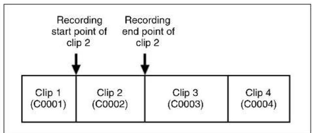
flowchart
graph TD
    A["Recording start point of clip 2"] --> B["Clip 1 (C0001)"]
    C["Recording end point of clip 2"] --> D["Clip 2 (C0002)"]
    E["Recording end point of clip 2"] --> F["Clip 3 (C0003)"]
    G["Recording end point of clip 2"] --> H["Clip 4 (C0004)"]
EDLs
You can use the EDL editing function to select clips from the clips saved on media and create a cut edit list called an "EDL".
EDLs have numbers beginning with E, for example E0001. Up to 99 clip lists can be saved on an SxS memory card.
Sub clips (clips in EDLs)
Clips (or parts of clips) that have been added to an EDL are called "sub clips". Sub clips are virtual editing data that specify ranges in the original clips. You can use them without modifying the original data.
The following figure illustrates the relation between clips and sub clips.
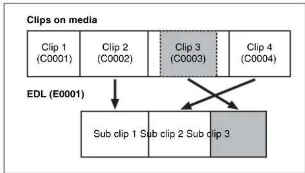
flowchart
graph TD
    A["Clip 1 (C0001)"] --> D["Sub clip 1 Sub clip 2 Sub clip 3"]
    B["Clip 2 (C0002)"] --> D
    C["Clip 3 (C0003)"] --> D
    E["Clip 4 (C0004)"] --> D
    F["EDL (E0001)"] --> D
    D --> G["Crossed to Sub clip 1 Sub clip 2 Sub clip 3"]
In the above example, the whole of clip 2 has been added as sub clip 1, and the whole of clip 4 has been added as sub clip 2.
Sub clip 3 is part of clip 3. Therefore, when EDL E0001 is played back, clip 4 is played after clip 2, and then the part of clip 3 shown in gray color is played.
EDL editing (current EDL)
To edit an EDL on media, you must first select the target EDL for editing. Existing EDLs and newly created EDLs can be selected. The target EDL for editing is called the "current EDL".
EDLs are automatically saved to media when they are created and modified.
The current EDL icon is displayed in the status indicator area in the clip list display when the current EDL is selected.
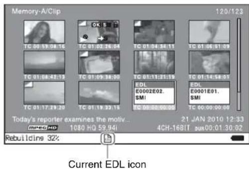
EDL playback
Clips and EDLs are saved together on media. To play an EDL, insert the media into the unit, load the EDL that you want to play, and press the PLAY button. Clips are played according to the data in the EDL.
Creating and editing EDLs
The following table lists the steps in the creation and editing of EDLs with the EDL editing function. To create an EDL, you always need to carry out the steps inside the heavy lines. Other steps can be carried out as required.
| 1 | Create EDLs: Use the CREATE NEW EDL command to create an EDL containing the selected clips. |
| 2 | Add sub clips: Use the ADD TO CURT.EDL command to add the clips you want to use to an EDL. You can add up to 300 sub clips to one EDL. |
| 3 | Delete sub clips: Use the REMOVE command to delete specified sub clips from an EDL. |
| 4 | Play the EDL: Use the PLAY button and other playback controls to play the current EDL and check its contents. |
To create an EDL
You can select multiple clips on the clip list screens and then create a new EDL. You can also create a new EDL by assigning an IN point/OUT point on the video monitor screen.
Creating an EDL in the clip list screens
See page 55 for information about screen operations.
1 In a clip list screen, select the clips that you want to become sub clips (multiple selections possible).
2 Press and hold the SHIFT button and then press the PUSH SET knob or display the P1 EDL page of the Clip F menu and press the CREATE NEW EDL button (F3).
The EDL creation starts.
The name for the created EDL appears when the creation finishes. The created EDL becomes the current EDL.
3 Select "OK", and then press the PUSH SET knob.
Creating an EDL in the video monitor screen
You can create an EDL while checking the video on the video monitor screen by specifying the range to use as a sub clip. You can perform this operation during recording, playback (including when stopped), and searching. During recording, the currently recording clip cannot be used as a sub clip to create a new EDL, but IN/OUT points can still be set.
1 In the video monitor screen, cue the frame you want to specify for the IN point.
2 Press and hold the ←/IN button, and then press the PUSH SET knob.
The IN/OUT setting window appears on the bottom right.
The time code for the IN point is displayed in the IN/OUT setting window, and the IN indicator is lit.
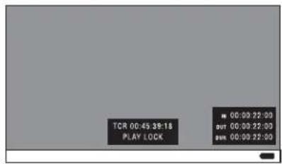
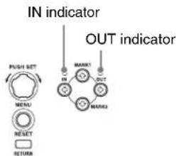
3 Cue the frame you want to specify for the OUT point.
4 Press and hold the ➤/OUT button, and then press the PUSH SET knob.
The IN/OUT setting window appears on the bottom right.
The time codes for the OUT point and duration (DUR) are displayed in the IN/OUT setting window, and the OUT indicator is lit.
5 Press the STOP button.
6 Press the PAGE/HOME button to display the function menu, and press the CREATE NEW EDL button (F3).
The EDL creation starts.
The name for the created EDL appears when the creation finishes. The created EDL becomes the current EDL.
When the current EDL is specified, the current EDL icon appears in the status display area.
7 Select "OK", and then press the PUSH SET knob.
To add sub clips to an existing EDL
Sub clips can be added from the clip list display screens or the video monitor screen. The added clips are inserted at the end of the EDL.
Sub clips are added to the current EDL. Consequently, an EDL must be selected as the current EDL in order to perform this operation. An EDL is made the current EDL automatically after it is created, as explained in "To create an EDL" above, allowing sub clips to be added immediately to the EDL. You can determine whether the current EDL is selected or not by checking whether the current EDL icon is displayed or not in the status display
area. If the current EDL is not specified, you must select an existing EDL as the current EDL using the following procedure before you can add sub clips.
1 Select an EDL on a clip list display screen.
2 Display the P1 EDL page of the Clip F menu and press the SET CURT.EDL button (F1).
The selected EDL becomes the current EDL. When the current EDL is specified, the current EDL icon appears in the status display area.
Adding in clip list screens
See page 55 for information about screen operations.
1 On a clip list screen, select the clip to add as a sub clip (multiple selections possible).
2 Press and hold the SHIFT button and press the PUSH SET knob or display the P1 EDL page of the Clip F menu then press the ADD TO CURT.EDL button (F4).
The sub clip addition starts. When addition is finished, the screen displayed during execution disappears and returns to the clip list screen. Adding a sub clip simultaneously saves the EDL.
The clip is added to the end of the current EDL. The current EDL remains selected.
Adding in the video monitor screen
When checking the image on the video monitor screen, a range to use as a sub clip can be specified and added to the current EDL. This operation is supported during playback (including when stopped) and when searching. During recording, the currently recording clip cannot be added as a sub clip to the current EDL, but IN/OUT points can still be set.
1 On the video monitor screen, cue the frame you want to specify for the IN point.
2 Press and hold the ←/IN button, and then press the PUSH SET knob.
The IN/OUT setting window appears on the bottom right of the display.
The timecode for the IN point is displayed in the IN/OUT setting window, and the IN indicator is lit.
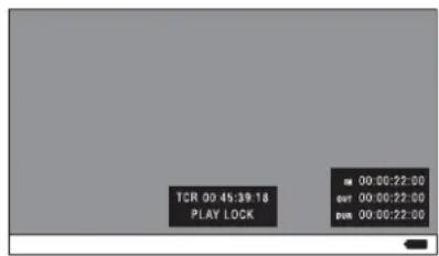
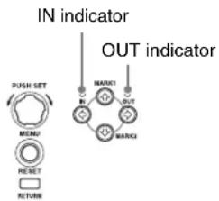
3 Cue the frame you want to specify for the OUT point.
4 Press and hold the ➤/OUT button, and then press the PUSH SET knob.
The IN/OUT setting window appears on the bottom right of the display.
The timecodes for the OUT point and duration (DUR) are displayed in the IN/OUT setting window, and the OUT indicator is lit.
5 Display the function menu, and then press the ADD TO CURT.EDL button (F4).
The sub clip addition starts. When addition is finished, the screen displayed during execution disappears and returns to the clip list screen. Adding a sub clip simultaneously saves the EDL.
The clip is added to the end of the current EDL. The current EDL remains selected.
To delete sub clips
This operation is performed on the chapter thumbnail screen.
1 In the chapter thumbnail screen, select the thumbnails for the sub clips you want to delete (multiple selections possible).
2 Press the PAGE/HOME button to display the function menu, and press the REMOVE function button (F4).
A confirmation message appears asking whether to execute the delete operation.
3 Select "OK", and then press the PUSH SET knob. To abort, select "Cancel".
To play an EDL
1 In the chapter thumbnail screen, select the thumbnail for the sub clip you want to start playing.
To start playing from the first frame of the EDL Select the thumbnail for the first sub clip.
2 Press the PLAY button.
To release the current EDL
This operation clears the current EDL from the memory in this unit. This operation is performed on clip list screens. Releasing the current EDL after editing is finished prevents changes to the settings due to incorrect operation.
Note
The current EDL is also released when the target media is changed using the SLOT SELECT button.
1 In a clip list screen, display the P1 EDL page of the Clip F menu.
2 Press the RELEASE CURT.EDL function button (F2).
A confirmation message appears asking you whether to execute the release operation.
3 Select "OK", and then press the PUSH SET knob.
The current EDL is released and the current EDL icon is removed from the status display area.
To reference the current EDL
Referencing the current EDL displays the chapter thumbnail screen for the current EDL. This operation is performed on clip list screens.
1 Display the P1 EDL page of the Clip F menu.
2 Press the GOTO CURT.EDL function button (F6).
The currently specified current EDL is displayed on the chapter thumbnail screen.
1 In a clip list screen, press the MENU button to display the Clip menu.
2 Select "Media Properties", and then press the PUSH SET knob.
The media properties screen for the selected media appears.
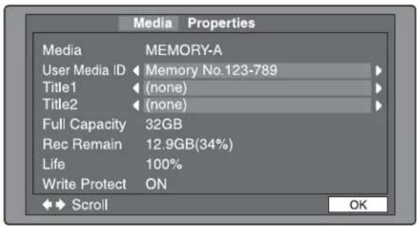
Media: MEMORY-A or MEMORY-B
User Media ID: User media ID
Title1: Title 1
Title2: Title 2
Full Capacity: Total capacity
Rec Remain: Remaining capacity for recording
Life: Memory write lifespan (0 to 100%) ^1
Write Protect: Status of the write protect switch
1) Displayed only for SxS memory cards that support this function.
To display hidden text
For items displaying ◀ or ▶, press the ◀/IN or ➤/OUT button to scroll the text by one character at a time. Pressing the ♦/MARK1 or ♦/MARK2 button displays the first character or last character, respectively.
To return to the previous screen
Press the PUSH SET knob.
You can format recorded SxS memory cards.
Notes
- SxS memory cards formatted by this unit are formatted in UDF or exFAT. Formatting in FAT is not supported.
- This unit does not support memory cards exceeding 256 GB, excluding SDXC cards.
1 Insert the SxS memory card you want to format into the memory card slot.
2 Press the SLOT SELECT button.
When two SxS memory cards are inserted
Press the SLOT SELECT button and select the card (A/B) to be formatted.
3 Switch the display to a clip list screen.
4 Press the MENU button to display the Clip Menu.
5 Select "Format Media(UDF)" or "Format Media(exFAT)", and then press the PUSH SET knob.
A confirmation message appears asking you whether to execute the format operation.
Notes
- SxS memory cards formatted by this unit are formatted in UDF or exFAT. Formatting in FAT is not supported.
- Proxy AV data will not be recorded to an SxS memory card formatted in exFAT.
6 To execute formatting, select "OK", and then press the PUSH SET knob.
The formatting starts, and the “Format Executing…” message appears.
Select "CANCEL", and then press the PUSH SET knob.
When the formatting is completed, the message "Format was successful." appears.
Remove the SxS memory card and insert another SxS memory card into the memory card slot. When the confirmation dialog appears asking if you want to execute formatting, execute step 6 once more.
7 When formatting is completed, select "Exit", and then press the PUSH SET knob.
Notes
- An SxS memory card can be formatted during recording in relay recording mode only.
- Only the memory card in the slot that is not currently recording can be the target for formatting.
1 During recording, press the THUMBNAIL button.
2 Press the SLOT SELECT button.
Select the memory card slot that is not currently recording to display the clip list screen.
3 Press the MENU button to display the Clip Menu.
4 Select "Format Media(UDF)" or "Format Media(exFAT)", and then press the PUSH SET knob.
A confirmation message appears asking you whether to execute the format operation.
Note
The memory card can only be formatted with the same file system as the currently recording memory card.
5 To execute formatting, select "OK", and then press the PUSH SET knob.
The formatting starts, and the “Format Executing…” message appears.
Select “CANCEL”, and then press the PUSH SET knob.
When the formatting is completed, the message "Format was successful." appears.
6 Press the THUMBNAIL button.
The clip list screen disappears, and the display returns to the previous screen.
File Operations
Chapter
6
Overview
A remote computer can be connected to this unit and used to operate on recorded data which has been saved in data files, such as video and audio data files.
To perform file operations, use either of the following methods to interconnect this unit and a computer.
- Make FTP connections (see page 71).
- Make CIFS connections (see page 75).
Notes
- SxS memory cards inserted in this unit cannot be displayed or operated on the unit while there is a remote connection using FTP/CIFS from an external device.
- When SxS memory card restoration is necessary after FTP or CIFS connections are undone, the restoration is automatically executed on this unit.
Directory structure
The following figure shows an example of the directory structure visible to the computer connected to this unit.
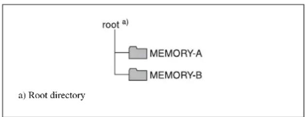
flowchart
graph TD
    A["root a)"] --> B["MEMORY-A"]
    A --> C["MEMORY-B"]
On the computer, each SxS memory card in slot A or B by accessing the MEMORY-A or MEMORY-B directory.
File operation restrictions
The following operations are possible on files stored in each directory.
- Read
- Write
- Rename
- Create
- Delete
"Read" and "write" are defined as follows.
Read: Read data sequentially from the desired position to the end of the file.
Write: Write data sequentially from the start to the end of the file.
FTPS protocol support
The unit supports the FTP and FTPS protocols (software version 1.1x and later).
The FTPS protocol is recommended when using the unit in an insecure network environment.
FTP File Operations
File operations between this unit and a remote computer can be carried out by the File Transfer Protocol (called FTP below).
Preparations
1 Connect the network connectors of this unit and a remote computer with a network cable (see connections illustration on page 25). Or connect this unit to the network to which the remote computer is connected (see connections illustration on page 26).
2 Set the IP address and other network setting items for this unit. ^1)
For details, refer to maintenance menu item M51 (page 97).
If network settings have already been made
Check the IP address of this unit.
For details, refer to maintenance menu item M51 (page 97).
1) This unit is able to acquire an IP address automatically from a DHCP server. It also supports an Auto-IP function to assign an IP address automatically when access from this unit to the DHCP server times out. You can check DHCP settings and the assigned IP address with maintenance menu.
To connect a computer running Windows 8/Windows 10
Disable the Internet Protocol Version 6 (TCP/IPv6).
Windows 8: (1) Open “View network status and tasks” > “Change adapter settings” > “Ethernet” in the control panel. (2) Display “Ethernet Properties”, uncheck “Internet Protocol Version 6 (TCP/IPv6)”, and then click the OK button.
Windows 10: (1) Open "Control Panel." (2) Select "Network and Internet" > "Network and Sharing Center" > "Change adapter settings". (3) Right-click the network connection of the computer and select "Properties". (4) Uncheck "Internet Protocol Version 6 (TCP/IPv6)", and then click the OK button.
3 Set the remote control switch to "NET" (see page 11).
Making FTP connections
FTP connections between this unit and a remote computer can be made with either of the following.
• The command prompt
- FTP client software
This section explains how to use the command prompt. For more information about using FTP client software, refer to the documentation of the FTP client software on your system.
To log in
1 Put the unit into the following state.
- Recording, playback, search and other SxS memory card operations (see page 45): Stopped
- Display screen: Other than the clip list screen (see page 55)
2 Start the command prompt.
3 Enter "ftp ", and press the Enter key. ( refers to a space.)
For example, if the IP address of this unit is set to "192.168.001.010", enter "ftp 192.168.1.10".
Refer to the Windows help for more information about the FTP command.
If the connection succeeds, you are prompted to enter a user name.
4 Enter the user name "admin" and press the Enter key.
When the user name is verified, you are prompted to enter a password.
5 Enter the password and press the Enter key.
The password is set during initial setup. For details, see "Initial Setup" (page 24).
The login is complete when the password is verified.
See page 72 for the FTP protocol commands supported by this unit.
If the connection times out
This unit terminates FTP connections if no command is received within 90 seconds of the last command. If this occurs, log out (see the next section) and repeat steps 2 to 4.
Note
If you power this unit off during an FTP connection, the data transferred thus far is discarded.
To log out
To log out after finishing file operations, enter "QUIT" at the command prompt and press the Enter key.
Command list
The FTP protocol commands supported by this unit include standard commands (see the next section) and extended commands (see page 74).
Notes
• To execute FTP commands, you must install application software with FTP function on your computer.
• The commands supported by application software vary.
- An FTP client that supports UTF-8 is required to use Unicode characters other than ASCII characters.
Command prompt FTP commands do not support UTF-8.
Standard commands
In the command syntax, means a space, entered by pressing the space bar, and means a new line, entered by pressing the Enter key.
USER
Send this command to begin the login process.
Command syntax: USER
Input example: USER admin
PASS
After sending the USER command, send this command to complete the login process.
Command syntax: PASS
Input example: PASS password
QUIT
Terminates the FTP connection. If a file is being transferred, terminates after completion of the transfer.
Command syntax: QUIT
PORT
Specifies the IP address and port to which this unit should connect for the next file transfer (for data transfer from this unit).
Command syntax: PORT
- h1 (most significant byte) to h4 (least significant byte): IP address
- p1 (most significant byte), p2 (least significant byte): Port number
Input example: PORT 10,0,0,1,242,48
(IP address: 10.0.0.1, Port number: 62000)
PASV
This command requests this unit to "listen" on a data port (which is not its default data port). (It puts this unit into passive mode, waiting for the remote computer to make a data connection.)
Command syntax: PASV
TYPE
Specifies the type of data to be transferred.
Command syntax: TYPE <type-code (options delimited by )
can be any of the following. However, for XDCAM, data is always transferred as "I", regardless of the type-code specification.
• A: ASCII
- N: Non-print
- T: Telnet format
- C: ASA Carriage Control
• E: EBCDIC
- N: Non-print
- T: Telnet format
- C: ASA Carriage Control
• I: IMAGE (Binary) (default)
• L: LOCAL BYTE
- SIZE: byte size
Input example: TYPE I
STRU
Specifies the data structure.
Command syntax: STRU
can be any of the following. However, for XDCAM, the structure is always "F", regardless of the structure-code specification.
• F: File structure (default)
• R: Record structure
- P: Page structure
Input example: STRU F
MODE
Specifies the transfer mode.
Command syntax: MODE
can be any of the following. However, for XDCAM, the mode is always "S", regardless of the mode-code specification.
• S: Stream mode (default)
• B : Block mode
• C: Compressed mode
Input example: MODE S
LIST
Sends a list of files from this unit to the remote computer.
Command syntax: LIST
can be any of the following.
- -a: Also display file names that begin with “.”
- -F: Append "/" to directory names.
The following data is transferred, depending on whether specifies a directory or file.
- Directory specified: A list of the files in the specified directory
- File specified: Information about the specified file
- No specification: A list of the files in the current directory
The wildcard characters “*” (any string) and “?” (any character) may be used in .
Input example 1: LIST-a Clip
Input example 2: LIST Clip/*.MXF
NLST
Sends a list of file names from this unit to the remote computer, with no other information.
Command syntax: NLST
The following options may be specified when no pathname is specified.
- -a: Also display file names that begin with “.”
- -I: Display information other than file name (gives the same result as the LIST command).
- -F: Append "/" to directory names.
The following data is transferred, depending on whether specifies a directory or file.
- Directory specified: A list of the file names only in the specified directory
- No specification: A list of the file names only in the current directory.
The wildcard characters “*” (any string) and “?” (any character) may be used in .
Input example 1: NLST-I
Input example 2: NLST Clip/*.MXF
RETR
Begins transfer of a copy of a file in the specified path on this unit to the current directory on the remote computer.
Command syntax: RETR
Input example: RETR Clip/C0001.MXF
STOR
Begins transfer of a copy of a file in the specified path on the remote computer to the current directory on this unit.
Command syntax: STOR
Input example: STOR Edit/E0001E01.SMI
RNFR
RNTO
Rename a file.
Specify the file to be renamed with the RNFR command, and specify the new name with the RNTO command. (Always follow a RNFR command with a RNTO command.)
For details, see "File operation restrictions" (page 70).
Command syntax: RNFR
RNTO
Input example: RNFR General/info.txt
RNTO General/clip_info.txt
DELE
Deletes the specified file on this unit.
Note
Depending on the directory and file type, deletion may not be possible.
For details, see "File operation restrictions" (page 70).
Command syntax: DELE
Input example: DELE Clip/C0099.MXF
STAT
Sends information about properties of the specified file, or about data transfer status, from this unit to the remote computer.
Command syntax: STAT
The following data is transferred, depending on whether a file is specified with .
- File specified: The properties of the specified file
- No specification: 1)
Input example: STAT Clip/C0001.MXF
1) Not supported in this version; always size 0.
SYST
Displays the system name of this unit.
Command syntax: SYST
HELP
Displays a list of the commands supported by this unit, or an explanation of the specified command.
Command syntax: HELP
The following data is transferred, depending on whether a command name is specified with .
- Command name specified: Explanation of the specified command.
- No specification: Command list
Input example: HELP RETR
NOOP
Does nothing except return a response. (Used to check whether this unit is running.)
Command syntax: NOOP
PWD
Displays the current directory (“/” if the directory is the root directory).
Command syntax: PWD
CWD
Changes the current directory (moves from the current directory to another directory).
Command syntax: CWD
Moves to a directory as follows, depending on whether a directory is specified with .
- Directory specified: To the specified directory
- No specification: To the root directory
Input example: CWD General
CDUP
Moves one level up in the directory structure (makes the parent of the current directory be the current directory).
Command syntax: CDUP
MKD
Creates a new directory.
Command syntax: MKD
RMD
Deletes a directory.
Command syntax: RMD
Note
Some limitations apply to the deletion of directories.
For details, see "File operation restrictions" (page 70).
Extended commands
In the Command syntax, means a space, entered by pressing the space bar, and means a new line, entered by pressing the Enter key.
SITE DF
Displays the remaining space of the applicable media in the current directory.
Command syntax: SITE DF
SITE MEID
Displays the ID of the applicable media in the current directory.
Command syntax: SITE MEID
SITE CHMOD
Locks and unlocks clips. Also sets permissions for directories and files.
Command syntax: SITE CHMOD
Specify one of the following values in , according to the specification in .
- When a clip is specified in
- When a directory is specified in
- 555: Forbid writing to the directory.
- 777: Allow writing to the directory.
- When a file is specified in
- 444: Forbid writing to and execution of the file.
- 555: Forbid writing to the file, but allow execution.
- 666: Allow writing to the file, but forbid execution.
- 777: Allow writing to and execution of the file.
Input example: SITE CHMOD 444 Clip/C0001.MXF (Lock clip C0001.MXF)
CIFS File Operations
You can perform file operations using the Common Internet File System (CIFS) between this unit and the computer.
Preparations
See “Preparations” under “FTP File Operations” (page 71).
Making CIFS connections
CIFS connections between this unit and a Windows computer can be made with either of the following.
- Use Windows Explorer to map this unit as a network drive
- Refer to this unit directly from Windows Explorer
The following describes the procedure for using Windows Explorer to map this unit as a network drive. ^1)
1 Start Windows Explorer.
2 In the Tools menu, select "Map Network Drive...". The Map Network Drive dialog appears.
3 Enter “\\xdcam\" in the “Folder” field.
For example, if the IP address of this unit is set to "192.168.001.010", enter “\192.168.1.10\xdcam”.
4 Click on "Connect using a different name". The Connect As... dialog appears.
5 Enter the user name "admin" and the password, and click OK.
The password is set during initial setup. For details, see “Initial Setup” (page 24).
6 Click Finish.
The network drive allocation is complete when the password is verified.
To break the connections
In Windows Explorer, select the network drive and right-click it, then click "Disconnect".
1) Operations may differ depending on the Windows version you are using.
The settings for this unit use the following menus.
The setup menu system of this unit comprises the basic setup menu and extended setup menu.
For details, see “Basic Operations of the Function Menu” (page 37).
For details, see "Clip Menu" (page 59).
Maintenance menu
This provides audio control, and network and setup menu settings, and also shows version information.
For details, refer to "Maintenance Menu" (page 95).
The setup menu system of this unit comprises the basic setup menu and extended setup menu.
This menu is used to make settings relating, for example, to the following.
• the operating hours meter
- the text information superimposed on the video output to the monitor
- the menu banks for retaining menu settings
This menu is used to make a wide range of settings relating to the functions of this unit, for example, the control panel functions, video and audio control, and digital data processing.
The basic menu comprises the following groups of items.
| Item group Function Refer to | |
| Items H01 and H11 | Display of the total number of hours the unit has been powered on, and other information collected by the operating hours meter | page 102 |
| Items 001 to 099 | Settings relating to the superimposed text information, switching between 59.94i, 59.94P, 29.97P, 50i, 50P and 25P. | page 77 |
| Items B01 to B20 | Settings relating to the menu banks for saving menu settings | page 79 |
The extended menu is displayed when maintenance menu item M40: EXTENDED MENU is set to ENABLE.
The extended menu comprises the following groups of items.
| Item group Function Refer to | |
| Items100 to 199 | Settings relating to control panels | page 83 |
| Items200 to 299 | Settings relating to the remote control interface | page 84 |
| Items300 to 399 | Settings relating to editing operations | page 85 |
| Items600 to 649 | Settings relating to the timecode generator | page 85 |
| Item group Function Refer to | |
| Items650 to 699 | Settings relating to the metadata | page 86 |
| Items700 to 799 | Settings relating to video control | page 87 |
| Items800 to 899 | Settings relating to audio control | page 89 |
| Items900 to 999 | Settings relating to digital processing | page 90 |
The basic menu items (excluding the items related to the operating hours meter) are listed in the following table.
- The values in the “Settings” column are the values that appear in settings screens. The values in brackets [ ] are the value shown in menu screens (when they differ from the values shown in settings screens).
- The underlined values are the factory defaults.
| Item number | Item name Settings | |
| 002 CHARACTER H-POSITION Adjust the hor | horizontal screen position (as a hexadecimal value) of the textinformation output from the COMPOSITE OUTPUT 2 (SUPER), SDSDI OUTPUT 2 (SUPER), HDSDI OUTPUT 2 (SUPER), or HDMI OUT connector for superimposed display on the monitor. The hexadecimal value 00 is for the far left of the screen. Increasing the value moves the position of the characters to the right.00 to to 28 (When the number of system lines is 1080 and the system frequency is 59.94i, 29.97P, 50i, 25P, or 23.98P)00 to to 28 (When the number of system lines is 720 and the system frequency is 59.94P or 50P)Set this item by adjusting to the required position while viewing the monitor. |
| 003 CHARACTER V-POSITION Adjust the vert | rical screen position (as a hexadecimal value) of the textinformation output from the COMPOSITE OUTPUT 2 (SUPER), SDSDI OUTPUT 2 (SUPER), HDSDI OUTPUT 2 (SUPER), or HDMI OUT connector for superimposed display on the monitor. The hexadecimal value 00 is for the top of the screen. Increasing the value lowers the position of the characters.00 to 2A to 32 (When the number of system lines is 1080 and the system frequency is 59.94i, 29.97P, 50i, 25P, or 23.98P)00 to 29 to 32 (When the number of system lines is 720 and the system frequency is 59.94P or 50P)Set this item by adjusting to the required position while viewing the monitor. |
| 005 DISPLAY | INFORMATION SELECT | Determine the kind of text information to be output from the COMPOSITE OUTPUT 2 (SUPER), SDSDI OUTPUT 2 (SUPER), HDSDI OUTPUT 2 (SUPER), or HDMI OUT connector.time data & status [T&sta]: Time data and the units status.time data & UB [T&UB]: Time data and user bits data. (When “UB” (user bits data) is selected with CNTR SEL on the HOME page of the function menu, the “user bits data” and “time data” arranged in that order are displayed.)time data & CNT [T&CNT]: Time data and counter count. (When “COUNTER” is selected with CNTR SEL on the HOME page of the function menu, the counter count and time data arranged in that order are displayed.)time data & time data [T&T]: Time data and timecode (TC or VITC)time data only [time]: Time data only |

| Item number | Item name | Settings |
| 006 LOCAL FUNCTION ENABLE Determine which recording and playback control buttons on the front panel are enabled when this unit is controlled from external equipment.all disable [dis]: All buttons and switches are disabled.stop & eject [st&e]: Only the STOP button can operate.all enable [ena]: All buttons and switches are enabled. |
| 009 CHARACTER TYPE Determine the type of characters such as timecode output from the COMPOSITE OUTPUT 2 (SUPER), SDSDI OUTPUT 2 (SUPER), HDSDI OUTPUT 2 (SUPER), or HDMI OUT connector for superimposed display on the monitor.white: White letters on a black backgroundblack: Black letters on a white backgroundwhite/outline [W/out]: White letters with black outlineblack/outline [B/out]: Black letters with white outline |
| 011 CHARACTER V-SIZE Determine the vertical size of characters such as timecode output from the COMPOSITE OUTPUT 2 (SUPER), SDSDI OUTPUT 2 (SUPER), HDSDI OUTPUT 2 (SUPER), or HDMI OUT connector for superimposed display on the monitor.×1: Standard size×2: 2 times standard sizeSet this item by selecting the required size while viewing the monitor. |
| 012 CONDITION DISPLAY ON VIDEO MONITOR | Specify whether to display playback condition marks on an external monitor (output from COMPOSITE OUTPUT 2 (SUPER), SDSDI OUTPUT 2 (SUPER), HDSDI OUTPUT 2 (SUPER), HDMI OUT connectors).disable [dis]: Do not display.enable [ena]: Display. |
| 013 SYSTEM FREQUENCY SELECT MENU | Specify whether to enable switching the system frequencies.off: Do not enable switching the system frequencies.on: Enable switching the system frequencies.You can switch between the following frequencies.1080/59.94i, 50i, 29.97P, 25P, 23.98P, 720/59.94P, 50PFor details about switching the system frequencies, see page 33.NoteSettings for both basic and extended menu items are saved separately for different system frequencies.• 1080 59.94i/29.97P• 1080 50i/25P• 1080 23.98P• 720 59.94P• 7 2 0 5 0 PTherefore, when you switch system frequencies, all menu items are reset to the current settings for the new mode. (They are different from the setting for the previous mode.) |
| 027 SD CHARACTER ACTER Specify whether to superimpose text information on the SD video signal. |
|
|
|
|
|
|
|
|
|
|
|
|
|
|
|
|
|
|
|
|
|
|
|
|
|
|
|
|
|
|
|
|
|
|
| Item number | Item name Settings | |
| 028 HD CHAR | ACTER Specify whether to superimpose text information on the HD video signal. |
| Sub-item | |
| 1 HD-SDI2 Specify whether to superimpose text information on the video signal output from the HDSDI OUTPUT 2 (SUPER) connector.off: Do not superimpose.on: Superimpose. |
| 2 HDMI Specify whether to superimpose text information on the video signal output from the HDMI OUT connector when the HDMI output is the same with the SDI output.off: Do not superimpose.on: Superimpose. |
| 029 STORED | OWNERSHIP Specify whether to enable changing UMID ownership information settings (COUNTRY, ORGANIZATION and USER).off: Do not enable.on: Enable.See "Using UMID Data" (page 114) for more information about UMID. |
| 031 RECORDING FORMAT Set the recording format.AI422: XAVC IntraAL50M: XAVC Long 50Mbpsb)AL35M: XAVC Long 35Mbpsb)AL25M: XAVC Long 25Mbpsc)HD422: HD422HD420 HQ [420HQ]: HD420 HQHD420 HQ1920 [HQ192]: HD420 HQ1920b)DVCAM: DVCAMA) |
| 033 BATTERY | END VOLTAGE Sets the voltage to shut down the unit in the battery operation. The battery near end indicator flashes at +0.7 V of the set voltage.10.5V to 13.5V: 10.5 V to 13.5 V in 0.5 V unit. |
| 036 FILE NAMING Set the clip name to be assigned to a clip to record. |
|
|
|
|
|
|
|
|
|
|
|
|
|
|
|
|
|
|
|
|
|
|
|
|
|
|
|
|
|
|
|
|
|
|
| Item number | Item name Settings | |
| B20 RESET | SETUP MENU Set to “on” to return | the settings of the current menu to the factory default settings. |
a) Not displayed when the unit is in 23.98P mode.
b) Not displayed when the unit is in 59.94P/50P mode.
c) Not displayed when the unit is in 29.97P/25P/23.98P/59.94P/50P mode.
Setup menus are displayed on the display or on a monitor connected to the HDMI OUT connector.
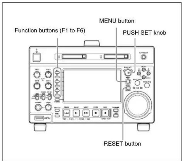
To display a setup menu, press the MENU button. The currently selected menu item is displayed in reverse video.
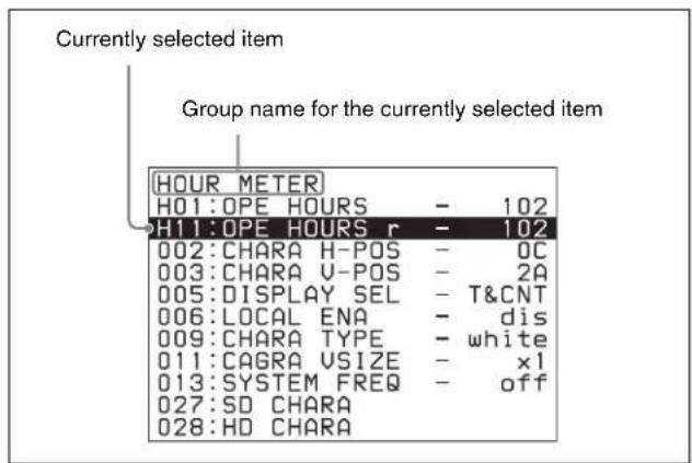
Use the following buttons to change setup menu settings.
| Menu control buttons | Functions |
| MENU button Disp | ays and hides the setup and user interface menus. |
| PUSH SET knob • | When turned clockwise or counterclockwise, moves the reverse video to select the item to change.When turned clockwise or counterclockwise, changes a menu item setting.When pressed, answers “Yes” to a question. |
| Function buttons F1 to F6(The function to be displayed varies depending on the situations.) | RETURN: Goes up one level.SELECT: Selects an item.UP: Skips back 100 or 50 items in the list of menu items.DOWN: Skips forward 100 or 50 items in the list of menu items.SAVE: Saves a new setting to memory.EXIT: Exits the current menu.-: Changes a setting.+: Changes a setting. |
| RESET button • | Returns the current setting to the factory default.Answers “No” to a question. |
Proceed as follows to change the settings of menu items.
1 Use the PUSH SET knob to select the required item.
Example: Screen display when item 005 DISPLAY SEL is selected
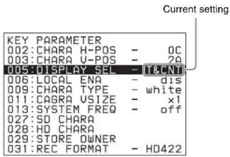
2 Press the PUSH SET knob or the SELECT function button (F2).
This displays the setting screen for the menu item selected in step 1.
Example: Setting screen display when item 005
DISPLAY INFORMATION SELECT is selected
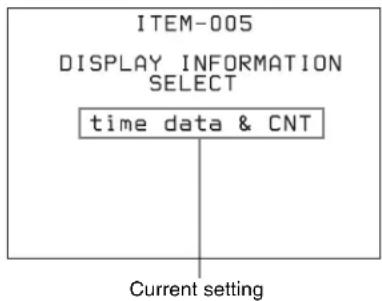
3 Use the PUSH SET knob or the +/- function button (F3 or F4) to change the setting.
Turning the PUSH SET knob while holding down the SHIFT button increases the increment of adjustment.
4 To change other settings, press the PUSH SET knob or the RETURN function button (F1) to return to the previous screen, then repeat steps 1 to 3.
5 When you have completed the settings, press the SAVE function button (F5).
The message “NOW SAVING...” appears on the video monitor screen, while the new settings are saved in memory. When the saving operation is completed, the video monitor screen returns to its normal indications.
Notes
- If you power off the unit before a save operation is completed, settings may be lost. Wait until the save is completed before powering off the unit.
- If, instead of pressing the SAVE function button (F5), you press the MENU button, the new settings are not saved. The message “ABORT!” appears on the video monitor screen for about 0.5 seconds, and the system exits the menus. To change more than one setting, be sure to press the SAVE function button (F5) after making the settings.
After changing menu settings, use the following procedure to return the settings to their factory default settings (setting initialization).
To return a particular setting to its factory default setting
In the screen that selects the setting of that item, press the RESET button.
For example, proceed as follows to return the 005 DISPLAY INFORMATION SELECT item to its default setting. This assumes that the setting has been changed from the factory default “time data & status” in step 3 of the procedure in “To change the settings of menu items” (page 80).
1 Press the RESET button.
“time data & status” (factory default setting) is selected.
2 Press the SAVE function button (F5).
The setting returned to its factory default is saved in memory as the current setting.
To return all settings to their factory default settings
1 Press the MENU button to display the setup menu.
2 Press the RESET button.
The message “INITIALIZE ALL ITEMS TO FACTORY PRESET VALUES?” appears, to confirm whether you wish to return all settings to their factory default settings.
3 Press the SAVE function button (F5).
The message “NOW SAVING...” appears on the video monitor screen, while the settings of all items are returned to their factory default settings. These factory default settings are saved in memory.
If you power off the unit while settings are being saved, settings may not be correctly returned to their factory default settings. Wait until the saving is completed before powering off the unit.
To abandon the resetting operation
Instead of pressing the SAVE function button (F5), press the RESET button.
The display returns to the top level of the setup menu, leaving the settings unchanged.
You can save menu settings in a menu bank. Menu settings saved in a menu bank can be recalled and used when needed.
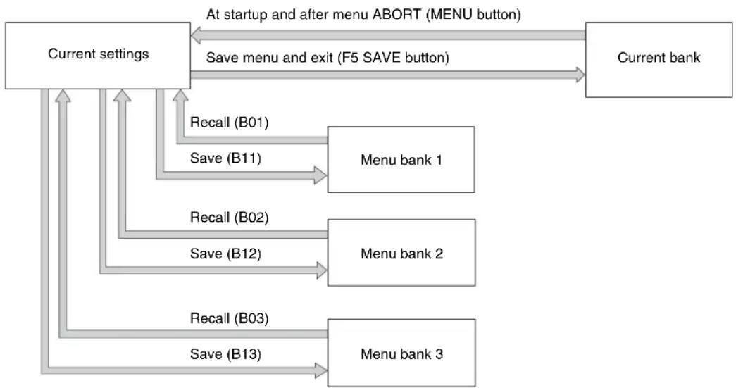
flowchart
graph TD
    A["Current settings"] -->|At startup and after menu ABORT (MENU button)| B(Current bank)
    A -->|Save menu and exit (F5 SAVE button)| B
    A -->|Recall (B01)| C["Menu bank 1"]
    A -->|Save (B11)| C
    A -->|Recall (B02)| D["Menu bank 2"]
    A -->|Save (B12)| D
    A -->|Recall (B03)| E["Menu bank 3"]
    A -->|Save (B13)| E
1 Select a menu item from B11 "SAVE SETUP BANK-1" to B13 "SAVE SETUP BANK-3" using the PUSH SET knob.
2 Press either the PUSH SET knob or the SELECT function (F2) button.
3 Change the setting to "on" using either the PUSH SET knob or + function (F4) button.
4 Press the SAVE function (F5) button.
“NOW SAVING…” is displayed, and the current settings are saved in the selected menu bank.
Note
Settings are not saved in the current bank when saving to a menu bank. To save changed settings in both a menu bank and the current bank, press the SAVE function (F5) button again after saving the settings in a menu bank to save the settings in the current bank.
1 Select a menu item from B01 "RECALL SETUP BANK-1" to B03 "RECALL SETUP BANK-3" using the PUSH SET knob.
2 Press either the PUSH SET knob or the SELECT function (F2) button.
3 Change the setting to "on" using either the PUSH SET knob or + function (F4) button.
4 Press the LOAD function (F5) button.
“NOW LOADING...” is displayed, and the settings saved in the selected menu bank are loaded into the current settings.
5 Press the SAVE function (F5) button.
“NOW SAVING...” is displayed, and the current settings are saved in the current bank. When saving is finished, the display returns to the operating screen.
The following tables show the items in the extended menu.
- The values in the “Settings” column are the values that appear in settings screens. The values in brackets [ ] are the value shown in menu screens (when they differ from the values shown in settings screens).
- The underlined values are the factory defaults.
Menu items in the 100s, relating to the control panels
| Item number | Item name Settings | |
| 101 SELECTION FOR SEARCH DIAL ENABLE | Select how the unit enters the shuttle, jog, or variable-speed mode.dial direct [dial]: Press the SHTL/JOG or VAR/JOG button or, except during recording/editing, turn the jog dial or shuttle dial.via search key [key]: Press the SHTL/JOG or VAR/JOG button. |
| 105 REFERENCE SYSTEM ALARM Select whether to display a warning when the reference video signal is not being supplied, or when it differs from this unit's system frequency.off: No warning.on: Flash the STOP button as a warning. |
| 108 AUTO EE SELECT If PB/EE is set to "EE" on the P5 OTHER page in the function menu, this selects the operation modes in which video/audio signal are handled as EE signals.stop/f.fwd/f.rev [S/F/R]: In stop, forward direction high-speed search, and reverse direction high-speed search modes.stop: In stop mode. |
| 114 AUDIO MONITOR OUTPUT LEVEL Select whether to control the level of the audio signal output from the AUDIO MONITOR OUTPUT R, L connectors with the LEVEL adjustment knob for the PHONES jack.variable [var]: Control.fixed: Do not control. |
| 121 FRAME PB MODE Select the variable-speed playback field/frame mode.auto: Field playbackframe: Frame playback.Compared to field playback, frame playback gives more detail during playback of still pictures. |
| 130 DISPLAY DIMMER CONTROL Set the brightness of the indication on the LCD.10%, 25%, 50%, 75%, 100% |
| 131 AUDIO VOLUME Select whether each of the CH-1/ALL CH, CH-2 to CH-4 adjustmentknobs on the control panel is effective to control the audio recording level and playback level on each channel or the CH-1/ALL CH adjustment knob alone functions as a master control to control the audio level on all channels together.each: Each of the CH-1/ALL CH, CH-2 to CH-4 adjustment knobs is effective to control each channel.all: The CH-1/ALL CH adjustment knob alone functions as a master control.When "all" is selected, the ALL CH indicator under the CH-1/ALL CH adjustment knob lights up. |
| 142 REPEAT MODE Set whether to set repeat playback mode.off: Do not set repeat playback mode.play: Set repeat playback mode.When "play" is selected, the icon indicating repeat playback mode appears in the basic operation screen. When "on" is selected also in setup menu item 154, the icon indicating both single clip playback mode and repeat playback mode appears in the basic operation screen.NoteOperate repeat playback from the front panel. Repeat playback is not available via the 9-pin VTR protocol or VDCP protocol. |
Menu items in the 100s, relating to the control panels
| Item number | Item name Settings | |
| 143 INDEX PICTURE POSITION Select the frame of | the clip to use as the thumbnail image (index picture) when recording.0sec to 10sec: Can be set in the range from 0 seconds (first frame of the clip) to 10 seconds, in units of 1 second. |
| 145 MODE KEY ENABLE DURING RECORDING | Set the mode buttons enabled during recording.all enable [ena]: All buttons are enabled.stop: Only the STOP button is enabled. |
| 151 GUI OPERATION Sets whether to disable switching to the clip list screens.enable [ena]: Enabledvia stop [stop]: Disabled (executable from stop mode only) |
| 154 SINGLE CLIP PLAY MODE Put the unit into single clip playback mode, or exit from single clip playback mode.off: Exits from single clip playback mode. (Puts the unit into continuous playback mode.)on: Puts the unit into single clip playback mode.When “on” is selected, the icon indicating single clip playback mode appears in the basic operation screen. When “play” is selected also in setup menu item 142, the icon indicating both single clip playback mode and repeat playback mode appears in the basic operation screen.NoteSelect the clip again to apply the setting. | | |
| 161 HDMI OUT SELECT Specify which signal to output from the HDMI OUT connector: the same signal as the SDI connector output, or the same signal as the SDI connector output and thumbnails view signal by automatically switching between them.auto: Output the same signal as the SDI connector output and thumbnails view signal by automatically switching between them.SDI [sdi]: Output the same signal as the SDI connector output. |
| 162 MXF PUT MODE Set whether to generate a metadata file when files are received via FTP/CIFS connection.normal: Do not generate metadata file when receiving files.PDW-like: Automatically generate metadata files (XML) when receiving clips (MXF) using “PUT”. Do not generate metadata files (XML) when receiving EDL (SMI) using “PUT”. |
Menu items in the 200s, relating to the remote control interface
| Item number | Item name Settings | |
| 208 PROTOCOL FOR REMOTE(9P) Select the protocol used with a REMOTE (9P) connector.VTR: Sony 9-pin VTR protocolVDCP: VDCP protocol |
| 214 REMOTE | INTERFACE When the remote control switch is set to REMOTE, select the device from which to remote-control this unit.9PIN: Device connected to the REMOTE(9P) connector.SDI: Device connected to the SD/HDSDI INPUT connector. |
| 257 NETWORK ENABLE Select the remote control switch positions which enable network connections.network [net]: Only when the switch is set to “NET”.network & remote(9PIN) [n&9P]: When the switch is set to “NET”, and when the switch is set to “REMOTE” and setup menu item 214 is set to “9PIN”. |
| 259 NETWORK INTERFACE Select network protocols to be enabled.FTP/CIFS [ftp]: Enable FTP and CIFS.NET-RMT [nrmt]: Enable NetAPI and WebAPI.ALL [all]: Enable all protocols. |
Menu items in the 300s, relating to editing operations
| Item number | Item name Settings | |
| 320 DIGITAL | AUDIO PB PROCESS ONEDIT POINT | Specify the handling of audio at edit points.cut:Carry out a cut (possibly resulting in audio discontinuities at the edit point).fade:Fade out and fade in. |
Menu items in the 600s, relating to the timecode and metadata
| Item number | Item name Settings | |
| 601 VITC POSITION | ITIONSEL-1a) | In 59.94i/59.94P/29.97P mode | Select the line into which to insert VITC signals (SD output)12H to 16H to 20H: Any line from line 12 through line 20.NotesYou can insert VITC signals in two places. To insert in two places, set both item 601 and item 602.In 59.94i/59.94P/29.97P mode (J), output of wide picture information is given priority if OUTPUT in setup menu item 731 is set to “auto” and the VITC insertion line is set to line 16.In 59.94i/59.94P/29.97P mode (UC), output of wide picture information is given priority if OUTPUT in setup menu item 731 is set to “auto” and the VITC insertion line is set to line 20. |
| In 50i/50P/25Pmode | Select the line into which to insert VITC signals (SD output)9H to 19H to 22H: Any line from line 9 through line 22.NoteYou can insert VITC signals in two places. To insert in two places, set both item 601 and item 602. |
| 602 VITC POSITION | ITIONSEL-2a) | In 59.94i/59.94P/29.97P mode | Select the line into which to insert VITC signals (SD output)12H to 18H to 20H: Any line from line 12 through line 20.NotesYou can insert VITC signals in two places. To insert in two places, set both item 601 and item 602.In 59.94i/59.94P/29.97P mode (J), output of wide picture information is given priority if OUTPUT in setup menu item 731 is set to “Auto” and the VITC insertion line is set to line 16.In 59.94i/59.94P/29.97P mode (UC), output of wide picture information is given priority if OUTPUT in setup menu item 731 is set to “Auto” and the VITC insertion line is set to line 20. |
| In 50i/50P/25Pmode | Select the line into which to insert VITC signals (SD output)9H to 21H to 22H: Any line from line 9 through line 22.NoteYou can insert VITC signals in two places. To insert in two places, set both item 601 and item 602. |
| 605 TCG REGEN MODE Select the signal to be regenerated when the timecode generator is in the regeneration mode.TC&UB: Both the timecode and user bits are regenerated.TC: Only the timecode is regenerated.UB: Only the user bits are regenerated. |
Menu items in the 600s, relating to the timecode and metadata
| Item number | Item name Settings | |
| 607 U-BIT BINARY GROUP FLAG Select the user bits to be used in the timecode generated by the timecode generator.000:not specified [000]: Character set not specified.001:iso character [001]: 8-bit characters compliant with ISO 646 and ISO 2022.010:unassigned-1 [010]: Undefined.011:unassigned-2 [011]: Undefined.100:unassigned-3 [100]: Undefined.101:page / line [101]: SMPTE ST 262 page/line multiplex system.110:unassigned-4 [110]: Undefined.111:unassigned-5 [111]: Undefined. |
| 611 | TC OUTPUT PHASE IN EE MODE | Select the timecode output mode for output from the TIME CODE OUT connector in EE mode.through [thru]: Output the timecode input to the TIME CODE IN connector as it is.video input phase [v-in]: Output the timecode with the same phase as the input video signal phase.video output phase [v-out]: Output the timecode with the same phase as the output video signal phase. |
| 618 UPCONV | EMBEDDED VITC a) | Select the source of the VITC embedded into output HDSDI signal when up-converting during playback of an SD clip.VITC: Select the VITC of the SD clip.LTC: Select the LTC of the SD clip. |
| 619 VITC | a) | Select whether to record the VITC generated by the internal timecode generator during DVCAM recording.off: Do not record the internally generated VITC.on: Record the internally generated VITC.NoteEven if this item is set to “off”, VITC is recorded if the input video signal contains VITC and the VITC line is set to “thru” in menu item 723. |
| 638 TIME CODE FOR VDCP CONTROL Make a setting for timecode generated when the REC INIT command or CUE WITH DATA command is executed from a VDCP-compliant controller.REC:VDCP PB:TC [VDCP]: Recording timecode is continuous timecode starting from 00:00:00:00 generated in accordance with the VDCP controller. Timecode for cueing is the same as clip timecode.REC:TCG PB:TC [menu]: Timecode for recording depends on the settings of the menu items related to the timecode generator. Timecode for cueing is the same as clip timecode.REC:VDCP PB:Zero Base [VDCP/0]: Recording timecode is continuous timecode starting from 00:00:00:00 generated in accordance with the VDCP controller. Timecode for cueing is generated taking 00:00:00:00 as the timecode value of the clip’s first frame.REC:TCG PB:Zero Base [menu/0]: Timecode for recording depends on the settings of the menu items related to the timecode generator. Timecode for cueing is generated taking 00:00:00:00 as the timecode value of the clip’s first frame. |
| 657 ESSENCE | MARK SDI OUTPUT Select whether to output essence marks in the SDI output VANC.off: Do not output.on: Output. |
| 660 ESSENCE | MARK SD VANC LINE a) | Select the line to which to output essence marks when menu item 657 is set to “on”.12H, 13H, 15H, 16H, 17H, 18H, 19H (59.94i/59.94P/29.97P mode)9H, 10H, 12H, 13H, 14H, 15H, 16H, 17H, 18H (50i/50P/25P mode) |
| 665 ESSENCE | MARK HD VANC LINE Select the line to which to output essence marks when item 657 is set to “on”.9H to 17H to 20H (59.94i, 50i, 29.97P, 25P, 23.98P mode)9H to 17H to 25H (59.94P, 50P mode) |
a) Not displayed when the unit is in 23.98P mode.
Menu items in the 700s, relating to video control
| Item number | Item name Settings | |
| 703 BLANK LINE | SELECT^a) | Switch blanking of the video output signal on or off for individual lines in the vertical blanking interval. |
| Sub-item The Y/C signal and odd/even | n fields are blanked simultaneously. |
| ALL LINE --- | ____: Specify the blanking for each line separately.blank [blnk]: Regardless of the setting of other sub-items, blank all lines which can be specified in this menu item.throu [thru]: Regardless of the setting of other sub-items, switch off blanking for all lines which can be specified in this menu item. |
| In 59.94i/59.94P/29.97P mode (UC) | LINE 12 ...LINE 19 | Specify blanking for lines 12 to 19.blank [blnk]: Carry out blanking.throu [thru]: Switch off blanking. |
| LINE 20 Specify b | anking for line 20.blank [blnk]: Carry out blanking.half: Carry out half-blanking.throu [thru]: Switch off blanking. |
| In 59.94i/59.94P/29.97P mode (J) | LINE 12 ...LINE 20 | Specify blanking for lines 12 to 20.blank [blnk]: Carry out blanking.throu [thru]: Switch off blanking. |
| LINE 21 Specify b | anking for line 21.blank [blnk]: Carry out blanking.half: Carry out half-blanking.throu [thru]: Switch off blanking. |
| In 50i/50P/25P mode | LINE 9, 322 ...LINE 22, 335 | Specify blanking for lines 9, 322 to 22, 335 Guinea [blnk]: Carry out blanking.throu [thru]: Switch off blanking. |
| LINE 23 Specify b | anking for line 23.half: Carry out half-blanking.throu [thru]: Switch off blanking. |
| 705 EDGE SUBCARRIER REDUCER MODE ^a) | Select whether to enable the edge subcarrier reducer (ESR).on: Enable ESR.off: Do not enable ESR. |
| 707 FORCED VERTICAL INTERPOLATION OFF | The “Y-add” function is normally switched on automatically during jog or variable-speed playback. This item selects whether to force the “Y-add” function off.auto: Automatically switch the “Y-add” function on.forced YADD off [off]: Force the “Y-add” function off.The “Y-add” function is a circuit operation to interpolate the video signal vertically during jog or variable speed playback for the purpose of reducing the vertical movement of the playback picture. |
| 710 INTERNAL VIDEO SIGNAL GENERATOR | Select the test signal to be output from the internal test signal generator. When INT SG on page P1 INPUT of the function menu is set to “ON”, the internal test signal generator operates to output the selected test signal. This signal can also be recorded.Off [OFF]: Do not output test signal.75% Color Bars [CB75]: 75% color bar signal100% Color Bars [CB100]: 100% color bar signalMulti Burst [MLTBS]: Multi-burst signal10 steps [10STP]: 10-step signalPulse and Bar [PLSBR]: Pulse and bar signalRamp [RAMP]: Ramp signalBlack [BLACK]: Black signalARIB Color Bars [ARBCB]: ARIB color bar signal (modify width: 100%)Note“ARIB Color Bar” cannot be specified when SD recording is selected. If “ARIB Color Bar” is selected, the selection is changed to “75% Color Bars” ([CB75]). |
Menu items in the 700s, relating to video control
| Item number | Item name Settings | |
| 713 VIDEO SET | TUP REFERENCE b) | Set the video setup amount to be added to the composite output signal. |
| Sub-item |
| OUTPUT LEVEL | In 59.94i/59.94P/29.97P mode (UC) | Add the setup level selected by this item to the output signal.0.0%, 7.5% |
| In 59.94i/59.94P/29.97P mode (J) | Add the setup level selected by this item to the output signal.0.0%, 7.5% |
| 715 VIDEO GAIN CONTROL a) | Adjust the video output level of SD video signals output from the SDSDI OUTPUT, COMPOSITE OUTPUT, or HDMI OUT connectors.-2048 to 0 to 848 |
| 716 CHROMA | GAIN CONTROL a) | Adjust the chroma output level of SD video signals output from the SDSDI OUTPUT, COMPOSITE OUTPUT, or HDMI OUT connectors.-2048 to 0 to 848 |
| 717 CHROMA | PHASE CONTROL a) | Adjust the chroma phase of SD video signals output from the SDSDI OUTPUT, COMPOSITE OUTPUT, or HDMI OUT connectors.-128 to 0 to 127 |
| 718 SETUP LEVEL | LEVEL (59.94i/59.94P/29.97P mode)/BLACK LEVEL (50i/50P/25P mode)a) b) | Adjust the setup level (black level) of SD video signals output from the SDSDI OUTPUT, COMPOSITE OUTPUT, or HDMI OUT connectors.-272 to 0 to 272 |
| 719 SYSTEM | PHASE SYNC a) | Adjust the sync phase of SD video signals output from the SDSDI OUTPUT, COMPOSITE OUTPUT, or HDMI OUT connectors.-128 to 0 to 127 |
| 720 SYSTEM | PHASE SC a) | Adjust the subcarrier phase of SD video signals output from the SDSDI OUTPUT, COMPOSITE OUTPUT, or HDMI OUT connectors.0 to 511 |
| 723 INPUT VIDEO BLANK a) | Switch blanking on or off for lines in the vertical blanking interval of input video signals. Lines can be specified individually. Y/C signals and odd/even fields are blanked simultaneously.Blanking in recorded signals is carried out according to these settings. |
| Sub-item |
| 1 | ALL LINE | ---: Specify the blanking for each line separatelyblank [blnk]: Regardless of the settings of other sub-items, blank all lines which can be specified in this menu item.throu [thru]: Regardless of the settings of other sub-items, switch blanking off for all lines which can be specified in this menu item. |
| 2110 | LINE12-LINE20 | In 59.94i/59.94P/29.97P mode | Specify blanking for lines 12 to 20.blank [blnk]: Switch blanking on.throu [thru]: Switch blanking off. |
| 2115 | LINE9, 322-LINE22, 335 | In 50i/50P/25Pmode | Specify blanking for lines 9, 322 to 22, 335.blank [blnk]: Switch blanking on.throu [thru]: Switch blanking off. |
| 726 H BLANKING WIDTH a) | Select the horizontal blanking width of the output analog video signal.narrow [narow]: Digital blanking (narrow)wide: Analog blanking (wide)When “wide” is selected, the horizontal blanking width complies with SMPTE ST 170, and normally the blanking is widened and the image becomes narrower. It is recommended to select “narrow” at the editing stage, then later, for broadcast transmission to select “wide”, to output a signal conforming to the standard. Note, however, that “narrow” has to be always selected for SDI signals. |
| 728 OUTPUT SCH PHASE a) | Set the subcarrier H phase.-512 to 0 to 511 |
Menu items in the 700s, relating to video control
| Item number | Item name | Settings |
| 731 WIDE MODE | a) | Specify whether to record and play back with the addition of wide picture information. |
| Sub-item |
| 1 INPUT Select whether to save wide | picture information when recording.auto: Automatically save wide picture information when it is detected in the selected input video signal.on: Always save wide picture information.off: Never save wide picture information |
| 2 OUTPUT Select whether to add wide | picture information to the signal output when down-converter output is set to squeeze mode.through [thru]: Do not add.auto: Add.NotesTo add wide picture information to the output signal, another setting is required in addition to this item. In setup menu item 703, set line 16 (59.94i/59.94P/29.97P mode (J)), line 20 (59.94i/59.94P/29.97P mode (UC)), or line 23 (50i/25P mode) to “throu”.In 59.94i/59.94P/29.97P mode (J), output of wide picture information is given priority if the VITC insertion line is set to line 16 in setup menu item 601 or 602.In 59.94i/59.94P/29.97P mode (UC), output of wide picture information is given priority if the VITC insertion line is set to line 20 in setup menu item 601 or 602. |
| 740 MASTER LEVEL (HD) Adjust the high-definition video signal output from the HDSDI OUTPUT or HDMI OUT connectors. This adjusts the Y, PB, and PR levels simultaneously.-2048 to 0 to 846 |
| 741 Y LEVEL (HD) Adjust the Y level of the high-definition video signal output from the HDSDI OUTPUT or HDMI OUT connectors.-2048 to 0 to 846 |
| 742 PB LEVEL (HD) Adjust the PB level of the high-definition video signal output from the HDSDI OUTPUT or HDMI OUT connectors.-2048 to 0 to 846 |
| 743 PR LEVEL (HD) Adjust the PR level of the high-definition video signal output from the HDSDI OUTPUT or HDMI OUT connectors.-2048 to 0 to 846 |
| 745 SETUP LEVEL (HD) Adjust the setup level of the high-definition video signal output from the HDSDI OUTPUT or HDMI OUT connectors.-272 to 0 to 272 |
| 746 SYNC PHASE (HD) Control the H sync phase of the high-definition video signal output from the HDSDI OUTPUT or HDMI OUT connectors.-128 to 0 to 127 |
| 747 FINE (HD) Fine control the H sync phase of the high-definition video signal output from the HDSDI OUTPUT or HDMI OUT connectors.0 to 1023 |
a) Not displayed when the unit is in 23.98P mode.
b) Not displayed when the unit is in 50i/50P/25P/23.98P mode.
Menu items in the 800s, relating to audio control
| Item number | Item name | Settings |
| 802 | DIGITAL AUDIO MUTING IN SHUTTLE MODE | Set the audio muting conditions during shuttle playback. off: Not muted. on: Muted. |
Menu items in the 800s, relating to audio control
| Item number | Item name | Settings |
| 807 | AUDIO OUTPUT PHASE | Set the output timing of digital audio playback signals (HDSDI, SDI, AES/EBU only) as a hexadecimal value, with 80 as a reference position. Output timing is earlier for values smaller than 80 and later for values greater than 80. (80, 128 samples = approx. 2.7 ms, 80, 1 sample = approx. 20 μs)0 to 80 to FF: Values can be set in this range. |
| 808 INTERNAL | AUDIO SIGNAL GENERATOR | Select the operation of the internal audio test signal generator.off: Do not output test signal.silence [silnc]: Silent signal1kHz sine [1kHz]: 1 kHz, -20 dB FS sine wave signalWhen you set the INT SG item on page P1 INPUT of the function menu to “ON”, the internal signal generator operates and outputs simultaneous test signals to channels 1 to 8 (see page 38). |
| 823 NON-AUDIO | IO FLAG PB Control non-audio flags in digital audio output. | |
| Sub-item |
| 1 CH1/CH2 During playback (except in EE mode), set non-audio flags in digital audio output to the following states.on: Set to on (data is non-audio.)auto: Set as follows.When data is read from media and confirmed: Follow the media.When data from media is not confirmed: Maintain current state. |
| 2 CH3/CH4 |
| 3 CH5/CH6 |
| 4 CH7/CH8 |
| 824 ANALOG | LINE OUTPUT SELECT Select the analog audio signals (tracks 1 to 8) to be assigned to audio output channels 1 and 2.tr1/2: Tracks 1 and 2 assigned to audio output channels 1 and 2.tr3/4: Tracks 3 and 4 assigned to audio output channels 1 and 2.tr5/6: Tracks 5 and 6 assigned to audio output channels 1 and 2.tr7/8: Tracks 7 and 8 assigned to audio output channels 1 and 2. |
| 828 SDI AUDIO | OUTPUT SELECT Select the audio signals to assign to SDI audio output channels. |
| Sub-item | |
| 1 CH1/CH2 tr1/2 | ____: Tracks 1 and 2 assigned to audio output channels 1 and 2.tr3/4: Tracks 3 and 4 assigned to audio output channels 1 and 2.tr5/6: Tracks 5 and 6 assigned to audio output channels 1 and 2.tr7/8: Tracks 7 and 8 assigned to audio output channels 1 and 2. |
| 2 | CH3/CH4 | tr1/2: Tracks 1 and 2 assigned to audio output channels 3 and 4.tr3/4: Tracks 3 and 4 assigned to audio output channels 3 and 4.tr5/6: Tracks 5 and 6 assigned to audio output channels 3 and 4.tr7/8: Tracks 7 and 8 assigned to audio output channels 3 and 4. |
Menu items in the 900s, relating to digital process
| Item number | Item name Settings | |
| 920 SD-SDI H | ANC CONTROL a) | Select whether to add information to the SDI output. |
| Sub-item |
| 1 | AUDIO 5CH-8CH | off: Do not add digital audio data channels 5 to 8.on: Add digital audio data channels 5 to 8. |
| 2 | RP188 ATC | off: Do not add RP188 timecode data.on: Add RP188 timecode data. |
| 925 | HDMI OUTPUT SELECTa) | Select the resolution of the video output from the HDMI OUT connector.1080i, 480i, 480P (59.94i, 29.97P mode)1080i, 576i, 576P (50i, 25P mode)720P, 480i, 480P (59.94P mode)720P, 576i, 576P (50P mode) |
| 930 DOWN CONVERTER MODE a) | Select the down-converter mode.EDGE CROP [CROP]: Select the edge crop mode.LETTER BOX [L-BOX]: Select the letter box mode.SQUEEZE [SQUEZ]: Select the squeeze mode. |
Menu items in the 900s, relating to digital process
| Item number | item name Settings | |
| 931 DOWN CO | CONVERTER LETTER BOX MODE a) | Select the aspect ratio of the down-converter output when menu item 930 is set to “LETTER BOX”.16:9: Set the aspect ratio of the HD-SD converter output to 16:9.14:9: Set the aspect ratio of the HD-SD converter output to 14:9.13:9: Set the aspect ratio of the HD-SD converter output to 13:9. |
| 932 H CROP | POSITION (DC) a) | Adjust the H-crop (the horizontal position when cropping in the edge crop mode) of the down-converter output when menu item 930 is set to “EDGE CROP”.-120 to 0 to 120 |
| 934 CROSS CO | COLOR (DC) a) | Adjust the down-converter cross color.0 to 8 to 15 |
| 935 DETAIL G | AIN (DC) a) | Adjust the down-converter image enhancer. Adjust the sharpness of edge enhancement.00 (HEX) to 7F (HEX) |
| 936 LIMITER | (DC) a) | Adjust the down-converter image enhancer. Set the maximum detail level added to emphasize the original signal.00 (HEX) to 20 (HEX) to 3F (HEX) |
| 937 CRISP (DC) | a) | Adjust the down-converter image enhancer. Set the threshold amplitude for emphasis (signals of amplitude lower than the threshold are not emphasized).00 (HEX) to 0F (HEX) |
| 938 LEVEL DE | PEND THRESHOLD (DC) a) | Adjust the down-converter image enhancer. Set the luminance range for edge enhancement.00 (HEX) to 08 (HEX) to 0F (HEX) |
| 939 H DETAIL | FREQUENCY (DC) a) | Adjust the down-converter image enhancer. Set the central frequency for edge enhancement.2.6MHz, 3.4MHz, 3.9MHz, 4.6MHz |
| 940 H/V RATIO | (DC) a) | Adjust the down-converter image enhancer. Set the horizontal/vertical ratio for edge enhancement.00 (HEX) to 03 (HEX) to 07 (HEX) |
| 942 V FILTER | SELECT (DC) a) | Set the vertical interpolation filter coefficient for down-converter output (in 1080 mode only).If the setting value is large, the vertical resolution is high.01 (HEX) to 03 (HEX) |
| 943 CROSS CO | COLOR CRISP (DC) a) | Set the cross color crisp level for down-converter output.00 (HEX) to 04 (HEX) to 0F (HEX) |
| 944 D/C LEGALIZE | (DC) a) | For down-converter output, selects whether to suppress signals with levels that are lower than the pedestal level.off: Do not suppress signals lower than the pedestal level.on: Suppress signals lower than the pedestal level. |
| 950 UP CONVERTER MODE | a) | Select the up-converter mode.EDGE CROP [CROP]: Select the edge crop mode.LETTER BOX [L-BOX]: Select the letter box mode.SQUEEZE [SQUEZ]: Select the squeeze mode. |
| 951 H CROP | POSITION (UC) a) | Adjust the H-crop (the horizontal position when cropping in the edge crop mode) of the up-converter output when menu item 950 is set to “EDGE CROP”.-120 to 0 to 120 |
| 952 LETTER BOX POSITION (UC) | a) | When menu item 950 is set to “LETTER BOX”, adjust the vertical position where the picture is cut out for up-converter output in letter box mode.-120 to 0 to 120 |
| 953 UP CONVERTER PROCESS | a) | Select the source picture to use in converting SD to HD.FIELD: Use field pictures.ADAPTIVE [ADAPT]: Frame or field is selected automatically. |
| 954 DETAIL G | AIN (UC) a) | Adjust the up-converter image enhancer. Adjust the sharpness of edge enhancement.00 (HEX) to 40 (HEX) to 7F (HEX) |
Menu items in the 900s, relating to digital process
| Item number | Item name Settings | |
| 955 LIMITER (UC) | a) | Adjust the up-converter image enhancer. Set the maximum detail level added to emphasize the original signal.00 (HEX) to 20 (HEX) to 3F (HEX) |
| 956 CRISP TH | a) | Adjust the up-converter image enhancer. Set the threshold amplitude for emphasis (signals of amplitude lower than the threshold are not emphasized).00 (HEX) to 08 (HEX) to 0F (HEX) |
| 957 LEVEL DEPEND THRESHOLD (UC)a) | Adjust the up-converter image enhancer. Set the luminance range for edge enhancement.00 (HEX) to 08 (HEX) to 0F (HEX) |
| 958 H DETAIL | a) | Adjust the up-converter image enhancer. Set the center frequency and frequency properties for edge enhancement.3.2MHz: 3.2 MHz ±1.1 MHz4.5MHz: 4.5 MHz ±1.4 MHz5.0MHz: 5.0 MHz ±0.7 MHz4.0MHz: 4.0 MHz ±2.0 MHz |
| 959 H/V RATIO (UC) | a) | Adjust the up-converter image enhancer. Set the horizontal/vertical ratio for edge enhancement.00 (HEX) to 03 (HEX) to 07 (HEX) |
Menu items in the 900s, relating to digital process
| Item number | Item name | Settings |
| 965 IMAGE EN | NHANCER (INPUT UP CONVERTER) ^a) | Set up the operation of the up-converter image enhancer for SD input, separately from the settings for playback (menu items 950 to 959). |
| Sub-item pb | _: While SD signals are input, make the behavior of the image enhancer of the up-converter follow the settings for playback (menu items 950 to 959). (Settings for sub-items 2 to 11 under menu item 965 become invalid.)input: While SD signals are input, make the behavior of the image enhancer of the up-converter follow the settings for sub-items 2 to 11 under menu item 965 (separate settings during input of SD signals from those during playback). |
| 1 ENH SETTING |
| 2 CONVERT Select the up-converter | mode.EDGE CROP [CROP]: Select the edge-crop mode.LETTER BOX [L-BOX]: Select the letter box mode.SQUEEZE [SQUEZ]: Select the squeeze mode. |
| 3 H CROP P When sub-item CONVERT | RT is set to “CROP”, adjust the H-crop (horizontal crop) position for up-converter output in edge crop mode.-120 to 0 to 120 |
| 4 L BOX P When sub-item CONVERT | is set to “L-BOX”, adjust the vertical location of the position where the picture is cut out for up-converter output in letter box mode.-120 to 0 to 120 |
| 5 CNV PROC Select the source picture | to use in converting SD to HD.FIELD: Use field pictures.ADAPTIVE [ADAPT]: Frame or field is selected automatically. |
| 6 DETAIL Adjust the up-converter image enhancer. Set the sharpness of edge enhancement.00 to 40 to 7F (hexadecimal value) |
| 7 LIMITER Adjust the up-converter image enhancer. Set the maximum detail level added to emphasize the original signal.00 to 20 to 3F (hexadecimal value) |
| 8 CRISP Adjust the up-converter image enhancer. Set the threshold amplitude at which low amplitude signals are not emphasized.00 to 08 to 0F (hexadecimal value) |
| 9 DEPEND Adjust the up-converter image enhancer. Set the luminance range for edge enhancement.00 to 08 to 0F (hexadecimal value) |
| 10 H DETL F | Adjust the up-converter image enhancer. Set the center frequency and frequency properties for edge enhancement.3.2MHz: 3.2 MHz ±1.1 MHz4.5MHz: 4.5 MHz ±1.4 MHz5.0MHz: 5.0 MHz ±0.7 MHz4.0MHz: 4.0 MHz ±2.0 MHz |
| 11 HV RATIO | Adjust the up-converter image enhancer. Set the horizontal/vertical ratio for edge enhancement.00 to 03 to 07 (hexadecimal value) |
a) Not displayed when the unit is in 23.98P mode.
The extended menu can be used with the same procedures as in the basic menu.
However, since with the factory default settings the extended menu is not displayed, it is first necessary to enable display of the extended menu.
Proceed as follows to use the maintenance menu.
1 Holding down the PAGE/HOME button and the SHIFT button, press the MENU button.
The maintenance menu appears on the video monitor screen.
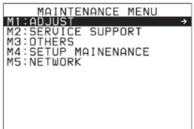
2 Turn the PUSH SET knob to select "M4 SETUP MAINTENANCE", then press the PUSH SET knob or the SELECT function button (F2).
The sub-items of M4: SETUP MAINTENANCE appears.
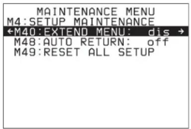
3 Turn the PUSH SET knob to select "M40 EXTENDED MENU", then press the PUSH SET knob or the SELECT function button (F2).
The setting screen for M40: EXTENDED MENU appears.
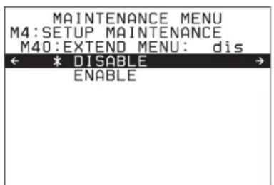
4 Turn the PUSH SET knob to select "ENABLE", and press the SAVE function button (F5).
The message “NOW SAVING...” appears on the video monitor screen, while the new settings are saved in memory. When the saving operation is completed, the video monitor screen returns to its normal indications.
When you next display the menu and change the item display, the extended menu will appear after the basic menu.
Maintenance Menu
Items in the maintenance menu
The following tables show the items in the maintenance menu.
- The values in the “Setting” column are the values that appear in settings screens. The values in brackets [ ] are the value shown in menu screens (when they differ from the values shown in settings screens).
- The underlined values are the factory defaults.
Refer to the Maintenance Manual for information about menu item M1: ADJUST and about M2: SERVICE SUPPORT settings not covered here.
M3: OTHERS: Other setting items
| Item Setting | |
| M30: SOFTWARE VERSION Display of the software version of this unit. |
| M31: SERIAL NUMBER Display of the serial number and Media Access Control (MAC) address of this unit. |
| M36: HOURS METER RESET Reset the display of resettable items of the operating hours meter. |
| H11: OPE HOURS | |
| M37: AUDIO CONFIG | M370: HEAD ROOM Select the audio reference level (headroom).-20dB, -18dB, -16dB, -12dB, EBULNoteEBUL can be selected only when the system frequency is 50i/25P. |
| M372: NON-AUDIO INPUT | Select whether to handle digital audio signals as non-audio signals during recording.audio: Handle as linear PCM audio signals.data: Handle as non-audio signals. |
| Sub-item |
| 1 tr1/tr2 |
| 2 tr3/tr4 |
| 3 tr5/tr6 |
| 4 tr7/tr8 |
| M373: IN LEVEL Set the upper limit for the signal level input to audio channels 1/3/5/7 or 2/4/6/8. |
| Sub-item | |
| 1 CH1/3/5/7 | NoteEBUL can be selected only when the system frequency is 50i/25P. |
| 2 CH2/4/6/8 |
| M377: OUT LEVEL Set the reference level for audio output signals.+4dB, 0dB, -3dB, -6dB, EBULNoteEBUL can be selected only when the system frequency is 50i/25P. |
| M38: F-KEY CONFIG | For details, refer to the Maintenance Manual. |
| M380: HOME2 Assign a function menu item to page HOME2 of the function menu as a user setting. |
| M381: PAGE6 ASSIGN Assign a setup menu item to page P6 of the function menu as a user setting. |
| M382: PAGE6 NAME Specify the name of a setup menu item assigned with M381: PAGE6 ASSIGN. |
M3: OTHERS: Other setting items
| Item | Setting |
| M39: OTHER CONFIG | M391: VITC REC Select wh | whether to record the VITC in the input HDSDI signals in the LTC user bits area.disable [dis]: Do not record.enable [ena]: Record.NotesRecording of VITC is enabled only when this is set to “enable,” and F1:TCG is set to “EXT” and F2:PRST/RGN is set to “TC” on the P4 TC page in the function menu.When set to “enable,” the value in the user bits area is output for VITC during playback. Note that the value of the user bits area is output for VITC even when playing back clips recorded without using this function.This setting has no affect during SD format recording/playback. |
| M395: FRMT MEDIA Spec | fy whether to disable the Format Media command of the Clip Menu.disable [dis]: Disable the Format Media command.enable [ena]: Enable the Format Media command. |
| M398: VDCP STATUS MODE | Set the operations to reflect in the VDCP status.VDCP [vdc]: Only operations via VDCP are reflected in the VDCP status.VDCP/FP/NetRMT [all]: Operations from VDCP, remote connection, and the front panel are reflected in the VDCP status. |
| M399: VERIFY USB | Specify whether to perform verification when copying data to the USB drive.off: Verification is not performed.on: Verification is performed. |
| M3B: VANC RX PARAMETER | M3B0: VANC RX PACKET | For setting HD-SDI VANC data input parametersNotesIn 59.94i, 50i, 29.97P or 25P mode, selecting the line also selects the corresponding line in the second field (for example, if line 9 is selected, line 572 is also selected for VANC packet reception).Menu item M3B0 enables recording of one VANC packet when the selected line contains any packets whose DID/SDID matches the value set with this menu item.Up to four packets are recorded per each line regardless of the DID and SDID for the VANC set with menu item M3B1 or M3B2.It is not possible to set the same line with menu items M3B0, M3B1, and M3B2. If the same line is specified, priority is given in the order of M3B0, M3B1, and M3B2 (for example, if the same line is specified with M3B0 and M3B1, the setting with M3B1 is ignored).When VANC data is output to HD-SDI playback signals, the number of the output VANC line is the same as that of the input VANC line.When a UMID or essence mark line is selected with M3B1 or M3B2, UMID or essence mark output takes priority. To disable UMID or essence mark output, set setup menu item 651 or 657 to “off”. |
| Sub-item |
| 1 LINE Selects the LINE for the VANC to be received.OFF, 9LINE to 20LINE (59.94i/50i/29.97P/25P/23.98P mode)OFF, 9LINE to 25LINE (59.94P/50P mode) |
| 2 DID Specification of the DID of the VANC to receive00h-FFh |
| 3 SD D Specification of the SDID of the VANC to receive00h-FFh |
| M3B1: LINE1 SEL Selects the LINE to be received for the HD-SDI VANC data.OFF, 9LINE to 20LINE (59.94i/50i/29.97P/25P/23.98P mode)OFF, 9LINE to 25LINE (59.94P/50P mode) |
| M3B2: LINE2 SEL Selects the LINE to be received for the HD-SDI VANC data.OFF, 9LINE to 20LINE (59.94i/50i/29.97P/25P/23.98P mode)OFF, 9LINE to 25LINE (59.94P/50P mode) |
| M3D: DATE/TIME PRESET | Specifies the year, month, day, time, and time zone. |
| M3E: USB MEMORY UTIL | For details, refer to the Maintenance Manual. |
| M3F: FACTORY SETUP | For details, refer to the Maintenance Manual. |
M4: SETUP MAINTENANCE: Items relating to the setup menu
| Item Setting | |
| M40: EXTENDED MENU Select whether to display the extended menu.DISABLE [dis]: Do not display.ENABLE [ena]: Display. |
| M48: AUTO RECALL Select whether to recall settings automatically from a menu bank when the system is powered on, and if so which menu bank to recall from.off: Do not recall settings from a menu bank.from BANK1 [Bank1]: Recall settings from menu bank 1.from BANK2 [Bank2]: Recall settings from menu bank 2.from BANK3 [Bank3]: Recall settings from menu bank 3. |
| M49: RESET ALL SETUP Reset all the menu settings to the factory settings.Push the SAVE function button (F5): Reset.Push the MENU button: Return to the next highest menu level without resetting.NotesThe password, area of use, and system frequency settings are also cleared. If you execute this item, reset the password, area of use, and system frequency (see page 24).Date and time settings are not cleared, but the time zone setting is cleared. After executing this item, reset the time zone (see page 24). |
M5: NETWORK: Items relating to network settings
| Item Setting | |
| M50: DHCP Set whether to assign an IP address automatically with the DHCP server.DIS: Do not assign automatically. DISABLE [dis]: ENABLE [ena]: Assign automatically. |
| M51: IP ADDRESS Set the IP address of this unit.192.168.001.010NotesIP address cannot be set when DHCP is set to “ENABLE”.To check the automatically acquired IP address of this unit, close the maintenance menu and then open it again. |
| M52: SUBNET MASK Set the subnet mask.255.255.255.000NotesSubnet mask cannot be set when DHCP is set to “ENABLE”.To check the automatically acquired subnet mask, close the maintenance menu and then open it again. |
| M53: DEFAULT GATEWAY Set the address of the default gateway.000.000.000.000NotesThe address of the default gateway cannot be set when DHCP is set to “ENABLE”.To check the automatically acquired address of the default gateway, close the maintenance menu and then open it again. |
| M54: LINK SPEED | Set the communications speed and protocol.AUTO [auto]: Sets automatically.1Gbps FullDuplex [1G F]: 1 Gbps, full duplex100Mbps FullDuplex [100 F]: 100 Mbps, full duplex100Mbps HalfDuplex [100 H]: 100 Mbps, half duplex10Mbps FullDuplex [10 F]: 10 Mbps, full duplex10Mbps HalfDuplex [10 H]: 10 Mbps, half duplex |
M5: NETWORK: Items relating to network settings
| Item Setting | |
| M56: JUMBO FRAMEa) | Set the size of jumbo frames.9014, 4088,OFF(1514)NoteThis value does not include the 4 bytes of the FCS (Frame Check Sequence). |
| M5B: SMB SUPPORT Set the version of | the SMB protocol to support.CIFS[cifs]:Supports CIFS/SMB 1.0.SMB3[smb3]:Supports up to SMB 3.1.1 used in Windows 10. |
| M5F: RESET NET CONFIG Reset network | k settings to the factory defaults.Push the SAVE function button (F5):Reset.Push the MENU button:Return to the next highest menu level without executing the reset.NoteExecuting RESET NET CONFIG clears the password setting, hence password setup will be required.After restarting, the PASSWORD SETUP screen appears. For details, see “Initial Setup” (page 24). |
a) A "jumbo" frame is a frame larger than the maximum 1514 bytes (not including FCS) of the standard Ethernet frame. Jumbo frames make it possible to deliver larger payloads per packet. Since fewer packets need to be routed, packet processing overhead is lower and network throughput is potentially improved. (Note that this item is enabled only when LINK SPEED is set to "1Gbps FullDuplex". For it to work, all other devices that handle packets on the network must also support jumbo frames.)
Maintenance menu operations
This section describes the indications in the maintenance menu and how to change the settings.
To display the maintenance menu
Holding down the PAGE/HOME button and the SHIFT button, press the MENU button.
The maintenance menu appears on the video monitor screen and the currently-set menu item is displayed in reverse video.
| On-screen indication Meaning |
| Right-pointing arrow (→) at the right of a menu item | Pressing the PUSH SET knob or the ➔ button switches to the next lower menu level or to a setting selection screen. |
| Left-pointing arrow (←) at the left of a menu item | Pressing the PUSH SET knob or the ← button switches to the previous (higher) menu level. |
| On-screen indication Meaning |
| Character string at the right of a menu item | Current setting of the menu itemWhen shown with a colon (:) : the current setting is the same as the factory default setting.When shown with a raised dot (.): the current setting is different from the factory default setting. |
| An * (asterisk) in a complete list of settings | Factory default setting |
Carry out the following operations to change the setting.
For information about how to change network settings see next section "To change network settings".
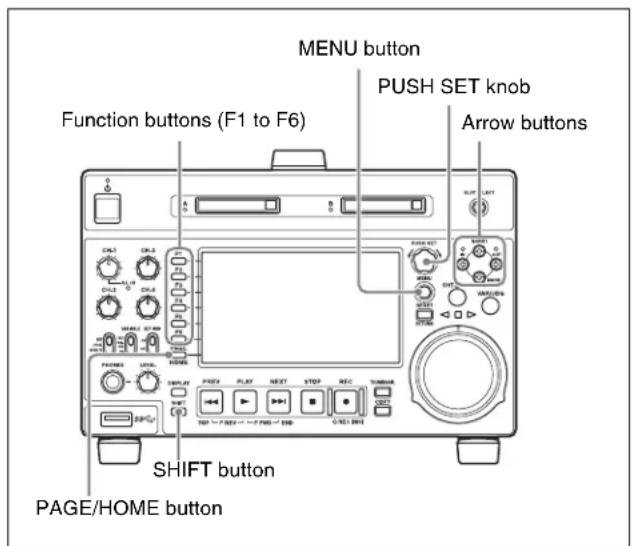
1 Use the PUSH SET knob or the and buttons to select the required item, then press the PUSH SET knob or the SELECT function button (F2).
The sub-items of the selected item appears.
2 Select a sub-item with the same operation as step 1, and use the PUSH SET knob or the ↑ and ↓ buttons to change the setting.
3 Press the PUSH SET knob or the SELECT function button (F2) to confirm the setting change.
4 Press the SAVE function button (F5).
The message “NOW SAVING...” appears on the video monitor screen, while the new settings are saved in memory. When the saving operation is completed, the video monitor screen returns to its normal indications.
To cancel changing a setting
Before pressing the SAVE function button (F5), press the MENU button.
The menu disappears from the video monitor screen, without saving the new setting.
To change network settings
To change network settings, carry out the procedure described in the previous section, “To display the maintenance menu”, to display the NETWORK menu item, then carry out the following operations.
For details of the settings, consult your network administrator.
When the IP address is assigned automatically
Note
Check that the network cable is connected to this unit before carrying out the operation.
1 Set maintenance menu item M5: NETWORK >M50: DHCP to "ENABLE".
2 In the NETWORK menu, press the SAVE function button (F5).
3 When the "NOW SAVING..." message vanishes, power the unit off and then on again with the on/ standby button.
To check the assigned IP address
Select maintenance menu item M5: NETWORK >M51: IP ADDRESS.
Note
If the IP address cannot be assigned, this is shown as "000.000.000.000". In this case, consult the network administrator.
To set the IP address
First set DHCP to “DISABLE” (see the previous section, “When the IP address is assigned automatically”).
1 Select maintenance menu item M5: NETWORK >M51: IP ADDRESS.
2 Press the PUSH SET knob.
The IP address appears, and the digit that can be changed flashes.
3 Set the IP address.
To select a different digit to be changed
Use the and buttons.
To change the value of a digit
Turn the PUSH SET knob.
Turning clockwise increases the value, and turning counterclockwise decreases the value.
The and buttons can also be used.
To return to the factory default setting
Press the RESET button.
4 When all digits are set, press the SAVE function button (F5).
This returns to the NETWORK menu.
5 Repeat steps 1 to 4 as required, to set the subnet mask and default gateway.
6 In the NETWORK menu, press the SAVE function button (F5).
7 When the message "NETWORK CONFIG WAS CHANGED. PLEASE REPOWER." appears, power the unit off and then on again with the on/standby button.
To set the communications speed and protocol
Set the communications speed and protocol (LINK SPEED) to match the network environment.
To set the communications speed and protocol, proceed as explained in the previous section “To display the maintenance menu” to display the NETWORK menu and then proceed as follows.
Contact your network administrator if you have any questions about the proper settings for these items.
1 Select maintenance menu item M5: NETWORK >M54: LINK SPEED.
2 Press the PUSH SET knob.
Combinations of the communications speed and protocol (1Gbps FullDuplex, 100Mbps FullDuplex, 100Mbps HalfDuplex, 10Mbps FullDuplex, 10Mbps HalfDuplex) appear, and the arrow flashes.
3 Press the PUSH SET knob or use the ↑ or ↓ button to select a combination of communications speed and protocol.
To return to the factory default setting Press the RESET button.
4 Press the SAVE function button (F5).
This returns to the NETWORK menu.
5 In the NETWORK menu, press the SAVE function button (F5).
6 When the message “NETWORK CONFIG WAS CHANGED. PLEASE REPOWER.” appears, power the unit off and then on again with the on/standby button.
Appendix
Important Notes on Operation
Use and storage
Do not subject the unit to severe shocks
The internal mechanism may be damaged or the body warped.
Do not cover the unit while operating
Doing so will cause temperatures to rise inside the unit, possibly resulting in failure.
After use
Turn off the on/standby button.
If you plan not to use the unit for a long time, turn off the POWER switch on the rear panel as well.
Shipping
- Remove the SxS memory card before transporting the unit.
- If sending the unit by truck, ship, air or other transportation service, pack it in the shipping carton of the unit.
Care of the unit
If the body of the unit is dirty, clean it with a soft, dry cloth. In extreme cases, use a cloth steeped in a little neutral detergent, then wipe dry. Do not use organic solvents such as alcohol or thinners, as these may cause discoloration or other damage to the finish of the unit.
In the event of operating problems
If you should experience problems with the unit, contact your Sony representative.
Use and storage locations
Store in a level, ventilated place. Avoid using or storing the unit in the following places.
- In excessive heat or cold (operating temperature range: 5^ to 40^ ( 41^ to 104^ ))
Remember that in summer or in warm climates the temperature inside a car with the windows closed can easily exceed 50^ C ( 122^ F).
• In damp or dusty locations
- Locations where the unit may be exposed to rain
- Locations subject to violent vibration
• Near strong magnetic fields
- Close to radio or TV transmitters producing strong electromagnetic fields.
- In direct sunlight or close to heaters for extended periods
To prevent electromagnetic interference from portable communications devices
The use of portable telephones and other communications devices near this unit can result in malfunctions and interference with audio and video signals.
It is recommended that the portable communications devices near this unit be powered off.
About the LCD panel
The LCD panel fitted to this unit is manufactured with high precision technology, giving a functioning pixel ratio of at least 99.99%. Thus a very small proportion of pixels maybe “stuck”, either always off (black), always on (red, green, or blue), or flashing. In addition, over a long period of use, because of the physical characteristics of the liquid crystal display, such “stuck” pixels may appear spontaneously. These problems are not a malfunction. Note that any such problems have no effect on recorded data.
Network
SONY WILL NOT BE LIABLE FOR DAMAGES OF ANY KIND RESULTING FROM A FAILURE TO IMPLEMENT PROPER SECURITY MEASURES ON TRANSMISSION DEVICES, UNAVOIDABLE DATA LEAKS RESULTING FROM TRANSMISSION SPECIFICATIONS, OR SECURITY PROBLEMS OF ANY KIND.
Depending on the operating environment, unauthorized third parties on the network may be able to access the unit. When connecting the unit to the network, be sure to confirm that the network is protected securely.
Periodic Maintenance
Operating hours meter
The operating hours meter can provide two items of information about the operational history of the unit. The information can be displayed by text superimposition, on the monitor connected to the unit. Use the information as a guide in scheduling periodic maintenance.
For periodic maintenance, consult a Sony service representative.
Display modes of the operating hours meter
Displays the total number of hours the unit has been powered on in units of 1 hour.
H11: OPERATION HOURS mode (resettable)
Same as H01 except that the count is resettable.
This can be used as a guide in determining when to replace parts.
To display the operating hours meter
Press the MENU button to display the setup menu, then turn the PUSH SET knob to display the required item on the monitor connected to the unit.
To exit from the operating hours meter
Press the RETURN function button (F1) to return to the setup menu.
Press the EXIT function button (F6) to return to the screen that was displayed before you entered the setup menu.
Troubleshooting
Alarms
An alarm (warning message) appears in the status display area when an operation is attempted which is inappropriate for the settings on this unit or the state of a media. Both the alarm message and the action to take to resolve the problem appear on the video monitor screen.
Note
If “display off: DISPLAY KEY” appears below the alarm display, you can press the DISPLAY button to dismiss the alarm display.
High TEMP!
Example alarm in status display area
ALARM
HIGH TEMPERATURE.
Example alarm in video monitor screen
When an alarm is displayed, remove the alarm cause by following the action to take. If the alarm display does not disappear, contact your Sony representative.
When the unit is powered on
| Alarm message in status display area | Alarm message in video monitor screen | Description/action |
| ILL. SETUP! INVALID SETTINGS SELECTED INSETUP MENU.SET ITEMS IN THE SETUP MENU TOTHE APPROPRIATE VALUES.CONTACT SERVICE IF THIS ALARMAPPEARS AGAIN AFTER ABOVEPROCEDURE. | Reset the settings in the setup menu (see page 76).If the same message appears after you reset thesettings, contact your Sony representative. |
| Exchg batt! BATTERY NEEDS REPLACING.PLEASE CONTACT SERVICE. | The battery of the internal clock is exhausted.Contact your Sony service or sales representative. |
| Run Software UpdateProgram. | RUN SOFTWARE UPDATE PROGRAM. The software update is not properly performed.Update the software version again. If the samemessage appears after you update the softwareversion, contact your Sony representative. |
When a memory card is inserted
| Alarm message in status display area | Alarm message in video monitor screen | Description/action |
| Unknown Media(A/B) UNKNOWN MEDIA(A/B).PLEASE CHANGE. | The inserted memory card exceeds the capacity supported by the unit, the memory card has been partitioned, or the memory card contains more clips than the maximum that can be handled by this unit. Insert a memory card that has not been partitioned, or one that contains fewer than the maximum number of clips. |
| Memory (A/B) needsRestoring. | MEDIA ERROR.MEDIA(A/B) NEEDS TO BE RESTORED. | A memory card must be restored because an error has occurred in the card.Restore the card or format it. |
| Memory(A/B) Error! MEDIA | (A/B) CANNOT BE RESTORED.PLEASE RESTORE IT USING THE RECORDED EQUIPMENT. | An abnormality has occurred on the memory card, and data restoration is needed. Perform data restoration on the device that was used to record to the memory card in question. |
| Unknown FS!(A/B) CANNOT | USE MEDIA(A/B). UNSUPPORTED FILE SYSTEM. | The inserted memory card is formatted with an unsupported file system, or it is not formatted. Format the memory card, or exchange the memory card for one that is formatted with a file system supported by this unit. |
| R/W Limit(A/B) MEDIA REACHED REWRITE LIMIT.CHANGE MEDIA(A/B). | The memory card has reached its lifetime rewriting limit.Copy clips on the memory card to other media as required, and then exchange the memory card.NoteIf you continue to use the memory card, normal recording and playback may not be possible. |
| Over DUR!(A/B) EXCESSIVE DURATION IS IN MEDIA(A/B). | A clip with a duration that exceeds 24 hours is recorded on a memory card.This memory card cannot be used. |
| Under Repair of Media (A/B) | MEDIA (A/B) IS BEING REPAIRED. Automatic repair for the management area of the memory card is in progress.Wait until the automatic repair is complete. |
| Repair Failed (A/B) REPAIR | FAILED. The memory card is damaged, and recording and playback are not possible.Replace the memory card. |
When a folder in the external storage is being mounted
| Alarm message in status display area | Alarm message in video monitor screen | Description/action |
| USB DRV Error! USB DRIVE | CANNOT BE RESTORED.PLEASE RESTORE IT USING THE RECORDED EQUIPMENT. | The operation target folder in the external storage needs data restoration. Perform data restoration on the device that was used to record to the external storage in question. |
| USB DRV needs Restoring. | MEDIA ERROR.USB DRIVE NEEDS TO BE RESTORED. | An abnormality has occurred with the operation target folder on the external storage or the folder was edited by another device, and data restoration is needed. Perform data restoration on the external storage in question or format it. |
| Over DUR!(USB DRV) EXC | ESSIVE DURATION IS IN USB DRIVE. | The total length of the clips stored in the operation target folder in the external storage exceeds 24 hours. This operation target folder cannot be used. |
| Remove Memory-B and Select Memory Slot-B. | – To mount external storage, first remove the SxS memory card from card slot B and then select slot B. |
| USB Drive not mounted due to limit of files or unsupported sector size. | – The number of files exceeds 20,000 or external storage with an unsupported sector size is connected. Replace with other external storage. |
During front panel operations
| Alarm message in status display area | Description/action |
| KEY INHI.! This appears when the KEY INHI switch is “ON”. Set the KEY INHI switch to “OFF”. |
| Not Open Clip! This appears when a clip operation is attempted with no clip selected. Select a clip in the clip list screen and try the operation again. |
| Clip Top! During playback, this appears if you execute a reverse search when the unit is stopped at the first frame of a clip. To move to another clip, press the PREV, NEXT, SHIFT + PREV, or SHIFT + NEXT button, or perform a thumbnail search. |
| Clip End! During playback, this appears if you execute a forward search when the unit is stopped at the last frame of a clip. To move to another clip, press the PREV, NEXT, SHIFT + PREV, or SHIFT + NEXT button, or perform a thumbnail search. |
| EDL Top! During EDL playback, this appears if you press the PREV button at the first frame of the first sub clip of an EDL. |
| EDL End! During EDL playback, this appears if you press the NEXT button at the last frame of the last sub clip of an EDL. |
| MAX # Clips No more clips can be recorded because the maximum number of recorded clips has been reached. Delete unneeded clips. |
| Media Full! Recording or copying is not possible because the media is full. Delete unneeded clips. |
| TC EXT! This appears when TCG on page P4 TC of the function menu is set to “EXT”, and you try to preset timecode or user bits by setting PRST/RGN to “PRESET”. Set TCG to “INT” (see page 39). |
| REGEN mode! This appears when PRST/RGN on page P4 TC of the function menu is set to “TC” or “VITC”, and you try to preset timecode or user bits. Set PRST/RGN to “PRESET” (see page 39). |
| REC mode! Stop recording and try again. |
| STOP ONCE! This appears when an attempt is made to change media during recording or playback. Stop the recording or playback and try the operation again. |
| Exit THUMBNAIL mode! This appears when an attempt is made to change media while the clip list screen is displayed. Switch to the basic operation screen or the video monitor screen and try the operation again. |
| REMOTE! | Press the REMOTE button, turning it off, to put this unit into local control mode. |
| No Media! | Try again after loading an SxS memory card. |
| Media Top! An attempt has been made to execute a reverse search when the unit is stopped at the first frame of the first clip during playback of a memory card. |
| Media End! | An attempt has been made to execute a forward search when the unit is stopped at the last frame of the last clip during playback of a memory card. |
| REC INHI! | Set the write protect switch on the memory card so as to enable recording (see page 41). |
| No EM Space | This appears when any essence mark was not recorded because there is no space before and after the desired position. Delete unneeded shot marks 0 to 9 in the chapter thumbnail screen. |
| EM Full! | This appears when no more essence marks can be recorded. Delete unneeded shot marks 0 to 9 in the chapter thumbnail screen. |
| Illegal Operation! | This appears when an attempt is made to carry out an invalid operation. |
| Media is not Ready. | The media is in the course of being mounted or has not been loaded. |
During recording operations
| Alarm message in status display area | Alarm message in video monitor screen | Description/action |
| REC INHI! THE MEDIA WRITE PROTECT TAB IS SET TO SAVE. | Set the write protect switch on the memory card so as to enable recording (see page 41). |
| ILL. REC! ENCODING DOES NOT SYNCHRONIZE WITH REF VIDEO. | Check the signals being input to this unit. |
| MEM. Full! MEMORY FULL !! Recording on a media is not possible because a buffer overflow has occurred in the recording buffer memory. |
| REC ERR! RECORDING ERROR DETECTED. An unrecoverable error occurred when recording. A part of the recorded clip will be missing. |
| REC STOP WITHIN 2MIN RECORDING IS TERMINATED WITHIN 2 MINUTES AUTOMATICALLY.BECAUSE THE CLIP IS REACHED TO MAXIMUM DURATION. | The length of the clip has reached the maximum limit during recording. Recording will stop within the next two minutes. |
| The total recording time has reached the maximum limit during recording. Recording will stop within the next two minutes. |
| The Upper limits of Files Reached. | – The limit for the number of files that can be recordedhas been reached.Delete unnecessary files, or use a different folder on the USB drive. |
| Cannot Switch Slots – No recordable media is inserted. | Insert a recordable media. |
| Media Needs to be formatted for Relay Recording. | MEDIA NEEDS TO BE FORMATTED FOR RELAY RECORDING. | The media for relay recording has a different file system.Format the media with the same file system or exchange with media with the same file system. |
| Will Switch Slots Soon – Displayed two minutes before switching memory cards |
| Switching Slot | – Displayed while switching memory card slots. |
| Switched Slot | – Displayed after switching memory card slots. |
During playback operations
| Alarm message in status display area | Alarm message in video monitor screen | Description/action |
| ILL. PLAY! | ILLEGAL PLAYBACK. | Normal playback is not possible. |
| MEM. Empty! | MEMORY EMPTY !! | Playback is not possible because a buffer underflow has occurred in the playback buffer memory. |
| Media Data Error! | MEDIA DATA ERROR DETECTED. | A media error has been detected.Replace the media. |
| This Clip cannot be Played back. | - This clip cannot be played back because its format is not supported by this unit.No clips in the USER folder can be played back. |
| No MEDIA! | - First insert a memory card or mount the external storage USB drive (see page 43), and then proceed to the operation. |
| MEMORY Busy! | - Playback is not possible because the memory card is being used. |
| Operation is not Supported for EDL. | - An EDL cannot be played back. | Select a clip. |
| MEMORY Busy! NETWORK | - The memory card cannot be played as it is currently being used on the network. |
During operations in the clip list screen/thumbnail search/EDL editing/copy
| Alarm message in clip list screen | Description/action |
| Clip is Locked. The clip is locked. | This appears when an attempt is made to delete a clip, or set or clear a clip flag when the clip is locked. |
| Copy Running! A copy operation is being performed, so another copy operation is not allowed. |
| Operation Failed! The target operation failed because of generation of an internal error. |
| Not Supported Format. The format is not supported by this unit, so copy operation is impossible.Copy Aborted. |
| Copy Aborted. The copy operation was aborted. |
| Some Clip(s) are Locked. Some of the selected clips are locked (protected). |
| Clip Error. The clip is substandard, so the copy operation failed. |
| Set Appropriate IN/OUT Points. | The settings of IN and OUT points for partial copy operation are not proper.Check the IN and OUT point settings. |
| No Clip! The clip selected for expansion or chapter display has been deleted. Alternatively, the memory card has been ejected. |
| Cannot Expand Clip any Further. | The selected clip cannot be divided any further to display the expand thumbnails.This alarm appears when the expand thumbnails of a clip divided into the maximum number of blocks are displayed or when the EXPAND function button has been pressed with the expand thumbnail screen displayed in which the duration of each block is one frame. |
| Delete is Prohibited.This Clip is in Use. | The target clip is being used, so it cannot be deleted. |
| Delete is Prohibited.Referring EDL is in Use. | The EDL which refers to the target clip is being used, so the clip cannot be deleted. |
| Delete is Prohibited. Deletioon of the target clip has failed. |
| Lock/Unlock is Prohibited.This Clip is in Use. | The target clip is being used, so it cannot be locked/unlocked. |
| Lock/Unlock is Prohibited. Lock/unlock of the target clip has failed. |
| Set Clip Flag was not Performed. | Set Clip Flag function has failed. |
| One Clip is being Recorded.Use Single Selection. | One of the selected clips was being recorded.To copy a clip which is being recorded, make a single selection of the clip. |
| Operation is not Supported for EDL. | You cannot select EDL to delete an essence mark or set a shot mark. |
| Adding EM was not Performed. | Essence mark setting has failed. |
| Over DUR! A clip with a duration that exceeds six hours cannot be copied. |
| Cannot Display Chapter of this Clip. | The selected clip has failed in chapter thumbnail display.Stop recording of a clip if any in progress. |
| Chapter was Changed.Display Again. | The chapter setting information has been updated.Try again the chapter thumbnail display. |
| Chapter does not Exist. | Chapter thumbnail screen cannot be displayed because no chapters are set on the clip. |
| Cannot Expand this Clip. | The clip cannot be expanded because it is being recorded. |
| Unable to Parse the EDL. | The EDL cannot be copied due to existence of an inhibiting condition such that there is no sub clip. |
| Out of Remain Space! | The remaining capacity of the copy destination media is not sufficient. |
Alarms relating to audio and video signals
| Alarm message in status display area | Alarm message in video monitor screen | Description/action |
| No INPUT! INPUT VIDEO | IS NOT DETECTED.CHECK THE VIDEO INPUT MODE AND SUPPLY A VIDEO SIGNAL TO VIDEO INPUT. | Check the setting of V INPUT on page P1 INPUT of the function menu (see page 38).Input an HDSDI signal. |
| EMPHASIS! INPUT AUDIO | EMPHASIS IS NOT SUPPORTED.CHECK THE EMPHASIS OF THE AUDIO INPUT SIGNAL. | Check the emphasis of the audio input signal. |
| REF Not Exist – Input a reference signal. | |
| REF NON-STD A NON-STANDARD REF SIGNAL ISBEING USED FOR REF VIDEO.USE A STANDARD SIGNAL. | Input a standard reference signal. |
| Input Sig! VIDEO INPUT SIGNAL DOES NOTMATCH SYSTEM SETUP. | This appears when the signal that does not correspond to the system frequency or the number of lines set in this unit is being input, or when HD-SDI is selected as a video input signal while setting the SD signal recording.Input a signal that matches the system frequency, or change this unit's system frequency setting (see page 33). |
Alarms relating to sensors and drivers
| Alarm message in status display area | Alarm message in video monitor screen | Description/action |
| MEM-138 Warning IT IS NE | ESSESARY TO REPLACE MEM-138.PLEASE CONTACT SERVICE. | Contact your Sony representative.NoteThe unit will not stop operating, but if you continue to use it in this state, it may get broken sooner or later, resulting in a total loss of the information. |
| FAN(1/2/3) Error | FAN1(1/2/3) ERROR. | Contact your Sony representative.NoteThe unit will not stop operating, but if you continue to use it in this state, temperatures inside the unit will rise, possibly resulting in failure or fire. |
| FAN1 Warning | FAN1 WARNING. |
| High TEMP! | HIGH TEMPERATURE. |
Other alarms
| Alarm message in status display area | Alarm message in video monitor screen | Description/action |
| Turn off/on POWER!! | SYSTEM CONFIGURATION WAS CHANGED. PLEASE TURN OFF/ON POWER. | The system frequency was changed. Power off this unit and then power it on again. |
| Turn off/on POWER!! | MENU CONFIG WAS CHANGED. PLEASE TURN OFF/ON POWER. | Menu settings were changed. To put the change of menu settings into effect, power this unit off and then power it on again. |
| Access Err!(A/B) | ACCESS ERROR. PLEASE EJECT MEDIA(A/B). | The memory card could not be accessed. Reinsert the memory card or replace it with another memory card. |
| Completed only XML file | - Only the metadata file was updated, without updating the metadata in the MXF file. |
| Format Media is Prohibited. Confirm Mainte Menu : M395. | - An attempt was made to execute Format Media while use of the Format Media command is prohibited by maintenance menu item M395. Check maintenance menu item M395. |
| SxS-1/XQD are Not Guaranteed Media | – This message is displayed if the unit is started withXAVC selected as the recording format or if XAVC is selected in setup menu item 031 RECORDING FORMAT.When the recording format is XAVC, use SxS PRO+, SxS PRO X, or SxS PRO media. |
Error messages
Error codes appear in the status display area when an error (usually a hardware problem) occurs. In addition, both error messages and error codes appear on the video monitor screen.
When an error message appears, follow the instructions in the error message to resolve the problem.
Note
If “display off: DISPLAY KEY” appears below the error display, you can press the DISPLAY button to dismiss the error display. In this case, the error is displayed only in the status display area, on the video monitor screen, and on a PC monitor connected to the unit.

Example error code in status display area
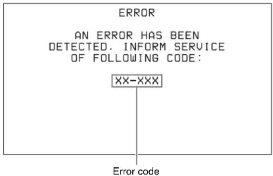
Example error message in video monitor
Specifications
General
External dimensions (w/h/d, excluding projections)
$$
2 1 0 \times 1 3 2 \times 4 1 8 \mathrm{mm}
$$
$$
(8 ^ {3} / _ {8} \times 5 ^ {1} / _ {4} \times 1 6 ^ {1} / _ {2} \text { inches })
$$
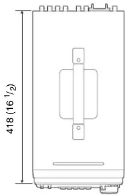
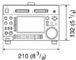
in mm (inches)
Mass 5.0 kg (11 lb 0.37 oz)
Power requirements
$$
1 0 0 \mathrm{V} \text { to } 2 4 0 \mathrm{V} \mathrm{AC}, 5 0 / 6 0 \mathrm{Hz}
$$
$$
1 2 \mathrm{VDC}
$$
Power consumption
$$
\mathrm{AC~operation:} 8 0 \mathrm{W}
$$
$$
D C \text { operation: } 5. 7 A
$$
Inrush current
(1) Maximum possible inrush current at initial switch-on (Voltage changes caused by manual switching): 58 A peak, 8 A r.m.s. (240 V AC)
(2) Inrush current after a mains interruption of five seconds (Voltage changes caused at zero-crossing): 15 A peak, 4 A r.m.s. (240 V AC)
Operating temperature
$$
5 ^ {\circ} \mathrm{C} \text { to } 4 0 ^ {\circ} \mathrm{C} (4 1 ^ {\circ} \mathrm{F} \text { to } 1 0 4 ^ {\circ} \mathrm{F})
$$
Storage temperature
$$
- 2 0 ^ {\circ} \mathrm{C} \text {to} + 6 0 ^ {\circ} \mathrm{C} (- 4 ^ {\circ} \mathrm{F} \text {to} + 1 4 0 ^ {\circ} \mathrm{F})
$$
Operating humidity
$$
20\% \text{ to } 90\% \text{ (relative humidity)}
$$
Storage humidity
$$
5 \% \text { to } 80 \% (\text { relative humidity })
$$
System
XAVC Intra
Video MPEG-4 AVC/H.264,
$$
\text { Intra max. } 1 1 2 \mathrm{Mbps}
$$
Audio 24 bit, 48 kHz, 8 ch
XAVC Long
Video MPEG-4 AVC/H.264,
$$
\text { Long max. } 5 0 / 3 5 / 2 5 \text { Mbps }
$$
Audio 24 bit, 48 kHz, 8 ch
MPEG HD422
Video MPEG HD422: 50 Mbps
Proxy video MPEG-4
Audio 24 bit, 48 kHz, 8 ch
Proxy audio A-law 8 bit, 8 kHz, 8 ch
MPEG HD
Video MPEG HD: HQ35/SP25/LP18 Mbps
1)
Proxy video MPEG-4
Audio 16 bit, 48 kHz, 4/2 ch
Proxy audio A-law 8 bit, 8 kHz, 4 ch
MPEG IMX 2)
Video MPEG IMX: 50/40/30 Mbps
Proxy video MPEG-4
Audio 24/16 bit, 48 kHz, 4/8 ch
Proxy audio A-law 8 bit, 8 kHz, 4/8 ch
DVCAM
Video DVCAM: 25 Mbps
Proxy video MPEG-4
Audio 16 bit, 48 kHz, 4 ch
Proxy audio A-law 8 bit, 8 kHz, 4 ch
1) MPEG HD 25 and 18 Mbps can be used for playback only.
2) MPEG IMX can be used for playback only.
Recording/playback times
| File system/file format | Recording mode | Recording time (minutes) |
| 32 GB | 64 GB | 128 GB | 256 GB |
| UDF/MXF | HD422 mode (50 Mbps CBR) | Approx. 60 | Approx. 120 | Approx. 240 | Approx. 480 |
| HQ mode (35 Mbps VBR) | Approx. 90 | Approx. 180 | Approx. 360 | Approx. 720 |
| IMX50 mode^1) (50 Mbps Intra) | Approx. 60 | Approx. 120 | Approx. 240 | Approx. 480 |
| DVCAM (25 Mbps) | Approx. 110 | Approx. 220 | Approx. 440 | Approx. 880 |
| FAT/MP4^1) | HQ mode (35 Mbps VBR) | Approx. 100 | Approx. 200 | Approx. 400 | Approx. 800 |
| SP mode (25 Mbps CBR) | Approx. 140 | Approx. 280 | Approx. 560 | Approx. 1120 |
| FAT/AVI^1) | DVCAM (25 Mbps) | Approx. 130 | Approx. 260 | Approx. 520 | Approx. 1040 |
| exFAT/MXF | XAVC Intra (100 Mbps CBG) | Approx. 30 | Approx. 60 | Approx. 120 | Approx. 240 |
| XAVC Long (50 Mbps VBR) | Approx. 60 | Approx. 120 | Approx. 240 | Approx. 480 |
| XAVC Long (35 Mbps VBR) | Approx. 85 | Approx. 170 | Approx. 340 | Approx. 680 |
| XAVC Long (25 Mbps VBR) | Approx. 110 | Approx. 220 | Approx. 440 | Approx. 880 |
1) Playback only
Note
The recording and playback times listed above are approximate. Maximum recording times may vary depending on recording conditions.
Search speed
Jog mode -1 to +1 times normal speed (during remote control: -2 to +2 times normal speed)
Variable mode -2 to +2 times normal speed
Shuttle mode -20 to +20 times normal speed (during remote control: -50 to +50 times normal speed)
F. FWD mode +35 times normal speed (during remote control: +50 times normal speed)
F. REV mode -35 times normal speed (during remote control: -50 times normal speed)
Sampling frequency
Y: 74.25 MHz, R-Y/B-Y: 37.125 MHz
Quantization MPEG HD422/MPEG HD/DVCAM: 8 bits/sample
XAVC: 10 bits/sample
Compression HD422 MPEG-2 422P@HL
HD: MPEG-2 MP@HL/H-14
XAVC: MPEG-4 AVC/H.264 Intra
Composite output
Frequency response
0.5 to 5.75 MHz +0.5/-2.0 dB
S/N (Y) 53 dB or more
Y/C delay ±20 ns or less
K-factor (K2T) 1.0% or less
Processor adjustment range
Video level - to +3 dB
Chroma level - to +3 dB
Set up/black level
±30 IRE/±210 mV
Chroma phase ±30°
System phase SYNC: ±15 μs
SC: 0 to +400 ns
Sampling frequency
48 kHz
Quantization 24 bits
Headroom -20/-18/-16/-12/-9 (EBU level)
(selectable)
Frequency response
20 Hz to 20 kHz +0.5/-1.0 dB (0 dB at 1 kHz)
Dynamic range 90 dB or more
Distortion 0.05% or less (at 1 kHz)
SD/HDSDI INPUT
BNC type, complying with SMPTE ST 259 (SD)/SMPTE ST 292-1 (HD)
REF.VIDEO INPUT
BNC type (2) (loop-through), HD Tri-level sync (0.6 Vp-p, 75 Ω, sync positive/negative), SD black burst, or SD composite sync (0.286 Vp-p (NTSC), 0.3 Vp-p (PAL), 75 Ω, sync negative)
ANALOG AUDIO INPUT 1, 2
XLR 3-pin, female (2), +4 dBu, high impedance, balanced
TIME CODE IN
BNC type, SMPTE timecode, 0.5 to 18 Vp-p, 3.3 kΩ, unbalanced
Output connectors
Digital video outputs
HDSDI OUTPUT 1, 2 (SUPER)
BNC type (2), complying with SMPTE ST 292-1
SDSDI OUTPUT 1, 2 (SUPER)
BNC type (2), complying with SMPTE ST 259
HDMI OUT Type A 19-pin
Video: 1080i, 720P, 480i, 480P, 576i, 576P
Audio: Linear PCM, 48kHz/16-bit, 2 channels
Analog video outputs
COMPOSITE OUTPUT 1, 2 (SUPER)
BNC type (2), 1.0 Vp-p, 75 Ω, sync negative, complying with SMPTE ST 170
Analog audio outputs
ANALOG AUDIO OUTPUT 1,2
XLR 3-pin, male (2), +4 dBu, 600 Ω load, low impedance, balanced
AUDIO MONITOR
XLR 3-pin, male (2), +4 dBu, 600 Ω load, low impedance, balanced
PHONES
Stereo phone jack, - to -13 dBu, 8 , unbalanced
Timecode output
TIME CODE OUT
BNC type, SMPTE timecode, 1.0 Vp-p, 75 Ω, unbalanced
Remote control connectors
REMOTE (9P) D-sub 9-pin, female, complying with RS-422A
REMOTE 4-pin, female
DC 12 V, 7.5 W
(Network) RJ-45 type
1000BASE-T: complying with IEEE802.3ab
100BASE-TX: complying with IEEE802.3u
10BASE-T: complying with IEEE802.3
USB connectors
USB3.0 (front)
Super Speed USB (USB 3.0) Type-A
MAINTENANCE (rear)
High Speed USB (USB 2.0) Type-A (2)
Accessories supplied
Operation guide (1)
CD-ROM manual (1)
Accessories not supplied
AC power cord
- For the customers in the U.S.A and Canada
Part number 1-551-812-31 (125 V, 10 A, about 2.4 m)
- For the customers in the United Kingdom
Part number 1-833-259-12 (250 V, 10 A, about 2.0 m)
- For the customers in European countries other than the United Kingdom
Part number 1-551-631-16 (250 V, 10 A, about 2.0 m)
RCC-5G 9-pin Remote Control Cable
RM-280 Remote Edit Controller
BP-GL95B Battery Pack
BKP-L551 Battery Adaptor
SxS memory cards
SxS PRO+ series
SxS PRO series
SxS PRO X series
SxS-1 series
XQD memory card series
XQD memory cards
QD-H16 (16 GB), QD-H32 (32 GB),
QD-S32 (32 GB), QD-S64 (64 GB),
QD-G32A (32 GB), QD-G64A
(64 GB), QD-G128A (128 GB),
QD-M32A (32 GB), QD-M64A
(64 GB), QD-M128A (128 GB)
QDA-EX1 XQD Express Card Adapter
MEAD-MS01 Media Adapter (for “Memory Stick PRO-HG Duo” HXA series)
MEAD-SD01 SD Card Adapter (for SDHC card)
MEAD-SD02 SD Card Adapter (for SDHC/SDXC card)
Note
This unit does not support memory cards exceeding 256 GB, excluding SDXC cards.
Design and specifications are subject to change without notice.
Notes
- Always make a test recording, and verify that it was recorded successfully. SONY WILL NOT BE LIABLE FOR DAMAGES OF ANY KIND INCLUDING, BUT NOT LIMITED TO, COMPENSATION OR REIMBURSEMENT ON ACCOUNT OF FAILURE OF THIS UNIT OR ITS RECORDING MEDIA, EXTERNAL STORAGE SYSTEMS OR ANY OTHER MEDIA OR STORAGE SYSTEMS TO RECORD CONTENT OF ANY TYPE.
• Always verify that the unit is operating properly before use. SONY WILL NOT BE LIABLE FOR DAMAGES OF ANY KIND INCLUDING, BUT NOT LIMITED TO, COMPENSATION OR REIMBURSEMENT ON ACCOUNT OF THE LOSS OF PRESENT OR PROSPECTIVE PROFITS DUE TO FAILURE OF THIS UNIT, EITHER DURING THE WARRANTY PERIOD OR AFTER EXPIRATION OF THE WARRANTY, OR FOR ANY OTHER REASON WHATSOEVER.
Using UMID Data
Metadata is additional information recorded on SxS memory cards along with audio-visual data. It is used to bring greater efficiency to the flow of operations from material acquisition through editing, and to make it easier to find and reuse material.
As one of application of metadata, the UMID has been internationally standardized.
What is a UMID?
A UMID (Unique Material Identifier) is a unique identifier for audio-visual material defined by the SMPTE ST 330:2004 standard.
A UMID may be either as a 32-byte Basic UMID or an Extended UMID, which includes an additional 32 bytes of Source Pack to make a total 64 bytes.
For details, refer to SMPTE ST 330.
Extended UMID (64 bytes)
| Basic UMID (32 bytes) Source Pack (32 bytes) |
| Universal label L | | Instance No. | Material Number | Time/Date | Spatial Coordinates | Country | Org User |
| 12 bytes | 1 | 3 bytes | 16 bytes | 8 bytes 12 | bytes | 4 bytes | 4 bytes 4 | bytes |
A globally unique ID is automatically recorded for every clip.
The Extended UMID is metadata that provides additional information such as location, time/date, company ID and so on.
The UMID is applied as follows.

Original material: 00 00 00
Copied material: generation number (1 byte)
+ random number (2 bytes)

Distinguish between the original material and copied material

Material source ID/detecting material

Metadata pack that identifies the source of material unit by defining the when, where and who of the material unit with which it is associated.
Using the Extended UMID
You have to enter a country code, organization code and user code. Set the country code referring to the table in ISO 3166, and set the organization code and user code according to the guidelines of your organization.
For details, see “Setting UMID ownership information” (page 115).
Functions of UMID data
UMID data enables the following:
- Addition of a globally unique ID to every clip of audiovisual material. The unique ID is used to detect the material source and to link it with the original source material.
- Distinguishing between original material and copied material. 00 is added to the Instance Number for original material.
- Recording with UTC time. UTC (coordinated universal time) is used when recording the UMID. Use of a universal time system enables uniform management of source material recorded all over the world.
- Calculation of date differences. Source material is recorded using modified Julian dates (MJD), which enables easy calculation of date differences between different source material items.
Proceed as follows.
1 Set setup menu item 029 STORED OWNERSHIP to "on" (see page 79).
See page 80 for more information about setup menu operations.
The STORED OWNERSHIP (UMID ownership information setting) screen appears.
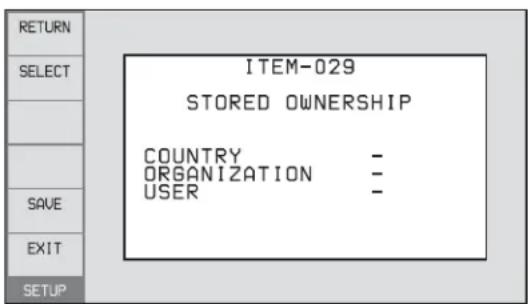
COUNTRY: Sets the country code.
ORGANIZATION: Sets the organization code.
USER: Sets the user code
See the next item “About the UMID ownership information” for more information about these codes.
2 Use the PUSH SET knob to select the item to set and the character input location, then press the knob.
3 Use the PUSH SET knob, - or + function button (F3 or F4) to select characters to input at the selected location.
To delete all input data
Press the RESET/RETURN button.
4 Press SAVE function button (F5).
The message “NOW SAVING...” appears, and the ownership information is saved.
COUNTRY (country code)
Set the country code by entering an abbreviated alphanumeric string (4-byte alphanumeric string) according to the values defined in ISO 3166-1.
There are about 240 country codes.
Find your own country code on the following web page.
Refer to ISO 3166-1:
http://www.iso.org/iso/country-codes/iso_3166_code_lists.htm
When the country code is less than 4 bytes, the active part of the code occupies the first part of the 4 bytes and the remainder must be filled with the space character (20h).
Example: Japan
For Japan, the country code is JP, which is 2 bytes, or JPN, which is 3 bytes.
Thus, enter the following:
JP_ _
or
JPN _
where
ORGANIZATION (organization code)
Enter a 4-byte alphanumeric string for the organization code.
Notes
- There are no problems in recording or playing back audio-video signals, even if the ORGANIZATION is not set.
- Organization codes must be acquired by applying to the SMPTE registration office. When no organization code has been acquired, it is forbidden to enter an arbitrary string. As a rule, the code “00” must be entered.
Freelance operators who do not belong to an origination should enter “\~”.
USER (user code)
Enter a 4-byte alphanumeric string to identify the user. The user code is registered with each organization locally. It is usually not centrally registered.
When the user code is less than 4 bytes, enter the user code at the beginning of the 4 bytes and fill the remainder of the string with the space character (20h).
This user code is determined by the organization. The methods used depend on the organization.
Note
User code cannot be entered when no organization code has been entered.
Ancillary Data
This unit can play and record ancillary data multiplexed into HDSDI signals. It can also input and output ancillary data in MXF files when transferring files via FTP/CIFS connections. Transferable auxiliary data includes text data (captions and metadata) and control signals.
Ancillary data in HDSDI/SDSDI signals
This unit can record and play back closed captions conforming to the EIA-708-B ^1) standard and EIA-608-B ^1) standard, and text data conforming to the ARIB TR B-23 ^2) standard which comprise the VANC (Vertical ancillary data) packets.
1) EIA: Electronic Industries Alliance
2) ARTB: Association of Radio Industries and Businesses
To record ancillary data
In maintenance menu, set the lines where ancillary data is inserted, the DID (Data Identifier word), and the SDID (Secondary Data Identifier word).
For details, refer to maintenance menu item M3B (page 96).
To record and playback EIA-708-B standard closed caption data in HDSDI signals
Set maintenance menu items.
- Sub items of maintenance menu item M3B0: VANC RX PACKET
- LINE (line for the VANC to be received): 9LINE (example)
- DID (data identification word): 61h
- SDID (secondary data identification word): 01h
To record EIA-608-B standard closed caption data in HDSDI signals
Set maintenance menu items.
- Sub items of maintenance menu item M3B0: VANC RX PACKET
- LINE (line for the VANC to be received): 9LINE (example)
- DID (data identification word): 61h
- SDID (secondary data identification word): 02h
VANC packets
- The Japanese ARIB TR-B23 standard limits the number of packets that can be multiplexed into HDSDI to 4 packets per line.
- The number of VANC packets that can be recorded depending on the relevant maintenance menu settings is limited to 9 packets per frame for 50P or 59.94P mode and 18 packets per frame for other modes.
- When VANC packets are not continuous from word 0, and there is unused area on the line, then information about the packet position is not recorded. Packets are output flush left.
- During input, if a parity error is detected in a VANC packet, the packet is discarded and recorded flush left.
Ancillary data in MXF files
VANC ancillary data recorded from an HDSDI signal is inserted to an MXF file as an ANC Frame Element (conforming to the SMPTE ST 436:2006). This data can also be recorded on the SxS memory card from an MXF file that has been input via CIFS/FTP.
HANC/VANC packets
Detection of HANC/VANC packets
When an MXF file has been input, HANC/VANC packets are recorded on the SxS memory card if the DATA ITEM of the head frame is identified as ANC Frame Elements conforming to the SMPTE ST 436:2006.
Closed caption data
This section explains the closed caption data that can be recorded, played back, and output during EE output.
Normal EIA-708/608 recording and playback
In response to closed caption input data that complies with the EIA-708/608 standards, record, play, and output that data with no changes.
However, settings are required for recording of closed caption data in HDSDI signals.
For details, see "To record and playback EIA-708-B standard closed caption data in HDSDI signals" (page 116) or "To record EIA-608-B standard closed caption data in HDSDI signals" (page 116).
EIA-708/608 standard closed caption data recorded in HD video is output as HDSDI signals, regardless of menu settings.
EIA-608 standard closed caption data in SDSDI line 21 signals are recorded and played back (output as SDSDI or composite signals), regardless of menu settings.
EIA-708/608 recording and playback
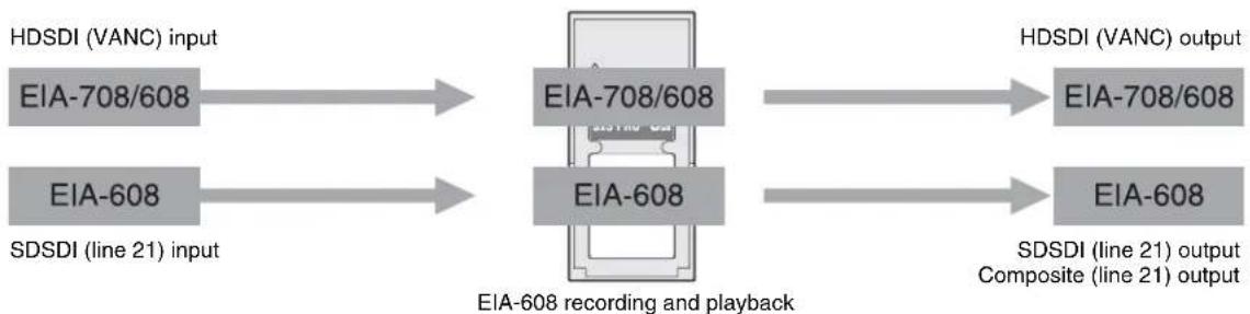
flowchart
graph LR
    A["EIA-708/608"] --> B["EIA-708/608"]
    C["EIA-608"] --> D["EIA-608"]
    B --> E["EIA-708/608"]
    D --> F["EIA-608"]
    G["HDSDI (VANC) input"] --> A
    H["SDSDI (line 21) input"] --> C
    I["HDSDI (VANC) output"] --> E
    J["HDSDI (VANC) output"] --> F
    K["SDSDI (line 21) output Composite (line 21) output"] --> F
EIA-708/608 EE output
In response to closed caption input data that complies with the EIA-708/608 standard, output to EE.
However, settings are required for EE output of closed caption data in HDSDI signals.
For details, see “To record and playback EIA-708-B standard closed caption data in HDSDI signals” (page 116) or “To record EIA-608-B standard closed caption data in HDSDI signals” (page 116).
Closed caption data in SDSDI line 21 signals are output to EE (output as SDSDI or composite signals), regardless of menu settings.
Note
EE output of closed caption data in HDSDI signals is delayed by 1 frame with respect to EE output of the video signals.
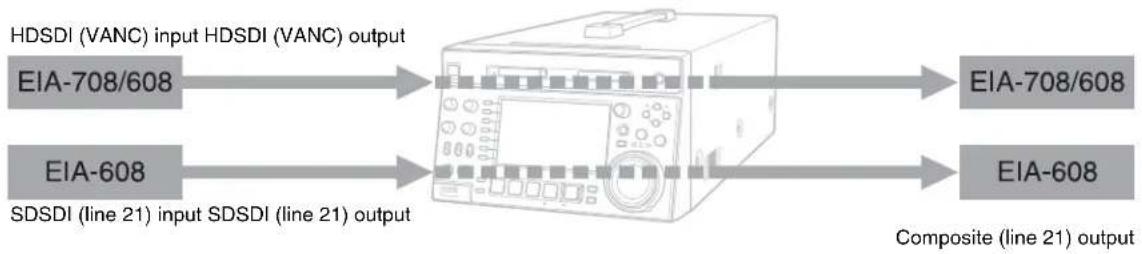
flowchart
graph LR
    A["HDSDI (VANC) input HDSDI (VANC) output"] --> B["EIA-708/608"]
    C["SDSDI (line 21) input SDSDI (line 21) output"] --> D["EIA-608"]
    B --> E["EIA-708/608"]
    D --> F["EIA-608"]
    style A fill:#f9f,stroke:#333
    style C fill:#f9f,stroke:#333
    style B fill:#ccf,stroke:#333
    style D fill:#ccf,stroke:#333
    style E fill:#cfc,stroke:#333
    style F fill:#cfc,stroke:#333
Trademarks and Licenses
Trademarks
- XAVCTM, XAVC logo, MPEG HD422, DVCAM, SxS, SxS PRO, SxS PRO+, SxS PRO X, and SxS-1 are trademarks of Sony Corporation.
- "Memory Stick", Memory Stick PRO-HG Duo" and Maney trademarks of Sony Corporation.
- MPEG HD, HDCAM, and "XOD" are registered trademarks of Sony Corporation.
- The terms HDMI and HDMI High-Definition Multimedia Interface, and the HDMI Logo are trademarks or registered trademarks of HDMI Licensing Administrator, Inc. in the United States and other countries.
- The ExpressCard label and logo are property of the Personal Computer Memory Card International Association (PCMCIA) and are licensed to Sony Corporation. Other trademarks and trade names are the property of their respective owners.
- Adobe, Acrobat, and Adobe Reader are trademarks of Adobe Systems Incorporated in the United States and/or other countries.
MPEG-4 visual patent portfolio license
THIS PRODUCT IS LICENSED UNDER THE MPEG-4 VISUAL PATENT PORTFOLIO LICENSE FOR THE PERSONAL AND NON-COMMERCIAL USE OF A CONSUMER FOR
(i) ENCODING VIDEO IN COMPLIANCE WITH THE MPEG-4 VISUAL STANDARD ("MPEG-4 VIDEO") AND/OR
(ii) DECODING MPEG-4 VIDEO THAT WAS ENCODED BY A CONSUMER ENGAGED IN A PERSONAL AND NON-COMMERCIAL ACTIVITY AND/OR WAS OBTAINED FROM A VIDEO PROVIDER LICENSED BY MPEG LA TO PROVIDE MPEG-4 VIDEO.
NO LICENSE IS GRANTED OR SHALL BE IMPLIED FOR ANY OTHER USE. ADDITIONAL INFORMATION INCLUDING THAT RELATING TO PROMOTIONAL, INTERNAL AND COMMERCIAL USES AND LICENSING MAY BE OBTAINED FROM MPEG LA, LLC. SEE HTTP://WWW.MPEGLA.COM
MPEG LA is offering licenses for (i) manufacturing/sales of any storage media storing MPEG-4 Visual video information (ii) distribution/broadcasting of MPEG-4 Visual video information in any manner (such as online video distribution service, internet broadcasting, TV broadcasting). Other usage of this product may be required to obtain license from
MPEGLA. Please contact MPEG LA for any further information. MPEG LA, L.L.C., 250 STEELE STREET, SUITE 300, DENVER, COLORADO 80206, http://www.mpegla.com
About IJG (Independent JPEG Group)
This software is based in part on the work of the Independent JPEG Group.
Character display software "iType"
This product includes technology from Monotype Imaging Inc., including iType® and certain fonts.
Open source software licenses
On the basis of license contracts between Sony and the software copyright holders, this product uses open software.
To meet the requirements of the software copyright holders, Sony is obligated to inform you of the content of these licenses.
For the content of these licenses, see the PDF files in the "License" folder of the supplied CD-ROM.
Obtaining GPL/LGPL/GPL V3 licensed software
This product uses software licensed under GPL version 2 / LGPL version 2.1 / GPL version 3. You have the right to obtain, change, and distribute the source code of this software.
You can download the source code of this software from Sony Internet servers. Access the following URL, and refer to "XDCAM HD422 Memory Deck Series". https://oss.sony.net/Products/Linux/common/search.html
We cannot respond to inquiries regarding the content of the source code.
Index
A
AC IN connector 20
Accessories
not supplied 112
supplied 112
Alarms 103
Analog
audio signal input/output section 20
ANALOG AUDIO
INPUT 1, 2 connectors 20
OUTPUT 1, 2 connectors 21
Ancillary data 116
Appendix 101
Arrow buttons 12
Audio
input display 15
Audio level
adjustment section 11
meters 15
AUDIO MONITOR R, L connectors
21
B
Basic menu 76
changing settings 80
items 77
operations 80
returning to factory default settings 81
Battery
attaching a battery pack 22
checking the remaining power 23
removing 23
C
CH-1/ALL CH, CH-2 to CH-4
adjustment knobs 11
Chapter thumbnail screen 58
CIFS file operations 75
Clip 65
continuous playback mode 48
copying 52
deleting 63
information 16
locking (write-protecting) 63
properties 57
searching with thumbnails 61
selecting 61
setting clip flags 63
setting the index picture frame 64
single clip playback mode 48
Clip F Menu 60
Clip list screens 55
chapter thumbnail screen 58
details view 56
expand thumbnail screen 58
thumbnails view 56
Clip Menu 59
Clip Properties screen 57
Closed caption data 117
Command list 72
Communications speed 100
COMPOSITE OUTPUT 1, 2 (SUPER)
connectors 20
Connections 25
cut editing system 27
editing control unit settings 28
for pool coverage 31
FTP connection 25
using the editing function of recorder 30
Copying 52
current EDL 65
D
Date and time, setting 25
DC IN 12V connector 20
Digital hours meter 102
display modes 102
displaying 102
exiting 102
DISPLAY
button 13
Display 12, 14
basic operation screen 14
clip list screens 55
switching 55
Display/menu control section 12
E
Editing
control unit 27
controller 29
EDL 65
EDL 65
creating and editing 66
previewing 65
Error messages 109
Essence mark
setting 46,50
Expand
function 7
Expand thumbnail screen 58
Extended menu 76
display 94
items 83
operations 94
External synchronization 32
F
Features 6
File operations 70
directory structure 70
Front panel 10
FTP file operations 71
command list 72
logging in 71
logging out 71
making connections 71
preparations 71
Function buttons (F1 to F6) 12
Function menu 14,37
HOME page 37
P1 INPUT page 38
P3 AUDIO page 38
P4 TC page 39
G
Gigabit Ethernet 7
H
Handle 10
HDMI OUT connector 19
HDSDI OUTPUT 1, 2 (SUPER)
connectors 19
remote control function 47
HOME button 13
|
IN
button 12
indicator 12
Initial Setup 24
J
Jog
mode 50
K
KEY INHI switch 11
L
LEVEL adjustment knob 11
M
Maintenance
periodic 102
MAINTENANCE connector 20
Maintenance menu 95
items 95
network settings 99
operations 98
MARK1/MARK2 buttons 12
Media
properties 68
Media status display 16
MEMORY ACCESS A/B lamps
status indications 41
Memory card slots 11
Menu
bank setting 79
changing settings 80
Clip F Menu 60
Clip Menu 59
configuration 76
function menu 37
Maintenance menu 95
returning to default settings 81
setup menu 76
MENU button 13
Metadata 114
N
Names and functions of parts 10
Network
assigning IP address automatically 99
connector 20
setting IP address 99
settings 99
NEXT button 13
Normal speed playback 49
0
On/standby button and indicator 10
OUT
button 12
indicator 12
P
PAGE button 13
PHONES jack 11
PLAY button 13
Playback 48
EDL 65
jog mode 50
normal speed 49
settings 48
shot mark settings 50
shuttle mode 50
start position 48
variable mode 51
Power supply section 20
POWER switch 20
Preparation
Initial Setup 24
PREV button 13
Proxy AV data 7
PUSH SET knob 13
R
Rear Panel 19
REC button 14
REC INHI indicator 14
Recording 45
HDSDI remote control function
47
level adjustment 46
relay recording 46
salvage 47
settings 45
shot mark settings 46
time 22
Recording and playback control section 13
Recording/playback format 16
REF. VIDEO INPUT connectors 20
Reference signal 15
Relay recording 46
REMOTE connector 20
Remote control switch 11
REMOTE(9P) connector 20
RESET/RETURN button 13
Returning to factory default settings 81
S
Salvage function 47
SD/HDSDI INPUT connector 19
SDSDI OUTPUT 1, 2 (SUPER) connectors 19
Setup menu
basic menu 77
extended menu 83
SHIFT button 13
Shuttle
mode 50
Shuttle/jog/variable control section 12
Specifications 110
Status display 16
Status display area 17
STOP button 13
Sub clip 65
Superimposed text information 35
Supplying power 22
AC power supply 22
Battery power supply 22
DC power supply 22
SxS memory card(s) 40
Synchronization reference signals 32
System frequency setting 33
System information 15
T
Text information 35
Thumbnail search 61
chapter thumbnail screen 62
expand thumbnail screen 61
TIME CODE
IN connector 21
OUT connector 21
Time data display area 16
Timecode 33
after setting initial value 33
input/output section 21
recording external timecode
directly 35
recording sequentially upon the last recorded timecode 34
recording with the internal
timecode generator
synchronized 34
setting to current time 34
Troubleshooting 103
U
UMID Data 114
User bits
setting 34
V
Variable mode 51
VARIABLE switch 11
Video input display 15
The material contained in this manual consists of information that is the property of Sony Corporation and is intended solely for use by the purchasers of the equipment described in this manual.
Sony Corporation expressly prohibits the duplication of any portion of this manual or the use thereof for any purpose other than the operation or maintenance of the equipment described in this manual without the express written permission of Sony Corporation.
PMW-1000
(SYL)
5-019-416-12 (1) © 2013

