mXa-1502 - Mixer Ashly - Free user manual and instructions
Find the device manual for free mXa-1502 Ashly in PDF.


User questions about mXa-1502 Ashly
0 question about this device. Answer the ones you know or ask your own.
Ask a new question about this device
Download the instructions for your Mixer in PDF format for free! Find your manual mXa-1502 - Ashly and take your electronic device back in hand. On this page are published all the documents necessary for the use of your device. mXa-1502 by Ashly.
USER MANUAL mXa-1502 Ashly
Two channel Amplifier
Operating Manual
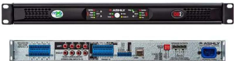
text_image
ASHLY 1502 SHAKED RICHARD INPUTS-1 LEFT RIGHT STREED LINE INPUTS-12 ASTRAL LINE INPUTS-13 ASTRAL LINE INPUTS-14 SPRING OUTPUTS ASHLY PROMPTAINING OUTPUTS
- Click the yellow box on any page to return to the table of contents
- Read these instructions.
- Keep these instructions.
- Heed all warnings.
- Follow all instructions.
- To reduce the risk of fire or electric shock, do not expose this apparatus to rain or moisture.
- Do not use this apparatus near water.
- Clean only with dry cloth.
- Do not block any ventilation openings. Install in accordance with the manufacturer's instructions.
- Do not install near any heat sources such as radiators, heat registers, stoves, or other apparatus.
- Do not defeat the safety purpose of the polarized or groundingtype plug. A polarized plug has two blades with one wider than the other. A grounding type plug has two blades and a third grounding prong. The wide blade or the third prong are provided for your safety. If the provided plug does not fit into your outlet, consult an electrician for replacement of the obsolete outlet.
- Protect the power cord from being walked on or pinched particularly at plugs,
The lightning flash with arrowhead symbol, within an equilateral triangle, is intended to alert the user to the presence of uninsulated "dangerous voltage" within the product's enclosure that may be of sufficient magnitude to constitute a risk of electric shock to persons. The exclamation point within an equilateral triangle is intended to alert the user to the presence of important operating and maintenance instructions in the literature accompanying the device.
convenience receptacles, and the point where they exit from the apparatus.
- Only use attachments/ accessories specified by the manufacturer.
- Use only with the cart, stand, tripod, bracket, or table specified by the manufacturer, or sold with the apparatus. When a cart is used, use caution when moving the cart/ apparatus combination to avoid injury from tip-over.
- Unplug this apparatus during lightning storms or when unused for long periods of time.
- Refer all servicing to qualified service personnel. Servicing is required when the apparatus has been damaged in any way, such as power-supply cord or plug is damaged, liquid has been spilled or objects have fallen into the apparatus, the apparatus has been exposed to rain or moisture, does not operate normally, or has been dropped.
This device complies with part 15 of the FCC Rules. Operation is subject to the following two conditions:
■This device may not cause harmful interference
■This device must accept any interference received, including interference that may cause undesired operation
Note: This equipment has been tested and found to comply with the limits for a Class B digital device, pursuant to part 15 of the FCC Rules. These limits are designed to provide reasonable protection against harmful interference in both a commercial and residential installation. This equipment generates, uses and can radiate radio frequency energy and, if not installed and used in accordance with the instructions, may cause harmful interference to radio communications. However, there is no guarantee that interference will not occur in a particular installation. If this equipment does cause harmful interference to radio or television reception, which can be determined by turning the equipment off and on, the user is encouraged to try to correct the interference by one or more of the following measures:
■Reorient or relocate the receiving antenna.
■ Increase the separation between the equipment and receiver.
■Connect the equipment into an outlet on a circuit different from that to which the receiver is connected.
- Consult the dealer or an experienced radio/TV technician for help.
Unpacking
As a part of our system of quality control, every Ashly product is carefully inspected before leaving the factory to ensure flawless appearance.
After unpacking, please inspect for any physical damage. Save the shipping carton and all packing materials, as they were carefully designed to reduce to a minimum the possibility of transportation damage should the unit again require packing and shipping. In the event that damage has occurred, immediately notify your dealer so that a written claim to cover the damages can be initiated.
The right to any claim against a public carrier can be forfeited if the carrier is not notified promptly and if the shipping carton and packing materials are not available for inspection by the carrier. Save all packing materials until the claim has been settled.
About Ashly
Ashly Audio was founded in 1974 by a group of recording engineers, concert sound professionals, and electronics designers. The first products were elaborate custom consoles for friends and associates, but business quickly spread to new clients and the business grew.
The philosophy we established from the very beginning holds true today: to offer only the highest quality audio tools at an affordable cost to the professional user – ensuring reliability and long life. Years later, Ashly remains committed to these principles.
Ashly's exclusive five-year, worry-free warranty remains one of the most generous policies available on any commercial-grade product. The warranty covers every product with the Ashly brand name, and is offered at no extra cost to you.
Please read this entire manual to fully understand the features and capabilities of this product.

Table of Contents
1 Introduction......
1.1 Product overview......
1.2 Product features......
2 Installation Requirements...
2.1 Electrical and wiring ......
2.2 Mechanical
2.3 Cooling
2.4 Network
2.5 Browser & resolution......
3 Front Panel Features .....
3.1 Mounting holes .....
3.2 Cooling vents ....
3.3 Device reset switch ......
3.4 Channel LEDs ....
3.5 Select buttons ....
3.6 Status LEDs ....
3.7 Power switch ....
3.8 Bridge LED.
4 Rear Panel Features ......
4.1 Mic/line inputs ....
4.2 Stereo line inputs ....
4.3 Aux out 1 & 2 ....
4.4 VCA 1-3 input ....
4.5 Data connection ....
4.6 Trigger 1-8 input ....
4.7 GPO logic outputs 1 & 2 .....
4.8 Amp 1 & 2 fault output .....
4.9 Standby ....
.10 Ethernet port ......
.11 Output mode ....
.12 Speaker outputs ......
.13 AC inlet
.14 Model information ......
5 Network Discovery ......
5.1 Windows 10 ......
5.2 OSX....
5.3 iOS
5.4 ANDROID ......
5.5 What if Discovery Fails? .....
6 AquaControl Software.....
6.1 Dashboard ....
a. Launch quick setup ......
6.2 Signal Chain ....
a. Mic inputs 1-8......
b. Stereo inputs 9-12......
c. Mixers 1-4......
d. Speaker & Aux 1-2 ......
e. Presets....
f. Input DSP
g. Output DSP
DSP blocks....
Audio meter ....
Autoleveler
Brick wall limiter......
Compressor....
DCA gain....
Delay ....
Gain
Gate....
Graphic equalizer......
High-pass filter ....
Low-pass filter ....
Parametric equalizer.....
Signal generator ......
VCA gain....
Ambient noise comp.....
Crossover
FIR filter
h. Mixers/Automixer......
i. Ducking......
j. Routing ....
6.3 Settings....
a. General settings......
Firmware update......
Real time clock......
b. Panels > Front panels .....
Disable power switch.
Disable LEDs......
Sleep mode setup......
Remote power on/off....
Software standby
c. Panels > Front buttons.....
Source select
Preset recall....
Sub-preset recall ......
d. ____ Panels > Rear panels .....
Mic input LEDs ....
Mic phantom pwr ......
Mic gain ....
VCA input status......
Trigger input status.....
Output mode status.
Bridge mode enable.....
Standby pin polarity.....
GPO pin toggle......
e. Network
MAC address
DHCP config ....
Static IP config......
f. Security
Admin
Guest admin ....
Operator
View only ....
6.4 Events......
a. Event list......
b. Scheduled events ......
c. Triggered events .....
6.5 Remotes (software)......
a. Mixers 1-4......
b. DVCA
c. Virtual WR5 ......
d. AquaTouch7....
6.6 Diagnostics......
7 Remote Control (wired) .....
7.1 VCA level control ......
7.2 Trigger logic inputs ......
7.3 GPO logic outputs ......
7.4 Amp fault logic outputs .....
7.5 Remote standby ......
7.6 Ashly remotes ....
a. WR-1.0 and WR-1.1 .....
b. WR-1.5......
c. WR-2
8 Amplifier Protection......
9 Troubleshooting ......
10 Specifications ....
Power amplifier....
AquaControl™ software .....
Dimensions....
mXa-1502 • Operating Manual
1 Introduction
Thank you for your purchase of the mXa-1502 Mixer Amplifier. This product combines state of the art Class D multi-mode amplifier design with eight mic inputs and 4 stereo line inputs for a total of 16 analog inputs.
The mXa-1502 comes standard with comprehensive DSP processing including ducking, matrix mixing, tone generation, integrated Ethernet control using Ashly AquaControl™ software, remote control, triggered/scheduled events, auxiliary outputs, and more. Please read this entire manual to fully understand the features and capabilities of this product.
1.1 Product Overview
The mXa-1502 is a two-channel 150W power amplifier with independently selectable output modes for low impedance (2/4/8 Ohm), 25V,70V, or 100V, plus two AUX line level outputs, each driven by one of four independent mixers. Each mixer front end has access to the same eight quality mic/line inputs and four stereo line inputs.
DSP includes matrix routing and mixing per mixer, ducking, EQ, FiR filter loader, limiter/compressor, noise gate, automixer, autoleveler, ambient noise compensation, crossover, delay, and more. Add to that event scheduler/trigger, remote control, event based logic outputs, fault logic outputs, and more.
The mXa-1502 is configured and controlled using server-based Ashly AquaControl™ software, compatible with most browser enabled devices. AquaControl is served from the mXa-1502, so installing an application on your computer, phone, or tablet is unnecessary.
1.2 Product Features
- Power Amplifier: 2 x 150W, configurable for low-impedance, 25V, 70V, or 100V output
- Inputs: Eight balanced Mic/Line inputs with +48V phantom power, four stereo -10dBV line level inputs using RCA jacks
- Four independent mixers
- Two additional Aux outputs
- Software: Ashly AquaControl server-based software, runs on most web-browsers, no app to install
• Security: Password protected roles for admin, guest admin, operator, or view only
- Presets, sub-presets, & channel templates
- DSP: ducker, automixer, autoleveler, FIR filter, EQ, comp/limiter, delay, crossover, signal generator, ambient noise compensation, more
• Scheduled Events using real-time-clock
- Triggered Events: Eight programmable triggered inputs, two event driven logic outputs
- Compatible with Ashly AquaTouch7 remote
- Two power amplifier fault logic outputs
- Three assignable VCA level control inputs
- Automatic sleep mode, less than 4W, defeatable
- Secure remote control over IP: Virtual WR5, 4 custom remote mixers, 4 DCA groups
• Remote contact closure for power standby
- Front panel LEDs for temp, current, signal, clip, mute, bridge mode, protect, sleep,
Ethernet Com, and power switch disable
• Universal switch mode power supply with active power factor correction (PFC)
- Protection: Shorted output, over-temperature, power supply fault, output DC, mains fuse, in-rush current limiting
• Certifications: FCC, CE, RoHS
- Ashly Five year warranty
2 Installation Requirements
2.1 Electrical and Wiring
The mXa-1502 is designed with a universal power supply, compatible with 100-240VAC, 50-60Hz. Always use the power cord supplied with your unit. Do not remove AC ground.
Always use high quality shielded cable for input signals, and use a balanced input signal when possible. To avoid possible system noise or oscillation, avoid running low level signal wires parallel to speaker outputs or AC wiring, especially over long distance. Before testing the system, double check all connections and settings. Refer to the specifications section of this manual for input, output, Ethernet, and other amplifier properties to consider during installation.
2.2 Mechanical
The mXa-1502 is 1RU, and is designed to fit in a standard 19-inch equipment rack. Use four screws when mounting the amplifier to the front rack rails. Rear support is recommended for mobile or touring use (see mechanical drawing).
mXa-1502 · Operating Manual
2.3 Cooling
Air vents on the front and side panels must have access to free flowing room temperature air. Air is drawn in through the front-right and right-side vent holes and blown out through the front-left vent holes. It is not necessary to leave empty rack spaces above or below the amplifier. See the BTU/hr table in the specifications section for thermal output characteristics.
2.4 Network
The mXa-1502 is compatible with 10MB, 100MB, or 1GB Ethernet. Connect its Ethernet jack to a network switch or router, or connect directly to a computer. A solid yellow LED on the rear panel Ethernet jack indicates a good connection. The green LED blinks to indicate network activity. If there is no LED activity, backtrack through cables, routers, or switches to find the problem. See section 5 for detailed instructions on mXa-1502 network discovery.
2.5 Browser and Resolution
Supported browsers include Chrome, Edge, and Safari. The software requires a minimum screen resolution of 1024 x 768. If using a tablet, a minimum screen size of 10" is recommended.
3 Front Panel Features
3.1 Mounting Holes
For rack mounting. Always use all four screws.
3.2 Cooling Vents
Cool air enters the front-right and right-side vents and is blown out the left front vents.

text_image
3.1 3.2 3.3 3.4 3.5 3.6 3.7 3.8 3.4 1 2 15023.3 Device Reset Switch
There are two levels of device reset, Admin Reset or Factory Default Reset, determined by how long you press and hold this recessed switch during a cold-boot power-up. A cold-boot power-up means AC power is removed before initiating the reset, ie unplugging the AC cord.
To initiate reset, with AC power removed first press and hold the reset switch using a pencil-tip or equivalent, then connect the power cord. During the reset process, all channel LEDs will begin lighting up from bottom to top, followed by the four status LEDs.
To cancel reset before it completes, release the reset switch before the green Signal LEDs turn on.
1) Admin Reset changes the Admin User ID password back to
- To only perform an Admin reset, release the reset switch AFTER the green signal LEDs turn on but BEFORE the Bridge, Protect, Disable, and Sleep LEDs turn on.
2) Factory Default Reset deletes ALL user IDs and passwords, deletes ALL presets, and restores all settings to the factory default. Use this level to completely scrub the device clean of any previous programming.
- To perform a Factory Default Reset, release the reset switch AFTER Bridge, Protect, Disable, and Sleep LEDs turn on.
3.4 Channel LEDs
The red Clip/Mute LEDs flash when output reaches 100% of rated power. Note that there is no clip detector for input levels. This LED also lights solid when the output channel is muted.
The green Signal LEDs light when the output voltage reaches -18dBu below rated output.
The green Current LEDs confirm that amplifier output is being delivered to a speaker load.
The yellow Temp LEDs indicate that the amplifier channel has reached an excessively high operating temperature and will gradually attenuate the signal to compensate. If unable to sufficiently cool the channel, the amplifier will place itself into protect mode.
3.5 Select Buttons
The four select buttons are initially unassigned. They can be programmed in software to perform preset/sub-preset recall or source select. To program select buttons in AquaControl™ software, go to [Settings>Panels>Front Button Settings].
3.6 Status LEDs
Com LED - indicates Ethernet activity, and will also light for 10 seconds after pressing "Identify Device" in the software Settings>Network section.
Protect LED - indicates the amplifier has encountered a fault condition and has shut down its power supply.

mXa-1502 · Operating Manual
Sleep LED - turns on when the amplifier is in sleep mode, configured in software. Set sleep mode on/off plus the desired inactivity time before sleep by going to [Settings>Panels>Front Panel].
Disable LED - is lit whenever the power switch has been disabled from software.
3.7 Power Switch
The power switch turns the unit on or off, and also flashes when in standby. The power switch can be disabled in software. To disable the power switch, go to [Settings>Panels>Front Panel>Enable Front Panel Power Button].
3.8 Bridge LED
This green LED indicates the amplifier has been set to BRIDGE mode from software. To select Bridge mode, go to [Settings>Panels>Rear Panel>Bridge Mode].
4 Rear Panel Features
4.1 Balanced Mic/Line Inputs
Use these for wiring 3-wire balanced inputs (G, +,-) using the provided Euroblock connectors.
If an unbalanced input signal is used, wire its hot signal to (+), its ground to (-), and leave the mXa-1502 input ground pin for that channel unconnected. Maximum input level is +21dBu.
4.2 -10dBV Unbalanced Stereo Line Inputs
These RCA jacks are used for stereo line level inputs (-10dBv). Note: Unbalanced line level sources may reference their outputs to a different ground than this amplifier, creating the potential for ground loop hum. Always use short cable lengths for unbalanced signals,

text_image
BA ANC.D MnO/ N INPUT 51 B 1 2 3 4 5 6 7 8 9 10 11 12 R/GI TUEV UNBA ANC.D S/T W Q IN INPUT 9 13 AUX 01 V 12 V 13 V 14 V 15 V 16 V 17 V 18 V 19 V 20 V 21 V 22 V 23 V 24 V 25 V 26 V 27 V 28 V 29 V 30 V 31 V 32 V 33 V 34 V 35 V 36 V 37 V 38 V 39 V 40 V 41 V 42 V 43 V 44 V 45 V 46 V 47 V 48 V 49 V 50 V 51 V 52 V 53 V 54 V 55 V 56 V 57 V 58 V 59 V 60 V 4.1 4.2 4.3 4.4 4.5 4.7 4.9 4.10 4.11 4.12 4.13 4.6 4.8 SP AKI RQU PU S 2/8/10 OUTPUM MOD 1/2 1/2 SP AKI RQU PU S 2/8/10 SP AKI RQU PU S 2/8/10 SP AKI RQU PU S 2/8/10 SP AKI RQU PU S 2/8/10 SP AKI RQU PU S 2/8/10 SP AKI RQU PU S 2/8/10 SP AKI RQU PU S 2/8/10 SP AK I RQU PU S 2/8/10 SP AKI RQU PU S 2/8/10 SP AKI RQU PU S 2/8/10 SP AKI RQU PU S 2/8/10 SP AKI RQU PU S 2/8/10 SP AKI RQU PU S 2/8/10 SP AKI RQU PUS 2/8/10 SP AKI RQU PUS 2/8/10 SP AKI RQU PUS 2/8/10 SP AKI RQU PUS 2/8/10 SP AKI RQU PUS 2/8/10 SP AKI RQU PUS 2/8/10 SP AKI RQU PUS 2/6/10 SP AKI RQU PUS 2/6/10 SP AKI RQU PUS 2/6/10 SP AKI RQU PUS 2/6/10 SP AKI RQU PUS 2/6/10 SP AKI RQU PUS 2/6/10 SP AKI RQU PUS 2/6/10routed away from AC, video, or data cables, and make every effort to use a common grounding point for all devices. In the event there is still ground loop hum, isolate the unbalanced input signal by using an in-line isolation transformer.
4.3 AUX Out 1 & 2
AUX outputs 1 & 2 provide independent post-DSP signals for driving other amplifiers or processors. AUX outputs are configured in the Signal Chain>Routing section. AUX outputs use balanced signals, maximum output level is +21 dBu.
4.4 VCA 1-3
A VCA (voltage controlled amplifier) is used to remotely control one or more VCA gain blocks placed in any DSP channel's signal chain. Ashly WR-1, WR-1.1, and WR-1.5 remotes can be wired to VCA 1-3 input pins to control the assigned VCA gain. See section 7 for example.
4.5 Data
These four pins for serial data control are inactive, reserved for future remote control devices. No currently available Ashly or third-party remote hardware is compatible with this port.
4.6 Trigger 1-8
Eight contact closure pins can trigger mXa-1502 events or action sequences that have been programmed in software. See section 6.1a, 6.4, or 7.2 for details and available event action types.
4.7 GPO 1 & 2
These pins provide logic outputs referenced to the ground* and +5V* pin found on the same connector. Logic output changes are generated from presets, triggers, or scheduled events, and can be assigned high or low in software. See section 7.3 for example.
4.8 Amp 1 & 2 Fault
Fault output pins are logic-high (+5V*) when the amp channel is on and ok, but transition to logic-low (0V*) when the amp channel is off or in a protect/fault state. See section 7.4 for details.
*For GPO and fault outputs, the +5V pin can source up to 30mA to drive an LED or control system input. The ground pin can sink up to 200mA to provide a ground path for an external relay system.
4.9 Standby
Use a remote switch to place the amp into standby mode by wiring the standby pin to its ground pin. The power switch LED will flash at 1Hz when the amp is in standby mode. Standby pin contact polarity can be set in software for standby when the switch is closed, or standby when open. See section 7.5 for details.
4.10 Ethernet Port
The RJ-45 connects to an Ethernet network or directly to a PC for Ashly AquaControl™ software control.
mXa-1502 • Operating Manual
4.11 Output Mode
This DIP switch independently configures amplifier output channels 1 & 2 for low impedance, 25V, 70V, or 100V output. When the amplifier is set to bridge mode, the channel 1 DIP switch settings determine output mode.
4.12 Speaker Outputs
Use this connector to wire amplifier outputs to speakers or to constant voltage line transformers. The 7.62mmm Euroblock connectors accept up to 12 ga. speaker wire.
4.13 AC Inlet
Used for the detachable AC cord. Use only the factory supplied AC cord. WARNING: Do not remove or lift the AC mains ground connection.
4.14 Model Information
A sticker placed on the side or back of the amplifier shows its serial number, MAC address, plus mains voltage, power, and current specifications.
5 Network Discovery
Before using the software, your device must first recognize and connect with the mXa-1502 through an Ethernet network (DHCP) or via a direct connection to a PC (Link Local). AquaControl uses the default web browser installed on your device. Supported browsers include current versions of Chrome ^® , Edge ^® , and Safari ^® .
Ethernet Connection: The mXa-1502 comes configured with automatic IP assignment as the default. This means you must initially connect its Ethernet jack to a network via a router or other device capable
of automatic IP assignment (DHCP), or alternatively connect it directly to a computer (Link Local).
DHCP: Connect your computer to the same router/LAN that the mXa-1502 Ethernet jack is connected to. Apply power to each device and wait for them to boot up and receive their IP assignments from the router. Wait a couple minutes for the DHCP server to assign IP addresses to each device. Follow the instructions below for your computer or mobile device to discover and connect with the mXa-1502.
Link Local: When the mXa-1502 is configured for Automatic IP, it can be connected directly to a computer.
1) Unplug any network connections from your computer and reboot it. Depending on your computer's configuration, it may be necessary to disable WiFi on your laptop before you re-boot and attempt Link Local connection.
2) Before plugging the mXa-1502 into AC, connect the mXa-1502 Ethernet jack directly to your computer's network jack.
3) Connect AC power to the mXa-1502 and wait approximately two minutes for it to complete the Link Local negotiation.
4) Follow the instructions below for Windows 10 or OSX device discovery. If the computer fails to provide Link Local IP assignment and discovery fails, the mXa-1502 will automatically revert to the IP address 169.254.100.100. In this case, you may need to set your computer's IP address to the same subnet, for example 169.254.100.10, and then type 169.254.100.100 into your web browser address bar to gain access to the device. You can also try to connect using the hostname address, (see 'What to do if discovery fails' on next page).
Getting Started: Use the steps below to initially discover the mXa-1502 based on the device platform you are using. In all cases, the initial default AquaControl login credentials will be:
User ID: "admin"
Password: "secret"
5.1 Windows 10
1) Open the Windows File Explorer (if there is no icon, type "File Explorer" in the bottom left Windows search bar), then in the File Explorer app click on the "Network" section in the left side pane. A list of all connected network devices should begin populating. Wait up to several minutes for the list to complete and skip to step 3. If the list doesn't populate, you may have to right-click in the right side pane and select refresh or enable Windows Network Discovery - see step 2.
2) To enable Windows Network Discovery, click on the yellow warning message at the top of File Explorer's right side pane in the Network section. Repeat Step 1.
3) Your mXa-1502 should appear in the "Other Devices" section of the network list (sometimes referred to as SSDP Plug'N'Play). The mXa-1502's MAC address is added to the end of it's name. The mXa-1502 MAC address is printed on a sticker attached to the mXa-1502 back or side panel. Double-click on the device icon to automatically launch the software. If you still do not see your mXa-1502 listed here, go to step 4, otherwise skip to step 7.
4) In certain cases, your mXa-1502 may appear in the "Computer" section of the network list instead of Other Devices. If this is the case, double-click on it and proceed to step 5.
5) Double-click on the AquaControl shared folder and proceed to step 6.
mXa-1502 • Operating Manual
6) Double-click on the index.html link to launch the software. Proceed to step 7.
7) Log in to AquaControl software. Enter your username and password and press the Log In button. If this is the first log-in to a new unit, use the factory default credentials "admin" for login name and "secret" for password.
5.2 OSX
1) From the desktop, click
2) Find your mXa-1502 in the network device list. The mXa-1502's MAC address is added to the end of it's name. The MAC address is printed on a sticker attached to the mXa-1502 back or side panel. Double-click on the mXa device name.
3) Double click on the resulting
4) Double-click on the resulting
5) Log in to AquaControl software. Enter your username and password and press the Log In button. If this is the first log-in to a new unit, use the factory default credentials "admin" for login name and "secret" for password.
5.3 iOS
1) Use a network device discovery app such as "Flame®" to see all available network devices.
2) Find the mXa-1502 in the list. Its MAC address gets added to the end of its name.
3) Tap on the mXa-1502 device to launch the software. Depending on the app used,
additional address or type lines may need to be entered before the software will launch.
4) Log in to AquaControl software. Enter your username and password, then tap the Log In button. If this is the first log-in to a new unit, use the factory default credentials "admin" for login name and "secret" for password.
5.4 Android
1) Install an Android application that can discover Network Plug'n'Play devices. There are several apps that can do this. For example, "UPnP Tool" is a free discovery app available on the Google Play Store.
2) Launch the UPnP Tool or other network discovery application and it will provide a list of all Plug'n'Play devices on your network. You should see the MXA1502 listed, with its MAC address appended to the name.
3) Click on the (info) information icon, ("i" in a circle), to the right of the item to bring up the details of the product. Then click on the
5.5 What to do if Discovery fails?
1) If using a wired DHCP network connection, and your mXa-1502 still does not appear on the computer's network device list, it may be necessary to disable WiFi on your PC or MAC before initial discovery, and also confirm the computer is truly set for automatic configuration (DHCP).
2) Alternatively, try entering the mXa-1502's unique hostname address in your web browser address bar. The format is: http://MXA1502_(your mac address).local/
Here is a complete example of a unique hostname address:
http://MXA1502_0014AAF00036.local/
DHCP and Static IP: The DHCP server (router), or direct-connected computer may arbitrarily re-assign a new IP address to the mXa-1502 after the IP lease time expires, or whenever the mXa-1502 is rebooted. This could require you to rediscover the mXa-1502 any time its IP address gets reset by the router or computer. To avoid future discovery steps on device reboot, you can assign a Static (permanent) IP address to the mXa-1502 as shown below:
To assign static IP from AquaControl software: Go to [Settings>Network>Network Configuration] and select [Manual Configuration]. Save your settings and note the IP address for future use. Important: If you are using a router, a static IP address reservation for the mXa-1502 must also be entered in your router's IP administration settings. Once the mXa-1502 has been assigned a static IP address, the address can be entered into the browser address bar to connect directly to AquaControl. Important: You must use an IP address with the same subnet as your router and computing device. The subnet is the first three sections of the IP address. For example, 192.168.1 is the subnet section of IP address 192.168.1.100. Tip: The easiest thing to do is use the IP address that was automatically assigned to the mXa-1502 by the router/DHCP server.

mXa-1502 • Operating Manual Ashly AquaControl™ Software
6 AquaControl™ Software
The mXa-1502 uses Ashly's proprietary built-in server based software for setup and control. It is not necessary to install an application onto your computer or mobile device because the program is already resident on the mXa-1502 and runs on your device browser.
The mXa-1502 continues to be enhanced. Please check and update firmware as necessary.
To Update Firmware:
After completing Network Discovery (sec. 5), check the current firmware version by viewing the main software Dashboard page.
Check for the latest firmware on the Ashly website. If a higher version is available, click the link and download the new mXa-1502 [*.bin] file.
To update firmware, go to the [Settings > General Settings] page, then click the "Update" button next to the current firmware revision text. Click the [+ Firmware File] and browse to the new firmware file you just downloaded. Finally, click [Install Update] to begin the update process. The update may take up to 10 minutes to complete and will confirm when finished. Do not remove power from the unit during the update process.
Launch the software and login to your mXa-1502. For new units, the default login credentials are:
User ID: "admin"
Password: "secret"
6.1 Dashboard
text_image
ASHLY Dashboard Signal Chain Settings Events Remotes Diagnostics Logout adminDevice
Device mXa-1502
Inputs 8 Mic/Line Inputs, 4 Stereo Inputs
Outputs 2 Amplifier Outputs, 2 Auxiliary Line
oupo
The dashboard is the first page you see after logging in with your browser. The dashboard shows the Ashly device, number of inputs and outputs, and installed firmware revision.
The other main software pages include:
- Signal Chain: All DSP, Routing, Presets, Templates, Mixers, and Ducking functions are accessed here.
- Settings: All Front & Back Panel, Network, and Security configurations are found here.
• Events: All Scheduled and Triggered Events are created and managed here. - Remotes: All network deployable software Remote Control functions are managed here, including Mixers 1-4, DVCA groups, and Virtual WR5.
• Diagnostics: An exportable log of selected mXa-1502 activity is maintained here for admin or troubleshooting review.
6.1a Launch Quick Setup
From the Dashboard page, launch Quick Setup to easily create new user accounts, set up the network, or program scheduled/triggered events.

Welcome to Ashly AquaControl™ software. You can use Quick Setup to easily get up and running.

Dashboard > Quick Setup
Create account
Network Setup
scheduled Event
Trigpened Event

mXa-1502 • Operating Manual Ashly AquaControl™ Software
6.2 Signal Chain
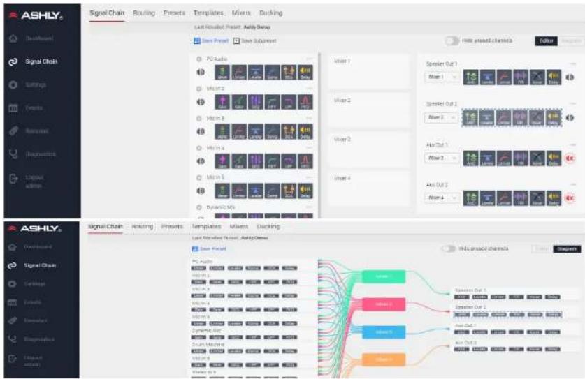
Pluggable DSP blocks get placed and edited here. 16 Input channel are routed to any/all of four mixers, then to the two power amp and/or two aux outputs. The Editor view (top) allows full access to view and edit all Input, Mixer, and Output DSP blocks. Diagram view (bottom) displays routing between all Inputs, Mixer and Outputs (non-interactive), however DSP blocks may still be accessed for editing from this view. In Editor view, every channel has a clickable “*” control for saving or loading a DSP template, copying a DSP chain, or adding mute to a subpreset. Most DSP functions can be linked across channels using one of 16 link groups.
flowchart
graph TD
    subgraph Signal Chain
        direction TB
        A["PS Audio"] --> B["Adder"]
        C["Adder2"] --> D["Adder1"]
        E["Adder3"] --> F["Adder2"]
        G["Adder4"] --> H["Adder1"]
        I["Adder5"] --> J["Adder2"]
        K["Adder6"] --> L["Adder1"]
    end

    subgraph Routing
        M["Switch Pencil"] --> N["Adder"]
        O["Adder1"] --> P["Adder2"]
        Q["Adder3"] --> R["Adder1"]
        S["Adder4"] --> T["Adder2"]
        U["Adder5"] --> V["Adder1"]
    end

    subgraph Outputs
        W["Speaker Out 1"] --> X["Adder 1"]
        Y["Speaker Out 2"] --> Z["Adder 2"]
        AA["Add Out 1"] --> AB["Adder 3"]
        AC["Add Out 2"] --> AD["Adder 4"]
    end

    subgraph Channels
        AE["Signal Channel"] --> AF["Adder"]
        AG["Adder1"] --> AH["Adder2"]
        AI["Adder3"] --> AJ["Adder1"]
        AK["Adder4"] --> AL["Adder2"]
    end

    subgraph Outputs
        AM["Signal Channel"] --> AN["Adder"]
        AO["Signal Chain"] --> AP["Switch Pencil"]
        AQ["Signal Chain"] --> AR["Adder"]
        AS["Signal Chain"] --> AT["Adder1"]
        AU["Signal Chain"] --> AV["Adder2"]
        AW["Signal Chain"] --> AX["Adder3"]
        AY["Signal Chain"] --> AZ["Adder4"]
    end

    style Signal Chain fill:#f9f,stroke:#333
    style Outputs fill:#ccf,stroke:#333
    style Channels fill:#cfc,stroke:#333
    style Outputs fill:#fcc,stroke:#333
    style Channels fill:#cff,stroke:#333
    style Outputs fill:#ffc,stroke:#333
6.2a Mic Inputs 1-8
- Mute/unmute channel, add DSP blocks. Click the gear icon at the upper left corner of each channel to set gain or phantom power. Click the “...” control at upper right corner of any channel for additional copy/subpreset/template functions. See Settings>Panels>Rear Panel.
6.2b Stereo Inputs 9-12
- Mute, DSP, Templates, "..." control settings
6.2c Mixers 1-4
- Set mixer routing, level, ducker and automix status, show/hide chains, add to sub-preset
6.2d Speaker & Aux 1-2 Out
- Source mixer select, DSP, mute, "..." control
6.2e Presets, Subpresets, & Templates
Presets and Sub-Presets get saved to the mXa-1502 for device, scheduled, or triggered recall. Use sub-presets when faster recall of a subset of parameters is desired. Before saving a sub-preset, first select any affiliated DSP functions and select
Note: Recalling a Subpreset will temporarily overwrite Preset settings. When the original preset is recalled, the subpreset settings are canceled.
Templates are files that represent all DSP settings for a single input or output channel, used for quick setup. Ashly has created output templates specifically formulated for our loudspeakers which may include FIR filters and other DSP processing. Download Ashly speaker templates from the Ashly website speaker page.
Templates can also be saved as a snapshot of any input or output channel's current DSP settings. In the Signal Chain Editor view, save or load templates using the "..." control, found on every channel.
6.2f Input DSP blocks
Available DSP functions* for input channels:
- Audio Meter
- Gate
• Autoleveler • Graphic Equalizer - Brick Wall Limiter
- High-Pass Filter
- Compressor
- Low-Pass Filter
- DCA gain
- Parametric Equalizer
- Delay
- Signal Generator
- Gain
- VCA Gain
*Channel 9-12 DSP functions operate in stereo.
6.2g Output DSP blocks
All input DSP blocks are available on output channels, plus the following:
• Ambient Noise Compensation
• Crossover
- FIR Filter
mXa-1502 · Operating Manual
Ashly AquaControl™ Software
DSP Blocks
Audio Meter
The audio meter allows the signal to be monitored at any location in the signal chain. Display range is -60dBu to +20dBu.
Autoleveler
The auto leveler is a dynamics processor used to automatically boost or cut a signal to maintain a user-defined target level.
The target level is the primary setting in the autoleveler, as it determines the constant level to which an input is boost or cut.
The autoleveler can be used in situations such as speech re-enforcement, where an unknown source level needs to be maintained at a specific output level. For example, a podium microphone where different speakers will be presenting may have an auto-leveler applied to ensure that strong or soft speakers' voices are presented at similar output levels.
The controls for the auto leveler are split into two categories, basic and advanced. It is recommended you start with the basic controls, and if fine tuning is required, use the advanced controls.
Warning: Depending on the settings, it is possible to apply up to 27dB of gain with the auto leveler.
Basic Parameters:
bar
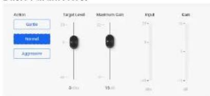
| Action | Target Level | Maximum Gain | Input | | ------ | ------------ | ------------ | ----- | | Gattle | 20 | 20 | 20 | | Normal | 15 | 15 | 15 | | Aggressive | 40 | 40 | 40 |Target Level - This is the desired continuous output level of the signal.
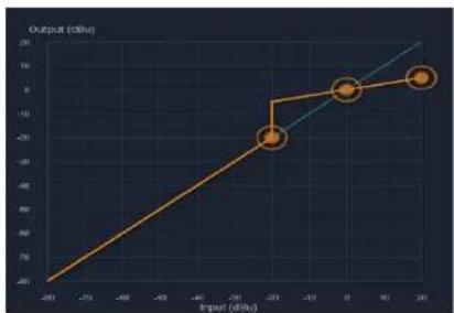
Action - Sets the ratio, hold time, and gain change rates (see table for definitions). These settings are general starting points for how the auto leveler should behave. Action can also be user defined under advanced controls, with three drag points available for a more visual adjustment.
| Action Ratio | Hold Time | Gain Increase | Gain Decrease | |
| Aggressive | 10:15 Seconds | 20 ms/dB | 5 ms/dB | |
| Normal 4:1 | Second | 50 ms/dB | 10 ms/dB | |
| Gentle 2:1 | 2Seconds | 100 ms/dB | 20 ms/dB |
Maximum Gain - This is the total amount of gain the auto leveler may apply before it stops affecting the signal. Maximum gain controls the threshold below target using the following formula:
Threshold Below Target = Max Gain ÷ (1 ÷ ratio) - 1)
Advanced parameters:
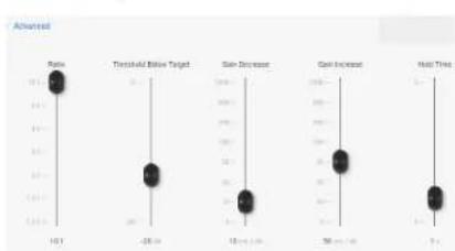
Threshold Below Target - Determines the relative input signal level above which the autoleveler increases gain, below which no action is taken.
Ratio - This is the ratio of the input level change in dB to output level change in dB. It determines the degree of boost or cut applied to a signal to maintain the target level. The higher the ratio, the closer the signal above threshold will approach the target level. However, a higher level also increases how aggressive the autoleveler maintains that gain.
Gain Change Increase/Decrease Rate - Prevents sudden, choppy-sounding level changes to a signal with wide dynamic range.
Hold Time - This is the time after the input signal falls below the threshold during which the autoleveler's gain is held constant before it returns to unity gain. Hold time is used in conjunction with gain change rate to arrive at a natural-sounding auto leveler action.
Both the advanced and basic control views have a visible meter bar. It shows the gain or attenuation applied by the auto leveler in 1 dB steps.
line
| Input (dBu) | Output (dBu) | |---|---| | -20 | -20 | | -15 | -15 | | -10 | -10 | | -5 | -5 | | 0 | 0 | | 5 | 5 | | 10 | 10 | | 15 | 15 | | 20 | 20 |mXa-1502 • Operating Manual Ashly AquaControl™ Software
Brick Wall Limiter Parameters:
scatter
| Event | Value | | --------- | ----- | | Threshold | 0.5 | | Ratio | 0 | | Infinite | 0 | | Attack | 0.5 | | Release | 100 |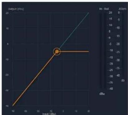
line
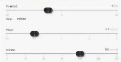
| Input (dBu) | Output (dBu) | |-------------|--------------| | -10 | -40 | | 0 | 0 | | 20 | 20 |The brick wall limiter is a compressor with a fixed infinite ratio. Use this limiter to prevent signal from exceeding a designated peak level. The limiter has threshold, attack time and release time adjustments.
For a more natural sounding gain reduction that allows some signal above threshold, use the compressor.
Threshold - The signal level at which the limiter begins to apply gain reduction to the signal. Threshold range is -20dBu to +20dBu.
Ratio - There is no ratio control, ratio is fixed at infinite, no signal increase above threshold.
Attack Time - The rate in mS/dB that gain reduction occurs after the signal level crosses threshold.
Release Time - The rate in mS/dB that gain reduction activity stops after the signal level drops back below threshold.
Detector Type - The detector type for the brick wall limiter is set to peak detect only.
Compressor
The compressor function offers adjustable threshold, ratio, attack time, release time, plus selection of either peak or average detector.
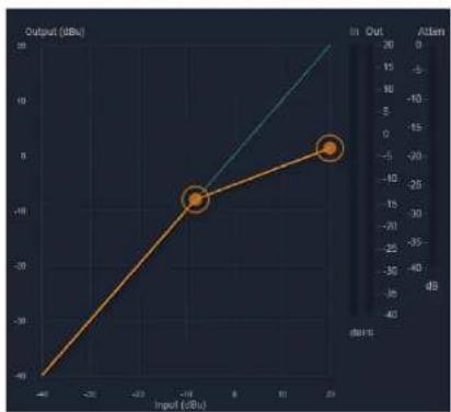
line
| Input (dBu) | Output (dBu) | |-------------|--------------| | -10 | -40 | | 0 | -20 |Up to four attenuation bus assignments are also offered, allowing multiple compressor blocks to track together, ie for stereo signals.
Parameters:
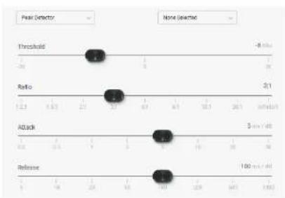
scatter
| Metric | Value | |--------|-------| | Threshold | -8.00 | | Ratio | 3.11 | | Attack | 5.00 | | Release | 100.00 |Threshold - The signal level at which the compressor begins to apply gain reduction to the signal. Threshold range is -20dBu to +20dBu.
Ratio - The amount of gain reduction applied to signal level above threshold. Range is 1.2:1 to infinite.
Attack Time - The rate in mS/dB that gain reduction occurs after the signal level crosses threshold.
Release Time - The rate in mS/dB that gain reduction activity stops after the signal level drops back below threshold.
Attenuation Bus 1-4 - All compressors assigned to the same attenuation bus will apply the largest amount of gain reduction from any one of the assigned compressors. This is typically used for tracking compression across stereo signals.

mXa-1502 • Operating Manual Ashly AquaControl™ Software
Detector Type - This selects between peak or average detector operation:
- Peak Detector - Setting the detector type as peak means that only the peak level of a signal is used to trigger the compressor. Peak detect is typically used for limiter applications where any signal level above a certain point is undesirable.
- Average Detector - Setting the detector type to average means that a computed average signal level is used instead of peak levels. The averaging detector is more musical and natural sounding and typically used to "thicken" vocals.
DCA Gain
scatter
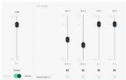
| Year | Normal | Normal | |------|--------|--------| | 2014 | 63 | 40 | | 2015 | 63 | 40 | | 2016 | 63 | 40 | | 2017 | 63 | 40 |A DCA gain block can be placed on any channel in order to make that channel available for DCA groups 1-4. Each DCA block must be turned ON to be active. Each DCA block must also be enabled for its targeted DCA group.
There is a level to trim the gain of the channel, which gets combined with any DCA fader levels enabled for the channel.
A DCA is typically set up and deployed to a remote operator who has limited access but still needs to control a zone's overall volume via mobile device or tablet. See section 6.1b for deploying a DCA to a remote control operator.
DCA Gain Parameters:
Overall Level to DCA: Off, -50dB to +12dB
Polarity: Normal, Inverted
DCA 1-4 Level: Off, -50dB to +12dB in 0.1dB increments
DCA 1-4 Enable: On, Off
Delay
text_image
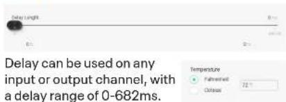
Delay length 0-682ms Delay can be used on any input or output channel, with a delay range of 0-682ms.Delay can be set by time or distance using a scroll bar, or set manually by entering a numerical value. Ambient air temperature can be entered to adjust for changes to the speed of sound through hotter or colder air.

mXa-1502 • Operating Manual Ashly AquaControl™ Software
Gain

The gain block allows the user to modify a signal's level by either applying gain or attenuation. The polarity of the
signal may also be inverted. The level control allows for gain adjustment between +12db and -50dB and OFF. The level fader can be adjusted in 0.1dB increments.
Note: A gain control must be placed if using a gain increment/decrement event (sec 6.4).
Gain Parameters:
Level: Off, -50dB to +12dB in 0.1dB increments
Polarity: Normal or inverted
Gate
scatter
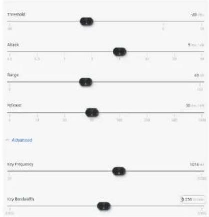
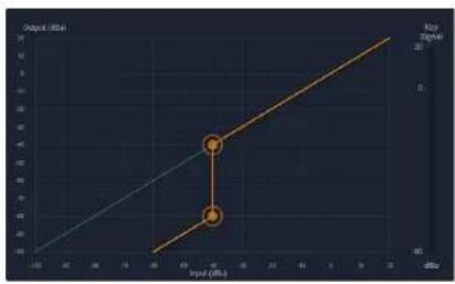
| Metric | Value | | --------------- | ----- | | Threshold | 48 | | Attack | 5 | | Range | 49 | | Release | 50 | | Advanced | 1016 | | Key Frequency | 3 | | Key Bandwidth | 276 |A noise gate can be used to minimize unwanted, low level ambient sounds from getting through on an individual input channel. Threshold is the level above which an input signal will pass through, below which its signal is attenuated by the range value. Attack and release controls set the time characteristics of the gating action. Attack sets the amount of time used to ramp up the gain to unity. Release sets the time required to attenuate the signal. The gate may be assigned to a link group to link its parameters with other channel gates.
Gate Parameters:
Threshold: The minimum input signal level (also called key signal) required to open the noise gate and allow signal to pass through. Threshold can be set using the slide fader, text entry box, or a drag point on the graph.
Attack: The rate at which input signal level rises up to unity gain after reaching the gate threshold.
Range: The amount of attenuation applied to the gated signal when it remains below threshold, sometimes referred to as "floor".
Release: The rate at which attenuation is applied to the signal after it falls back below gate threshold.
line
| Input (dB) | Output (dB) | |---|---| | 0 | 0 | | 1 | 1 | | 2 | 2 | | 3 | 3 | | 4 | 4 | | 5 | 5 | | 6 | 6 | | 7 | 7 | | 8 | 8 | | 9 | 9 | | 10 | 10 | | 11 | 11 | | 12 | 12 | | 13 | 13 | | 14 | 14 | | 15 | 15 | | 16 | 16 | | 17 | 17 | | 18 | 18 | | 19 | 19 | | 20 | 20 | | 21 | 21 | | 22 | 22 | | 23 | 23 | | 24 | 24 | | 25 | 25 | | 26 | 26 | | 27 | 27 | | 28 | 28 | | 29 | 29 | | 30 | 30 | | 31 | 31 | | 32 | 32 | | 33 | 33 | | 34 | 34 | | 35 | 35 | | 36 | 36 | | 37 | 37 | | 38 | 38 | | 39 | 39 | | 40 | 40 | | 41 | 41 | | 42 | 42 | | 43 | 43 | | 44 | 44 | | 45 | 45 | | 46 | 46 | | 47 | 47 | | 48 | 48 | | 49 | 49 | | 50 | 50 | | 51 | 51 | | 52 | 52 | | 53 | 53 | | 54 | 54 | | 55 | 55 | | 56 | 56 | | 57 | 57 | | 58 | 58 | | 59 | 59 | | 60 | 60 | | 61 | 61 | | 62 | 62 | | 63 | 63 | | 64 | 64 | | 65 | 65 | | 66 | 66 | | 67 | 67 | | 68 | 68 | | 69 | 69 | | 70 | 70 | | 71 | 71 | | 72 | 72 | | 73 | 73 | | 74 | 74 | | 75 | 75 | | 76 | 76 | | 77 | 77 | | 78 | 78 | | 79 | 79 | | 80 | 80 | | Note: The output values are estimated based on the input values. The chart displays a step function with a step size of -1. The x-axis represents Input (dB) and the y-axis represents Output (dB). There is no label for the data series. The labels 'Output (dB)' appear to be the same as the input values, but they are not explicitly labeled in the chart.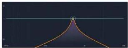
line
| x | y | | ---- | ----- | | 0 | 10.0 | | 10 | 8.0 | | 20 | 6.0 | | 30 | 4.0 | | 40 | 2.0 | | 50 | 1.0 | | 60 | 0.5 | | 70 | 0.2 | | 80 | 0.1 | | 90 | 0.05 | | 100 | 0.02 | | 110 | 0.01 | | 120 | 0.005 | | 130 | 0.002 | | 140 | 0.001 | | 150 | 0.0005| | 160 | 0.0002| | 170 | 0.0001| | 180 | 0.00005| | 190 | 0.00002| | 200 | 0.00001| | 210 | 0.000005| | 220 | 0.000002| | 230 | 0.000001| | 240 | 0.0000005| | 250 | 0.0000002| | 260 | 0.0000001| | 270 | 0.00000005| | 280 | 0.00000002| | 290 | 0.00000001| | 300 | 0.000000005| | 310 | 0.000000002| | 320 | 0.000000001| | 330 | 0.0000000005| | 340 | 0.0000000002| | 350 | 0.0000000001| | 360 | 0.0 | | 370 | 1.5 | | 380 | 3.5 | | 390 | 5.5 | | 400 | 7.5 | | 410 | 9.5 | | 420 | 11.5 | | 430 | 13.5 | | 440 | 15.5 | | 450 | 17.5 | | 460 | 19.5 | | 470 | 21.5 | | 480 | 23.5 | | 490 | 25.5 | | 500 | 27.5 | | Note: The y-values are estimated based on the provided code format (e.g., 'x' is not explicitly labeled). The x-axis label is 'x' and the y-axis label is 'y'. There is no additional data series or legend specified in the code.Advanced Mode Parameters:
Advanced mode allows the user to employ a key filter for the gate. A key filter does not EQ the signal passing though the gate, but rather allows the gate threshold detector to respond only to a frequency band (pass-band) within the signal as determined by the filter. The key filter is a band-pass filter with selectable center frequency and bandwidth.
Key Frequency: This is the center frequency of the key filter.
Key Bandwidth: This sets the bandwidth used for the key filter, and is always on. The default bandwidth setting is a very wide 15 octaves, and as such has no frequency-specific effect.
To use frequency selective key threshold detection, adjust the key bandwidth to a lower setting and set the frequency and bandwidth as desired.

mXa-1502 • Operating Manual Ashly AquaControl™ Software
Graphic Equalizer

line
| Year | Gross Profit | |------|--------------| | 2024E | 11.0 | | 2025 | 11.5 | | 2026 | 11.3 | | 2027 | 11.8 | | 2028 | 11.6 | | 2029 | 11.4 | | 2030 | 10.8 | | 2031 | 9.5 | | 2032 | 8.0 | | 2033 | 6.5 | | 2034 | 5.0 | | 2035 | 4.5 | | 2036 | 4.0 | | 2037 | 3.5 | | 2038 | 3.0 | | 2039 | 2.5 | | 2040 | 2.0 | | 2041 | 1.5 | | 2042 | 1.0 | | 2043 | 0.5 | | 2044 | 0.0 | | 2045 | -0.5 | | 2046 | -1.0 | | 2047 | -1.5 | | 2048 | -2.0 | | 2049 | -2.5 | | 2050 | -3.0 | | 2051 | -3.5 | | 2052 | -4.0 | | 2053 | -4.5 | | 2054 | -5.0 | | 2055 | -5.5 | | 2056 | -6.0 | | 2057 | -6.5 | | 2058 | -7.0 | | 2059 | -7.5 | | 2060 | -8.0 | | 2061 | -8.5 | | 2062 | -9.0 | | 2063 | -9.5 | | 2064 | -10.0 | | 2065 | -10.5 | | 2066 | -11.0 | | 2067 | -11.5 | | 2068 | -12.0 | | 2069 | -11.8 | | 2070 | -11.6 | | 2071 | -11.4 | | 2072 | -11.2 | | 2073 | -11.0 | | 2074 | -10.8 | | 2075 | -10.6 | | 2076 | -10.4 | | 2077 | -10.2 | | 2078 | -10.0 | | 2079 | -9.8 | | 2080 | -9.6 | | 2081 | -9.4 | | 2082 | -9.2 | | 2083 | -9.0 | | 2084 | -8.8 | | 2085 | -8.6 | | 2086 | -8.4 | | 2087 | -8.2 | | 2088 | -8.0 | | 2089 | -7.8 | | 2090 | -7.6 | | 2091 | -7.4 | | 2092 | -7.2 | | 2093 | -7.0 | | 2094 | -6.8 | | 2095 | -6.6 | | 2096 | -6.4 | | 2097 | -6.2 | | 2098 | -6.0 | | 2099 | -5.8 | | 2100 | -5.6 | | 2101 | -5.4 | | 2102 | -5.2 | | 2103 | -5.0 | | 2104 | -4.8 | | 2105 | -4.6 | | 2106 | -4.4 | | 2107 | -4.2 | | 2108 | -4.0 | | 2109 | -3.8 | | 2110 | -3.6 | | 2111 | -3.4 | | 2112 | -3.2 | | 2113 | -3.0 | | 2114 | -2.8 | | 2115 | -2.6 | | 2116 | -2.4 | | 2117 | -2.2 | | 2118 | -2.0 | | 2119 | -1.8 | | 2120 | -1.6 | | 2121 | -1.4 | | 2122 | -1.2 | | 2123 | -1.0 | | 2124 | -0.8 | | 2125 | -0.6 | | 2126 | -0.4 | | 2127 | -0.2 | | 2128 | 0.0 | | 2129 | 0.2 | | 2130 | 0.4 | | 2131 | 0.6 | | 2132 | 0.8 | | 2133 | 1.0 | | 2134 | 1.2 | | 2135 | 1.4 | | 2136 | 1.6 | | 2137 | 1.8 | | 2138 | 2.0 | | 2139 | 2.2 | | 2140 | 2.4 | | 2141 | 2.6 | | 2142 | 2.8 | | 2143 | 3.0 | | 2144 | 3.2 | | 2145 | 3.4 | | 2146 | 3.6 | | 2147 | 3.8 | | 2148 | 4.0 | | 2149 | 4.2 | | 2150 | 4.4 | | 2151 | 4.6 | | 2152 | 4.8 | | 2153 | 5.0 | | 2154 | 5.2 | | 2155 | 5.4 | | 2156 | 5.6 | | 2157 | 5.8 | | 2158 | 6.0 | | 2159 | 6.2 | | 2160 | 6.4 | | 2161 | 6.6 | | 2162 | 6.8 | | 2163 | 7.0 | | 2164 | 7.2 | | 2165 | 7.4 | | 2166 | 7.6 | | 2167 | 7.8 | | 2168 | 8.0 | | 2169 | 8.2 | | 2170 | 8.4 | | 2171 | 8.6 | | 2172 | 8.8 | | 2173 | 9.0 | | 2174 | 9.2 | | 2175 | 9.4 | | 2176 | 9.6 | | 2177 | 9.8 | | 2178 | 10.0 | | Note: The actual values for 'Gross Profit' are not provided in the code provided in the image file format.The graphic equalizer offers 31 standard ISO center frequency controls with constant Q or proportional Q filters, as well as adjustable filter bandwidth.
GEQ Parameters:
Faders: Graphic representation of the 31 EQ filter controls. Adjust faders one at a time, or drag across any region of the graph to adjust faders.
To return all GEQ faders to their "0" setting, click or tap the "Flatten" button in the upper left corner of the graphic display.
Filter Type: This selects constant Q (default) or proportional Q filters.
- Constant Q filters have consistent Q/ bandwidth regardless of the amount of boost or cut.
• Proportional Q filters get narrower with increasing boost/cut.
Differences in filter shapes can be observed on the frequency response display.
Bandwidth: The default bandwidth is 1/3 octave. All filters can be changed together to use a bandwidth from 1/4 octave to 1/2 octave.
High-Pass Filter

natural_image
Abstract gradient background with purple and teal color blocks (no text or symbols)A high-pass filter (HPF) is a single ended filter without a level control, passing only signal above the selected corner frequency. Filter types include Bessel, Butterworth, Linkwitz, and Linkwitz Notch, offering a variety of filter slope values.
HPF Parameters: filter type, frequency
Low-Pass Filter
natural_image
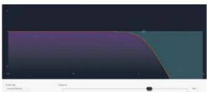
Abstract gradient background with purple and teal color blocks, no text or symbols presentA low-pass filter (LPF) is a single ended filter without a level control, passing only signal below the selected corner frequency. Filter types include Bessel, Butterworth, Linkwitz, and Linkwitz Notch, offering a variety of filter slope values.
LPF Parameters: filter type, frequency

mXa-1502 • Operating Manual Ashly AquaControl™ Software
Parametric Equalizer
line
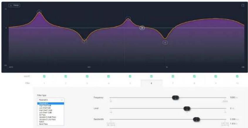
| Time | Value | |------|-------| | 0 | 0 | | 1 | 0 | | 2 | 0 | | 3 | 0 | | 4 | 0 | | 5 | 0 | | 6 | 0 | | 7 | 0 | | 8 | 0 | | 9 | 0 | | 10 | 0 | | 11 | 0 | | 12 | 0 | | 13 | 0 | | 14 | 0 | | 15 | 0 | | 16 | 0 | | 17 | 0 | | 18 | 0 |The PEQ parametric equalizer offers a variety of useful filter types for adjusting signal response with greater precision. A master on/off button enables/disables the PEQ block.
10 individual filters are available per PEQ block, each filter capable of the following types: Parametric, high-shelf and low-shelf at 6dB/octave or 12dB/octave, all-pass, variable-Q high-pass and low-pass, notch, and band-pass. Individual filters have an on/off setting.
Select a filter number first, then choose a filter type, then adjust by dragging its control node, using the slide-controls, or by entering parameter values in the text boxes to the right of each control.
PEQ Parameters:
Filter 1-10: filter On/Off, active selection
Filter Types:
- Parametric: Symmetric boost/cut, allowing individual adjustment of center frequency, level and bandwidth.
- High-Shelf: Asymmetric boost or cut with "shelving" shape. Allows adjustment of the corner frequency and amplitude. Slope can be selected as 6 dB/octave or 12 dB/octave.
- Low-Shelf: Mirror-image of high-shelf.
- All Pass: Provides no change in amplitude, but adds -180° phase shift at the corner frequency.
- Notch: Infinite cut at specified center frequency, with adjustable bandwidth or Q.
-
Variable Q HPF: Second order high pass filter with adjustable Q.
-
Variable Q LPF: Second order low pass filter with adjustable Q.
- Band Pass: This will pass signals within the filter's response region. It allows adjustment of center frequency and bandwidth/Q. Gain is 0 dB at the center frequency.
Frequency: Selected filter center/corner frequency.
Level: Selected filter boost/cut amplitude.
Bandwidth: Selected filter bandwidth (or Q).
Filter Type Details
Parametric EQ Filters
Parametric EQ uses peak filters with the ability to control boost or cut, frequency center, and bandwidth. Think of one band of parametric EQ as a single graphic equalizer fader, except that the frequency is variable, and the bandwidth, or how "wide" the filter affects the frequency spectrum at the center frequency, is also variable. The smaller the bandwidth, the less the audio signal on either side of the frequency center is boost or cut, whereas a larger "wider" bandwidth produces an audible change to the overall tone of a signal.
Parametric filters are best used to hunt down and eliminate problem feedback frequencies, add or remove a characteristic "hot spot" from microphones, or clean up room resonance situations. It is well worth the time becoming proficient with parametric EQ filters, as they offer the best solution to many EQ problems.
Parametric filters have a boost/cut range of +15dB to -30dB. There is more cut than boost because one of the more common uses for parametric filters is to dramatically cut, or "notch out", very narrow frequencies

mXa-1502 • Operating Manual Ashly AquaControl™ Software
(low bandwidth) in order to eliminate system feedback problems.
Every instance of a parametric EQ filter has a center frequency selected. Each filter's center frequency is adjustable from 20Hz to 20kHz in 1/96 octave steps. Carefully sweeping a narrow bandwidth filter through a problem feedback area, with just a slight boost, is a quick way to find the exact frequency causing trouble. Once the offensive frequency has been found, cut the filter's level, and the adjust the bandwidth as narrow as possible while still eliminating the feedback problem.
Bandwidth is adjustable from about 1/64 octave to four octaves, and the lower the bandwidth, the less audible the filter action will be. Finding the problem frequency is relatively easy, but finding the best combination of cut and bandwidth takes a little practice. Again it is well worth the time getting comfortable with the notching procedure, so that problems can be quickly addressed with a sufficient but minimal amount of correction.
Shelving EQ Filters
1st order filters use a gentle 6dB per octave slope, while 2nd order filters use a 12dB per octave slope for a more pronounced boost or cut. All shelving filters have a boost/cut range of +/- 15dB and frequency range from 20Hz through 20kHz. Shelving filters are most useful as broad tone controls to boost or cut the high end or low end of an audio signal's frequency content. Because they affect a wider spectrum of audio, they are not as suitable for feedback control as parametric filters.
All-Pass Filters
The all-pass option is a 2nd order all-pass filter which provides a -180° phase shift at the corner frequency. At very high frequencies the phase delay approaches -360°. All-pass filters may be used to add frequency dependent phase shift or phase delay to the audio signal path. It does not produce a measurable effect on the magnitude response of the signal.
Signal Generator
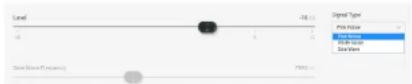
The signal generator creates pink noise, white noise or a sine wave output.
When a signal generator is placed in an input signal chain and turned on, audio input for that channel becomes disabled.
When placed in an output signal chain and turned on, the mixer signal routed to that output becomes disabled.
White noise is randomly generated broadband noise.
Pink noise is bandwidth-limited from 20Hz - 20kHz to contain equal energy in any octave (-6 dB per octave low-pass filtered).
The sine wave has adjustable frequency. All three signal types can be generated at any level from -50dBu to +20dBu.
Signal Generator Parameters
Signal Type: Pink noise, white noise, or sine wave
Frequency: Frequency of signal to be generated (sine wave only).
Level: RMS level of signal generated.
Bypass: Turns off generated signal and allows audio signal to pass through.
VCA Gain
text_image
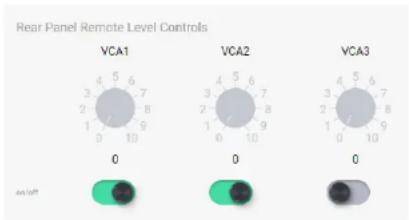
Rear Panel Remote Level Controls VCA1 VCA2 VCA3 0 0 0Three back-panel VCA (voltage controlled amplifier) input pins are used to remotely control the level of assigned inputs or outputs using a simple potentiometer circuit.
In order to use VCA inputs, one or more VCA gain blocks must first be placed in the signal chain, then assigned to VCA inputs 1-3. A single VCA input pin on the back panel can be control multiple VCA Gain blocks.
The three VCA inputs can be enabled or disabled, and saved in a preset or sub-preset.
Use an Ashly WR-1 remote or equivalent to send a variable DC voltage to any of the three VCA pins.
The current position of any connected potentiometer is shown in software in the Settings>Panels>Rear Panel page.
See sec. 4.4 or section 7.1 for more details.

mXa-1502 • Operating Manual Ashly AquaControl™ Software
Ambient Noise Compensation - ANC (output channels only)
scatter
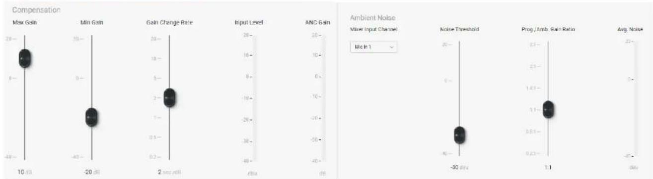
| Metric | Value | |--------|-------| | Max Gain | 10 dA | | Min Gain | -20 dA | | Gain Change Rate | 2 sec roll | | Input Level | dBm | | ANC Gain | dBm | | Noise Threshold | -30 dBm | | Prog./Amb. Gain Ratio | 1.1 dBm | | Avg. Noise | dBm |Ambient noise compensation (ANC) is an automatic output level control that uses a microphone monitoring a zone's ambient background noise to adjust overall output level for that zone, automatically maintaining intelligibility above the ambient noise.
Note: The ambient sensing microphone input can not be routed to the zone's mixer.
The ambient noise sensing mic is processed similar to a slow-responding SPL meter, which is then used as the control signal for the automatic level control of the program audio.
The ambient sensing microphone doesn't need to be a high-quality microphone. It is only used to detect the overall noise level in the zone and is not used for the direct program audio or paging.
The placement location of the noise-detecting microphone is very important for the ambient noise compensation function to work well. A unidirectional microphone pointed toward
the noise sources but away from any speakers works best.
ANC Parameters:
Max Gain: This sets the maximum gain the ANC can apply to the program audio. A typical starting value is 10 dB.
Min Gain: This sets the base level of the program audio before any ANC action affects it. When the noise detecting mic exceeds the noise threshold, ANC applies gain above the minimum gain setting according to the Program/Ambient Gain Ratio setting. A typical starting value for minimum gain is -20 dB.
Gain Change Rate: This is the rate at which the ANC will increase the gain, measured in seconds per dB. A typical starting value is 2 seconds/dB.
Input Level Meter: This indicates the level of the program audio before any ANC gain or attenuation is applied.
ANC Gain Meter: This shows the current gain or attenuation being applied to the program audio by the ANC function.
ANC Mixer Input Channel: This selects the mic input channel used for ambient noise sensing. The mic signal is taken post-input DSP. The mic must not be routed to the ANC zone.
Noise Threshold: This sets the ambient noise mic level above which the ANC will begin increasing the program audio gain above the minimum gain setting. A typical starting value is -30 dBu. Keep in mind that any changes to the noise-sensing microphone gain will affect the action of the noise threshold control.
Program/Ambient Gain Ratio: This sets the ratio of dB increase in program level for every 1 dB increase in ambient noise level. A typical starting value is 1.0 which means that for every 1 dB increase in ambient noise above the threshold, the ANC will increase the gain of the program audio by 1 dB.

mXa-1502 • Operating Manual Ashly AquaControl™ Software
Average Noise Meter: This meter indicates the averaged level of the ambient noise sensing microphone.
ANC Setup Procedure
- In software, place an ANC block on the output channel to be used for background music or voice paging in that zone.
- Open the ANC block to edit its control window. Set the ANC controls to the typical settings described above, which are the default settings of a new ANC block when it is first placed.
- Turn the ANC function ON.
- Select the noise-sensing microphone input from the drop-down box labeled "Mixer Input Channel". Make sure the mic is not routed to the output channel using ANC.
- Physically locate the noise-sensing microphone in the zone by pointing it toward the primary noise sources such as groups of people, HVAC equipment, vehicle traffic etc, but pointed away from the sound system speakers or their direct reflections.
-
Add appropriate mic preamp gain to the ambient-sensing mic channel, add gain, EQ, HPF or LPF, compression, or even a noise gate if desired. The noise-sensing microphone signal will appear on the Average Noise input level meter. To set up ANC controls for effective operation without ambient noise sources present, a pink noise source or even a portable stereo can be placed near the expected ambient noise source to simulate anticipated volumes.
-
Beginning at -40dBu, adjust the Noise Threshold control to respond to the average noise input level above which point you want the program audio to begin increasing.
- Increase the zone noise source volume until you see the average noise meter rise above your noise threshold setting. You should begin to see the ANC Gain meter slowly rise above the minimum gain setting.
- Slowly increase the noise source further and adjust the program/ambient gain ratio for the desired amount of noise compensation.
- Continue to increase the noise source volume to the highest anticipated level. Adjust the max gain to a level which limits the maximum gain that the ANC applies to the program audio so it will not become too loud or clip.
- The gain change rate can be adjusted according to how fast you would like the gain increase to occur in response to increases in ambient noise.
- Be aware that an improperly setup ANC can result in runaway gain where the program audio is picked-up by the noise-sensing microphone as background noise. The result is not necessarily feedback squeals, but the gain of the program audio could ramp up to the max gain value even with no ambient room noise. The best remedy for this problem is to locate the noise-sensing microphone closer to the expected noise sources and further away from the sound system speakers or their reflections. A baffle can be constructed between the speaker and microphone to block direct or reflected sound pickup. Also, the Program/Ambient Gain Ratio can be lowered to reduce the susceptibility to gain runaway.

mXa-1502 • Operating Manual Ashly AquaControl™ Software
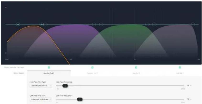
Crossover (output channels only)
text_image
User-Disorder On Graph Select Output Speaker Out 1 Speaker Out 2 Ave Out 1 Ave Out 2 High Pass Filter Type University of School High Pass Frequency 30 Hz 20000 Low Pass Filter Type Bullworth Shift/Drive Low Pass Frequency 70 HzCrossover blocks can be placed on both speaker and Aux output channels. A high-pass and low-pass filter type and frequency get applied to each crossover block to band-limit the signal for that output.
All outputs populated with a crossover block are shown combined on screen for clear visual representation of crossover settings. Select any of the four outputs to edit their filter parameters.
Filter types can be selected to match the acoustic response of your loudspeaker system. Consult the loudspeaker manufacturer for their recommended crossover filter types and frequencies.
Available Filter Types:
Butterworth: Butterworth filters have a maximally flat magnitude response and sharpest transition to the stop-band, and are available in 1st through 8th order filters (6, 12, 18, 24, 30, 36, 42, 48dB/octave).
Linkwitz: Linkwitz-Riley filters exhibit flat combined on-axis magnitude response, and are available in 2nd, 4th, 6th, and 8th order filters(12, 24, 36, 48dB/octave).
Bessel: Bessel filters have a maximally flat phase response, and are available in 2nd, 3rd, 4th, 5th, 6th, 7th, and 8th order filters (12, 18, 24, 30, 36, 42, 48dB/octave).
Linkwitz Notch: Linkwitz-Notch filters exhibit fast rolloff with ripple in the stopband, and have flat combined on-axis magnitude response. They are available as 4th and 8th order (24, 48dB/octave).
| Filter Type Order | Combined Response at Crossover Frequency (dB) Polarity | ||
| Butterworth 1st 0.0 | norma | ||
| 2nd 3.0 | *inverted | ||
| 3rd 0.0 | normal | ||
| 4th 3.0 | normal | ||
| 5th 0.0 | normal | ||
| 6th 3.0 | *inverted | ||
| 7th 0.0 | normal | ||
| 8th 3.0 | normal | ||
| Linkwitz 2nd 0.0 | *inverted | ||
| 4th 0.0 | normal | ||
| 6th 0.0 | *inverted | ||
| 8th 0.0 | normal | ||
| Bessel 2nd 2.7 | *inverted | ||
| 3rd 2.9 | *inverted | ||
| 4th 1.7 | *inverted | ||
| 5th 1.1 | normal | ||
| 6th 2.2 | normal | ||
| 7th 2.9 | normal | ||
| 8th 3.0 | normal | ||
| Linkwitz Notch 4th | 0.0 | normal | |
| 8th 0.0 | normal |
*Inverted outputs may require polarity change using gain block to prevent undesired notch at crossover point.

mXa-1502 • Operating Manual Ashly AquaControl™ Software
FIR Filter (output channels only)
A FIR (finite impulse response) filter is typically used when a speaker manufacturer develops and provides a proprietary FIR coefficient file that corresponds directly to their own loudspeaker or speaker cabinet, addressing frequency and phase issues based on their own measurements and formulations.
Sample Rate
48 kHz
Number of Taps
0
Filename Loaded
FIR source filename
not available

Add FIR File
or drag and drop file here
Plugging in a FIR filter DSP block then clicking on it will prompt the user for a *.fir, *.txt, or *.csv text file, which is then loaded and applied to the output DSP. The two file types have identical coefficient code, however the *.fir file may add comments (designated by a semi-colon) or a key=value pair definition such as sample rate. Both file types will work in AquaControl.
The DSP sample rate is always 48kHz.
FIR filters on this device can have from 2 up to 512 taps.
Note: AquaControl software does not offer the ability to view or edit the EQ curve or phase response generated by a FIR filter.
\*.fir or \*.txt file example:
; comments section *
sampleRate = 48000 *
+0.0000042920
+0.0000030236
-0.0000040482
-0.0000040236
*The comments section and key = value pair definition (in this example sample rate) are not necessary in a *.fir or *.txt file. AquaControl ignores text headers and only uses the actual coefficient values, which can be either line separated or comma separated.
\*.csv file example:
+0.0000042920, +0.0000030236, -0.0000040482, -0.0000040236
mXa-1502 • Operating Manual Ashly AquaControl™ Software
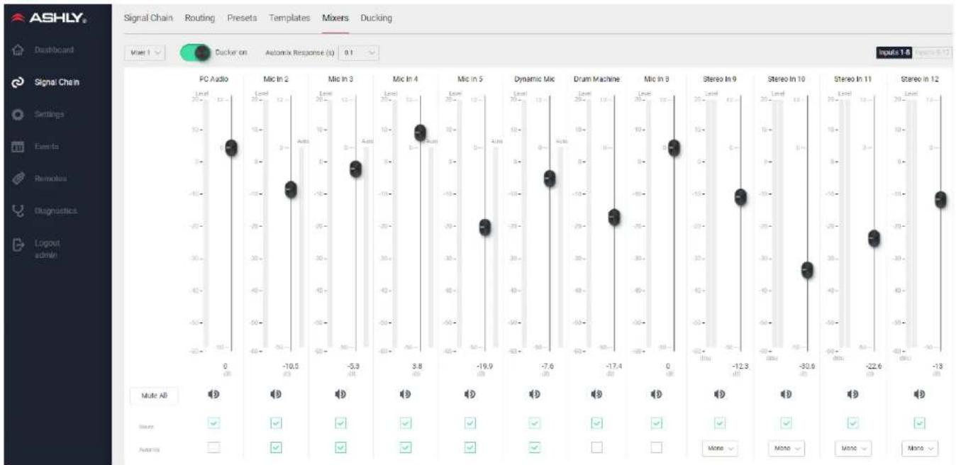
6.2h Signal Chain > Mixers 1-4
bar
| Audio Type | Level | Ducker on | Automix Response (x) | Mixers | Ducking | |---|---|---|---|---|---| | PC Audio | -10.5 | 12 | 0 | 0 | 0 | | Mic In 2 | -10.5 | 12 | 0 | 0 | 0 | | Mic In 3 | -5.8 | -10 | 12 | 0 | -4 | | Mic In 4 | 3.8 | 12 | 0 | 0 | 0 | | Mic In 5 | -19.9 | -10 | 12 | 0 | -3 | | Dynamic Mic | -7.6 | -10 | 0 | 0 | -4 | | Drum Machine | -17.4 | -10 | 12 | 0 | -25 | | Mic In 9 | 0 | 0 | 12 | 0 | 0 | | Stereo In 9 | -12.3 | -10 | 0 | 0 | -15 | | Stereo In 10 | -32.6 | -10 | 12 | 0 | -30 | | Stereo In 11 | -22.6 | -10 | 0 | 0 | -25 | | Stereo In 12 | -13 | -10 | 12 | 0 | -35 |Four independent mixers can be assigned to the two amplifier outputs or two aux outputs. Each mixer offers independent input channel level control, routing, mixer mute, ducking enable, automix assignment, and automix response time. Stereo input channels 9-12 can be set for left input only, right input only, or summed mono.
Automixer
The automixer is used to automate the mixing of multiple speech microphones to follow the dynamic nature of the speech dialog and attenuate idle microphones. The automixer may also be used in conjunction with the autoleveler, compressor, or gate on the input signal paths. This gives the user more advanced control of varied input signal levels produced by different talkers.
Ashly Auto Mixer Technology
The automixer function is a "gain-sharing" type which automatically makes smooth gain transitions on all automixer input channels to achieve a constant total system gain. This gain-sharing method of automixing has been found to be superior to gating automixers due to the following characteristics:
mXa-1502 • Operating Manual Ashly AquaControl™ Software
- The automatic gain action has a smooth transparent sound as though a person were mixing the inputs to follow the audio program rather than rapid gating on-and-off of channels.
- Properly designed gain-sharing automixers correctly adjust for mixing of coherent versus non-coherent signals for a more consistent final mix level without feedback as channel gains are automatically changing.
- A gain-sharing automixer is easier to setup and adjust without the need for threshold, attack, release, depth, and number-of-open-mics (NOM) controls.
Mixer input channels can be individually selected as auto-mixed or manual mixed, all summed together to the same mixer output. Channels which are selected as auto will participate in the automix in that they will contribute to the automatic adjustment of other automix channel gains. Likewise, their channel gain will be affected by the signal level present on other automix channels. Manual mixer channels (not selected as auto) will mix independently of the automixer channels into the output, only controlled by their fader setting. The fader on auto channels still controls the input level before automatic mixing takes place so that more of the system gain can be applied to one channel versus another.
Automixer Setup
Setting-up the Ashly gain-sharing automixer is quite simple compared to other gating-type automixers. The following procedure is recommended for most multi-microphone speech applications.
- Start with all mixer faders off and the automixer response time set to 0.1 seconds.
- Configure the mixer input channel routing as desired and select
on the channels to be automixed. - Start with one of the main speech channels, or one which is centrally located. Slowly increase the fader for this one channel just until feedback starts, then lower the fader approximately 3 dB to stay comfortably below feedback. This sets the total mixer system gain.
- Now increase the level of the other automix-enabled input channels to approximately the same position as the first channel. The system will not feedback because the automixer will slowly attenuate the active channels as more channels are turned-on to maintain a constant total system gain.
- During the program, individual channel faders may be raised or lowered to adjust for the weakness or strength of the respective talkers while the automixer is active.
mXa-1502 • Operating Manual Ashly AquaControl™ Software
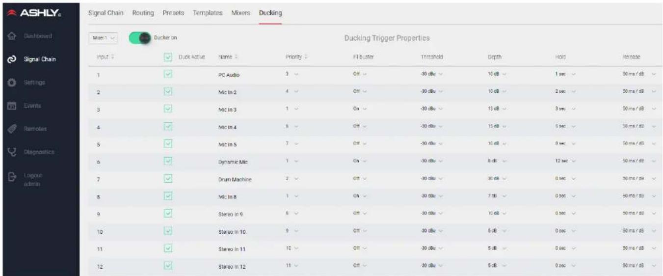
6.2i Signal Chain > Ducking
text_image
ASHLY Signal Chain Routing Presets Templates Mixers Ducking Mixer 1 Ducker on Ducking Trigger Properties Input: ✓ Duck Active Name: Priority: Filterer Threshold Depth Hold Release 1 ✓ PC Audio 3 ✓ Off -30 dBu ✓ 15 dB ✓ 1 sec ✓ 50 ms /dB ✓ 2 ✓ Mic In 2 4 ✓ Off -30 dBu ✓ 10 dB ✓ 2 sec ✓ 50 ms /dB ✓ 3 ✓ Mic In 3 1 ✓ On -30 dBu ✓ 13 dB ✓ 3 sec ✓ 50 ms /dB ✓ 4 ✓ Mic In 4 5 ✓ Off -30 dBu ✓ 15 dB ✓ 5 sec ✓ 50 ms /dB ✓ 5 ✓ Mic In 5 7 ✓ Off -30 dBu ✓ 16 dB ✓ 8 sec ✓ 50 ms /dB ✓ 6 ✓ Dynamic Mic 1 ✓ On -30 dBu ✓ 8 dB ✓ 12 sec ✓ 50 ms /dB ✓ 7 ✓ Drum Machine 2 ✓ Off -30 dBu ✓ 30 dB ✓ 0 sec ✓ 50 ms /dB ✓ 8 ✓ Mic In 8 1 ✓ On -30 dBu ✓ 7 dB ✓ 0 sec ✓ 50 ms /dB ✓ 9 ✓ Stereo In 9 8 ✓ Off -30 dBu ✓ 15 dB ✓ 0 sec ✓ 50 ms /dB ✓ 10 ✓ Stereo In 10 9 ✓ Off -30 dBu ✓ 5 dB ✓ 0 sec ✓ 50 ms /dB ✓ 11 ✓ Stereo In 11 10 ✓ Off -30 dBu ✓ 5 dB ✓ 0 sec ✓ 50 ms /dB ✓ 12 ✓ Stereo In 12 11 ✓ Off -30 dBu ✓ 5 dB ✓ 0 sec ✓ 50 ms /dB ✓- Ducker On/Off: Each of the four mixers offer independent ducking control, with a master Ducker On/Off button for each mixer.
- Duck Active: Each of the 12 input channels can be selected as ducking active or inactive independently in each of the four mixers.
- Stereo Input Ducking: For channels 9-12, the highest-level input (L/R) is used for the ducking detector.
-
Priority: Input channels activated for ducking can be assigned a priority from 1 to 12, with 1 being highest priority. Multiple inputs can share the same priority level.
-
Filibuster: An active ducking input with filibuster ON will maintain exclusive control over all other active ducking inputs sharing the same priority number and which have filibuster ON. Control is given up when the input signal to the active filibuster channel falls below its trigger threshold.
-
Threshold: The ducking trigger threshold determines the input signal level that will initiate ducking control of that channel over other active ducking channels that have been assigned a lower priority.
-
Depth: The ducking depth is the reduction in signal level applied to lower priority ducked channels when the current channel becomes the active input.
- Hold: The hold function determines how long a lower priority channel remains ducked to the full depth after the active channel's level drops below its threshold setting. Ducked channels begin to release after the hold time.
- Release: The time it takes for all channels ducked by the current active channel to return to normal level after the active channel level drops below its threshold setting and the hold time is reached.
mXa-1502 • Operating Manual Ashly AquaControl™ Software
6.2j Signal Chain > Routing
| ASHLY | ||||||||||||
| Input | 1 PC Audio | 2 Mic In 2 | 3 Mic In 3 | 4 Mic In 4 | 5 Mic In 5 | 6 Dynamic Mic | 7 Drum Machine | 8 Mic In 8 | 9 Stereo In 9 | 10 Stereo In 10 | 11 Stereo In 11 | 12 Stereo In 12 |
| Mixer 1 | ||||||||||||
| Mixer 2 | ||||||||||||
| Mixer 3 | ||||||||||||
| Mixer 4 | ||||||||||||
| Output | Name | Source | ||||||||||
| 1 | Speaker Out 1 | Mixer 1 | ||||||||||
| 2 | Speaker Out 2 | Mixer 2 | ||||||||||
| 3 | Aux Out 1 | Mixer 3 | ||||||||||
| 4 | Aux Out 2 | Mixer 4 | ||||||||||
The signal chain routing page provides fast setup and review of all 12 input channel routings to all four mixers.
It also provides for mixer 1-4 assignment to the two power amplifier channels, as well as the Aux 1-2 line level outputs.

mXa-1502 • Operating Manual Ashly AquaControl™ Software
6.3 Settings
The settings pages are where general settings, panel settings, network settings, and security settings get configured.
6.3a Settings > General Settings (not shown)
This shows the current device, its firmware/hardware revision, allows naming the device and group, and configures the Real Time Clock. This is also where you Export/Import all settings to back up or clone your device, and where you perform firmware update if one is available on the Ashly website.
Please note: The time required to export and import all settings will increase depending on the quantity and file size of custom images loaded into the "background image" feature of the Virtual WR-5 remote. See sec 6.5c
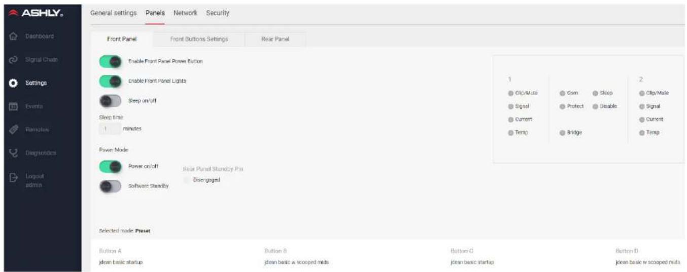
text_image
ASHLY. General settings Panels Network Security Front Panel Front Buttons Settings Rear Panel Enable Front Panel Power Button Enable Front Panel Lights Sleep on/off Sleep time 1 minutes Power Mode Power on/off Rear Panel Standby Pin Software Standby Disengaged Selected mode: Preset Button A Button B Button C Button D jdean basic startup jdean basic w scooped mids jdean basic startup jdean basic w scooped mids6.3b Settings > Panels > Front Panel (shown above)
- Enable Front Panel Power Button: On/Off
- Enable Front Panel Lights: On/Off
-
Enable Sleep Mode: On/Off, plus sleep time setting. Note: Sleep time of "0" = 15 seconds.
-
Enable Power: On/Off
- Enable Software Standby: On/Off
-
Rear Panel Standby Pin: engaged/disengaged
-
Front Panel LEDs: displays current status
- Front Panel Select Buttons A-D: shows current assignment status

mXa-1502 • Operating Manual Ashly AquaControl™ Software
6.3c Settings > Panels > Front Button Settings
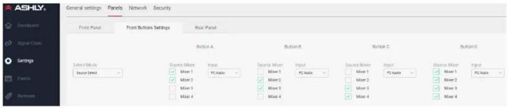
text_image
ASHLY Development Signal Close Settings Events Remount General settings Panels Network Security Front Panel Front Buttons Settings Rear Panel Button A Button B Button C Button D Select Mode Source Mixer Input Source Mixer Input Source Mixer Input Source Mixer Input Source Mixer Mixer 1 PC Audio Mixer 1 PC Audio Mixer 1 PC Audio Mixer 1 PC Audio Mixer 2 Mixer 2 Mixer 2 Mixer 2 Mixer 2 Mixer 2 Mixer 2 Mixer 2 Mixer 2 Mixer 2 Mixer 2 Mixer 2 Mixer 2 Mixer 2 Mixer 2 Mixer 2 Mixer 2 Mixer 2 Mixer 2 Mixer 2 Mixer 2 Mixer 2 Mixer 2 Mixer 2 Mixer 2 Mixer 2 Mixer 2 Mixer 2 Mixer 2 Mixer 2 Mixer 2 Mixer 2 Mixer 2 Mixer 2 Mixer Source Data Source Data Source Data Source Data Source Data Source Data Source Data Source Data Source Data Source Data Source Data Source Data Source Data Source Data Source Data Source Data Source Data Source Data Source Data Source Data Source Data Source Data Source Data Source Data Source Data Source Data Source Data Source Data Source Data Source Data Source Data Source Data Source Data Source Data Source Data Source Data Source Data Source Data Source Data Source Data Source Data Source Data Source Data Source Data Source Data Source Data Source Data Source Data Source Data Source Data Source Data Sources Source Data Source Data Source Data Source Data Source Data Source Data Source Data Source Data Source Data Source Data Source Data Source Data Source Data Source Data Source Data Source Data Source Data Source Data Source Data Source Data Source Data Source Data Source Data Source Data Source Data Source Data Source Data Source Data Source Data Source Data Source Data Source Data Source Data Source Data Source Data Source Data Source Data Source Data Source Data Source Data Source Data Source Data Source Data Source Data Source Data Source Data Source Data Source Data Source Data Sources Mixer 1 PC Audio Mixer 1 PC Audio Mixer 1 PC Audio Mixer 1 PC Audio Mixer 1 PC Audio Mixer 1 PC Audio Mixer 1 PC Audio Mixer 1 PC Audio Mixer 1 PC Audio Mixer 1 PC Audio Mixer 1 PC Audio Mixer 1 PC Audio Mixer 1 PC Audio Mixer 1 PC Audio Mixer 1 PC Audio Mixer 1 PC Audio Mixer 1 PC Audio Mixer 1PCAudio6.3d Settings > Panels > Rear Panel
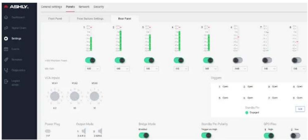
text_image
ASHLY General settings Panels Network Security Front Panel Front Buttons Settings Rear Panel +V-Ray Panama Power mix Gain 0.65 448 0.6 0.6 0.6 348 148 0.6 vCA Input VCA1 VCA2 VCA3 6.2 10 10 Dripers 1 Open 2 Open 3 Open 4 Open 5 Open 6 Open 7 Open 8 Open Standby Pin Engaged Power Plug Output Mode Bridge Mode Standby Pin Polarity GPS Pins 117 2/4/0 2/4/0 Enabled High Low- Select Mode: Front panel buttons A, B, C, D are configured as a group to: None (default), Preset Recall, Sub-Preset Recall, or Source Select (shown).
- Presets/Sub-Presets are chosen from drop down list.
- Source Select: Each button will apply one exclusive input to mixer(s) 1-4.
- Mic Pre 1-8: Set +48V phantom power, set preamp gain, view input signal level LED display
• VCA Inputs (1-3): Shows current VCA control position
- Trigger 1-8: Shows current pin status, press Edit button to review all triggered events
• Power Plug: Displays current AC line voltage
• Output Mode: Shows currents settings of rear panel DIP switches for Low-Z, 25V, 70V, or 100V output
• Bridge Mode: Enabled, disabled (default)
- Standby Pin Polarity: Set to trigger standby on high, or trigger on low (default)
• GPO 1-2 pins: Set/display current GPO pin status

mXa-1502 • Operating Manual Ashly AquaControl™ Software
6.3e Settings > Network
Network configuration can be set and saved as automatic (DHCP) or manual (Static IP).
If deploying a virtual software remote to a phone or tablet, use the IP address show on this page in the remote device's internet browser.
The device MAC address is also displayed here. An "Identify Device" button pings the device to visually identify itself by turning on its green COM LED for 10 seconds. The Reset button sets all network parameters back to defaults.
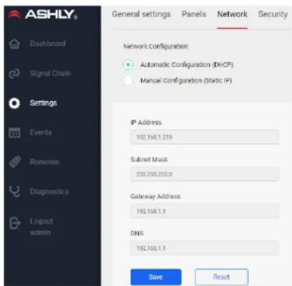
text_image
ASHLY® Dashboard Signal Chain Settings Events Remotes Diagnostics Logout admin General settings Panels Network Security Network Configuration: Automatic Configuration (DECP) Manual Configuration (Static IP) IP Address 192.108.1.219 Submit Mask 205.205.205.0 Gateway Address 192.108.1.1 DNS 192.108.1.1 Save Reset6.3f Settings > Security (not shown)
There are four levels of security roles: Admin, Guest Admin, Operator, and View Only.
User accounts are created by the Admin using the New Profile button, then given a unique username, security role, and password.
- Admin Role: Always has full access.
- Guest Admin Role: Can be granted full access, or any combination of the following permissions:
- Edit Accounts
- Remote Logout
- Edit Device Misc.
- Event Log Clear
- Event Scheduler edit
- Front Panel Controls edit
- Rear Panel Controls edit
- Network Settings edit
- Paging Ducking edit
- Preset edit
- Preset Recall
- System Time edit
- Trigger Settings edit
- Edit Signal Chain
- Import/Export Setting
- Operator Role: Has a reduced list of available permissions. Each permission must be authorized by an Admin, or by a Guest Admin who has the "Edit Accounts" permission granted.
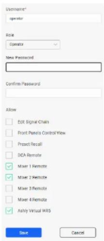
text_image
Username* operator Role Operator New Password Confirm Password Allow Edit Signal Chain Front Pixels Control View Project Recall DCA Remote Mixer 1 Remote Mixer 2 Remote Mixer 3 Remote Mixer 4 Remote Ashly Virtual WRS Save CancelTypical use of the Operator role might be for deploying a Remote Mixer, Remote DCA, remote Virtual WR5, or AquaTouch7 to a secure but limited access user, or for granting the operator signal chain or preset recall access.
Allowed Operator permissions can be individually selected, and include the following options:
- Edit Signal Chain
- Front Panel Controls View
- Preset Recall
- DCA Remote
- Mixer 1-4 Remote
- Custom Virtual WR5 Remote
View Only Role: Users can view, but are denied access to all controls and settings.

mXa-1502 • Operating Manual Ashly AquaControl™ Software
6.4 Events
Events can be scheduled using the internal real-time-clock (RTC), or triggered by a logic input connected to rear panel Trigger Input 1-8. Multiple actions can be included in a single event, and a delay time can be added before each action as the event sequence is executed.
Use the New Event command to create events. Events can also be cloned, edited, and deleted.
Events > Event List
All programmed events, scheduled or triggered, are listed by event name, event type, and actions. Click on any event in the list to test, clone, edit, or delete that event. New events can be added from this page.
Events > Scheduled Events
Scheduled events are programmed and saved within the unit, then executed based on the real time clock. Events can be scheduled for one time, daily, weekly, or yearly.
Several actions can be grouped together in sequence, but still be part of a single scheduled event. A delay time up to 99 seconds can be inserted before each individual action within the sequence.
Scheduled event action types include the following:
- Cancel Today's Events: Over-rides all other scheduled events for the day, ending at midnight.
- Channel Mute: Mutes selected input or output channels, but does not affect mixer mute.
- Channel Un-mute: Un-mutes selected channels, but does not affect mixer mute.
• GPO High: Sets GPO pin 1 or pin 2 to logic high
• GPO Low: Sets GPO pin 1 or pin 2 to logic low
- Gain Decrement / Increment: Reduces or increases the gain of selected channels by a fixed amount, up to +/- 6dB. Note: A Gain block must first be placed on the selected channel(s).
- Mixer Mute: This mutes the selected mixer channel(s), but does not affect input or output channel mute.
- Mixer Un-mute: Un-mutes selected mixer channel(s), but does not affect input or output channel mute.
• Power Off: Turns the amplifier off
• Power On: Turns the amplifier on
- Preset Recall: Recalls one preset from device memory.
- Resume Today's Schedule: Undoes the "Cancel Today's Events" event.
- Source Select: Selects input channels for any or all mixers.
- Subpreset Recall: Recalls one sub-preset from device memory.
Events > Triggered Events
Triggered events are assigned to one of eight rear panel contact closure trigger input pins. The event is triggered when the input pin is connected to the ground pin.
Triggered event action types include the following:
- A/B Source Select: This toggles between two sets of selected input channel sources for any or all designated mixers.
• Action Sequence: Select multiple actions from one triggered event. Delay times up to 99 seconds can be inserted before each action. - Channel Mute: Selects Signal Chain inputs or outputs to be toggled as muted or unmuted, this does not affect mixer mute status.
- General Purpose Output (GPO) Toggle: For turning on/off an external device. Sets GPO pin(s) low when closed, or high when open.
- Mixer Mute: Selected Mixer channels can be toggled as muted or unmuted. This does not affect signal chain input or output mute status.
- Paging: Toggles a normally off input channel to serve as a paging input, turning it on and applying it to all assigned mixers without affecting other inputs, unless Ducking priority has been applied.
- Pause/Resume Schedules: Interrupts all scheduled events when closed, resumes all scheduled events when open.
- Preset Toggle: Toggles between two selected presets.
mXa-1502 • Operating Manual Ashly AquaControl™ Software
6.5 Remotes (software)
Virtual Remotes can be created, configured and deployed to users in the field over an existing IP network, allowing secure but limited access to selected mXa-1502 features. Software remotes would typically be used on a phone, tablet, or Ashly's AquaTouch7 via an Operator role that has been granted limited permissions by the Admin in the Settings>Security page. Available remote interfaces include Mixer 1-4, DVCA, and Virtual WR5.
After an Operator role is created and its permissions selected, the mXa-1502 IP address as shown on the Settings>Network page is given to the Operator. The Operator connects their remote device using this IP address in their browser, then logs in with the User ID and password provided by the Admin. Once they log in, they will see only the features permitted by the Admin for their account profile. Note: An Operator who is only granted Remote permissions cannot log out of their remote once logged in.
For future Operator access* to a deployed remote without having to enter IP address or credentials, a bookmark or application icon should be made.
* In order to retain the network link for the virtual remote for future use, the remote operator should additionally check [Remember Me] when first logging in.
6.5a Mixers 1-4
Any or all of the four mixers are available to be deployed an authorized Operator. The only mixer functions available to the Operator are individual input channel level and mute. As long as an input channel is routed to a mixer, it will appear on that remote mixer's page.
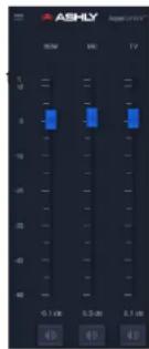
text_image
ASHLY RSM MC TV 0.1 am 0.5 am 2.1 am6.5b DVCA
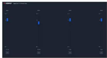
text_image
ASB-1 A## 12.000000000000000 MIL 2001 2002 2003 5% 6% 7% 8% 9% 10% 11% 12% 13% 14% 15% 16% 17% 18% 19% 20% 21% 22% 23% 24% 25% 26% 27% 28% 29% 30% 31% 32% 33% 34% 35% 36% 37% 38% 39% 40% 41% 42% 43% 44% 45% 46% 47% 48% 49% 50%DCA groups are used to globally adjust the relative levels of all channels assigned to that group. In the DSP signal chain, a DCA block must first be placed on every channel you wish to assign to a DCA group, then enabled and adjusted for each DCA group as desired. A remote Operator role is then created granting permission to use a DCA Remote on a tablet or mobile device.
mXa-1502 • Operating Manual Ashly AquaControl™ Software
6.5c Virtual WR5
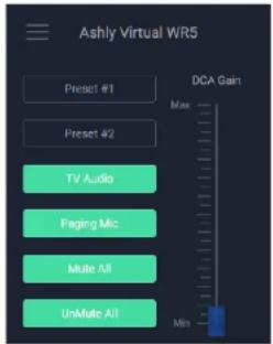
text_image
Ashly Virtual WR5 Preset #1 Preset #2 TV Audio Paging Mic Mate All UnMate All DCA Gain Max MinAshly's WR-5 wall remote is a popular solution for audio installation remote control applications using other Ashly products.
A Virtual WR5 was created in AquaControl software. It has a similar appearance to the original WR-5 and is easily programmable in the software.
- A virtual WR5 can be securely deployed to a phone. tablet, or Ashly's AquaTouch7 wall remote, for customized remote control access to any Ashly AquaControl enabled device.
- The Virtual WR5 has six programmable buttons and one programmable fader.
- Button Action Types include: None, Preset Recall, Sub-Preset Recall, Source Select, Channel Mute, and Fader Channel Select.
- Fader Action Types include: None, Mixer Input Gain, DCA Gain, and Channel Gain.
- Background and foreground images can be added by the user to customize the virtual WR5 appearance, particularly useful when used with an AquaTouch7 wall remote.
- Note: Any custom images added for virtual WR5 background become part of the software settings stored within the unit. The maximum number of background images that can be stored in memory is 5 @ 3.5MB per image file. Storing image files will lengthen the time it takes to Export/Import all settings.
To create a new virtual WR5 in AquaControl, go to the Remotes page and click [Create Virtual WR5 Remote], then follow these steps:
1) Name the Remote.
2) Click on any Button (or Fader) and assign an Action Type to it.
3) Enter Button (or Fader) Label text
4) Enter your specific configuration for the selected Action Type.
5) Select the Theme as Light or Dark.
6) Add any background or foreground images if desired
6) Click the Save button.
To view and test the new WR5 before deploying it, return to the main Remotes page, select the new WR5, then click [View Remote].
After a virtual WR5 is created and saved, it will automatically appear in the list of allowed functions for an Operator role. See the [Settings>Security] page for further details.
6.5d AquaTouch7
The AquaTouch7 is a 7" wall-mount touchscreen tablet exclusively designed for Ashly AquaControl devices. It mounts to a standard electrical box, and uses a wired Ethernet connection for secure remote control. Wi-Fi connection is not supported.

text_image
ASHLY AquaTouch 7The system admin can create and securely deploy one of the previously described custom remote control surfaces for use by a remote operator.
Note: The AquaTouch7 can also function as a complete GUI for the host device if the user is logged in as Admin, however the reduced feature size on its 7" screen makes it difficult to access certain graphical software features. A minimum 10" screen is recommended for configuring AquaControl.
For more details on AquaTouch7, please visit the Ashly website.
6.6 Diagnostics
Diagnostics monitor and record a log of user selected activity, useful for debugging system issues or viewing user activity. The log can be exported as a spreadsheet *.csv file.
The log feature can monitor and record the following activity categories and display results for a specified date range.
- Status
- Operation
- Events
- Presets
- Security
- Network
mXa-1502 · Operating Manual
7 Remote Control (wired)
7.1 VCA Level Control Inputs
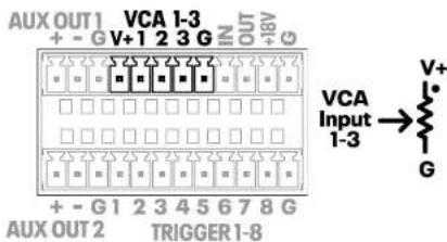
text_image
AUX OUT1 VCA 1-3 + - G V+1 2 3 G IN OUT +8V G VCA Input 1-3 → V+ G AUX OUT2 TRIGGER 1-8Remote DC level control is available on these three VCA (voltage controlled amplifier) inputs. A VCA Gain block must first be placed in an input or output signal chain, then assigned to a VCA input. Multiple VCA gain blocks can be assigned to the same VCA input pin.
Ashly WR-1, WR-1.1, or WR-1.5 remotes can be used for DC level control, or a custom control can be made using a 10k Ohm potentiometer and wired as shown. The dot indicates the potentiometer clockwise position, full volume.
7.2 Trigger Logic Inputs
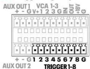
text_image
AUX OUT 1 VCA 1-3 + - GV+1 2 3 GIN OUT + - G 1 2 3 4 5 6 7 8 G AUX OUT 2 TRIGGER 1-8Eight programmable trigger inputs are available for use with contact closure switches.
Triggered events are programmed in the software Events page, [Events>Triggered Events>New event].
Triggered events include: A/B Source Select, Action Sequence, Channel Mute, GPO Logic Toggle, Mixer Mute, Paging, Pause/Resume Schedules, and Preset Toggle. Connecting a trigger input to the [G] pin (ground) triggers the event.
Current trigger status can be viewed in the [Settings>Panels>Rear Panel] page.
7.3 GPO Logic Outputs
Two GPO (general purpose output) pins are available for driving external device logic inputs to effect a lighting change, motorized curtain, projector screen, etc. GPO logic status can be recalled as part of a preset or sub-preset, or changed using a scheduled or triggered event.
Current logic high/low status can be viewed or set in the [Settings>Panels>Rear Panel] page.
7.4 Amp Fault Logic Outputs
An amplifier fault is any condition that places the amplifier into a protect state. Faults can include output overcurrent, thermal, mains overvoltage, internal mains fuse, and output DC. If an amplifier channel goes into protect mode, the amp fault output pin for that channel goes logic low.
7.5 Remote Standby
Standby mode puts the amplifier into a muted, reduced power state. Standby mode can be
activated via software or with the standby pin Euroblock connection.
Standby pin polarity can be set in software to Trigger on Low or Trigger on High [Settings>Panels>Rear Panel].
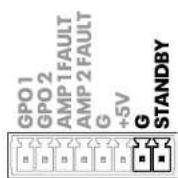
The Standby contact closure pin has priority over software standby.
7.6 Ashly Remotes
WR-1 and WR-1.1
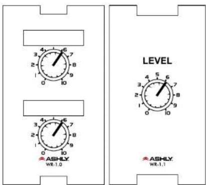
text_image
ASHLY WR-1.0 LEVEL ASHLY WR-1.1The WR-1 and WR-1.1 are remote level controllers used for DC level control inputs. The WR-1 (dual potentiometer) and WR-1.1 (single potentiometer) mount to a standard North America electrical wall box. The remote is wired
mXa-1502 • Operating Manual
to the mXa-1502 Euroblock VCA pins V+, 1, 2, or 3, and ground, then associated in software with a VCA Gain block placed anywhere in the signal chain.
If using a potentiometer other than the WR-1, use 10k Ohm and wire the mXa V+ pin to the potentiometer's clockwise terminal, GND to the counter-clockwise terminal, and VCA pin 1-3 to the wiper. Do not connect the WR-1 ground connection to any external grounds.
WR-1.5
The WR-1.5 offers a single rotary potentiometer for DC level control, plus with a four-position rotary switch for triggering events using mXa-1502 trigger inputs.
WR-2 Event
Trigger Switches
The WR-2 lockout push-button remote can trigger up to four different events that have been programmed into the mXa-1502. Each pushbutton switch gets connected to a trigger input pin. When a switch is pressed, it triggers the event programmed for that trigger input.
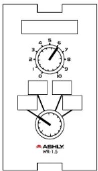
text_image
ASHLY WR-1.5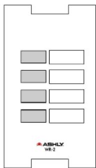
text_image
ASHLY WR-28 Amplifier Protection
Over Current Protection - When the output current exceeds the amplifier's safe operating limits. This occurs in the amplifier output stage.
Thermal Protection - The amplifier senses output device temperature and adjusts fan speed to keep the operating temperature within acceptable limits. If device temperatures exceed that limit, the input level to that channel is first reduced, and as a last resort the power supply will be switched off.
Mains Protection – Protection within the power supply includes:
• In-rush Current Limitation during power up
- Mains Over Voltage Detection
• Internal Mains Fuse Protection
To protect the Mains fuse against AC overcurrent due to excessive audio output current, there is a protection scheme indicated on the front panel which reduces audio output level until the overcurrent condition is no longer present.
DC Output Protection – If the amplifier senses DC on an output it shuts down the power supply.
9 Troubleshooting
No AC Power
- Is the detachable AC power cord properly installed? Is it plugged into a known live outlet?
- Has the power switch been disabled?
No Amplifier Output
- Is the amplifier on, indicated by the illuminated front panel power button?
• Is the amplifier in protect or standby mode? - Is the input signal properly wired to either a mic/line input or RCA line input?
- Are remote control or software level controls turned down?
- Is the signal muted from DSP, remote control, mixer, or a triggered/scheduled event?
- Are dynamics or gain tool settings in the signal chain allowing signal to pass properly?
- Is signal routed to the correct output channel in the mixer matrix?
- Are level controls set properly in the mixer?
- Has a scheduled or triggered event changed settings?
Still Not Working?
- Contact Ashly technical support at 1-800-705-2102, or email service@ashly.com
mXa-1502 · Operating Manual
Specifications
| Maximum Output PowerCEA-2006/490A, 20ms 1kHz 1%THD+N, 480ms 1kHz -20dB, 120VAC all channels driven at rated load ow Z output, per channel | |
| Low Z output, per channel | |
| 8 Ohm 150W | |
| 4 Ohm 150W | |
| 2 Ohm 150W | |
| Low Z output, per bridged channel pair | |
| 8 Ohm 300W | |
| 4 Ohm 300W | |
| Hi-Z output, per channel | |
| 25V 150W | |
| 70V 150W | |
| 100V 150W | |
| Hi-Z output, per bridged channel pair | |
| 25V 300W | |
| 70V 300W* | |
| 100V 300W* | |
| *May require Class 3 speaker wiring, all others use Class 2 wiring. | |
| Total AC Mains Power DrawTypical input, all channels driven, 120VAC | |
| Sleep <4W | |
| Standby 24W | |
| Idle (no signal) 41W | |
| 1/8 power, 4 Ohms 90W | |
| AC Mains Current DrawTypical input, all channels driven 120VAC (divide in half for 240V) | |
| Sleep mode 0.14A | |
| Standby mode 0.29A | |
| Idle (no signal) 0.40A | |
| 1/8 power, 4 Ohms 0.81A | |
| Thermal Dissipationin BTU/hour with typical input, all channels driven, 120VAC | |
| Sleep mode 13BTU/h | |
| Standby | 82BTU/h |
| Idle (no signal) 140BTU/h | |
| 1/8 power, 4 Ohms 307BTU/h | |
| Damping Factor,8 ohm load, <1kHz | >250 |
| Distortion,SMPTE, typical | <0.5% |
| Distortion,THD+N, typical | <0.5% |
| Channel Separation,dB from full output, 1kHz | -75 dB |
| Signal to Noise,20Hz-20KHz, unweighted | >99 dB |
| Frequency Response | 20Hz-20kHz, ±0.2dB |
General Specifications
| Mic/Line Input | Euroblock 3.5mm |
| Input Impedance | Active balanced, 18kΩ |
| Maximum Input Level | +21dBu |
| Input Gain Range | 0dB to +66dB |
| Phantom Power | +48V, software switchable per channel |
| Stereo Line Input | Dual RCA, unbalanced |
| Input Impedance | 10.0KΩ |
| Maximum Input Level | +3.8dBy (+6dBu) |
| AUX Output | Aux 1, Aux 2, Euroblock 3.5mm, balanced |
| AUX Out Maximum Level | +21 dBu |
| Speaker Output | Euroblock 7.62mm |
| VCA 1-3 input | Euroblock 3.5mm +1.8V, VCA pins 1-3, G |
| Data Connection (reserved for future use) | Euroblock 3.5mm Data In/Out, +18V, Gnd |
| Trigger 1-8 contact closure input | Euroblock 3.5mm assignable function |
| GPO 1 & 2 general purpose outputs | Euroblock 3.5mm assignable function |
| Amplifier Fault 1 & 2 logic outputs | High (+3V) when amp channel is on and ok, low (0V) when amp channel is off or in a protect/fault state |
| Remote StandbyContact Closure | Euroblock 3.5mmwith polarity switch |
| Ethernet | RJ45, 100MB/1GB |
| Output Mode selectper amp channel | 4 pos. DIP switchLo-Z - 2Ω, 4Ω, 8ΩHi-Z - 25V, 70V, 100V |
Front Panel LED Features
| Clip/Mute LED | Red, ON at max output power, mute, level fully off |
| Signal LED | Green, ON at 18dB below full output |
| Current LED | Green, ON when >0.5A current delivered to speaker load |
| Temp LED | Yellow, ON when countermeasures applied for excess heat |
| Power LED | White, ON, OFF, Flashing for Standby |
| Com LED | Green, ON during Ethernet activity |
| Protect LED | Red, ON for amp fault causing shut-down |
| Sleep LED | Blue, ON for sleep mode |
| Disable LED | Yellow, ON when power switch disabled |
| Bridge LED | Green, ON when amp is in bridge mode |
| Front Panel Select Buttons | A, B, C, D, programmable for source select or preset/sub-preset recall |
| Factory reset | see section 3.3 |
| Processors | |
| Input A/D: | 32 bit |
| Output D/A: | 24 bit |
| DSP Processors: | 32-bit floating point |
| Sample Rate: | 48kHz |
| Propagation Delay | 1.02 ms |
mXa-1502 • Operating Manual
Miscellaneous
| Compatible Ashly Remote Control Devices | WR-1, WR-1.1, WR-1.5, WR-2, AquaTouch7 |
| Amplifier Protection | inrush current, output DC, temperature monitoring, output over-current protection, internal mains fuse |
| Cooling Fan | Variable, air flows in the front-right vents, out front-left vents |
| Software Control | Ashly AquaControlTM Software, served from amplifier |
| Power Requirements 100-240VAC, 50/60Hz | |
| Power Cable Connector | 15A Edison, detachable |
| Unit Weight 11.6 lbs (5.26 kg) | |
| Unit Dimensions | 19"W x 1.75"H x 14.6"D (483 x 44.5 x 371mm) |
| Shipping Weight 14.5 lbs (6.58 kg)) | |
| Shipping Dimensions | 25.2"W x 2.5"H x 19.5"D 641mm x 64mm x 495mm |
| Environmental | 40°-120°F (4°-49°C) noncondensing |
| Safety/Compliance CE, FCC Class B, RoHS | |
Ashly AquaControl™ Software Specifications
| Dashboard | |
| General | |
| Display | current device, number of inputs, number of outputs, firmware revision |
| Controls Launch Quick Setup | |
| Signal Chain > Main Page | |
| General | |
| Screen Display | Editor or Diagram Mode |
| Hide Unused Channels | On/Off |
| Presets | Save Preset / SubPreset |
| Mixer 1-4 | Edit, Show Chains, Add to Subpreset |
| Mic Inputs 1-8 | |
| +48V Phantom Power | per channel, On/Off |
| Mic 1-8 Preamp Gain | 0dB to +66dB, 6dB steps |
| Mute per channel, On/Off | |
| Utility Functions(per channel) | copy chain, add mute to sub preset, save template, load template, clear chain |
| Stereo Line Inputs 9-12 | |
| Mute per channel, On/Off | |
| Utility Functions same as mic inputs | |
| Output Channels 1-4 | |
| Mute per channel, On/Off | |
| Utility Functions(per channel) | copy chain, add mute to sub preset, add mixer connection to subpreset, save template, load template, clear chain |
| Routing Matrix | |
| Available Inputs | 12 |
| Available Mixers 4 | |
| Available Outputs 2 speaker, 2 aux | |
| Output Source Select | mixer 1-4, none |
| Presets | |
| Preset Functions | preview, recall, rename, delete, export, import |
| Templates | |
| Template Functions | rename, delete, import, export |
| Mixer 1-4 | |
| Input Level Fader -50dB to +12dB, Off | |
| Input Level Meter -60dB to +20dBu | |
| Mute | mute per mixer channel, mute all |
| Route Enable | per input channel, enable/disable |
| Automix Assign | per input channel, enable/disable |
| Automix Response 0.01s to 1.2s | |
| Ducker per mixer, On/Off | |
| Ducking | |
| Ducker per mixer, On/Off | |
| Ducking Input Channels | 12 |
| Priority per channel, 1-12 | |
| Filibuster | per channel, On/Off |
| Trigger Threshold | -70dBu to +20dBu |
| Depth | per channel, 0-30dB, -inf |
| Hold | per channel, 0-60 sec. |
| Release | 2ms/dB to 1000ms/dB |
(continued on next page...)
mXa-1502 • Operating Manual
Signal Chain > Pluggable DSP Blocks
DSP functions can be linked using one of 16 link groups
Ambient Noise Compensation (outputs only)
On/Off, Compare
Compensation:
Max Gain -40dB to +20dB
Min Gain -40dB to +20dB
Gain Change Rate 0.2s/dB to 20s/dB
Input Level Meter -40dBu to +20dBu
ANC Gain Meter -40dB to 0dB
Ambient Noise:
Mixer Input Channel Mic 1-8, Stereo Line 9-12
Noise Threshold -40dBu to +20dBu
Prog/Amb Gain Ratio 0.3:1 to 3:1
Avg. Noise Meter -40dBu to +20dBu
Audio Meter
Range -60dBu to +20dBu
Autoleveler (On/Off, Compare)
Action gentle, normal, aggressive
Target Level -40dBu to +20dBu
Maximum Gain 0dB to +27dB
Metering Input, Gain
Advanced Autoleveler Controls:
Ratio 1.2:1 to 10:1
Gain Decrease Rate 5ms/dB to 1000ms/dB
Gain Increase Rate 5ms/dB to 1000ms/dB
Hold Time 0-6 sec
Threshold Below Target -30dB to 0dB
Brick Wall Limiter (link groups not available)
On/Off, Compare
Threshold -20dBu to +20dBu
Ratio infinite
Attack 0.2ms/dB to 50ms/dB
Release 5ms/dB to 1000ms/dB
Compressor (On/Off, Compare)
Detector Types | Peak, Average
Attenuation Bus none, 1-4 available
Threshold -20dBu to +20dBu
Ashly AquaControl™ Software Specifications (continued...)
| Ratio | 1.2:1 to infinite |
| Attack 0.2ms/dB to 50ms/dB | |
| Release | 5ms/dB to 1000ms/dB |
| Metering | input, output in dBFS total attenuation in dB |
Crossover (outputs only)
| Output Select | Speaker Out 1-2, Aux Out 1-2 |
| Filter Frequency | 20Hz-20kHz |
Filter Types: (available slopes in dB/octave)
| Bessel | 12, 18, 24, 30, 36, 42, 48 |
| Butterworth | 6, 12, 18, 24, 30, 36, 42, 48 |
| Butterworth/Linkwitz | Same as Butterworth 18 |
| Linkwitz 12, 24, 36, 48 | |
| Linkwitz Notch | 4th order, 8th order |
DCA Gain (On/Off, Compare)
| Level | -50dB to +12dB |
| Polarity | normal, inverted |
DCA Groups 1-4 (per group):
| Level | -50dB to +12dB |
| Mute On/Off | |
| Enable for channel | On/Off |
Delay (On/Off, Compare)
| Delay Time | 0-682 ms |
| Delay Length (at 22°C) | 0-770 ft, 0-235 m |
| Temperature | -30°F to +150°F |
| Compensation | (-34°C to +65°C) |
FIR Filter (outputs only)
Add FIR File, On/Off, Compare
| Sample Rate | 48kHz |
| Number of Taps | up to 512 |
| Loadable File Types | *.csv, *.fir, |
Gain (On/Off, Compare)
| Range | -50dB to +12dB, polarity invert |
Gate (On/Off, Compare)
Threshold -80dBu to +20dBu
Attack 0.2ms/dB to 50 ms/dB
| Range 0dB to 100dB, off | |
| Release | 5ms/dB to 1000ms/dB |
| Metering Key Signal | |
| Advanced Gate Controls: | |
| Key Frequency | 20Hz-20kHz |
| Key Bandwidth | 0.016 to 15 oct |
Graphic Equalizer (On/Off, Compare)
| Number of Filters | 31 |
| Filter Type | constant Q, proportional Q |
| Bandwidth | 0.499 to 0.25 octave |
High Pass Filter (On/Off, Compare)
| Filter Types: (available slopes in dB/octave) | |
| Bessel | 12, 18, 24, 30, 36, 42, 48 |
| Butterworth | 6, 12, 18, 24, 30, 36, 42, 48 |
| Butterworth/Linkwitz | 18 |
| Linkwitz-Riley | 12, 24, 36, 48 |
| Linkwitz Notch | 4th order, 8th order |
Low Pass Filter (On/Off, Compare)
| Filter Types: (available slopes in dB/octave) | |
| Bessel | 12, 18, 24, 30, 36, 42, 48 |
| Butterworth | 6, 12, 18, 24, 30, 36, 42, 48 |
| Butterworth/Linkwitz | 18 |
| Linkwitz-Riley | 12, 24, 36, 48 |
| Linkwitz Notch | 4th order, 8th order |
Parametric Equalizer (On/Off, Compare)
| Number of filter bands | 10 |
| Filter Types: | |
Parametric
| Frequency | 20-20kHz |
| Level | -30dB to +15dB |
| Bandwidth | 0.016 to 3.997 oct |
| Hi or Low Shelf, 6 or 12 dB | |
| Frequency | 20Hz-20kHz |
| Level | -30dB to +15dB |
All Pass
| Frequency | 20Hz-20kHz |
| Variable Q HP/LP | |
| Frequency | 20Hz-20kHz |
| Bandwidth | 0.016 to 3.997 oct |
mXa-1502 • Operating Manual
Notch
Frequency 20Hz-20kHz
Bandwidth 0.016 to 3.997 oct
Bandpass
Frequency 20Hz-20kHz
Bandwidth 0.016 to 3.997 oct
Signal Generator (On/Off, Compare)
| Signal Type | pink noise, white noise, sine wave |
| Signal Level: off, -50dBu to +12dBu | |
| Sine Wave Frequency 20Hz-20kHz | |
VCA Gain (Compare)
Controls On/Off, VCA 1-3 position
Linking
Most DSP functions can be
linked to 1 of 16 link groups
Settings
General Settings
Real Time Clock Automatic/Manual
Panels - Front Panel
| Enable Power Button On/Off |
| Enable LEDs On/Off |
| Enable Sleep Mode On/Off |
| Sleep Mode Timer minutes up/down, off |
| Power On/Off On/Off |
| Software Standby On/Off |
| Standby Pin Status engaged/disengaged |
| Buttons A-D selected mode, value |
Panels - Front Button Settings
| Select Mode | preset, sub-preset, source select, none |
| Presets | user defined |
| Sub-Presets user defined | |
| Source Select | source mixer 1-4, exclusive input 1-12 |
Ashly AquaControl™ Software Specifications (continued...)
Panels - Rear Panel Settings
| Mic Input 1-8 | +48V phantom power, mic gain |
| VCA Inputs 1-3 | current position shown |
| Trigger Inputs 1-8 | open/closed status shown |
| Power Plug | displays AC line voltage |
| Speaker | low impedance, |
| Output Mode | 25V, 70V, 100V |
| Bridge Mode | enabled/disabled |
| Standby Pin | trigger on low, |
| Polarity | trigger on high |
| Standby Pin Status engaged/disengaged | |
| GPO Pins 1-2 | shows/sets pin status |
Network Settings
| Network Configuration | automatic (DHCP), manual (static IP) |
| Security Settings | |
| Profile Roles | Admin, Guest Admin, Operator, View Only |
Events
| Event Functions | Master Event List,Scheduled Events,Triggered Events, NewEvent, Clone, Edit,Delete, Test Event |
| Scheduled Events None | Cancel Today'sEvents, Channel Mute,Channel Un-Mute,GPO High, GPO Low,Gain Decrement, GainIncrement, Mixer Mute,Mixer Un-Mute, PowerOff, Power On, PresetRecall, Resume Today'sScheduled Events,Source Select, SubPreset Recall |
| Triggered Events | A/B Source Select toggle, Action Sequence, Channel Mute toggle, GPO Toggle, Mixer Mute toggle, Paging toggle, Pause/Resume Schedules, Preset Toggle |
Graphical Remotes
| Mixer | |
| Available Mixers | 4 |
| DVCA | |
| DCA Group Faders | 4 |
| Virtual WR5 | |
| Custom Screen Images | Background, Foreground |
| Themes | light, dark |
| Functions | Create, Edit, Clone, Delete, View |
| Buttons | 6 |
| Button Action Types None, PresetRecall, SubpresetRecall, Source Select, Channel Mute, Fader Channel Select | |
| Faders | 1 |
| Fader Action Types | none, mixer input gain, DCA gain, channel gain |
| Button & Fader Labels | 15 character limit |
| AquaTouch7 (Tablet remote, sold separately) | |
| Screen Size | 7" |
| Ethernet Connection Wired only | |
mXa-1502 · Operating Manual
Block Diagram
Dimensions
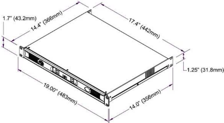
text_image
1.7" (43.2mm) 14.4" (366mm) 17.4" (442mm) 1.25" (31.8mm) 19.00" (483mm) 14.0" (356mm)
mXa-1502 • Operating Manual
LIMITED WARRANTY (USA ONLY)
(Other countries please contact your respective distributor or dealer.)
For units purchased in the USA, warranty service for this unit shall be provided by ASHLY AUDIO in accordance with the following warranty statement.
ASHLY AUDIO, an exertis|JAM business, warrants to the owner of this product that it will be free from defects in workmanship and materials for a period of FIVE years from the original-date-of-purchase, with the exception of touch-screen displays and motorized faders which are warranted for THREE years from the original-date-of-purchase.
ASHLY AUDIO will without charge, repair or replace at its discretion, any defective product or component parts upon prepaid delivery of the product to the ASHLY AUDIO factory service department, accompanied with a proof of original-date-of-purchase in the form of a valid sales receipt. This warranty gives you specific legal rights, and you may also have other rights, which vary from state to state.
EXCLUSIONS: This warranty does not apply in the event of misuse, neglect, or as a result of unauthorized alterations or repairs made to the product. This warranty is void if the serial number is altered, defaced, or removed. ASHLY AUDIO reserves the right to make changes in design, or make additions to, or improvements upon, this product without any obligation to install the same on products previously manufactured.
Any implied warranties, which may arise under the operation of state law, shall be effective only for FIVE years (THREE years for touch-screen displays and motorized faders) from the original-date-of-purchase of the product. ASHLY AUDIO shall be obligated to only correct defects in the product itself. ASHLY AUDIO is not liable for any damage or injury, which may result from, or be incidental to, or a consequence of, such defects. Some states do not allow limitations on how long an implied warranty lasts, or the exclusion, or limitation of incidental or consequential damages, so the above limitations or exclusions may not apply to you.
OBTAINING WARRANTY SERVICE:
For warranty service in the United States, please follow this procedure:
1) Contact the Ashly Service Department at 800-705-2102 or https://ashly.com/technical-support/to receive an RMA number. You must receive a RMA from the Service Department before sending your unit to Ashly.
2) Return the product to ASHLY AUDIO freight prepaid, with a written statement describing the defect and application that the product is used in. ASHLY AUDIO will examine the product and perform any necessary service, including replacement of defective parts, at no further cost to you.
3) Ship your product to:
ASHLY AUDIO
Service - RMA (insert RMA#)
847 Holt Road
Webster, NY 14580-9103
ASHLY AUDIO 847 Holt Road Webster, NY 14580-9103, USA
Phone: (800) 705-2102 Fax: (585) 872-0739
www.ashly.com
An exertis | JAA business
©2021 Ashly Audio. All rights reserved worldwide.
All features, specifications, and graphical representations are subject to change or improvement without notice.

mxa r6-0525
