CVM-WM200A - Microphone Comica - Free user manual and instructions
Find the device manual for free CVM-WM200A Comica in PDF.


User questions about CVM-WM200A Comica
0 question about this device. Answer the ones you know or ask your own.
Ask a new question about this device
Download the instructions for your Microphone in PDF format for free! Find your manual CVM-WM200A - Comica and take your electronic device back in hand. On this page are published all the documents necessary for the use of your device. CVM-WM200A by Comica.
USER MANUAL CVM-WM200A Comica
UHF Wireless Microphone
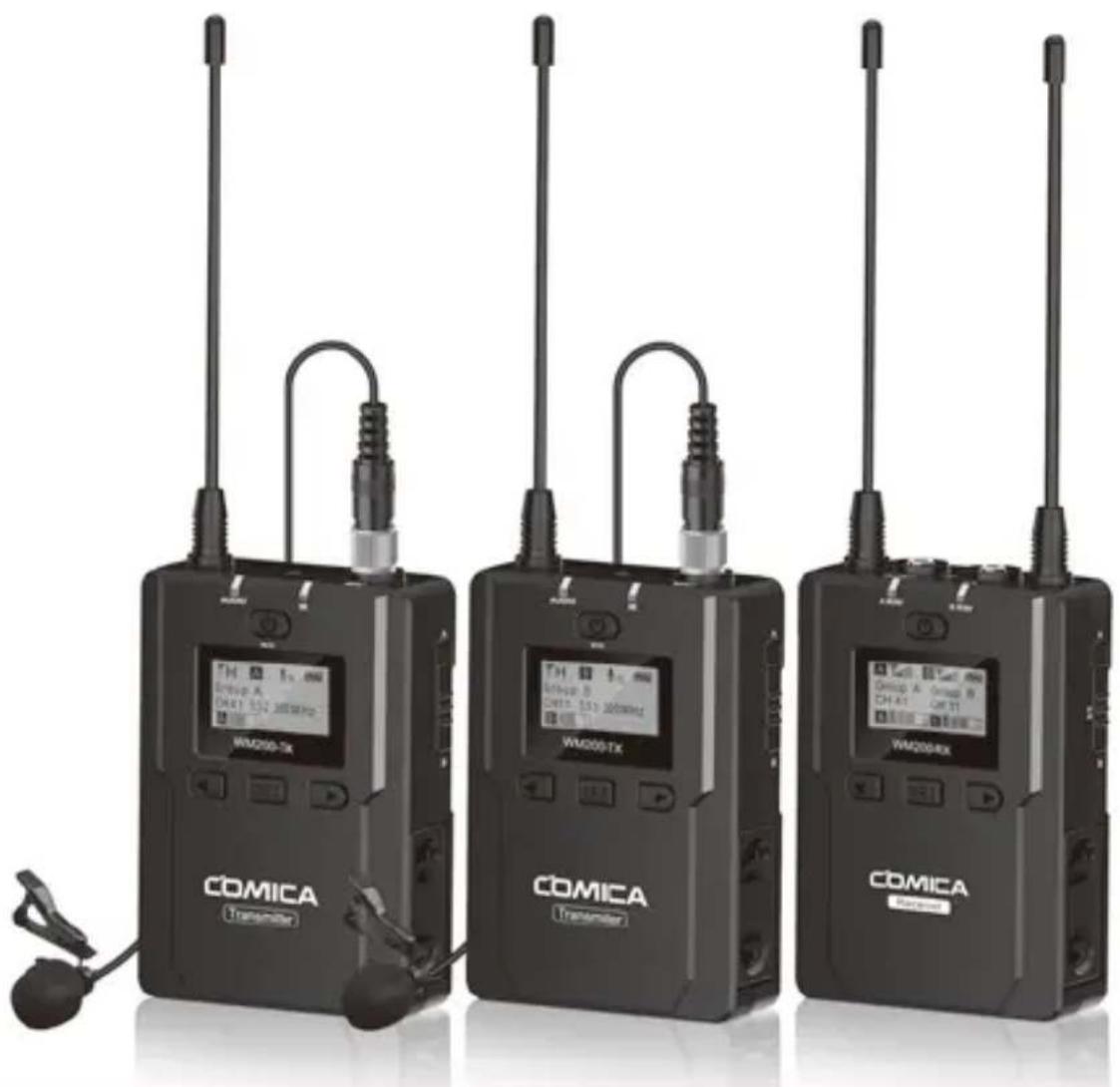
natural_image
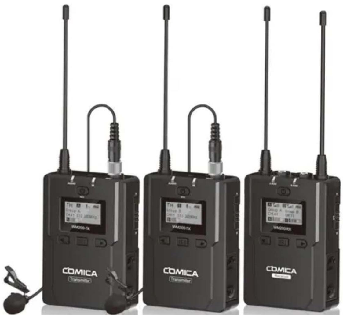
Three black COMICA wireless transmitters with visible signal lines and earphones, no text or symbols on devices themselves.USER MANUAL
Foreword
Thanks for purchasing COMICA WM200 UHF wireless microphone. To ensure a good using experience and customers' physical safety, please carefully read this instruction before using and properly assemble and operate.
Main Features
. Dual Transmitters Triggered by One Receiver, A/B Double Group Options
. Quick A/B/A+B Group Switch
. Used for Multiple Devices Working Together
. Working Distance is Up to 120m (120m in Open Area, 80m in Area with Obstacle)
. LCF Low Cut Filtering Mode
. Auto-scanning for Quick Channel Selection
. IR Sync
. Adjustable RF Signal Strength
. AA Batteries and External Power Supply
. Audio Dynamic Display Bar
. 16 Levels Volume Adjustment
. Optional Language
. Transmitter Power Monitor
. Output Modes Mono/Stereo Switch
. Low-consumption, Super-long Standby Time
. Lattice LCD Display, High Resolution
. Full Metal Manufacturing, Excellent Shielding
Notice
Transmitter should be placed at a distance more than 10cm from Receiver. When the distance is less than 10cm, Receiver's wireless signal receiving part will take protect action to shut down the receiving wireless signal, then audio may be intermittent, which is normal
When using auto IR sync, please stay within 30cm, otherwise the signal may be too weak and the sync will not be successful
In the case of stereo/mono mode switch, please preset the mode before using to avoid the transient interference caused by switching during usage
When there is any need for long time using, external power bank is better for power supplying instead of using AC-DC power to avoid noise problem
The antenna will affect the working distance. Please protect the antenna and avoid any man-made damage
The working distance will be affected by the surrounding environment. Please try to keep the environment open without interference during usage, and close the WIFI of the device itself
When using this product in a short distance, it is recommended to set RF strength at 'LOW' to reduce the power consumption
For smartphone shooting, customers need to separately purchase a TRS-TRRS audio cable adapter, and remember to set the mobile phone mode to 'Flight Mode' for avoiding incoming call interference (It does not support the original recording system of some android systems, the third-party APP is recommended to be used in this case)
Please keep this product in dry environment
Do not expose the device in rain or humid environment, otherwise there will be a danger of short circuit
Package Contents
Main Parts:
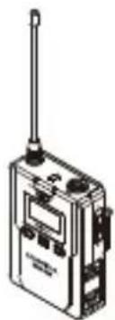
natural_image
Illustration of a walkie-talkie device with antenna and control panel (no text or symbols visible)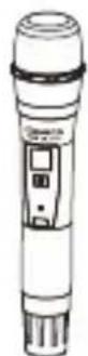
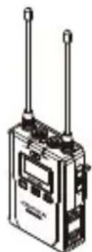
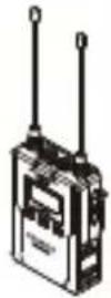
natural_image
Illustration of a walkie-talkie device with two antennas and a digital display (no text or symbols visible)Lavalier Transmitter (TX) Hand-held Transmitter (HTX) Receiver (RX)
Multiple Selections:
$$ \mathrm{WM200(A)} = 2 \mathrm{TX} + \mathrm{RX} $$
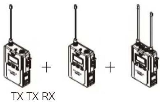
text_image
TX TX RX$$ \mathrm{WM200(C)} = \mathrm{TX} + \mathrm{RX} $$
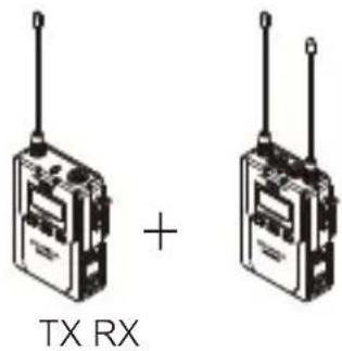
text_image
TX RX +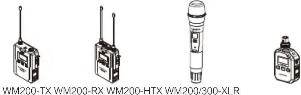
text_image
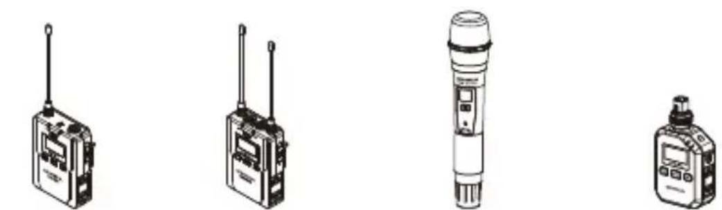
WM200-TX WM200-RX WM200-HTX WM200/300-XLR
For the method of WM200/300-XLR using, please refer to the user manual that comes with the product
Accessories:
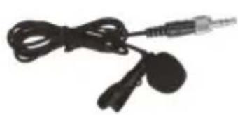
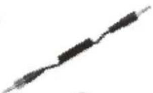
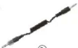
① 3.5mm Mic Audio Input Cable
② 3.5mm-3.5mm Audio Output Cable
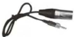
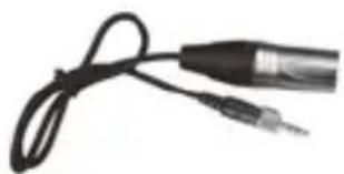
③ 3.5mm-XLR Audio Output Cable
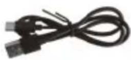
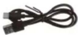
④ USB-C Charging Cable
⑤ Belt Clip
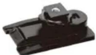
⑥ Cold Shoe Mount
⑦ Wind Muff
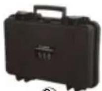
⑧ Portable Box
⑨ User Manual
⑩ Warranty Card
natural_image
Close-up of a black cord with two earphones and a connector (no text or symbols visible)①
natural_image
Pure electrical circuit lines without any symbols②
natural_image
Close-up of a black audio jack with two leads, no visible text or symbols③
4
5
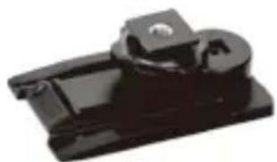
natural_image
Close-up of a black plastic mechanical component with a circular hole and rectangular base (no visible text or symbols)⑥7

O
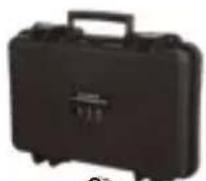
8
⑨
⑩

The accessories of each combination include:
$$ \mathrm{WM200(A)} = \textcircled {1} \mathrm{x2} + \textcircled {2} 3 \neq 6 7 8 9 + \textcircled {5} \mathrm{x3} + \textcircled {\bigcirc} + \textcircled {\bigcirc} \mathrm{x2} + \textcircled {\bigcirc} + \textcircled {\bigcirc} + 1 0 $$
$$ \mathrm{WM200(C)} = \textcircled {1} + \textcircled {2} + \textcircled {3} + \textcircled {4} + \textcircled {5} x 2 + \textcircled {6} + \textcircled {7} 8 + 9 \bigcirc + \bigcirc + 1 0 $$
Components and Instruction
Components
Lavalier Transmitter (TX)
① Antenna
② Matching Status Indicator
③ Sound Status Indicator
④ Power / Muting Button
⑤ LCD Screen
⑥ Function Selection Button -
⑦ SET Function Menu
⑧ Function Selection Button +
⑨ IR Sensor
⑩ MIC / LINE IN External Input
⑪ Group Selection Switch
⑫ Battery Tray
13 1/4 Mounting Hole
⑭ Belt Clip
⑮ USB-C Charging Socket
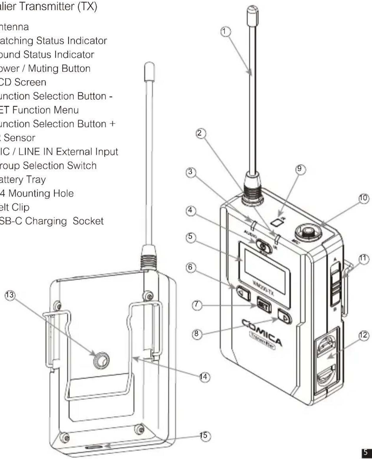
text_image
Lifier Transmitter (TX) ntenna atching Status Indicator bound Status Indicator power / Muting Button CD Screen unction Selection Button - ET Function Menu unction Selection Button + Sensor IC / LINE IN External Input group Selection Switch battery Tray 4 Mounting Hole belt Clip SB-C Charging Socket 13 2 3 4 5 6 7 8 9 10 11 12 14 15Hand-held Transmitter (HTX)
① Microphone
② LCD Display
③ Power / Muting Button
④ IR Screen
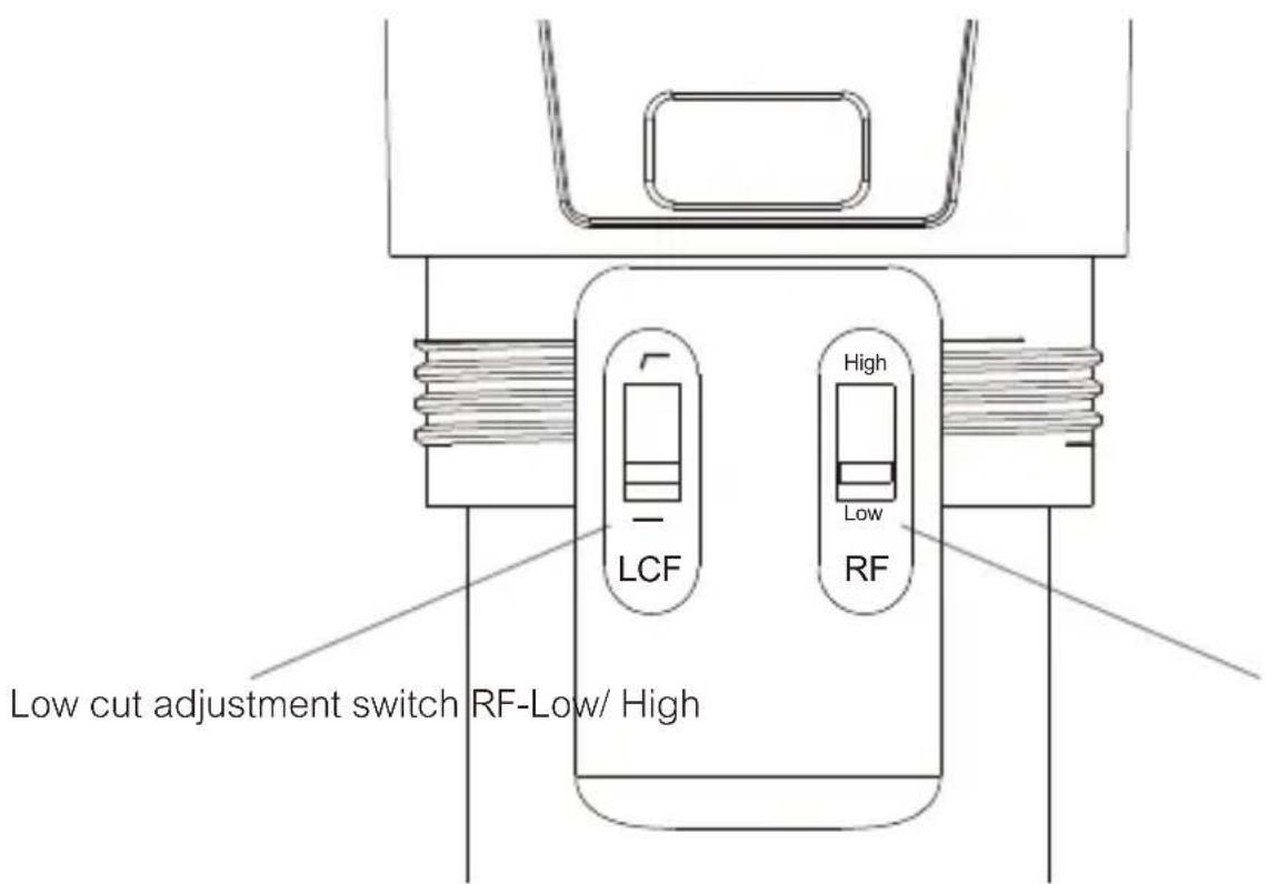
⑤ Low Cut Filter/Normal Audio Switch
⑥ Signal Strength "High/Low" Switch
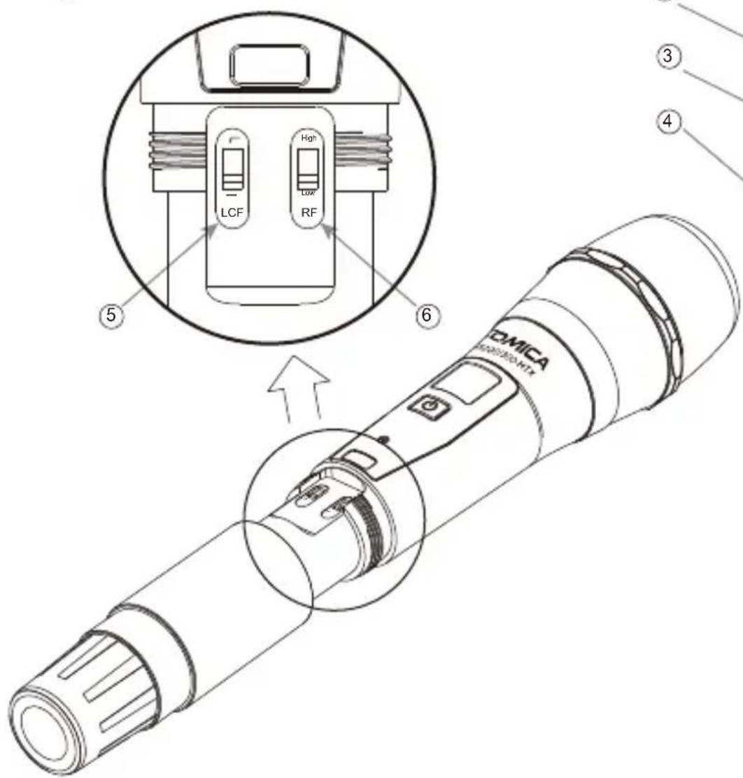
text_image
DMICA LCF High Low RF ⑤ ⑥ ③ ④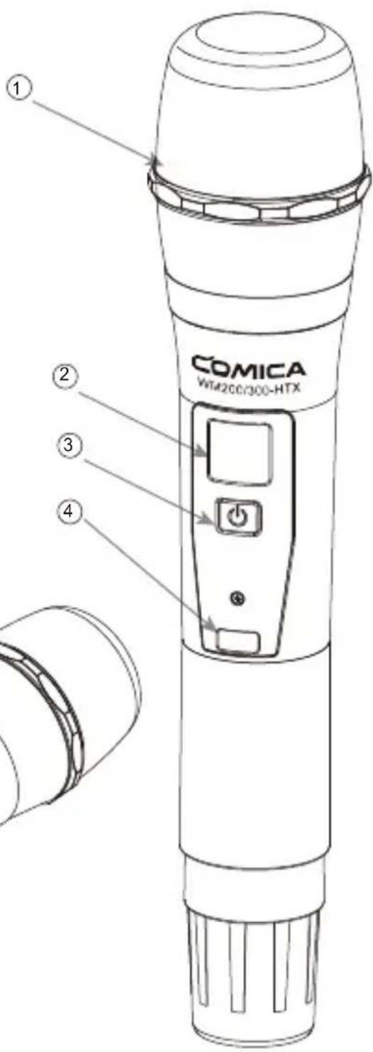
text_image
① COMICA Wi4200/300-HTX ② ③ ④Receiver (RX)
① Group A Antenna
② Group B Working Status Indicator
③ Group A Working Status Indicator
④ Power Switch
⑤ LCD Screen
⑥ Function Selection Button -
⑦ SET Function Menu
⑧ Function Selection Button +
⑨ 3.5mm Audio Output Socket
⑩ IR Sensor
⑪ 3.5mm Monitoring Socket
⑫ Group B Antenna
⑬ Group Selection Switch
⑭ Battery Tray
⑮ Belt Clip
⑯ USB-C Charging Socket
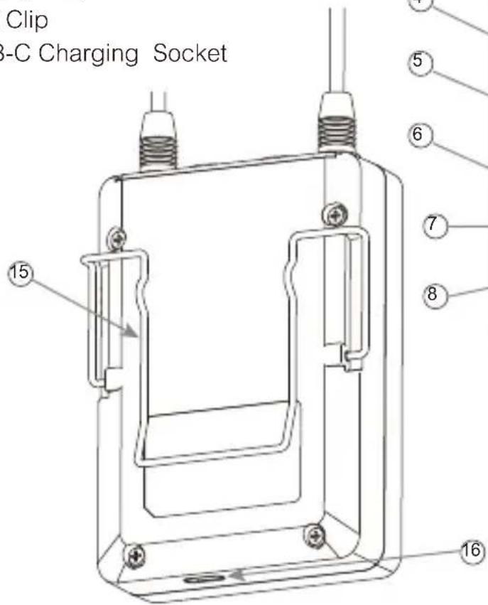
text_image
Clip 3-C Charging Socket ⑮ ⑤ ⑥ ⑦ ⑧ ⑯ ⑯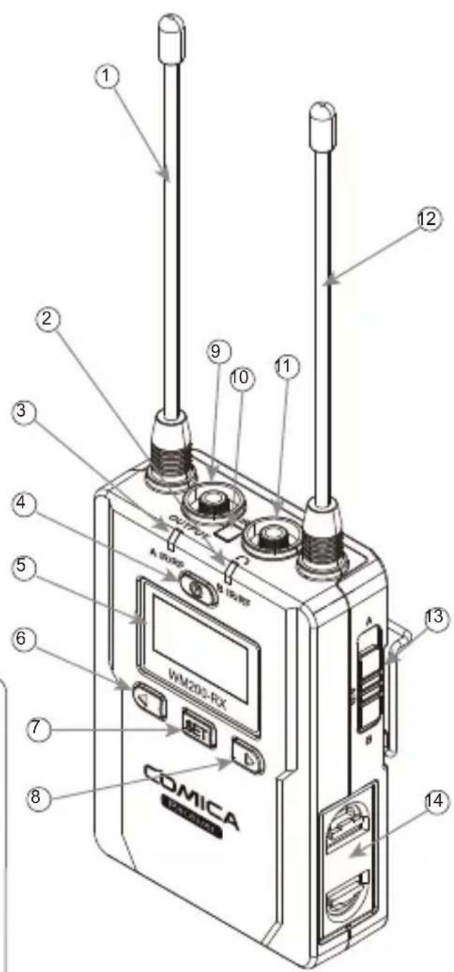
text_image
1 2 3 4 5 6 7 8 COMICA A micro WM205-RX B CET D E F G H I J K L M N O P Q R S T U V W X Y Z A B C D E F G H I J K L M N O P Q R S T U V W X Y ZFunction Button Instruction
Lavalier Transmitter / Receiver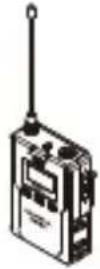 | Power / Muting Button | Long Press | Power On / Off |
| Short Press | Muting Mode (This function is only for transmitter, when the mute function is turned on and the screen is lighted up) | ||
| SET Function Menu | Long Press | Enter the function adjustment menu | |
| Short Press | 1. Confirm the selected function2. Exit the function adjustment menu | ||
 | + Button | Short Press | Function Adjustment (+) |
| - Button | Short Press | Function Adjustment (-) | |
Hand-held Transmitter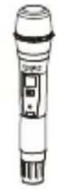 | Power / Muting Button | Long Press | Power On / Off |
| Short Press | Muting Mode (Only goes into effect when the screen lights up) | ||
“Low cut/ Normal” Sound Switch 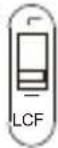 | Push-up | Low cut | |
| Push-down | Normal | ||
Signal Strength “High/Low” Switch 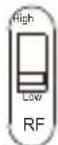 | Push-up | Signal strength--high | |
| Push-down | Signal strength--low |

Signal strength high / low switching effect:
With high signal strength, the wireless working distance is up to 80-120M, high power consumption, battery life is short; With low signal strength, the wireless working distance is up to 30-60M, low power consumption, the battery can be used for a long time.

Low cut function:
Appropriately remove the low frequency part of the sound, reduce the ambient noise of the low frequency part, to make sound more clean and clear.
Indicator Light Instruction
| Transmitter | AUDIO | Green Light Keeps on | Normal Recording Status (This state is only for the transmitter, when the channel matches successfully, then the receiver can pick up the sound) |
| Red Light Keeps on | Muting Mode | ||
| Red Light Flickers | Low-power reminder | ||
| IR | Green Light Keeps on | Channel matches (No matter the channel matched or not) | |
| Red Light Flickers | Channel is matching...... (only for IR Sync) | ||
| Receiver | A IR/RF B IR/RF | Green Light Keeps on | Normal working status after the channel matched |
| Green Light Flickers | Channel match failed | ||
| Red Light Flickers | Channel is matching...... (only for IR Sync) | ||
| Low-power reminder | |||
| Red Light keeps on | Group closed |

A IR/RF: Group A Working Status Indicator
B IR/RF: Group B Working Status Indicator
Installation and Usage
Lavalier Transmitter
- Install two AA batteries into the battery tray according to the positive and negative electrode. It supports external power-supplying through USB-C Plug
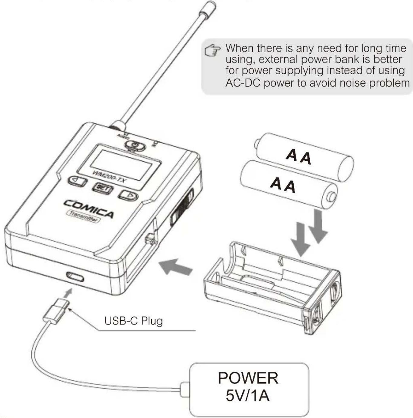
text_image
When there is any need for long time using, external power bank is better for power supplying instead of using AC-DC power to avoid noise problem COMICA Transmitter WM200-TX SET D USB-C Plug AA AA POWER 5V/1A- Insert the 3.5mm audio input cable into MIC socket
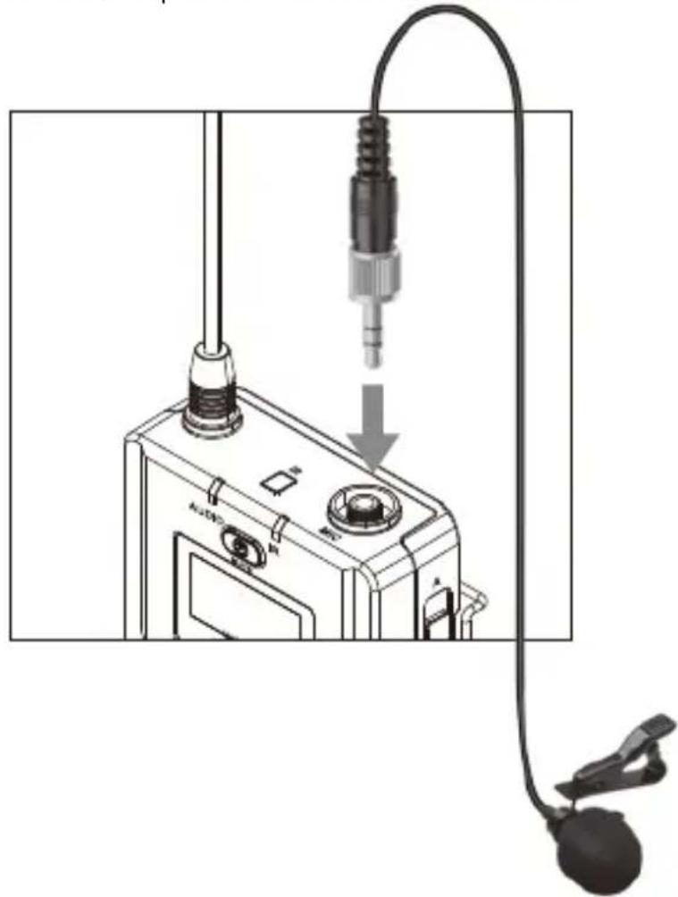
natural_image
Diagram of a audio testing device with a plug inserted into a microphone, connected to a cable (no text or symbols visible)- Long press the power button to turn on the transmitter
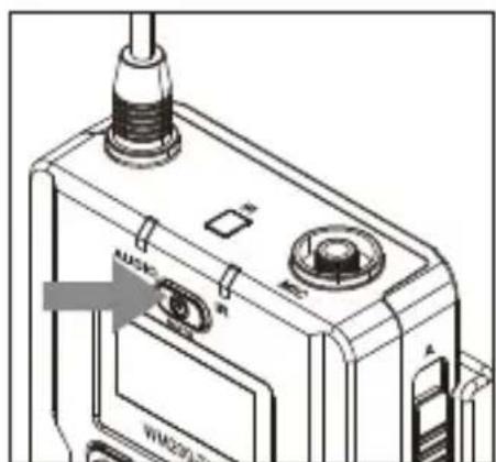
natural_image
Technical line drawing of a device with labeled ports and a central screen (no readable text or symbols)- Place the MIC at the audio source and check the working status according to the volume indicator on the screen
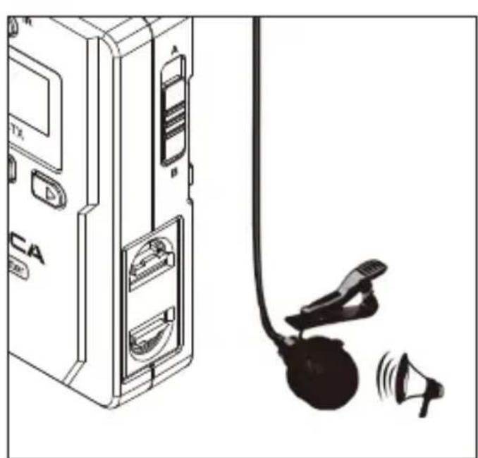
natural_image
Illustration of a device with labeled ports and a microphone emitting sound waves (no text or symbols present)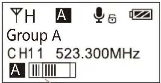
text_image
Group A CH1 1 523.300MHzAudio Dynamic Display Bar
- Insert the belt clip to the connection hole
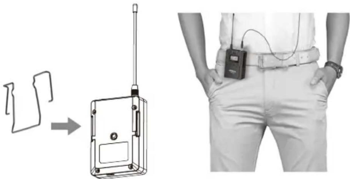
natural_image
Diagram showing a device with a left-side outline transforming into a rectangular device, and a person wearing a bandage holding an electronic device (no text or symbols present)- After the channel matched with the receiver, it can be used

Please refer to screen operation instruction for channel matching.
Hand-held Transmitter
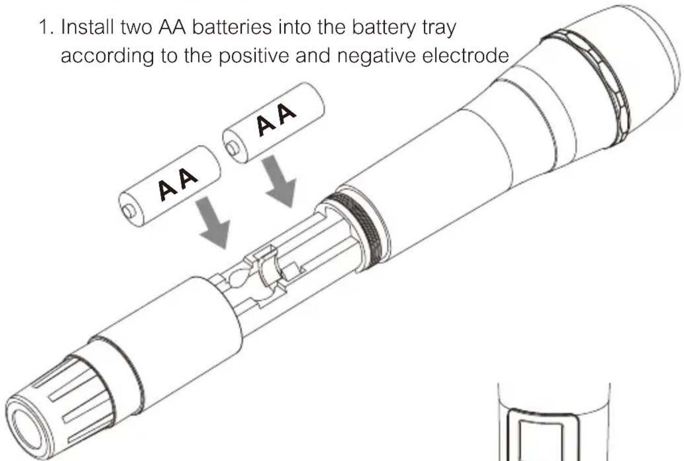
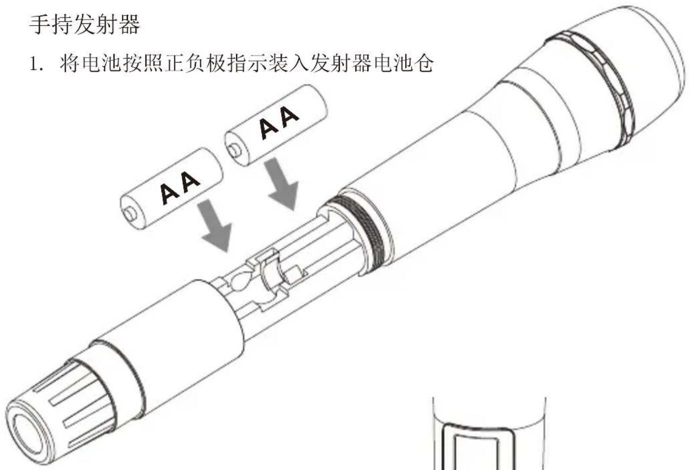
- Install two AA batteries into the battery tray according to the positive and negative electrode
text_image
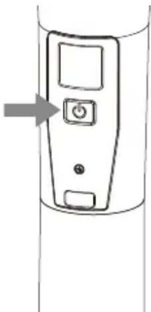
1. Install two AA batteries into the battery tray according to the positive and negative electrode AA AA- Long press the button switch to turn on the hand-held transmitter
natural_image
Diagram of a vertical device with two buttons and an arrow pointing to the left side (no text or symbols)- After the channel matched with the receiver, it can be used

Please refer to screen operation instruction for channel matching.
Receiver
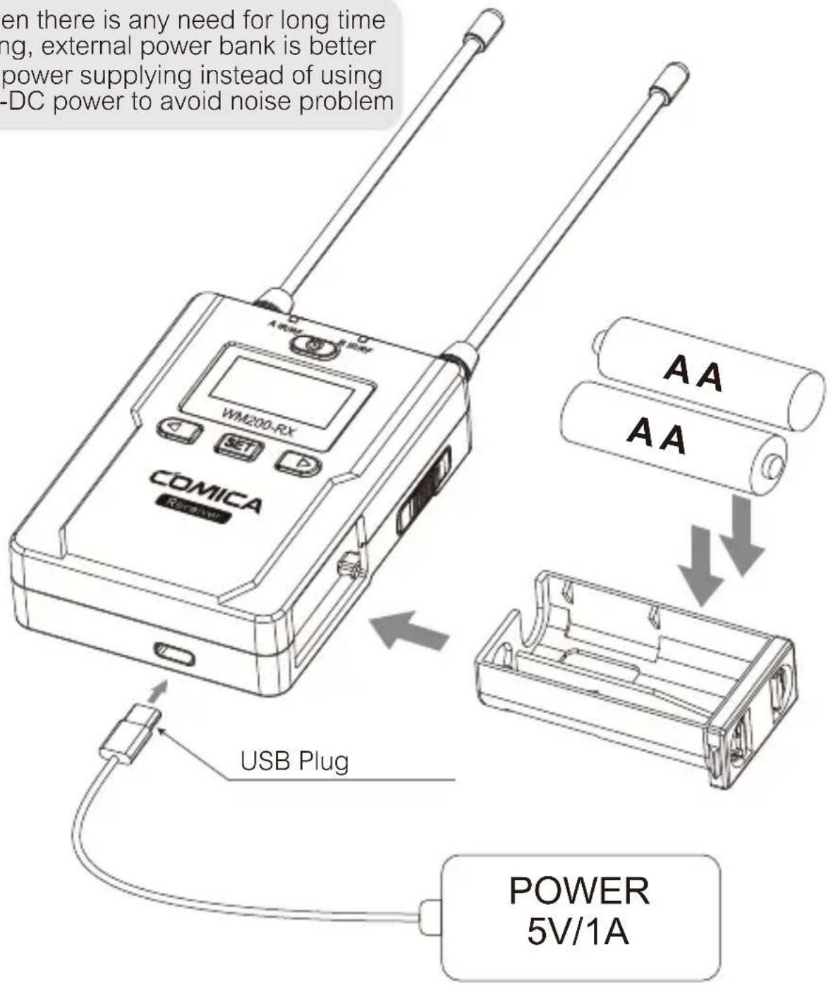
- Install two AA batteries into the battery tray according to the positive and negative electrode. It supports external power-supplying through USB-C Plug

When there is any need for long time using, external power bank is better for power supplying instead of using AC-DC power to avoid noise problem
text_image
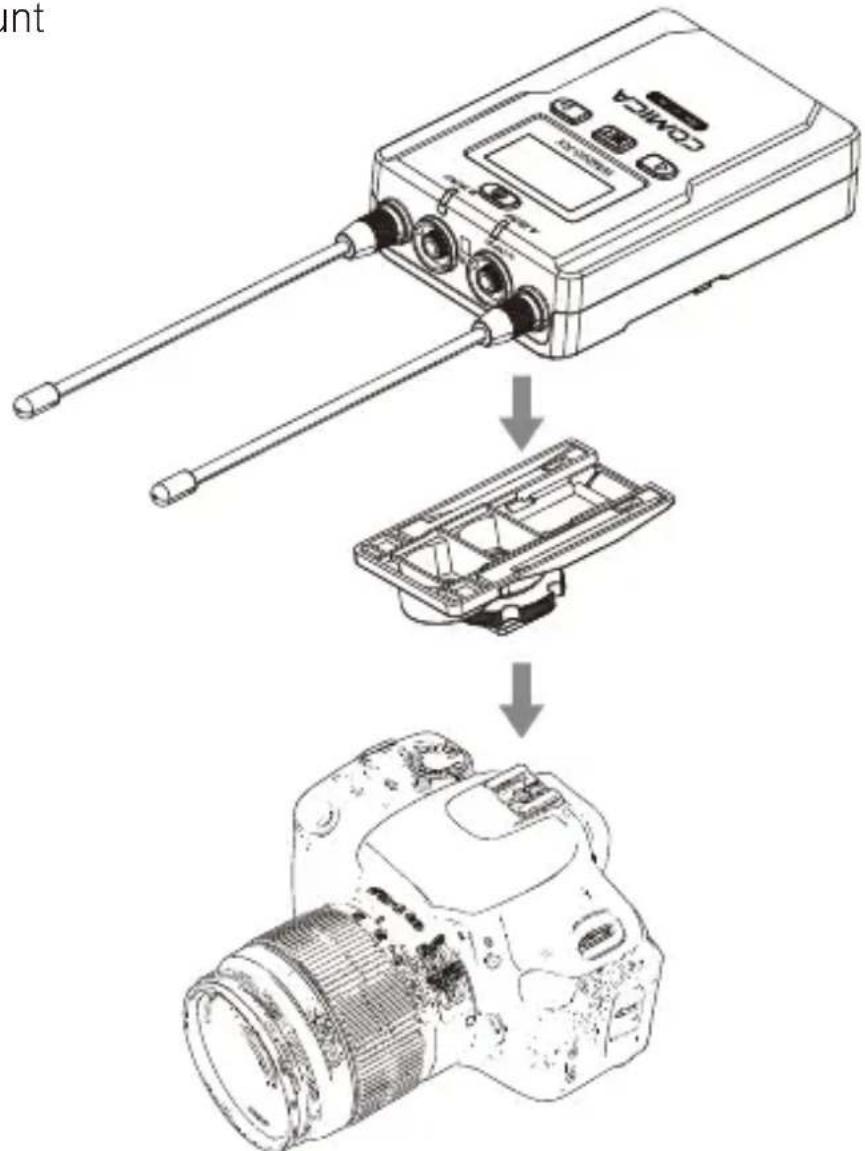
en there is any need for long time ng, external power bank is better power supplying instead of using -DC power to avoid noise problem A RAM B RAM WM200-RX SET COMICA Power AA AA USB Plug POWER 5V/1A- Connect the receiver to the video device through the Cold Shoe Mount
text_image
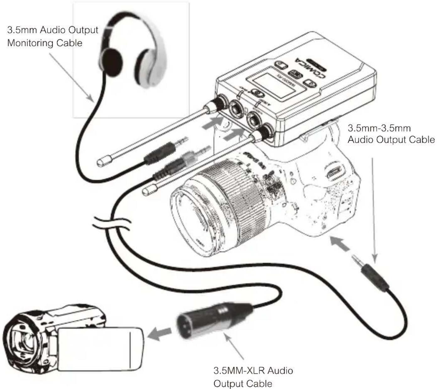
unt- Connect one end of the 3.5mm-3.5mm audio OUTPUT cable to the OUTPUT port of WM200RX and another end to the AUDIO INPUT port of the camera or camcorder. Insert the headphone into the 3.5mm monitoring port for real-time monitoring and then long press power button to trun on the receiver.

Most DSLR cameras has 3.5mm port, if you use the XLR camcorder, you need to use the 3.5mm-XLR audio output cable.
text_image
3.5mm Audio Output Monitoring Cable 3.5mm-3.5mm Audio Output Cable 3.5MM-XLR Audio Output Cable- After the channel matched with the receiver, it can be used

Please refer to screen operation instruction for channel matching.
Screen Display and Operation Instruction
Lavalier Transmitter
Screen Display Instruction
text_image
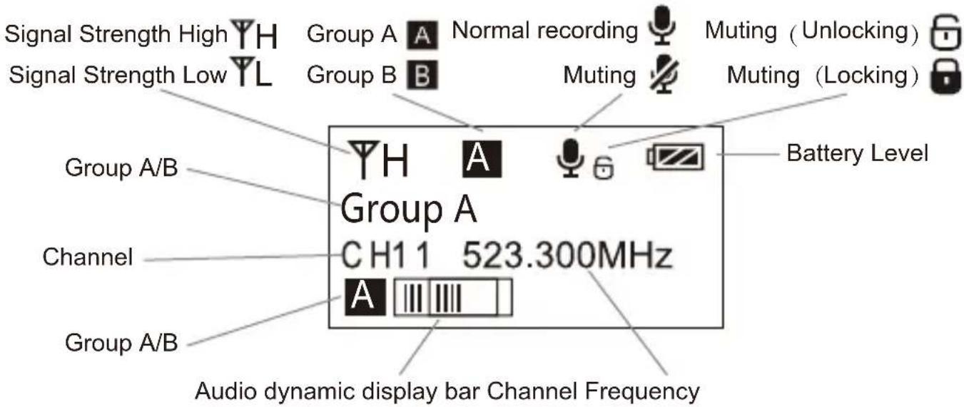
Signal Strength High Signal Strength Low Group A Group B Group A/B Channel Group A/B Group A Normal recording Muting (Unlocking) Muting (Locking) Battery Level CH1 1 523.300MHz Audio dynamic display bar Channel FrequencyOperation Instruction
1. Group A/B Selection
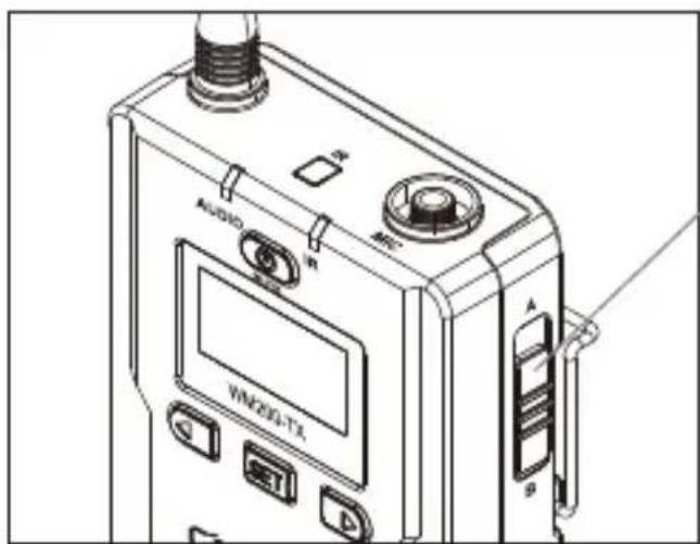
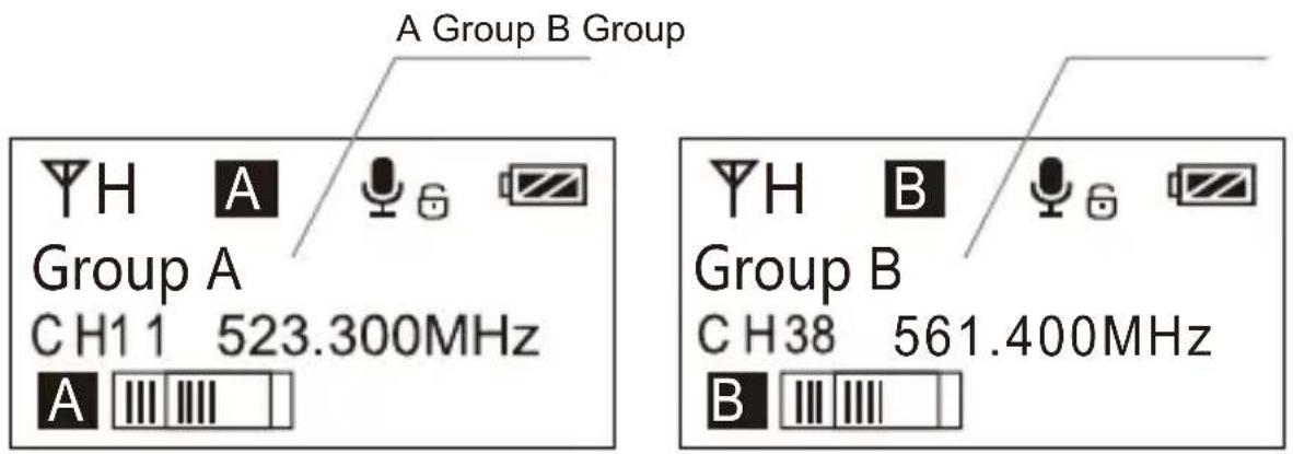
1.1 Use A/B Group selection switch to select the group, when push up to A, Group A truns on; when push to B, Group B truns on. You could choose Group A or Group B according to your demand.
text_image
AUDIO VIN203-TX A BA/B Group Selection Switch
text_image
A Group B Group Group A CH1 1 523.300MHz A Group B CH38 561.400MHz B2. Manually Adjust the Channel of Transmitter
2.1 Long press SET button to CH setting display page
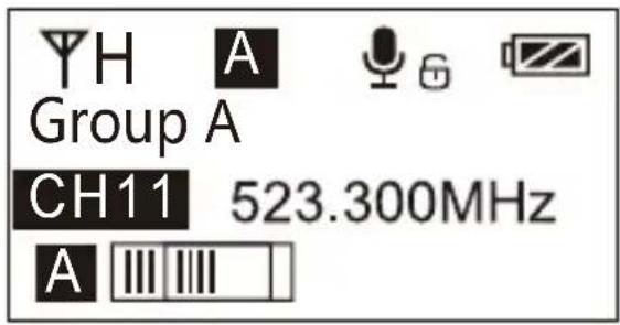
text_image
YH A Group A CH11 523.300MHz A III III2.2 Short press ◀ ▶ button to select the channel
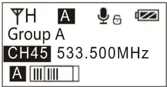
text_image
YH A Group A CH45 533.500MHz A2.3 Short press SET button to confirm

text_image
YH A Group A CH45 533.500MHz A3. MIC/LINE IN Input Mode Adjustment
3.1 Press ◀ ▶ button to 'Input Setting' display page
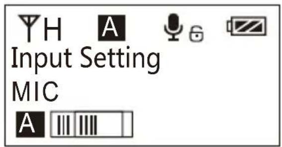
text_image
Input Setting MIC3.2 Long press SET button to ' Input Setting ' display page
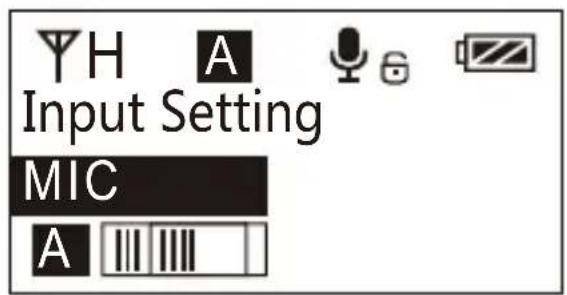
text_image
Input Setting MIC3.3 Press ◀ ▶ button to select ' Mic/ Line in ' input mode
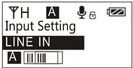
text_image
Input Setting LINE IN3.4 Short press SET button to confirm

Mic mode is for Microphone input;
Line in mode is for external audio input, such as smartphone music player.
Selecting the corresponding input mode will bring you a better audio effect.
4. Low Cut Filter 'Low/High/OFF' Adjustment
4.1 Press ◀ button to 'Low Cut Filter' display page
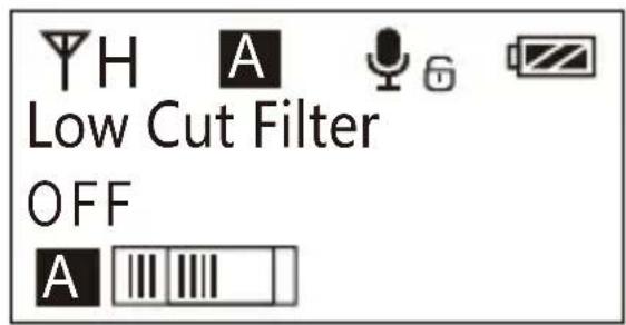
text_image
YH A Low Cut Filter OFF A4.2 Long press SET button to enter ' Low Cut Filter' display page
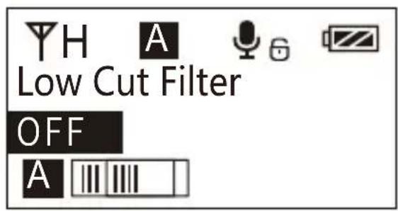
text_image
YH A Low Cut Filter OFF A4.3 Press ▶ button to select LCF ' Low/High/OFF '
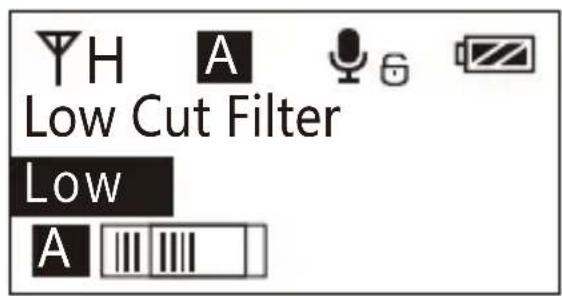
text_image
YH A Low Cut Filter Low A4.4 Short press SET button to confirm
The LCF function will remove the low-frequency part of the audio source, such as the sound of wild insects and the noise of the crowd, and the main audio source will be thinner. When the LCF function is turned off, the original sound will be restored, and the main sound source will be thicker. You can adjust according to actual needs.
5. Transmitting Signal Strength 'High/Low' Adjustment
5.1 Press ◀ button to "RF Power Setting" display page
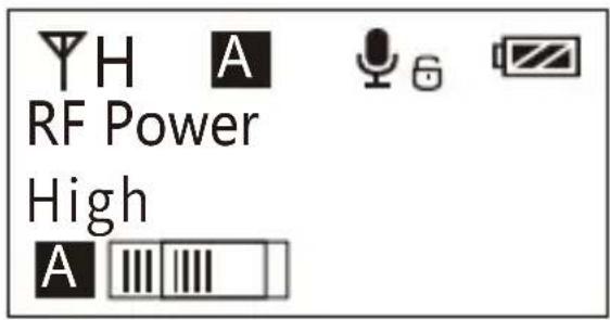
text_image
YH A RF Power High A III III5.2 Long press SET button to enter ' RF Power Setting ' display page
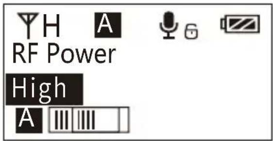
text_image
YH A RF Power High A5.3 Press ◀ button to adjust the transmitting signal strength
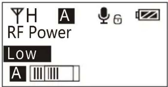
text_image
YH A RF Power Low A5.4 Short press SET button to confirm
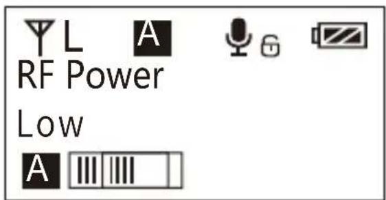
text_image
Y L A RF Power Low A III III6. Muting Mode On/ Off
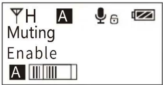
6.1 Press ◀ button to 'Muting' display page
text_image
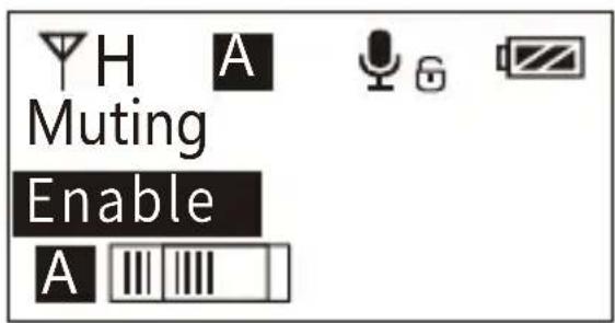
H A Muting Enable A6.2 Long press SET button to enter 'Muting' display page
text_image
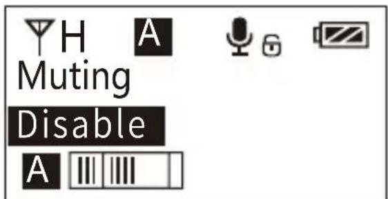
H A Muting Enable A6.3 Press ◀ button to select Muting mode on/off
text_image
H A Muting Disable A6.4 Short press SET button to confirm

text_image
H A Muting Disable A
When set to 'Disable', the muting function cannot be used, the icon is:


When set to 'Enable', the muting function works, the icon is:


The muting mode can be controlled only when the screen is on, press any button to light the screen and then press the SET button to switch the muting mode.
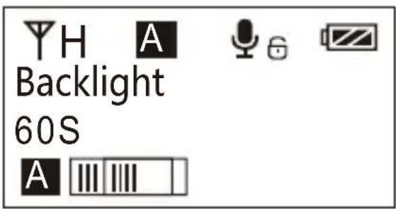
7. Backlight ‘ Lighting Time/Turn Off ’ Adjustment
8.1 Short Press

button to 'Backlight Mode' display page
text_image
YH A Backlight 60S A III III7.2 Long press SET
button to enter 'Backlight Mode' display page
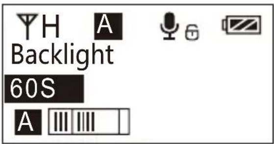
text_image
YH A Backlight 60S A7.3 Short press

button to adjust the backlight lighting time f for power saving
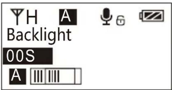
text_image
YH A Backlight 00S A7.4 Short press

button to confirm
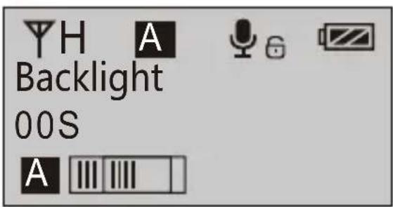
text_image
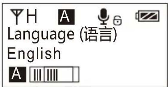
H A Backlight 00S A8. System Language
8.1 Short press ◀ ▶ button to 'Language' display page
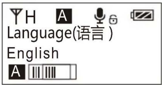
text_image
Language(语言) English8.2 Long press SET button to enter 'Language' display page
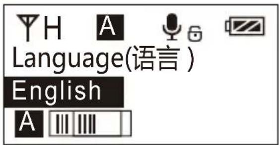
text_image
Language(语言) English A8.3 Short press ◀ button to select language
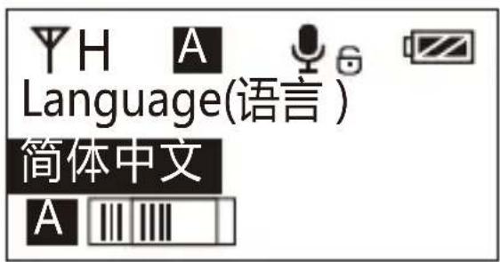
text_image
YH A Language(语言) 简体中文 A8.4 Short press SET button to confirm
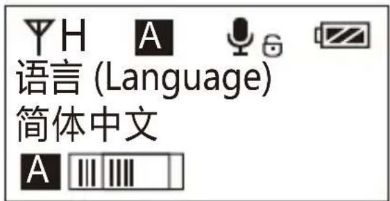
9.3 Short press ◀ button to select whether to restore factory Setting
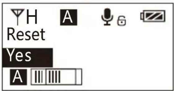
text_image
H Reset Yes A9.4 Short press SET button to confirm and restore factory setting
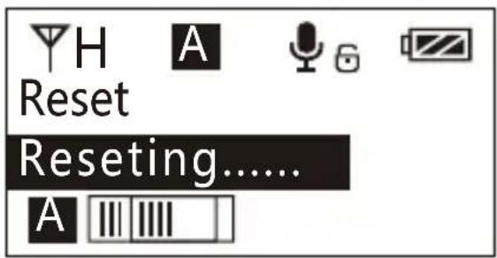
text_image
Reset Reseting...... A10. Version
10.1 Press ◀ button to 'Version' display page to check the version
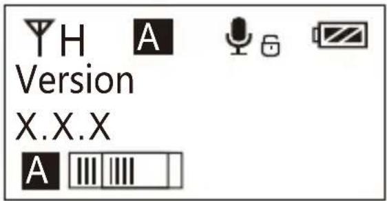
text_image
Version X.X.XHand-held Transmitter Screen Display Instruction
Normal recording mode
Group A/B
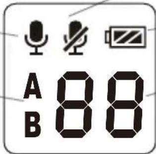
text_image
A 88 BBattery Level
Channel
Operation Instruction
1. Turn on and Muting Mode Switch
1.1 Long press 🎨 switch button for 2 seconds to turn on or off
1.2 When the transmitter turned on, short press the ⏻ button to select muting mode
Normal recording Muting
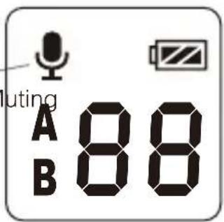
text_image
luting A 88 B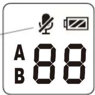
text_image
A 88 B
The muting mode can be controlled only when the screen is on, press any button to light the screen and then press the button to switch the muting mode.

2. Pair Through Infrared Sync
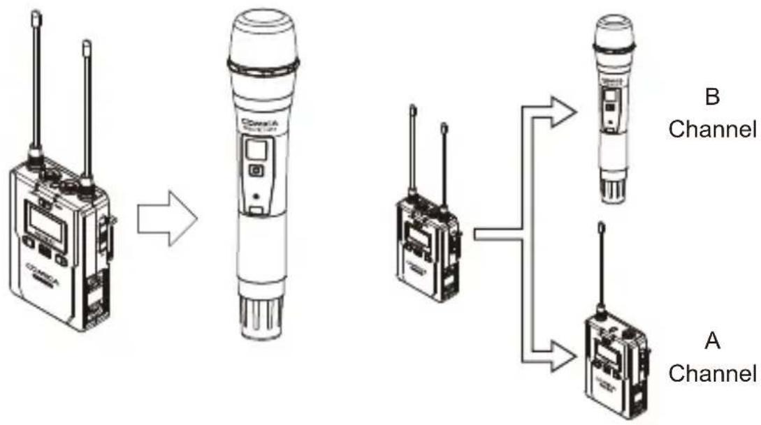
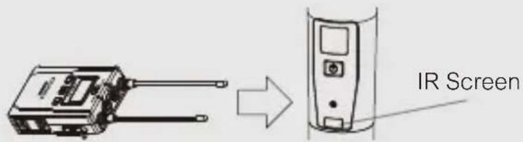
2.1 Set the channel through infrared sync
flowchart
graph LR
    A["Radio Station 1"] --> B["Radio Station 2"]
    B --> C["Walkie-talkio 1"]
    B --> D["Walkie-talkio 2"]
    C --> E["Signal to Channel B"]
    D --> F["Signal to Channel A"]

The hand-held transmitter defaults to channel B, and you can set the group and channel through the receiver (For example, If Group A of the receiver is used for the matching, after matched, it will be: Group A CHXX; If Group B of the receiver is used for the matching, after matched, it will be: Group B CHXX)
When the hand-held transmitter and the lavalier transmitter are used together, you should set them to different group

During matching, don't shield the infrared receiving screen of the transmitter
text_image
IR Screen2.2 Function switch
text_image
Low cut adjustment switch RF-Low/ High LCF High Low RFReceiver
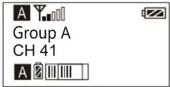
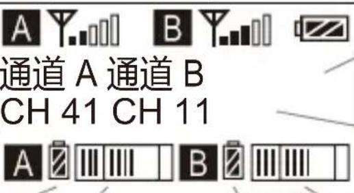
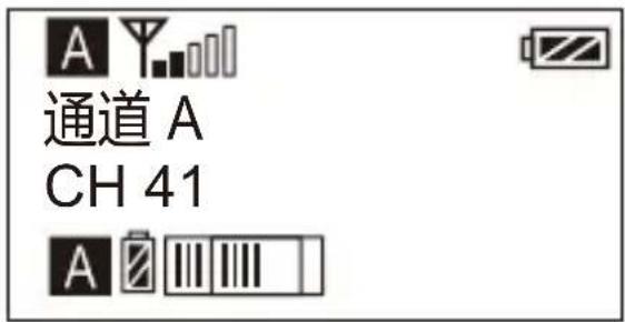
Screen Display Instruction
Group A Signal Strength Display Bar Group B Signal Strength Display Bar
Battery Level
Group A Group B

Group A Group B
CH 41 CH 11
Channel of Group A Chan

Group A transmitting battery Group B Transmitting battery
Group A Receiving Audio Status Indication Group B Receiving Audio Status Indication
Operation Instruction
1. A、B or A+B Group Selection Switch
1.1 Select the group using A, B and A+B group selection switch
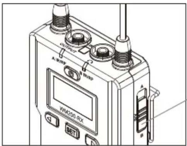
text_image
OUTPUT A/RBP B/RBP WM200-RX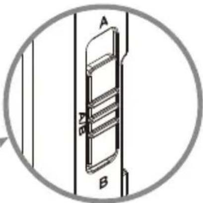
natural_image
Technical line drawing of a mechanical component with labeled parts A and B, enclosed in a circular frame (no text or symbols beyond labels)A、B or A+B Group Selection Switch
text_image
A Group A CH 41 A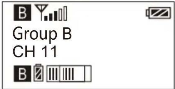
2. Manually Adjust the Channel of Group A/ Group B
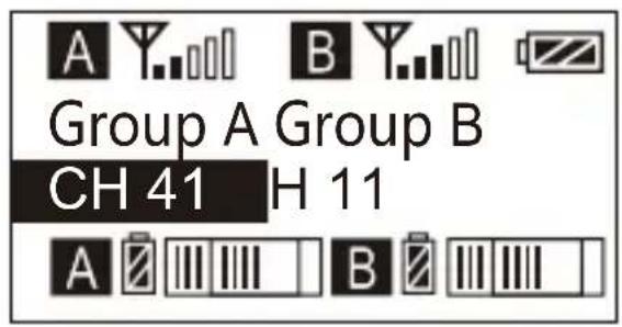
2.1 Long press SET button to 'CH' display page, short press again for Group A/Group B switch
text_image
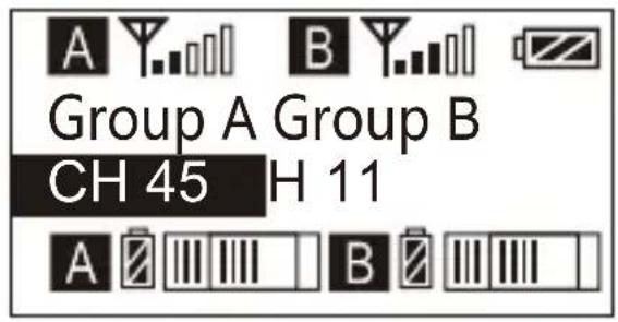
A Y B Group A Group B CH 41 H 11 A B2.2 Short press ◀ button to select the group
text_image
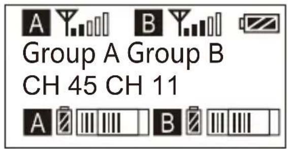
A Y. B Y. Group A Group B CH 45 H 11 A B2.3 Short press SET button to confirm
text_image
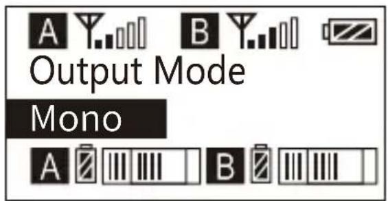
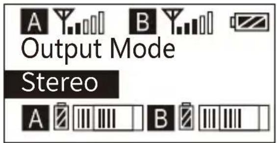
A Y B Group A Group B CH 45 CH 11 A B3. Audio Output Mode ‘Stereo/Mono’ Adjustment
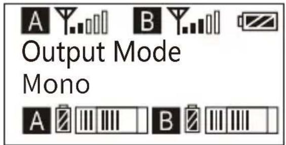
3.1 Press ◀ button to 'Output Mode' display page
text_image
A Y..B Y..B Output Mode Mono A ̅ ̅ ̅ ̅ ̅ ̅ ̅ ̅ ̅3.2 Long press SET button to 'Output Mode' display page
text_image
A Y. B Y. Output Mode Mono A Ⅱ Ⅲ Ⅳ B Ⅱ Ⅲ Ⅳ3.3 Press ◀ button to select 'Mono/ Stereo' Output Mode, Short press SET button to confirm
text_image
A Y B Y Output Mode Stereo A B
When set to a separate A channel or B channel, the output can only be MONO mode
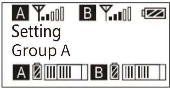
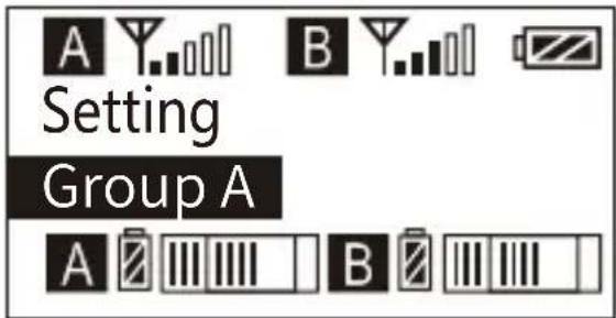
4. Group A/B Function Setting
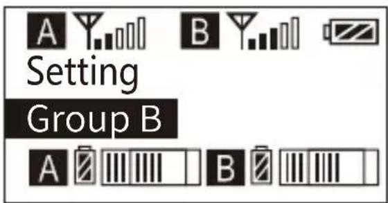
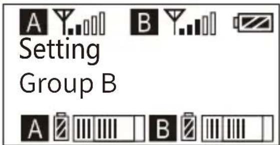
4.1 Press ▶ button to 'Setting' display page
text_image
Setting Group A4.2 Long press SET button to 'Setting' display page
text_image
Setting Group A4.3 Press ◀ button to select Group A/B to edit
text_image
Setting Group B4.4 Short press SET button to confirm
text_image
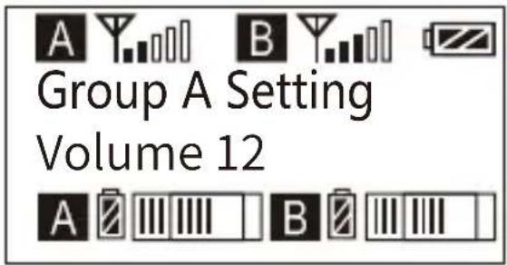
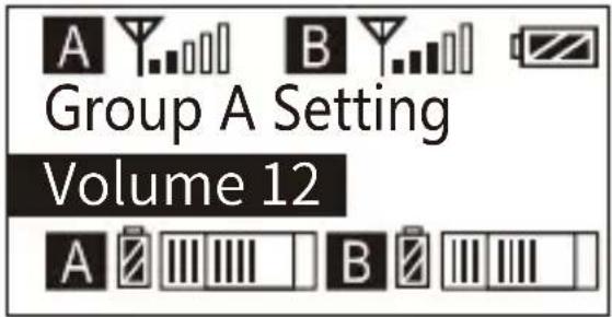
Setting Group B5. Group A/B Volume Adjustment
5.1 Short Press


button to 'Volume' display page
text_image
A Y B Y Group A Setting Volume 12 A Z III III | B Z III III |5.2 Long press

button to enter 'Volume' display page
text_image
A Y B Y Group A Setting Volume 12 A Z III III B Z III5.3 Short Press

button to adjust the volume
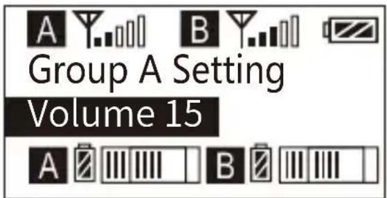
text_image
A Y..B Y..B Group A Setting Volume 15 A B B5.4 Short press

button to confirm
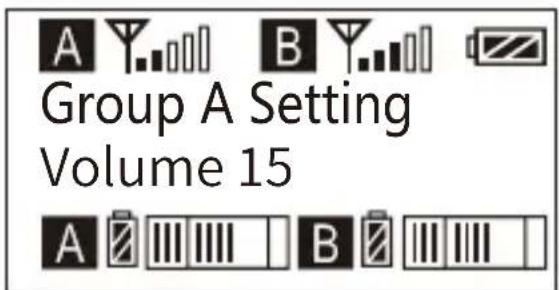
text_image
A Y. B Y. Group A Setting Volume 15 A Z III III I B Z III III I6. Group A/B Automatic Channel Scan
6.1 Short Press ◀ button to 'Auto Scan' display page
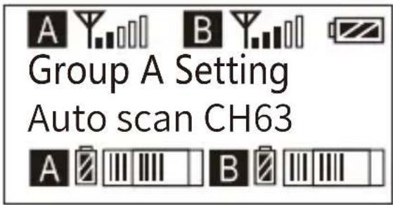
text_image
A Y B Y Group A Setting Auto scan CH63 A Z III III | B Z III III |6.2 Long press SET button to enter 'Auto Scan' display page, and short press ◀ button to select whether to auto scan
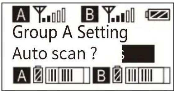
text_image
Group A Setting Auto scan ?6.3 Short press SET button to 'Scanning.....'
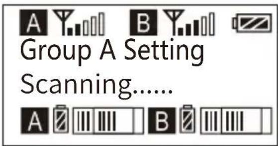
text_image
A Y B Y Group A Setting Scanning...... A Z III III I B Z III III I6.4 The best channel will be used after scanning Group A Setting
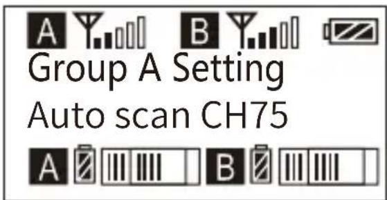
text_image
Group A Setting Auto scan CH757.Group A/B IR Sync
7.1 Short Press ◀ button to ' Group A/B Setting ' display page
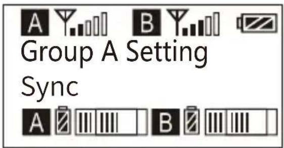
text_image
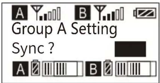
A Y B Y Group A Setting Sync A B B7.2 Long press SET button to enter ' Group A/B Setting' display page
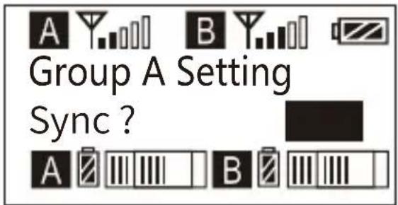
text_image
Group A Setting Sync?7.3 Short press ◀ ▶ button to select whether to sync
text_image
Group A Setting Sync ? A B7.4 Short press SET button to confirm sync

text_image
Group A Setting Matching......8. Backlight ‘ Lighting Time/Turn Off ’ Adjustment
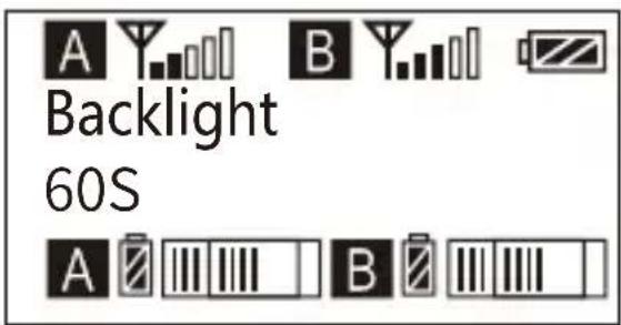
8.1 Short Press ◀ button to 'Backlight Mode' display page
text_image
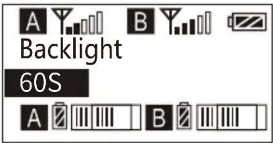
Backlight 60S8.2 Long press SET button to enter 'Backlight Mode' display page
text_image
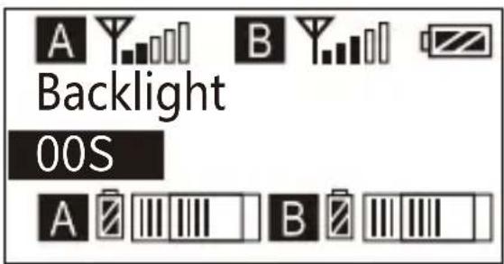
Backlight 60S8.3 Short press ◀ button to adjust the backlight lighting time or you can turn it off for power saving
text_image
A Y Backlight 00S A B8.4 Short press SET button to confirm
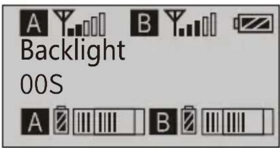
text_image
Backlight 00S9. System Language
9.1 Short press ◀ ▶ button to 'Language' display page
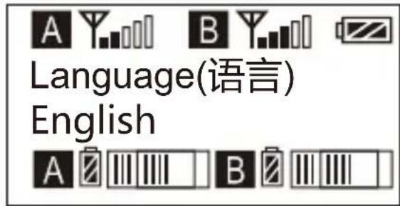
text_image
Language(语言) English9.2 Long press SET button to enter 'Language' display page
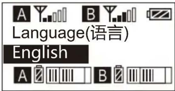
text_image
A Y B Y Language(语言) English A B9.3 Short press ◀ button to select language
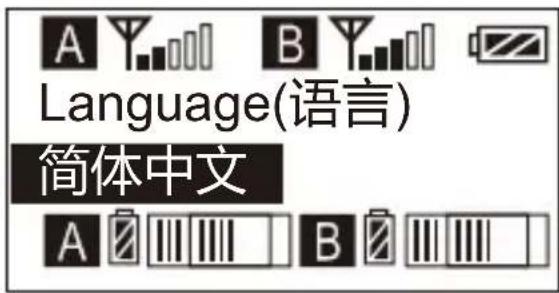
text_image
A Y B Y Language(语言) 简体中文 A B B9.4 Short press SET button to confirm
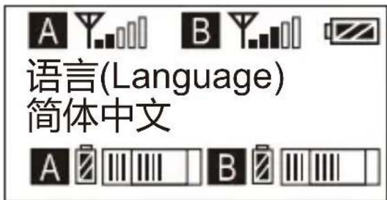
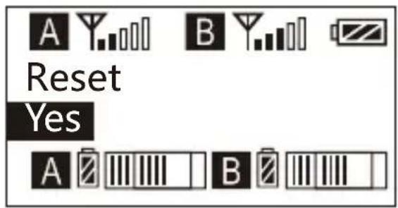
10.3 Short press ◀ button to select whether to restore factory Setting
text_image
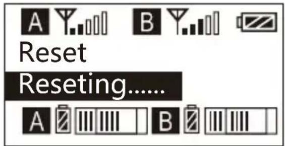
A Y B Y Reset Yes A Z III III I B Z III III10.4 Short press SET button to confirm and restore factory setting
text_image
Reset Reseting...... A B11. Version
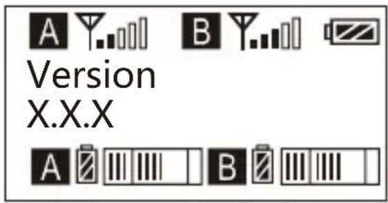
11.1 Press ◀ button to 'Version' display page to check the version
text_image
A Y. B Y. Version X.X.X A BSpecification
Lavalier Transmitter TX
| Signal / Noise | >65dB |
| Antenna | 1/4 Wavelength Wire Antenna |
| Stray Radiation | <-60dBc |
| Sound Delay | <20ms |
| Audio Distortion | <0.5% |
| Battery | AA Batteries x 2pcs |
| Dimension | 84 x 63.5 x 23mm |
| Operating Temperature | 0°C ~ 50°C |
| Storage Temperature | -20°C ~ 60°C |
Hand-held Transmitter HTX
| Signal / Noise | >65dB |
| Antenna | PCB Antenna |
| Stray Radiation | <-60dBc |
| Sound Delay | <20ms |
| Audio Distortion | <0.5% |
| Battery | AA Batteries x 2pcs |
| Dimension | Φ53.5(MAX) x 253mm |
| Operating Temperature | 0°C ~ 50°C |
| Storage Temperature | -20°C ~ 60°C |
Receiver RX
| Signal / Noise | >65dB |
| Antenna | 1/4 Wavelength Wire Antenna |
| Receiving Sensitivity | <-93dBm |
| Stray Radiation | <-60dBc |
| Sound Delay | <20ms |
| Audio Distortion | <0.5% |
| Battery | AA Batteries x 2pcs |
| Dimension | 84 x 63.5 x 23mm |
| Operating Temperature | 0°C ~ 50°C |
| Storage Temperature | -20 °C ~ 60 °C |
CVM-WM200
UHF无线麦克风
natural_image
Three black COMICA WMOXX transmitters with attached antennas, displayed against a white background (no visible text or symbols on devices)用户使用手册
前言
natural_image
Line drawing of a walkie-talkie device with antenna and control panel (no text or symbols)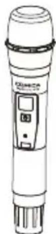
natural_image
Line drawing of a handheld electronic device with a control panel (no text or symbols)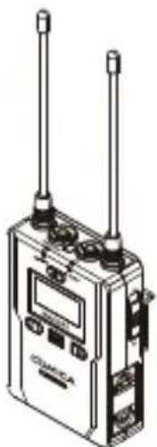
natural_image
Illustration of a walkie-talkie device with two speakers and control knobs (no text or symbols visible)natural_image
Two identical walkiehones with one plus another, no text or symbols presentTX RX
natural_image
Close-up of a black cord with two earphones and a connector (no text or symbols visible)1
natural_image
Abstract black line drawing on white background (no text or symbols)②
natural_image
Close-up of a black cable with two connectors, no visible text or symbols③
4

natural_image
Simple line drawing of two abstract geometric shapes (no text or symbols)⑤
natural_image
Black plastic mechanical component with a circular feature and rectangular base (no visible text or symbols)⑥

⑦
8
9
⑩

每一个搭配的配件包括:
$$ \mathrm{WM200(A)} = \textcircled {1} \mathrm{x2} + \textcircled {2} + \textcircled {3} + \textcircled {4} + \textcircled {5} \mathrm{x3} + \textcircled {6} + \textcircled {7} \mathrm{x2} + \textcircled {8} + \textcircled {9} + \textcircled {1 0} $$
$$ \mathrm{WM200(C)} = \textcircled {1} + \textcircled {2} 3 + 4 6 + \bigcirc + 5 7 8 9 + \bigcirc + \bigcirc + \bigcirc + \bigcirc + \bigcirc + 1 0 $$
部件介绍及说明
部件说明
领夹发射器
text_image
Labeled diagram of a Comica TV station with numbered components and control buttons手持发射器
text_image
DMICA LCF High LOM RF ⑤ ⑥ ③ ④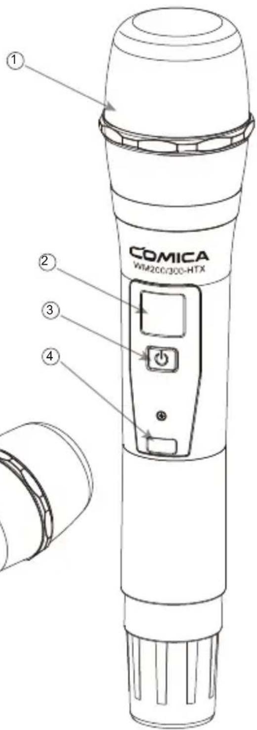
text_image
① COMICA WiM200/300-HTX ② ③ ④接收器
natural_image
Technical line drawing of a device with labeled ports and a central screen (no readable text or symbols)natural_image
Illustration of a computer tower connected to a microphone and sound waves (no text or symbols)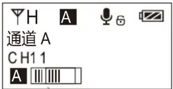
natural_image
Person wearing white shorts holding hands with a handheld electronic device (no visible text or symbols)- 与接收器进行频道匹配成功后,即可使用

频道匹配请见屏幕操作部分
手持发射器
- 将电池按照正负极指示装入发射器电池仓
natural_image
Diagram of a remote control panel with two buttons and an arrow pointing to the left side (no text or symbols)- 与接收器进行频道匹配成功后,即可使用

频道匹配请见屏幕操作部分
接收器
text_image
Diagram illustrating the assembly of a DMM-4 remote control device, showing signal transmission from antenna to camera.text_image
语言 (Language) English A8.4 短按 SET 按键确定
text_image
Language (语言) English9. 恢复出厂设置
text_image
低切开关 发射功率高/低切换 LCF High Low RF接收器
屏显说明
A通道信号强度
B通道信号强度 电量
A通道 B通道 A通道频道 B通道频道
text_image
OUTPUT AIR/PF AIR/PF WMO200-PX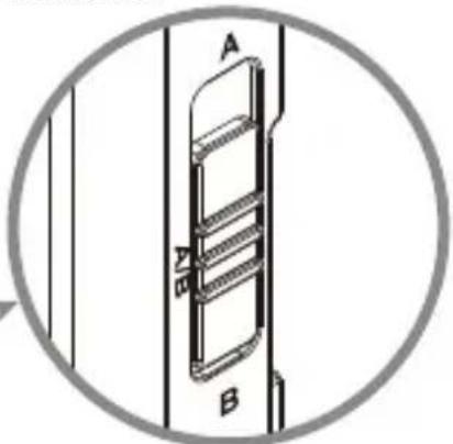
natural_image
Technical line drawing of a door or cabinet with labeled parts A and B, enclosed in a circular frame (no text or symbols beyond labels)A、B及A/B通道选择开关
text_image
QR code image containing encoded data, no visible human-readable textwww.comica-audio.com
The COMICA LOGO is trademark which is registered and owned by Comica Technology Co., Ltd
Email: support@comica-audio.com