SCG 6020X - Cooker SCHNEIDER - Free user manual and instructions
Find the device manual for free SCG 6020X SCHNEIDER in PDF.


| Product Type | Freestanding Gas Hob with Electric Oven Cooker |
| Brand | Schneider |
| Model | SCG 6020X |
| Width | 60 cm |
| Height | 85 cm |
| Depth | 60 cm |
| Weight | Approx. 50 kg |
| Power Supply | 220-240 V / 50-60 Hz for oven; Gas supply for hob |
| Oven Type | Electric conventional and fan-assisted |
| Hob Type | 4 gas burners including wok burner |
| Oven Functions | Convection, grill, defrost, fan cooking |
| Energy Efficiency Class | A |
| Cleaning Type | Standard enamel interior, easy-clean glass door |
| Safety Features | Flame failure safety device on gas burners, child lock, overheat protection |
| Spare Parts Availability | Available through Schneider service providers |
| Repair Index | 8.5 / 10 |
| Installation Type | Freestanding, requires gas connection and electrical outlet |
| Oven Capacity | Approx. 70 liters |
| Hob Ignition | Automatic ignition via spark plug |
| Warranty | 2 years manufacturer warranty |
Frequently Asked Questions - SCG 6020X SCHNEIDER
User questions about SCG 6020X SCHNEIDER
0 question about this device. Answer the ones you know or ask your own.
Ask a new question about this device
Download the instructions for your Cooker in PDF format for free! Find your manual SCG 6020X - SCHNEIDER and take your electronic device back in hand. On this page are published all the documents necessary for the use of your device. SCG 6020X by SCHNEIDER.
USER MANUAL SCG 6020X SCHNEIDER
Our objective is to make this product provide you with the best output which is manufactured in our modern facilities in a careful working environment, in compliance with total quality concept.
Therefore, we suggest you to read the user manual carefully before using the product and, keep it permanently at your disposal.
Note: This user manual is prepared for more than one model. Some of the features specified in the Manual may not be available in your appliance.
All our appliances are only for domestic use, not for commercial use.
"THISAPPLIANCESHALLBEINSTALLEDINACCORDANCEWITHTHE REGULA TIONS FORCE AND ONLY USED IN A WELL VENTILATED SPACE. READ THE INSTRUCTIONS BEFORE INSTALLING OR USING THIS APPLIANCE"
"Conforms with the EEE Regulations."
CONTENTS
Important warnings
Introduction of the Appliance 6
Important warnings
Chain Lashing Illustration 8
Installation of your oven 9
Technical features of your oven 9
If the appliance does not operate 11
Control panel 12
Using cooker section 12
Using oven section 14
Maintenance and cleaning 15
Installation of the Oven Door 16
Cleaning and maintenance of the
oven's front door glass 17
Changing the Oven Lamp 17
Accessories 18
Nozzle change operation 19
Reduced flame gas cock adjustment 19
Removal of the Lower and Upper Burner and
Installation of the Injector to the Gas Oven 20
IMPORTANT WARNINGS
-
Pay attention to minimum health and safety requirements.
-
The cooker is supplied setup according to the conditions shown on the rating label which is stuck to the rear of the appliance. From this sticker you can learn for which gas type (LPG or NG) this appliance is configured when supplied.
-
Keep the electrical cable of your oven away from the hot areas.
-
If the supply cord is damaged, it must be replaced by the manufacturer its services agent or similar qualified persons in order to avoid hazard.
-
Ensure that the appliance is switches off before replacing the lamp to avoid the possibility of electric shock.
-
In case of power failure, readjust your timer definitely. Otherwise, the oven will not operate (Digital Timer).
-
Your oven can be having different output pressure according to your countries gas and pressure specifications. Be sure that the cooker is configured correctly for local requirements (for example, the jets must be suitable for local gas type and gas pressure).
-
Connect your oven to LPG in shortest way and without any leakage. Min. 40 cm Max. 125 cm.
-
When making gas leakage check, never use any flame type like those of lighter, matches, cigarette fire or similar ones.
-
Usage of your appliance creates moisture and heath in the room it is placed, make sure that your kitchen is ventilated well. Maintain the natural ventilation ducts properly.
11.CAUTION! Do not touch hot parts with bare hands and keep children well supervised
-
When the oven is hot never touch the oven glass by hand.
-
Before starting to use your appliance, keep curtain, tulle, paper or inflammable things away from your appliance. Do not keep combustible or inflammable things in or on the appliance.
-
This appliance is for cooking purposes only. It must not be used for other purposes, for example room heating. All our appliances are only for domestic use, not for commercial use.
- For disconnection from the supply mains having a contact separation in all poles that provide full disconnection, must be incorporated in fixed wiring in accordance with the wiring rules.
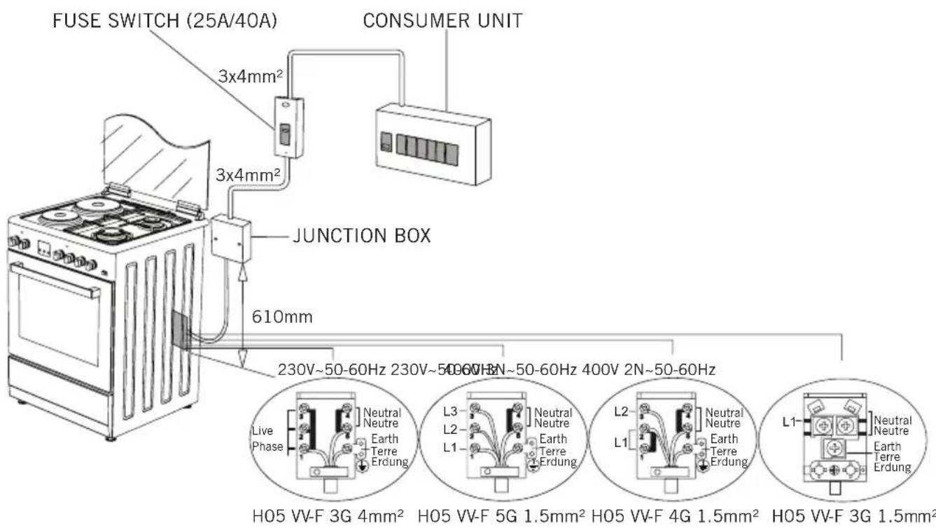
- Some models are supplied without a plug-an-lead set. In this case please use a flexible cable to suitable for connection to mono phase: H05 VV-F3G4mm 2 or for 3 phase: H05 VV-F 5G 1.5mm 2
- This appliance is produced in accordance with the safety regulations. Incorrect use will harm people and appliance.
- Children should be supervised to ensure that they do not play with the appliance. Never let them play with the appliance.
- Unattended cooking on a hob with fat or oil can be dangerous and may result in fire. NEVER try to extinguish a fire with water, but switch off the appliance and then cover flame e.g. with a lid or a fire blanket.
- Danger of fire: do not store items on the cooking surfaces
- This appliance is not intended for use by persons (including children) with reduced physical, sensory and mental capabilities or lack of experience and knowledge, unless they have been given supervision or instruction concerning the use of the appliance by a person responsible for their safety.
- "CAUTION: Accessible parts may be hot when the grill is in use. Young children should be kept away"
INTRODUCTION OF THE APPLIANCE
text_image
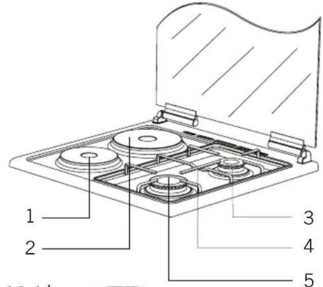
1 2 3 4 5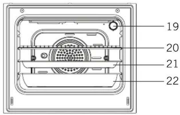
text_image
19 20 21 22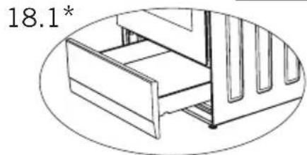
natural_image
Technical line drawing of a mechanical assembly with no visible text or symbols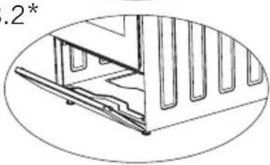
natural_image
Technical line drawing of a mechanical assembly with no visible text or symbolsFigure 18.1 and 18.2 are optional for ovens with dimensions 50x60 and 60x60(*)
Figure 18.1 is not available for oven with dimension 50x55 and 18.2 is optional. (*)
text_image
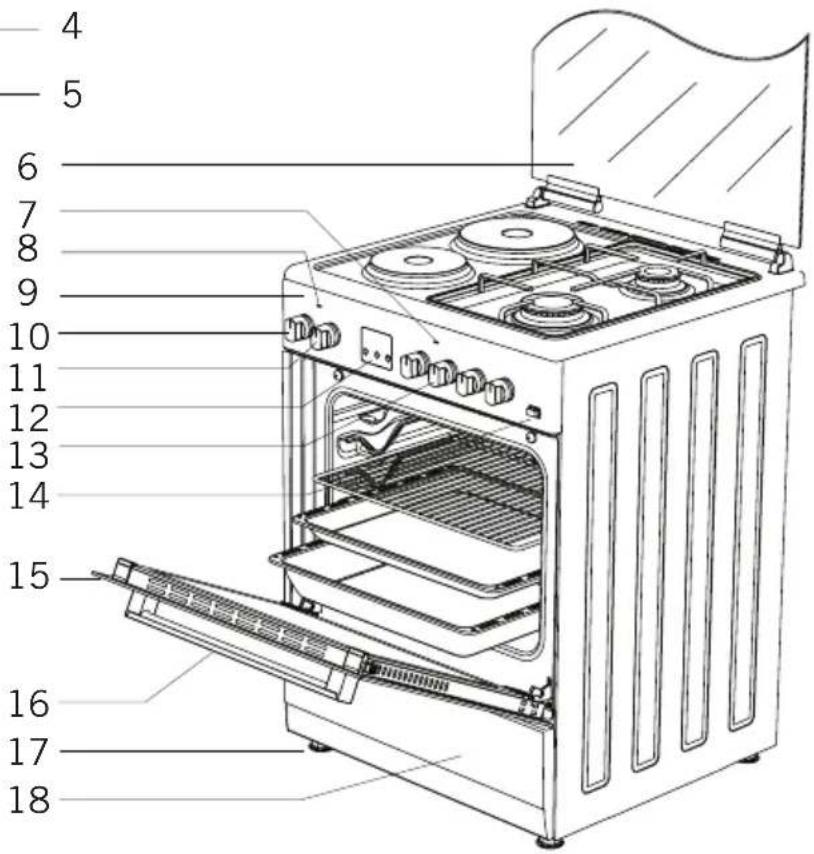
Labeled diagram of a 18-pin oven with numbered parts for identification- Hotplate ∅145mm
- Hotplate ∅185mm
- Middle Burner
- Trivet
- Large Burner
- Glass Door (Sheet Metal Door)
- Cooker Section Led Lamp
-
Oven Section Led Lamp
-
Control Panel
- Thermostat Setting
- Oven Setting
- Digital Timer
- Cooker Section Control Switches
- Push Button Lighter
- Door
-
Handle
-
Plastic Leg
- Lower Cabinet
Door
18.1 Drawer
18.2 Flap Door - Lamp
- Grill
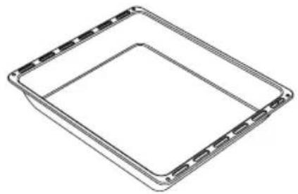
- Standard Tray
- Deep Tray
IMPORTANT WARNINGS
Electrical Connection and Security
- Your oven requires 16 or 32 Ampere fuse according to the appliance's power. If necessary, installation by a qualified electrician is recommended.
- Your oven is adjusted in compliance with 230V\~50-60Hz. (or-230V/400V\~50-60Hz.) electric supply. If the mains are different from this specified value, contact your authorized service.
- Electrical connection of the oven should only be made by the sockets with earth system installed in compliance with the regulations. If there is no proper socket with earth system in the place where the oven will be placed, immediately contact a qualified electrician. Manufacturer shall never be responsible from the damages that will arise because of the sockets connected to the appliance with no earth system. If the ends of the electrical connection cable are open, according to the appliance type, make a proper switch installed in the mains by which all ends can be disconnected in case of connecting / disconnecting from / to the mains.
- If your electric supply cable gets defective, it should definitely be replaced by the authorized service or qualified electricians in order to avoid from the dangers.
- Electrical cable should not touch the hot parts of the appliance.
- Please operate your oven in dry atmosphere.
Gas Connection and Security
Please operate your oven in dry atmosphere.
-
Fit the clamp to the hose. Push one of the hose until it goes to the end of the pipe.
-
For the sealing control; ensure that the buttons in the control panel are closed, but the gas cylinder is open. Apply some soap bubbles to the-connection. If there is gas leakage, there will be foaming in the soaped area.
-
The oven should be using a well ventilation place and should be install on flat ground.
-
Re-inspect the gas connection.
-
When placing your oven to its location, ensure that it is at the counter level. Bring it to the counter level by adjusting the feet if necessary.
-
Do not make gas hose and electrical cable of your oven go through the heated areas, especially through the rear side of the oven. Do not move gas connected oven. Since the forcing shall loosen the hose, gas leakage may occur.
-
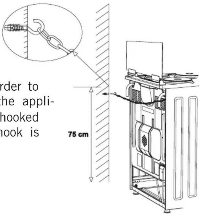
Before using the appliance, in order to ensure safe use, be sure to
GB
fix the appliance to the wall using the chain and hooked screw supplied. Ensure that the hook is screwed into the wall securely.
- Please use flexible hose for gas connection.
text_image
FUSE SWITCH (25A/40A) CONSUMER UNIT 3x4mm² 3x4mm² JUNCTION BOX 610mm 230V~50-60Hz 230V~50-60Hz 400V 2N~50-60Hz Live Phase Neutral Neutre Earth Terre Erdung L3 L2 L1 Neutral Neutre Earth Terre Erdung L2 L1 Neutral Neutre Earth Terre Erdung H05 VV-F 3G 4mm² H05 VV-F 5G 1.5mm² H05 VV-F 4G 1.5mm² H05 VV-F 3G 1.5mm²Chain Lashing Illustration
Before using the appliance, in order to ensure safe use, be sure to fix the appliance to the wall using thechain and hooked screw supplied. Ensure that the hook is screwed into the wall securely.
text_image
order to he appli- hooked hook is 75 cmINSTALLATION OF YOUR OVEN
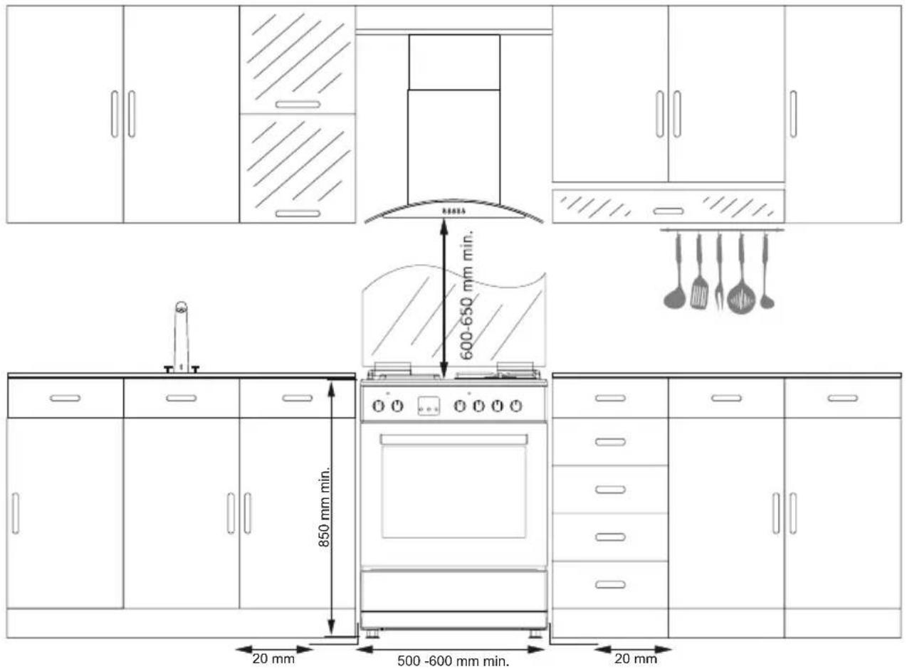
text_image
600-650 mm min. 850 mm min. 20 mm 500 -600 mm min. 20 mm| TECHNICAL FEATURES OF YOUR OVEN | |||
| SPECIFICATIONS 50x55 50x60 60x60 | |||
| Outer width 500mm 500mm | 600mm | ||
| Outer depth 565mm 630mm | 630mm | ||
| Outer height 855mm 855mm | 855mm | ||
| Inner width 341mm 341mm | 441mm | ||
| Inner depth 443mm 443mm | 443mm | ||
| Inner height 316mm 316mm | 316mm | ||
| Inner volume 48lt 48lt 62lt | |||
| Lamp power 15W 15W 15W | |||
| Bottom heating element 1000W 1000W 1200W | |||
| Top heating element | 800W 800W | 1000W | |
| Turbo heating element | ---- | 1800W 2200W | |
| Grill heating element | 1500W 1500W | 2000W | |
GB
| Supply Voltage | 220V-240V AC,50-60Hz (Or 230V400V AC,50-60 Hz) |
| Hot Plate 145 mm 1000 W | |
| Hot Plate 180 mm 1500 W | |
| Hot Plate rapid 145 mm 1500 W | |
| Hot Plate rapid 180 mm 2000 W |
| BURNER INJECTOR VALUES ACCORDING TO THE GAS TYPE | LPG G30/28-30 mbar | NG G20/20 mbar | NG G25/25 mbar | |
| Wok Burner | Injector ∅ mm | 0,96 1,30 1,40 | ||
| Power kW 3,60 | 3,35 3,66 | |||
| Consumption Gr/h,m3/h | 259,20 0,30 | 0 0,365 | ||
| Rapid Burner | Injector ∅ mm | 0,85 1,15 1,15 | ||
| Power kW 2,75 | 2,75 2,75 | |||
| Consumption Gr/h,m3/h | 198 0,263 | 0,287 | ||
| Semi Rapid Burner | Injector ∅ mm | 0,65 0,97 0,97 | ||
| Power kW 1,60 | 1,70 1,70 | |||
| Consumption Gr/h,m3/h | 115,20 0,16 | 5 0,175 | ||
| Auxiliary Burner | Injector ∅ mm | 0,50 0,72 0,72 | ||
| Power kW 0,90 | 0,90 0,90 | |||
| Consumption Gr/h,m3/h | 64,80 0,08 | 6 0,097 | ||
| Oven Burner | Injector ∅ mm | 0,65 0,97 0,97 | ||
| Power kW 1,80 | 1,85 1,85 | |||
| Consumption Gr/h,m3/h | 129,60 0,17 | 4 0,192 | ||
| Grill Burner | Injector ∅ mm | 0,60 0,92 0,92 | ||
| Power kW 1,50 | 1,55 1,55 | |||
| Consumption Gr/h,m3/h | 108 0,153 | 0,164 | ||
IF THE APPLIANCE DOES NOT OPERATE
- Please check the plug of power supply cord has a well connection with wall socket or not.
- Please check the electric network.
- Please check the fuse.
- Please check power supply cord for any damage problems.
- If you can not solve the problem, get in contact with manufacturer supplier service agent or similar qualified persons.
DESCRIPTION OF OVEN and CONTROL PANELS
 | Tumspit Fan | ||
 | Top + Bottom heating element | Turbo heating + Fan | |
 | Lamp | Bottom + Top heating elements + Fan | |
 | Bottom heating element + Fan | Grill heating element+Fan | |
 | Grill heating element | Grill burner / Grill heating element | |
 | Grill heating element+Lamp | Top heating element | |
 | Electrical timer | Oven burner / Bottom heating element | |
 | Flame Ignition lighter |
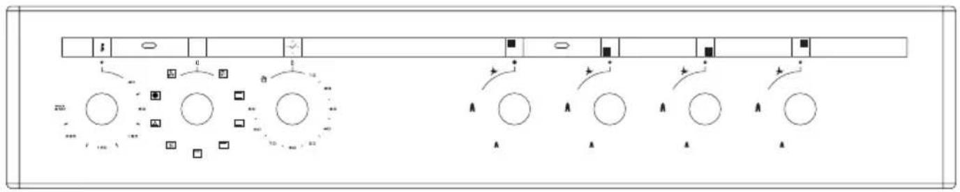
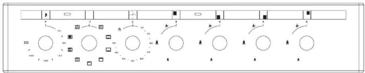
THERMOSTAT KNOB; In order to operate the oven, thermostat must be-adjusted to desired temperature. Your thermostat has a feature of adjustment to 50 - 280 degree.
MECHANIC TIMER KNOB(Optional); Inordertooperatetheoven, timerswitch should be adjusted to desired time from 0-90 minute. You can use cooking time table.
CONTROL PANELS
flowchart
graph TD
    A["Start"] --> B{Decision}
    B -->|Yes| C["Process Step 1"]
    B -->|No| D["Process Step 2"]
    C --> E["End"]
    D --> F["End"]
flowchart
graph TD
    A["Start"] --> B{Decision}
    B -->|Yes| C["Process Step 1"]
    B -->|No| D["Process Step 2"]
    C --> E["End"]
    D --> F["End"]
 |  |  |  |
| Front electric hot plate | Rear electric hot plate | Rear left burner (middle burner) | Front left burner (big burner) |
| Grill burner or heating element | Oven burner (optional) or heating element | Timer (optional) | Thermostat (optional) |
| Front electric hot plate | Rear electric hot plate | Rear left burner (middle burner) | Front left burner (big burner) |
 |  |  |  |
| Grill burner or heating element | Oven burner (optional) or heating element | Timer (optional) | Thermostat (optional) |
USING COOKER SECTION
Using Gas Burners:
| WOK Burner 24-28cm |
| Big Burner 22-26cm |
| Normal Burner 18-22cm |
| Small Burner 12-18cm |
- Closed
Fully open
Half open
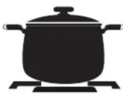
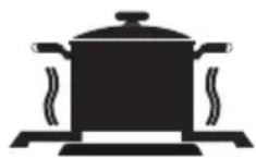
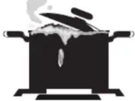
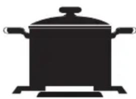
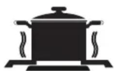
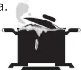
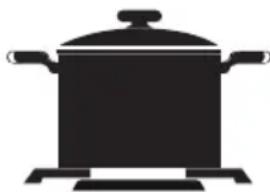
- In order to obtain maximum output, be careful that the saucepar which will be used should be flat bottomed, and use the saucepans with dimensions given herein above.
- The valves controlling the gas cookers have special security mechanism. In order to light the cooker always press on the switch forward and bring it to flame symbol by turnin counterclockwise. All of the lighters shall operate and the cooker you controlled shall light only. Keep the switch pressed until ignition i performed. Press on the lighter button and
turn the knob counter clockwise.
- Do not continuously operate the igniter for more than 15 seconds. If the burner does not ignite, wait minimum one minute before try again. If the burner is extinguished because of any reason, close the gas control valve and wait minimum one minute before try again.
- In models with Gas Security System, when flame of the cooker is extinguished, control valve cuts off the gas automatically. For operate the burners with gas security system you must press the knob and turn counter-clock-wise. After the ignition you must wait nearly 5-10 second for gas security systems activation. If the burner is extinguished for of the any reason, close the gas control valve and wait a minimum of one minute before trying again.
Using Hot Plates
| LEVEL 1 | LEVEL 2 | LEVEL 3 | LEVEL 4 | LEVEL 5 | LEVEL 6 | ||
| 80 mm | 200 W | 250 W | 450 W | --- --- --- | |||
| 145 mm | 250 W | 750 W | 1000 W | --- --- | |||
| 180 mm | 500 W | 750 W | 1500 W | --- --- | |||
| 145 mm rapid | 500 W | 1000 W | 1500 W | --- --- --- | |||
| 180 mm rapid | 850 W | 1150 W | 2000 W | --- --- --- | |||
| 145 mm | 95 W | 155 W | 250 W | 400 W | 750 W | 1000 W | |
| 180 mm | 115 W | 175 W | 250 W | 600 W | 850 W | 1500 W | |
| 145 mm rapid | 135 W | 165 W | 250 W | 500 W | 750 W | 1500 W | |
| 180 mm rapid | 175 W | 220 W | 300 W | 850 W | 1150 W | 2000 W |
- Electric hotplates have standard of 6 temperature levels (as describe herein above)
- When using first time, operate your electric hotplate in position 6 for 5 minutes. This will make the agent on your hotplate which is sensitive to heat get hardened by burning.
- Use flat bottomed saucepans which fully contact with the heat as much as you can, so that you can use the energy more productively.
natural_image
Silhouette of a cooking pot on a gas stove (no text or symbols)False
False
natural_image
Simple black-and-white illustration of a cooking pot with steam rising from it (no text or symbols)False
natural_image
Silhouette of a cooking pot with lid and side handles (no text or symbols)True
GB
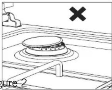
Before operating your hob please make sure that the burner caps are well positioned. The right placement of the burner caps are shown as below.
natural_image
Diagram of a kitchen appliance with a valve and switch, labeled Figure 2 (no text or symbols on the diagram itself)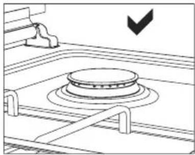
natural_image
Line drawing of a gas stove with a circular vent and cooling fins (no text or symbols)Figure 1 Figure 2
USING OVEN SECTION
Using oven burners
-
If your oven equipped with burners that operates with gas, appropriate knob should be used in order to ignite the burners. Some models have automatic ignition from the knob; it is easy to ignite the burner by turning the knob. Also, burners can be ignited by pressing the ignition button or they can be ignited with a match.
-
Do not continuously operate the igniter for more than 15 seconds. If the burner does not ignite, wait minimum one minute before trying again. If the burner is extinguished for of the any reason, close the gas control valve and wait a minimum of one minute before trying again.
Using oven heating elements
- When your oven is operated first time, an odor will be spread out which will be sourced from using the heating elements. In order to get rid of this, operate it at 250 °C for 45-60 minutes while it is empty.
- Oven control knob should be positioned to desired value; otherwise oven does not operate.
- Kinds of meals, cooking times and thermostat positions are given in cooking table. The values given in the cooking table are characteristic values and were obtained as a result of the tests performed in our laboratory. You can find different flavors suitable for your taste depending on your cooking and using habits.
- You can make chicken revolving in your own by means of the accessories.
- Cooking times: The results may change according to the area voltage and material having different quality, amount and temperatures.
- During the time when cooking is being performed in the oven, the lid of the oven should not be opened frequently. Otherwise circulation of the heat may be imbalanced and the results may change.
- Using cake forms while cooking cake gives better result.
- 5 - 10 min. preliminary heating should be done prior cooking.
Cooking Time Table
| Meals Temperature (°C) Rack position Cooking time (min.) | |||
| Creamed cake 150-1 | 70 2 30-35 | ||
| Pastry 200-220 2 35-45 | |||
| Biscuit 160-170 3 20-25 | |||
| Cookie 160-170 3 20-35 | |||
| Cake 160-180 2 25-35 | |||
| Braided cookie 200- | 220 2 30-40 | ||
| Filo Pastry 180-220 | 2 35-45 | ||
| Savory pastry 160-180 2 20-30 | |||
| Lamb meat 210-230 | 1 90-120 | ||
| Veal | 210-230 1 90-120 | ||
| Mutton | 210-230 1 90-120 | ||
| Chicken (pieced) | 210-230 1 75-100 | ||
| Fish | 190-210 2 40-50 | ||
MAINTENANCE and CLEANING
- Disconnect the plug supplying electricity for the oven from the socket.
- While oven is operating or shortly after it starts operating, it is extremely hot. You must avoid touching from heating elements.
- Never clean the interior part, panel, lid, trays and all other parts of the oven by the tools like hard brush, cleaning mesh or knife. Do not use abrasive, scratching agents and detergents.
- After cleaning the interior parts of the oven with a soapy cloth, rinse it and then dry thoroughly with a soft cloth.
- Clean the glass surfaces with special glass cleaning agents.
- Do not clean your oven with steam cleaners.
- Before opening the upper lid of the oven, clean spilled liquid off the lid. Also, before closing the lid, ensure that the cooker table is cooled enough.
- Never use inflammable agents like acid, thinner and gasoline when cleaning your oven.
- Do not wash any part of your oven in dishwasher.
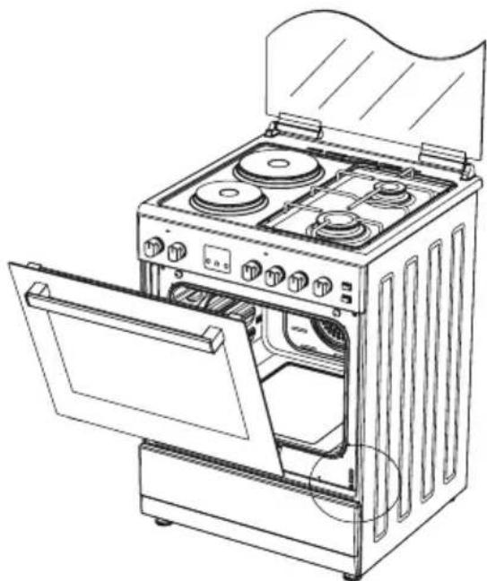
- In order to clean the front glass lid of the oven; remove the fixing
screws fixing the handle by means of a screwdriver and remove the oven door. Than clean and rinse it thoroughly. After drying, place the oven glass properly and re-install the handle.
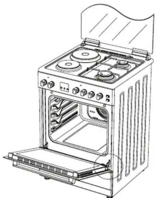
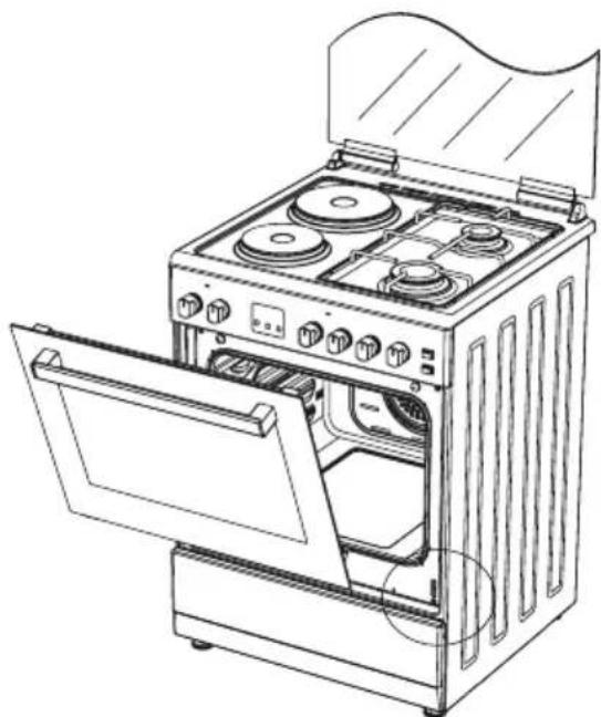
INSTALLATION OF THE OVEN DOOR
natural_image
Line drawing of an open oven with three stoves and a door, showing internal components (no text or symbols)Figure 3
natural_image
Line drawing of an open oven with four stovels and a door open, showing internal components (no text or symbols)Figure 4
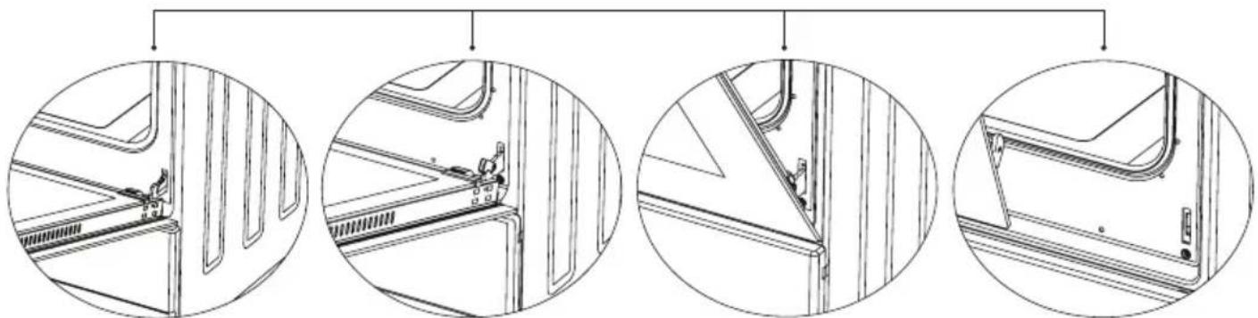
natural_image
Four circular diagrams showing internal structural components of a vehicle frame, with no visible text or symbols.Figure 3.1 Figure 3.2 Figure 4.1 Figure 4.2
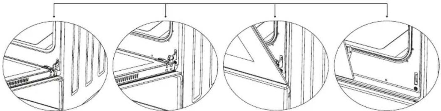
Completely open the oven door by pulling it to yourself. Afterwards, perform the un-locking process by pulling the hinge lock upwards with the help of a screw driver as shown in
Figure 3.1.
Bring the hinge lock to the widest angle as shown in Figure 3.2. Bring both hinges connecting the oven door to the oven to the same position.
Afterwards, close the oven door as to lean on the hinge lock as shown in Figure 4.1.
To remove the oven door, pull it upwards by holding it with both hands when close to the closed position as shown in Figure 4.2.
In order to re-place the oven door, perform the abovementioned steps in reverse.
CLEANING AND MAINTENANCE OF THE OVEN'S FRONT DOOR GLASS
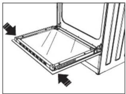
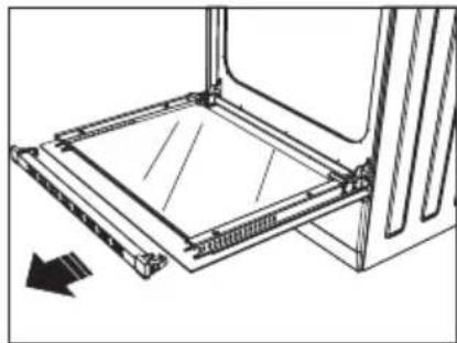
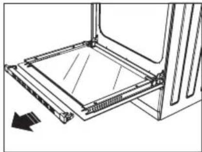
Remove the profile by pressing the plastic latches on both left and right sides as shown in Figure 5 and pulling the profile towards yourself a shown in Figure 6. Then remove the inner-glass as shown in Figure 7. If required, middle glass can be removed in the same way. After cleaning and maintenance are done, remount the glasses and the profile in reverse order.
Make sure the profile is properly seated in its place.
natural_image
Technical line drawing of a mechanical assembly with arrows indicating direction (no text or symbols)Figure-5 Figure-6
natural_image
Technical line drawing of a mechanical assembly with no visible text or symbols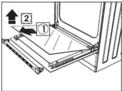
text_image
Diagram showing a mechanical assembly with labeled parts and directional arrows, including numbered annotations 1 and 2.Figure-7
CHANGING THE OVEN LAMP
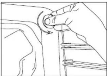
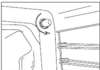
In order to avoid the possibility of an electric shock, ensure that the circuit of the appliance is open before changing the lamp. (The open-circuit is an electrical circuit that does not conduct current.)
1- First of all, cut the electrical connection of the appliance and ensure that the appliance is cooled down.
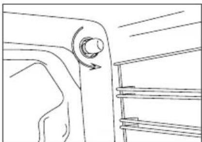
2- Remove the glass protection by turning as shown in the figure. If you have difficulty in turning it, the use of plastic gloves will help you.
3- Afterwards, remove the lamp by turning and install the new lamp with the same specifications. The specifications of the lamp should be as follows:
- 230 V, AC
- 15 W
- Type E14
4- Place the glass protection and complete the replacing process by plugging in the electric cable of the appliance. Now, you can use your oven.
natural_image
Line drawing of a hand adjusting a curved mechanical component (no text or symbols)Figure-8
natural_image
Line drawing of a vehicle's side profile showing the wheel and dashboard (no text or symbols)Figure-9
ACCESORIES
natural_image
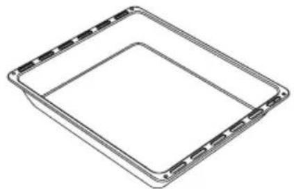
Pure geometric diagram of a square frame with no text, numbers, or symbolsDeep Tray
Used for pastries, deep fried foods and stew recipes. In case of frying directly on the grill for cakes, frozen foods and meat dishes, it can be used of oil pick-up tray.
natural_image
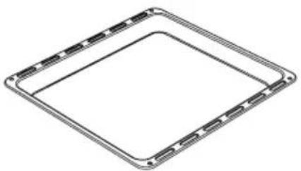
Pure geometric diagram of a square frame with rounded corners and internal lines, no text or symbols present.Tray
Used for pastries (cookies, biscuits etc.) and frozen foods.
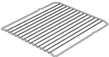
natural_image
Line drawing of a rectangular grid pattern with parallel lines (no text or symbols)Wire Grill
Used for frying and/or placing the foods to be baked, fried and frozen foods on the desired rack.
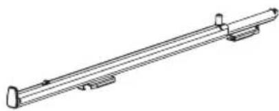
natural_image
Technical line drawing of a mechanical support or rod assembly (no text or symbols)Telescopic Rail
With the help of telescopic rails, the trays and/or wire racks can be easily placed and removed.
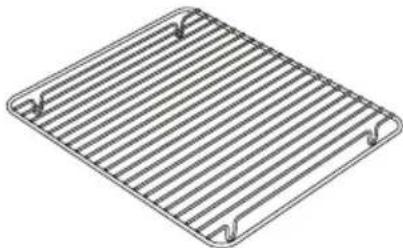
natural_image
Isometric view of a rectangular metal grate with slats and two side handles (no text or symbols)In Tray Wire Grill
Foods that can stick while cooking such as beef are placed on in tray grill. Thus, the contact and sticking of the food is prevented.
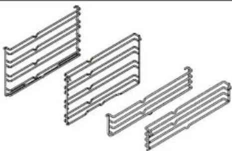
natural_image
Pure technical line drawing of four identical mechanical brackets without any text or symbolsLower and Upper Wire Racks
While cooking, you can place the deep tray and tray on the lower and upper wire racks.
natural_image
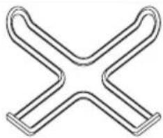
Pure geometric X-shaped line drawing without any text, numbers, or symbolsCoffee Pot Support Unit
Can be used for coffee pot.
GB
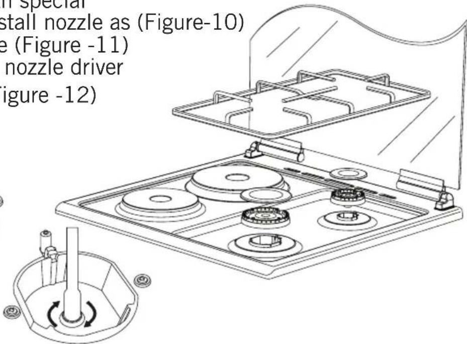
- Please use driver with special head for removed and install nozzle as (Figure-10)
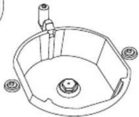
- Please remove nozzle (Figure -11) from burner with special nozzle driver and install new nozzle (Figure -12)
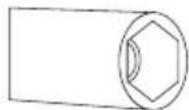
Figure-10
natural_image
Technical line drawing of a mechanical component with no visible text or symbolsFigure-11
text_image
in special install nozzle as (Figure-10) e (Figure -11) nozzle driver figure -12)Figure-12
Reduced Flame Gas Cock Adjustment:
| From LPG to NG From NG to LPG | |
| Rapid Burner 3 Turns Counterclockwise 3 Turns Clockwise | |
| Semi-Rapid Burner 2.5 Turns Counterclockwise 2.5 Turns Clockwise | |
| Auxiliary Burner 2 Turns Counterclockwise 2 Turns Clockwise | |
| WOK Burner 4 Turns Counterclockwise 4 Turns Clockwise | |
| Oven Burner 4,5 Turns Counterclockwise 4,5 Turns Clockwise | |
| Grill Burner 4 Turns Counterclockwise 4 Turns Clockwise |
natural_image
Line drawing of a hand inserting a button into a control panel (no text or symbols)Figure-13
natural_image
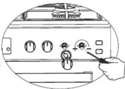
Line drawing of a hand pointing to a control panel with buttons and dials (no text or symbols)Figure-14
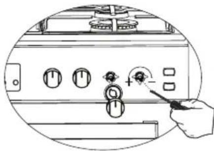
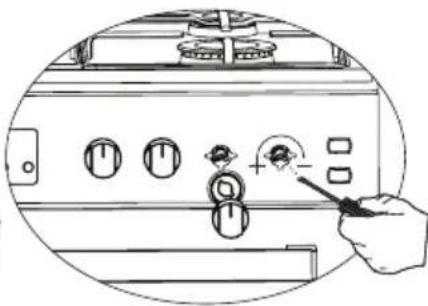
Remove the burner switches of the appliance as shown in Figure 13 and 14. In Figure 13, the setting mechanism is shown at the right lower corner of the tap and in Figure 14, just at the center of the tap. In order to re-place
the switches after making the appropriate adjustments in accordance with the above chart, apply the process reversely.
REMOVAL OF THE LOWER AND UPPER BURNER AND INSTALLATION OF THE INJECTOR TO THE GAS OVEN
Removal of the Upper Burner:
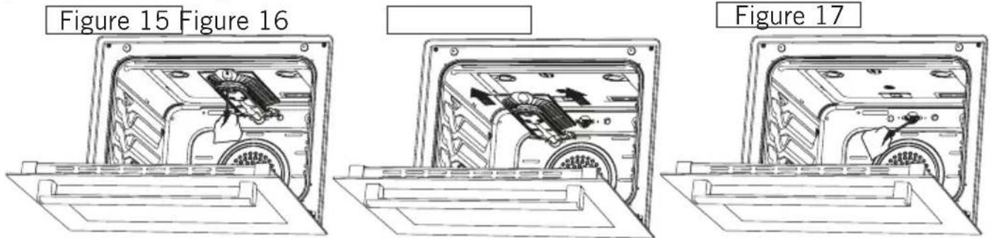
With the help of a screw driver, remove the screw as shown in Figure 15. As shown in Figure 16, remove the burner from its place by pulling it to yourself. As shown in Figure 17, remove the injector in the bearing with a socket wrench. In order to re-place the burner, apply the removal process reversely.
text_image
Figure 15 Figure 16 Figure 17Removal of the Lower Burner:
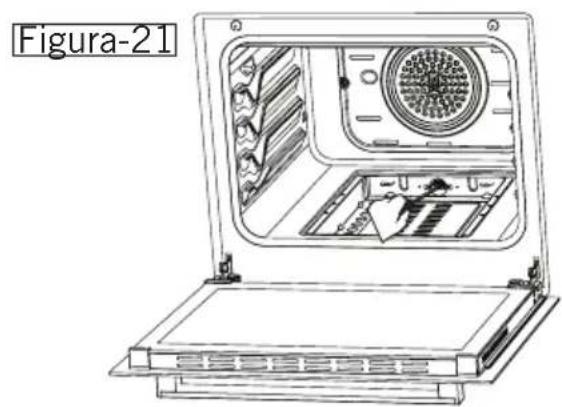
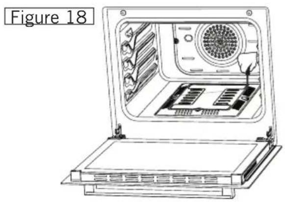
The lower burner door has been fixed with two screws. As shown in Figure 18, remove it with the help of a screw driver. Remove the door by pulling upwards as shown in Figure 19. Remove the burner from its place by pulling it to yourself as shown in Figure 20. As shown in Figure 21, remove the injector in the bearing with a socket wrench. In order to replace the burner, apply the removal process reversely.
natural_image
Line drawing of an open laptop with internal components and a labeled section 'Figure 18' (no text or symbols on the diagram itself)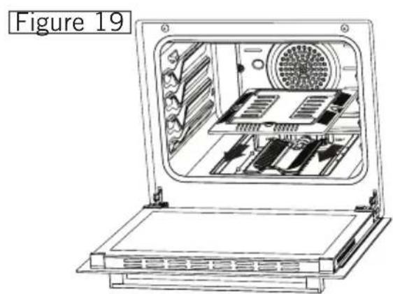
natural_image
Line drawing of an open refrigerator with internal compartments and ventilation slots (no text or symbols)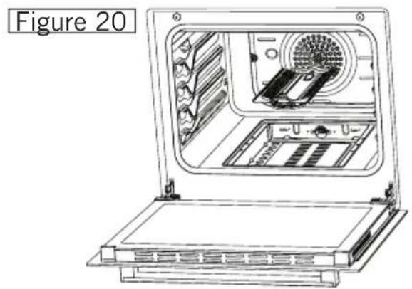
natural_image
Technical line drawing of an open laptop with internal components and ventilation slots (no text or symbols)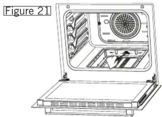
natural_image
Line drawing of an open laptop with internal components and ventilation slots (no text or symbols)natural_image
Technical line drawing of a mechanical component with internal channels and a circular outline (no text or symbols)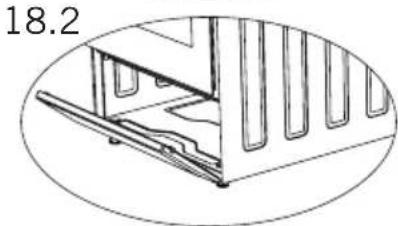
natural_image
Technical line drawing of a mechanical assembly with no visible text or symbols| LEVEL 1 LEVEL 2 LEVEL 3 LEVEL 4 LEVEL 5 LEVEL 6 | ||||||
| 80 mm | 200 W 250 W 450 W --- --- --- | |||||
| 145 mm | 250 W 750 W 1000 W --- --- --- | |||||
| 180 mm | 500 W 750 W 1500 W --- --- --- | |||||
| 145 mm rapid | 500 W 1000 W 1500 W --- --- --- | |||||
| 180 mm rapid | 850 W 1150 W 2000 W --- --- --- | |||||
| 145 mm | 95 W 155 W 250 W 400 W 750 W 1000 W | |||||
| 180 mm | 115 W 175 W 250 W 600 W 850 W 1500 W | |||||
| 145 mm rapid | 135 W 165 W 250 W 500 W 750 W 1500 W | |||||
| 180 mm rapid | 175 W 220 W 300 W 850 W 1150 W 2000 W | |||||
natural_image
Silhouette of a cooking pot on a portable stove (no text or symbols)False
False
natural_image
Silhouette of a cooking pot with steam rising from it, no text or symbols presentFalse
natural_image
Silhouette of a cooking pot on a stove (no text or symbols)True
natural_image
Line drawing of a vintage kitchen oven with multiple gas stove units and open door (no text or symbols)Figura 3
natural_image
Line drawing of an open oven with four stovels and a door open, showing internal components (no text or symbols)Figura 4
natural_image
Four circular diagrams showing mechanical assembly steps, including front and side views of a vehicle frame (no text or symbols present)Figura 3.1 Figura 3.2 Figura 4.1 Figura 4.2
natural_image
Technical line drawing of a mechanical assembly with arrows indicating direction (no text or symbols)Figura-5 Figura-6
natural_image
Technical line drawing of a mechanical assembly with no visible text or symbols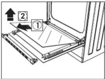
text_image
Diagram showing a mechanical assembly with labeled parts and directional arrows, including numbered annotations 1 and 2.Figura-7
natural_image
Line drawing of a hand adjusting a car seatbelt with a circular arrow indicating rotation (no text or symbols)Figura-8
natural_image
Line drawing of a mechanical component with a knob and arrow indicating rotation (no text or symbols)Figura-9
ACCESORIOS
natural_image
Pure technical line drawing of a square frame with mounting holes (no text or symbols)Bandeja Profunda
natural_image
Pure geometric diagram of a square frame with side tick marks, no text or symbols presentBandeja
natural_image
Line drawing of a rectangular grid pattern with parallel lines, no text or symbols presentParrilla de Alambre
natural_image
Technical line drawing of a long cylindrical mechanical component with mounting flanges (no text or symbols)Reil Telescópico
natural_image
Line drawing of a rectangular metal grate with slats and two side supports (no text or symbols)Parrilla de Alambre Dentro de Bandeja
natural_image
Pure technical line drawing of three identical mechanical components arranged in a zigzag pattern (no text or symbols)natural_image
Pure geometric X-shaped line drawing without any text, numbers, or symbolsCafetera
natural_image
Technical line drawing of a mechanical component with no visible text or symbolsFigura-11

natural_image
Line drawing of a gas stove with cooling fans and a tray (no text or symbols)
natural_image
Diagram of a mechanical device with rotating components and a central shaft (no text or symbols)Figura-12
natural_image
Line drawing of a hand pressing a button on a control panel with multiple switches (no text or symbols visible)Figura-13
natural_image
Line drawing of a hand pointing to a control panel with buttons and dials (no text or symbols)Figura-14
natural_image
Line drawing of an open oven with internal components and ventilation slots (no text or symbols)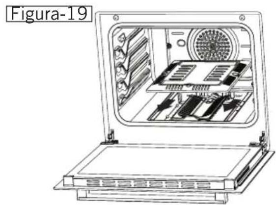
natural_image
Technical line drawing of an open laptop with internal components and ventilation slots (no text or symbols)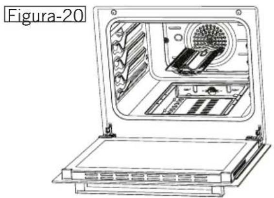
natural_image
Technical line drawing of an open industrial machine with internal components (no text or symbols)