
HmIP-SWO-PR - Humidifier Homematic IP - Free user manual and instructions
Find the device manual for free HmIP-SWO-PR Homematic IP in PDF.


User questions about HmIP-SWO-PR Homematic IP
0 question about this device. Answer the ones you know or ask your own.
Ask a new question about this device
Download the instructions for your Humidifier in PDF format for free! Find your manual HmIP-SWO-PR - Homematic IP and take your electronic device back in hand. On this page are published all the documents necessary for the use of your device. HmIP-SWO-PR by Homematic IP.
USER MANUAL HmIP-SWO-PR Homematic IP
natural_image
Illustration of a weather vane with an arrow, a bucket, and an insulator (no text or symbols)Lieferumfang
Anzahl Bezeichnung
Printed in Hong Kong
text_image
A B C D E F G H I2
text_image
homematic® System LED System Button J K L3

natural_image
Hand installing a System LED battery component into a cylindrical device (no text or symbols visible on the device itself)4
natural_image
Hand using a screwdriver to adjust internal components of a mechanical device (no visible text or symbols)Inhaltsverzeichnis
natural_image
Close-up of hands holding a metallic mechanical device with an arrow-shaped component extending from it (no text or symbols visible)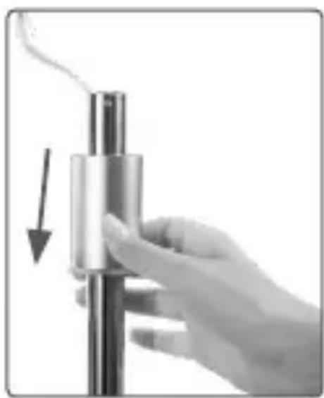
natural_image
Hand holding a metallic cylindrical object with a downward arrow indicating compression or dislocation (no text or symbols visible)natural_image
Close-up of hands assembling a mechanical device with an arrow and pointer (no text or symbols visible)natural_image
Close-up of a metallic weather vane with an arrowhead and pointed tip, mounted on a pole (no text or symbols visible)natural_image
Close-up of a hand using a tool to adjust or install a metallic mechanical component (no visible text or symbols)natural_image
Close-up of a conical lamp with a pointed tip and arrow indicator (no text or symbols)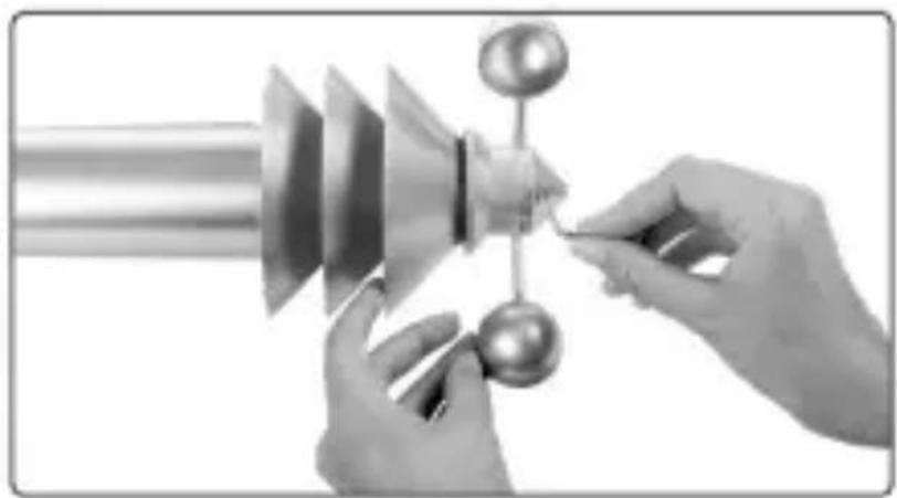
natural_image
Close-up of hands assembling a mechanical component with a metallic sphere and a vertical rod (no text or symbols visible)Schritt 3:
natural_image
Close-up of hands assembling a mechanical component, no visible text or symbolsnatural_image
Close-up of hands operating a stainless steel kitchen appliance with a handle, showing internal components and a directional arrow (no text or symbols)natural_image
Hand holding a metallic cylindrical object with a flared top, no visible text or symbols
natural_image
Close-up of a mechanical component with metallic parts and a curved shaft (no visible text or symbols)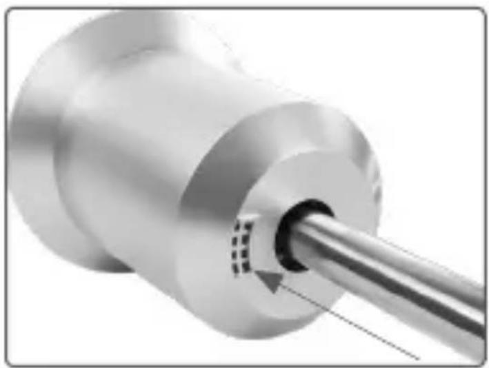
natural_image
Close-up of a metallic mechanical component with a cylindrical shaft and mounting hole (no visible text or symbols)Schritt 4:
natural_image
Close-up of a mechanical component with internal structure and cable (no visible text or symbols)natural_image
Cross-sectional view of a mechanical device with internal components and wiring (no visible text or symbols)natural_image
Hand holding a metallic funnel-shaped object with an arrow indicating direction (no text or symbols visible)
natural_image
Close-up of a mechanical component with metallic parts and a cylindrical shaft (no visible text or symbols)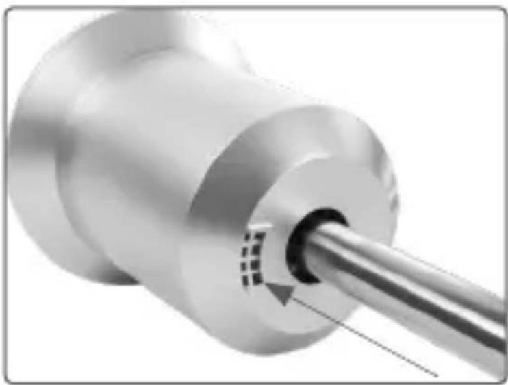
natural_image
Close-up of a metallic mechanical component with a cylindrical shaft and internal fastener (no text or symbols visible)1 Stainless steel mast
2 Screws
1 Screwdriver (hexalobular socket head)y
3 1.5 V LR6/mignon/AA batteries
1 User manual
Documentation © 2017 eQ-3 AG, Germany
All rights reserved. Translation from the original version in German. This manual may not be reproduced in any format, either in whole or in part, nor may it be duplicated or edited by electronic, mechanical or chemical means, without the written consent of the publisher.
Typographical and printing errors cannot be excluded. However, the information contained in this manual is reviewed on a regular basis and any necessary corrections will be implemented in the next edition. We accept no liability for technical or typographical errors or the consequences thereof.
All trademarks and industrial property rights are acknowledged.
Printed in Hong Kong
Changes may be made without prior notice as a result of technical advances.
151826 (web)
Version 1.4 (01/2019)
Table of contents
1 Information about this manual....43
2 Hazard information....43
3 Function and device overview 46
4 General system information 48
5 Mounting 48
6 First start-up....56
6.1 Teaching-in....56
6.2 Alignment of the weathervane 57
7 Replacing batteries 59
8 Troubleshooting 60
8.1 Weak batteries....60
8.2 Command not confirmed....61
8.3 Duty cycle 61
8.4 Error codes and flashing sequences 62
9 Restoring the factory settings 64
10 Maintenance and cleaning 65
10.1 General information....65
10.2 Cleaning the rain sensor 66
11 Information regarding the brightness sensor .....70
12 General information about radio operation....71
13 Technical specifications....72
1 Information about this manual
Please read this manual carefully before beginning operation with your Homematic IP component. Keep the manual so you can refer to it at a later date if you need to. If you hand over the device to other persons for use, please hand over this manual as well.
Symbols used:

Attention!
This indicates a hazard.
Please note:
This section contains important additional information.
2 Hazard information
Do not open the device (except the cover). It does not contain any parts that can be maintained by the user. If you have any doubts, have the device checked by an expert.
For safety and licensing reasons (CE), unauthorized change and/or modification of the device is not permitted.
The device is not a toy; do not allow children to play with it. Do not leave packaging material lying around. Plastic films/bags, pieces of polystyrene, etc. can be dangerous in the hands of a child.
We do not assume any liability for damage to property or personal injury caused by improper use or the failure to observe the hazard information. In such cases, any claim under warranty is extinguished! For consequential damages, we assume no liability!
Do not use the device if there are signs of damage to the housing or operating elements, for example, or if it demonstrates a malfunction. If you have any doubts, have the device checked by an expert.
Do operate the device only when its closed.
The device must be mounted in such a way that it cannot topple over, fall down or cause damage.
The supplied stainless steel mast (I) may only be used for mounting the weather sensor; under no circumstances may it be used for mounting any other objects (such as antennae or vanes, etc.).
Do not install the device so that it is the highest point in an outdoor area (e.g. on buildings, trees or masts). This creates a risk of lightning strikes. When installing the device on buildings, lightning protection regulations must be observed.

Select an installation site at which you can access the device for maintenance.

Using the device for any purpose other than that described in this operating manual does not fall within the scope of intended use and shall invalidate any warranty or liability.
3 Function and device overview
The Homematic IP Weather Sensor offers multiple application in outdoor areas for collecting weather data. The multifunctional sensor offers various application possibilities as it collects almost all relevant weather and climate information:
- temperature,
- humidity,
- wind direction,
- wind velocity,
- onset of rain,
- rainfall volume,
• brightness (relative) and
• duration of sunshine.
The data is cyclically transmitted by the weather sensor via radio communication to the Homematic IP app. Thus, you will always have the current values in sight or you can use the measured data information for controlling of other Homematic IP devices (e.g. moving shutters up in case of strong wind or extending awnings during sunshine).
Thanks to the wireless communication and battery operation, the weather sensor can be positioned anywhere and is easy to mount.
Device overview (see fig. 1):
(A) Collecting funnel of the rain sensor
(B) Rain sensor (rain detection, rainfall volume)
(C) Pipe 1
(D) Pipe 2
(E) Wind direction sensor
(F) Anemometer (wind velocity sensor)
(G) Main sensor (temperature, humidity, brightness)
(H) Pipe 3
(I) Stainless steel mast (in three parts)
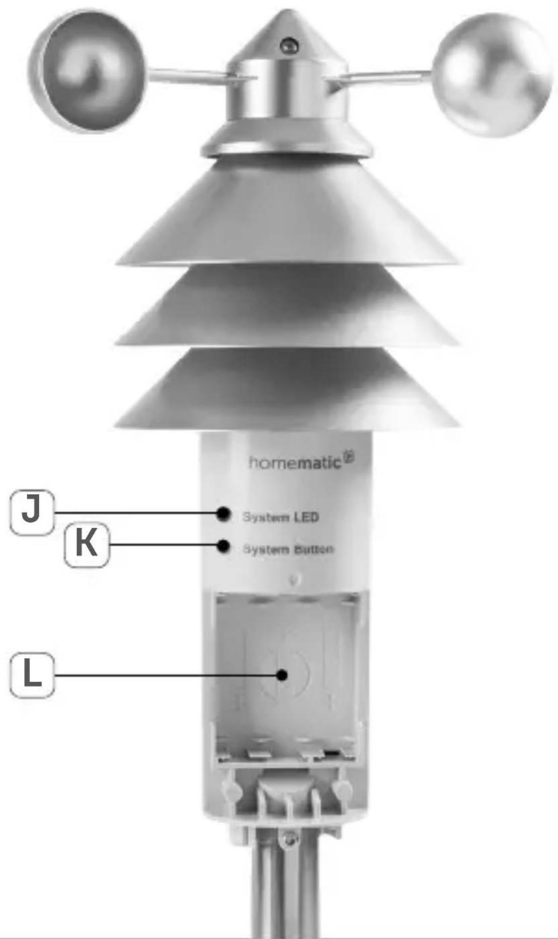
Overview main sensor (see fig. 2):
(J) System LED
(K) System button
(L) Battery compartment
4 General system information
This device is part of the Homematic IP smart home system and works with the Homematic IP radio protocol. All devices of the system can be configured comfortably and individually with the Homematic IP smartphone app. Alternatively, you can operate the Homematic IP devices via the Homematic Central Control Unit CCU2 or in connection with various partner solutions. The available functions provided by the system in combination with other components are described in the Homematic IP User Guide. All current technical documents and updates are provided at www.eQ-3.com.
5 Mounting
Before starting to set-up the device, you have to connect the single components of the weather sensor supplied. To do this, please proceed as follows:
Step 1:
- Remove the not yet completely assembled weather sensor and the wind direction sensor (E) from the packaging.
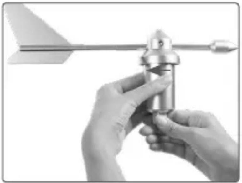
- Loosen the cover of the wind direction sensor by rotating it clockwise and slide the cover down onto pipe 2 (D).
natural_image
Close-up of hands holding a metallic mechanical component with an arrow pointer (no text or symbols visible)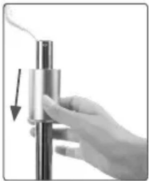
natural_image
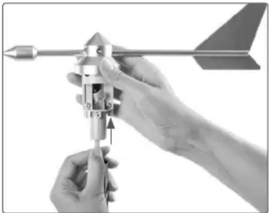
Hand holding a metallic cylindrical device with a downward arrow indicating force or motion (no text or symbols visible)- Lead up the cable that protrudes from pipe 2 through the lower opening of the wind direction sensor.
natural_image
Close-up of hands assembling a mechanical device with an arrow and pointer (no text or symbols visible)- Insert the wind direction sensor into pipe 2 and turn it so that the screw hole of the wind direc-
tion sensor is positioned above the bore hole of the pipe.
- Insert the cable plug into the corresponding socket.
natural_image
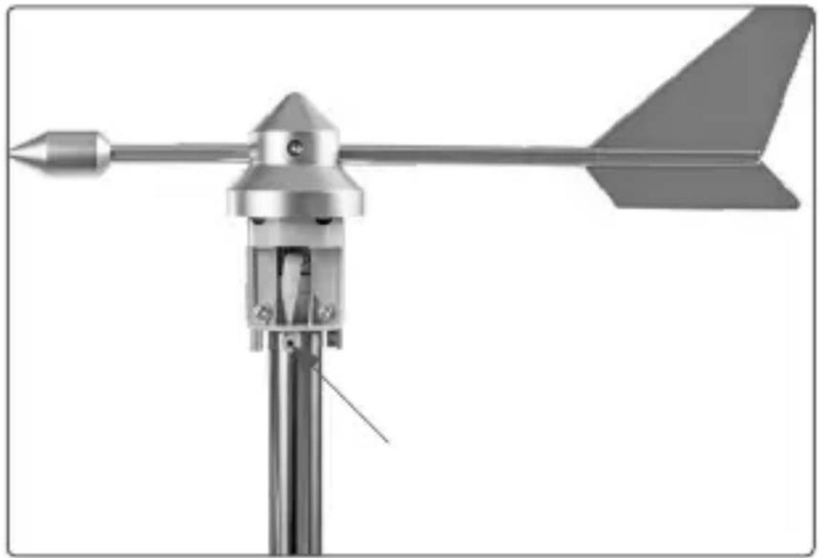
Technical illustration of a weather vane with an arrowhead and pointer, mounted on a pole (no text or symbols)- Turn the supplied screws into the screw holes (front and back side) to fasten the wind direction sensor.
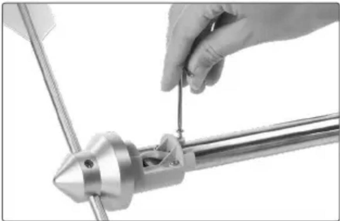
natural_image
Close-up of a hand using a tool to adjust or install a metallic mechanical component (no visible text or symbols)- Slide the cover onto pipe 2 from the bottom to the top until it reaches its end stop.
- Turn the cover anti-clockwise to fix it.
Step 2:
- Remove the anemometer (F) from its packaging.
- Put the anemometer to pipe 3 (H) above the main sensor (G).
- Please make sure that the notch of the rotary axis matches with the screw hole.
- Fasten the anemometer with the screw.
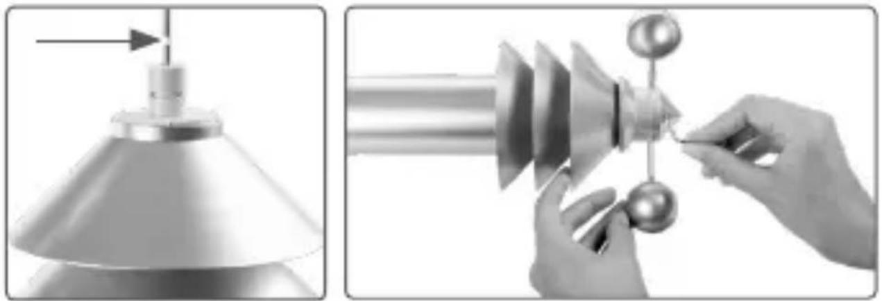
natural_image
Two-step industrial process showing a conical lamp and a rotating mechanical component being handled by hands (no text or symbols visible)Step 3:
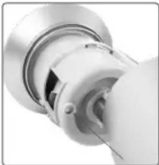
- Loosen the cover of the rain sensor by slightly turning it clockwise and slide it down. Loosen the safety strip of the rain sensor and make sure that the rainfall sensor and the counter rocker are inserted correctly (see „10.2 Cleaning the rain sensor“ on page 66). The counter rocker should be able to change over smoothly.
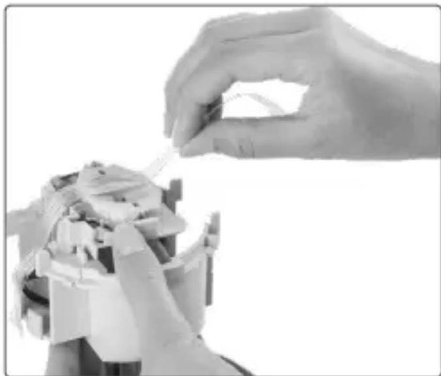
natural_image
Close-up of a hand holding a small object, possibly a robotic arm or mechanical component (no visible text or symbols)- Remove the collecting funnel (A) of the rain sensor (B) from the packaging.
- Place the collecting funnel onto the sensor support of pipe 1 (C) from above and latch it into place by turning it clockwise.
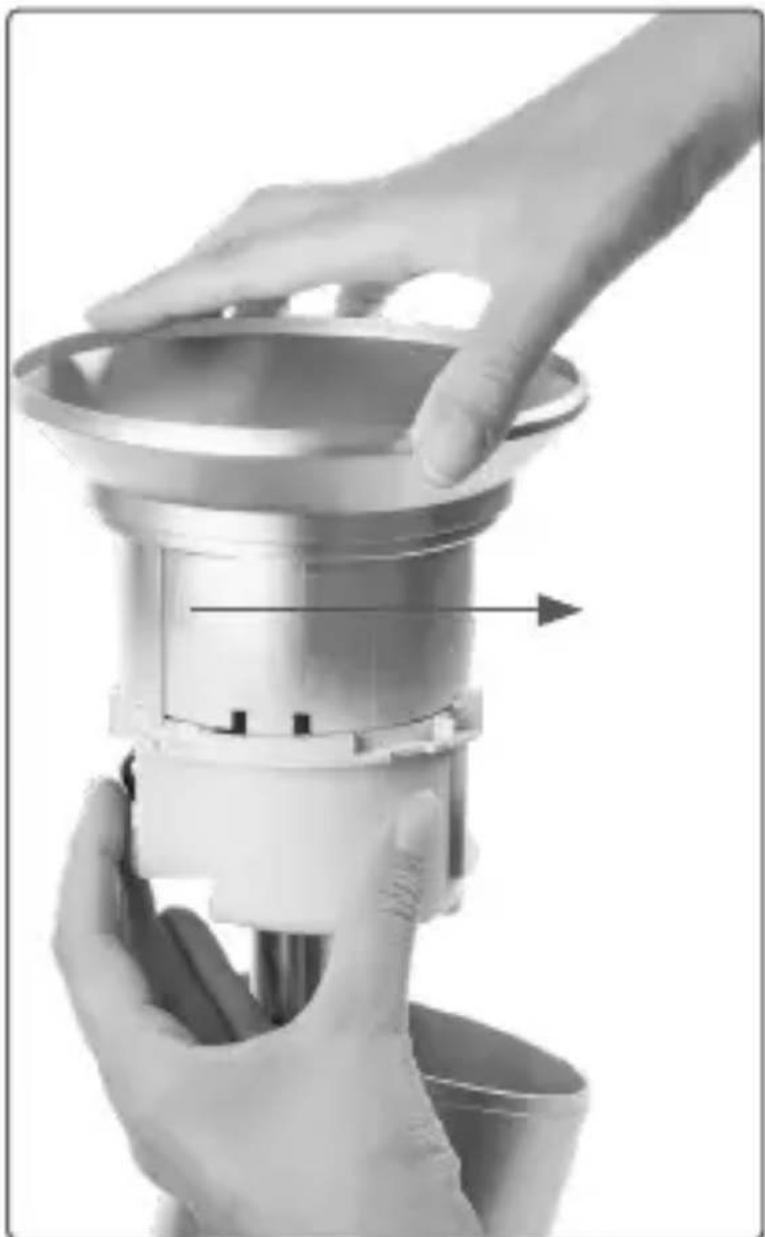
natural_image
Close-up of hands operating a stainless steel kitchen appliance with a handle, showing internal components and a directional arrow (no text or symbols)- Slide the cover from the bottom over the sensor support and latch it into place by turning it anti-clockwise in the sensor support.

natural_image
Hand holding a metallic cylindrical object with a flared top, mounted on a stand (no visible text or symbols)
In doing so, ensure that the positions of the cover drain hole and the sensor support line up (the housing drain hole should be facing outwards).
natural_image
Close-up of a metallic mechanical component with circular and radial features (no visible text or symbols)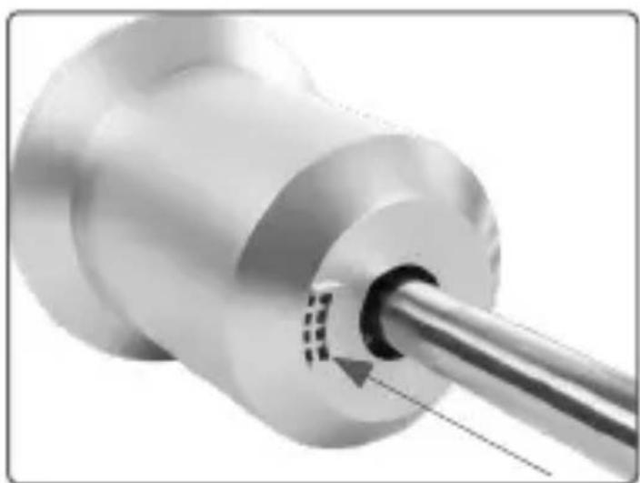
natural_image
Close-up of a metallic mechanical component with a cylindrical shaft and circular base (no visible text or symbols)Step 4:
- Remove the pipes of the stainless steel mast (I) from the packaging.
- Join the pipes together and position the notch-es of the single pipes on top of each other. The previously assembled weather sensor is fixed to the end of the pipe that is marked with a sticker.
- Place the fully assembled sensor within the potential transmission radius (up to 400 m typically in the open air, with damping caused by building walls taken into account). Choose a free position in which it is possible for rain to fall directly into the rain sensor, but where there is no risk of inaccurate wind measurements caused by nearby buildings, trees, etc.

It may be placed in a sunny location since the temperature sensor is located in a shaded, ventilated area of the housing.
- Push the assembled end of the stainless steel mast (I) into the ground until you are sure that the sensor will be stable.
If the weather sensor topples over, it may cause injury or damage to vehicles and objects.
6 First start-up
6.1 Teaching-in

Please read this entire section before starting the teach-in procedure.

First set up your Homematic IP Access Point via the Homematic IP app to enable operation of other Homematic IP devices within your system. For further information, please refer to the operating manual of the Access Point.
You can connect the device either to the Access Point or to the Homematic Central Control Unit CCU2. For detailed information, please refer to the Homematic IP User Guide, available for download in the download area of www.eQ-3.de.
To teach-in the weather sensor to the Access Point, please proceed as follows:
- Open the Homematic IP app on your smartphone.
- Select the menu item "Teach-in device".
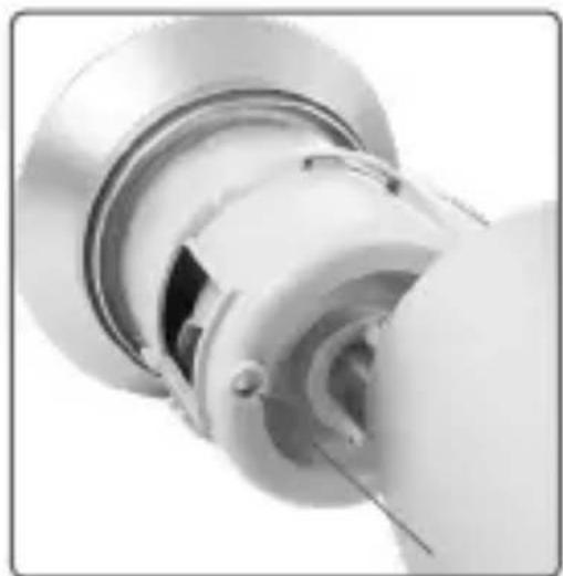
- Loosen the cover of the main sensor (G) by turning the cylinder clockwise and pulling it downwards.
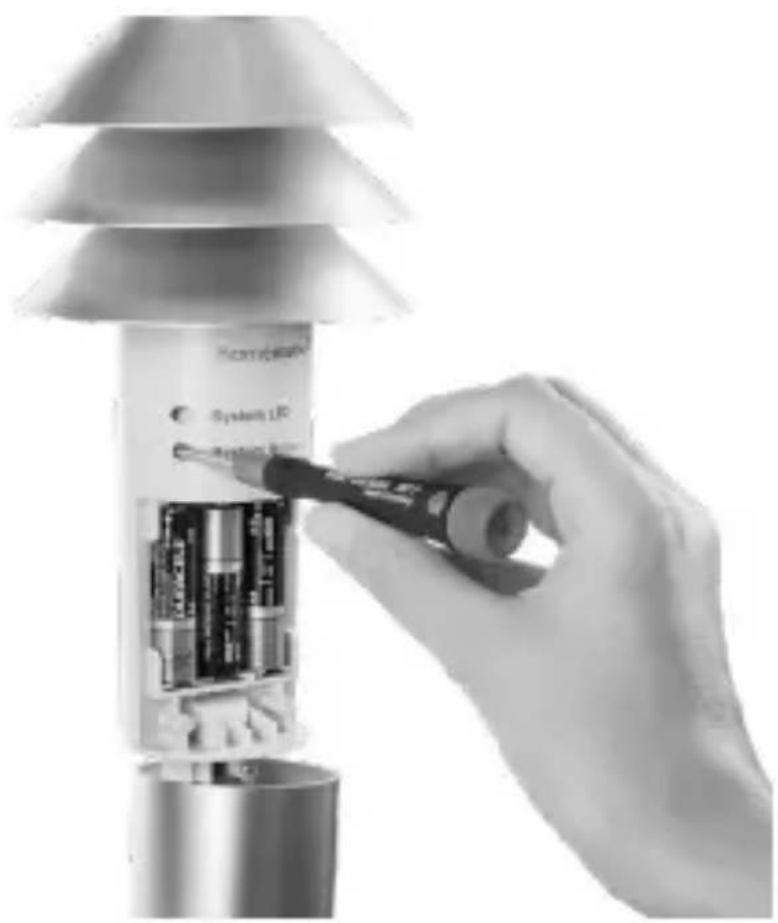
- Insert three 1.5 V LR6/mignon/AA batteries into the battery compartment (L) (see figure 3) to
activate the teach-in mode. The system LED (J) starts flashing. Pairing mode remains activated for 3 minutes.

You can manually start the teach-in mode for another 3 minutes by pressing the system button (K) briefly using a pointed object (see figure 4).
- Your device will automatically appear in the Homematic IP app.
- To confirm, please enter the last four digits of the device number (SGTIN) in your app or scan the QR code. Therefore, please see the sticker supplied or attached to the device.
- Please wait until teach-in is completed.
- If teaching-in was successful, the system LED lights up green. The device is now ready for use.
- If the system LED lights up red, please try again.
- In the app, give the device a name and allocate it to a room.
- Slide the cover from the bottom onto the main sensor and latch it into place by turning it anti-clockwise.
6.2 Alignment of the weathervane
To enable the definition of the wind direction, the weather sensor must be aligned during the first set-up (after teaching-in) so that it is pointing north. To do this, please
proceed as follows:
- Align the weathervane (E) of the weather sensor so that it is pointing north. Therefore, we recommend to use an analogue or electronic compass.

If you need to, you can fix the weathervane in this position using a piece of double-sided adhesive tape on the housing.
- Loosen the cover of the main sensor (G) by turning the cylinder clockwise and pulling it downwards.
- Remove the insulation strip from the battery compartment (L) and insert three new 1.5 V LR6/mignon/AA batteries (if required), observing the correct polarity as indicated by the markings (see fig. 3).
- Press and hold down the system button (K) using a pointed object, e.g. a pen (see fig. 4) until the system LED (J) slowly starts flashing orange.
- Release the system button and press it again shortly to define the northern alignment. The system LED lights up green for confirmation. If the procedure failed, the system LED lights up red. In this case, please check if the device has been mounted correctly and try again.
- If required, remove the adhesive tape from the weathervane.
- Close the housing again by pushing and turning the cover clockwise until it latches into place.
7 Replacing batteries
If an empty battery is displayed via the app or the device (see „8.4 Error codes and flashing sequences“ on page 62), replace the used batteries by three new LR6/mignon/AA batteries. You must observe the correct battery polarity.
To replace the batteries of the weather sensor, please proceed as follows:
- Loosen the cover of the main sensor (G) by turning the cylinder clockwise and pulling it downwards.
- Remove the empty batteries from the battery compartment (L).
- Insert three new 1.5 V LR6/mignon/AA batteries into the battery compartment, making sure that you insert them the right way round (see figure 3).
- Close the housing again by pushing and turning the cylinder clockwise until it latches into place.
Once the batteries have been inserted, the weather sensor will perform a self-test (approx. 2 seconds). Afterwards, initialisation is carried out. The LED test display will indicate that initialisation is complete as the system LED (J) lights up orange and green.

Caution! There is a risk of explosion if the battery is not replaced correctly. Replace only with the same or equivalent type. Never recharge standard batteries. Do not throw the batteries into a fire. Do not expose batteries to excessive heat. Do not short-circuit batteries. Doing so will present a risk of explosion.
natural_image
Two recycling symbols: a trash bin with crossed lines and a recycling symbol with crossed lines (no text or labels)Used batteries should not be disposed of with regular domestic waste! Instead, take them to your local battery disposal point.
8 Troubleshooting
8.1 Weak batteries
Provided that the voltage value permits it, the weather sensor will remain ready for operation also if the battery voltage is low. Depending on the particular load, it may be possible to send transmissions again repeatedly, once the batteries have been allowed a brief recovery period.
If the voltage drops too far during transmission, this will be displayed on the device or via the Homematic IP app (see „8.4 Error codes and flashing sequences“ on page 62). In this case, replace the empty batteries by three new batteries (s. „7 Replacing batteries“ on page 59).
8.2 Command not confirmed
If at least one receiver does not confirm a command, the system LED (K) lights up red at the end of the failed transmission process. The failed transmission may be caused by radio interference (see „12 General information about radio operation“ on page 71). This may be caused by the following:
- Receiver cannot be reached.
- Receiver is unable to execute the command (load failure, mechanical blockade, etc.).
- Receiver is defective.
8.3 Duty cycle
The duty cycle is a legally regulated limit of the transmission time of devices in the 868 MHz range. The aim of this regulation is to safeguard the operation of all devices working in the 868 MHz range.
In the 868 MHz frequency range we use, the maximum transmission time of any device is 1% of an hour (i.e. 36 seconds in an hour). Devices must cease transmission when they reach the 1% limit until this time restriction comes to an end. Homematic IP devices are designed and produced with 100% conformity to this regulation.
During normal operation, the duty cycle is not usually reached. However, repeated and radio-intensive teach-in processes mean that it may be reached in isolated instances during start-up or initial installation of a system. If the duty cycle is exceeded, this is indicated by one long
red lighting of the system LED (J), and may manifest itself in the device temporarily working incorrectly. The device starts working correctly again after a short period (max. 1 hour).
8.4 Error codes and flashing sequences
| Flashing code Meaning Solution | ||
| Short orange flashing | Radio transmission/attempting to transmit/data transmission | Wait until the transmission is completed. |
| 1x long green lighting | Transmission confirmed | You can continue operation. |
| 1x long red lighting | Transmission failed or duty cycle limit is reached | Please try again (see sec. „8.2 Command not confirmed“ on page 61 or „8.3 Duty cycle“ on page 61). |
| Short orange flashing (every 10 s) | Teach-in mode active | Please enter the last four numbers of the device serial number to confirm (see „6.1 Teaching-in“ on page 56). |
| Slow orange flashing | Alignment to the north (see „6 First start-up“ on page 56). | Briefly press the system button (L) to finish the alignment to the north. |
| Short orange lighting (after green or red confirmation) | Batteries empty Re | Replace the batteries of the device (see „7 Replacing bat-teries“ on page 59). |
| 6x long red flashing | Device defective P | Please see your app for error message or contact your retailer. |
| 1x orange and 1 x green lighting | Test display/ system start | Once the test display has stopped, you can continue. |
9 Restoring the factory settings

The factory settings of the device can be restored. If you do this, you will lose all your settings.
To restore the factory settings of the weather sensor, please proceed as follows:
- Loosen the cover of the main sensor (G) by turning the cylinder clockwise and pulling it downwards.
- Remove a battery.
- Insert the battery and press and hold down the system button (K) at the same time using a pointed object, e.g. a pen (see fig. 4) until the system LED (J) quickly starts flashing orange.
- Release the system button again.
- Press and hold down the system button again until the system LED lights up green.
- Release the system button to finish restoring of the factory settings.
- Slide the cover from the bottom onto the main sensor and latch it into place by turning it anti-clockwise.
The system LED stops flashing and the device performs a restart. After the restart, you can again integrate your device into your Homematic IP system.
10 Maintenance and cleaning
10.1 General information

This device does not require you to carry out any maintenance other than replacing the battery and cleaning the device when necessary. Enlist the help of an expert to carry out any maintenance or repairs.
The weather sensor will need to be cleaned from time to time to remove the dirt that will accumulate on it. When you do this, you should also check that the wind sensor can move easily and that the sensors are properly seated on their supports.
Clean the product using a soft, lint-free cloth that is clean and dry. You may dampen the cloth a little with lukewarm water in order to remove more stubborn marks. Make sure that no moisture will ingress into the housing. Do not use any detergents containing solvents, as they could corrode the plastic housing and label.

Check that your product is safe from a technical point of view (that the housing is not damaged, for example) on a regular basis. If you have reason to believe that it is no longer safe to operate the de-
vice, put it out of service. Remove the battery pack to safeguard the device against unintentional operation.
Safe operation may no longer be possible if the device:
• shows signs of external damage,
- no longer functions,
• has been stored under unfavourable conditions or
- has been exposed to severe transport conditions.
If not used for any length of time (e.g. when in storage), remove the batteries to avoid damages caused by leaking, etc.
10.2 Cleaning the rain sensor
Depending on the location, leaves, dirt particles transported by the wind, sand, branches, etc., may get into the rain sensor's (A) collecting funnel (B). Larger items may block the flow of rainwater. Sand can also accumulate in the counter rocker: as the amount increases, this causes the measurement results to be less accurate. Consequently, the rain sensor must be cleaned from time to time; this must be done at least once a year, however.
- Loosen the collecting funnel of the rain sensor by slightly turning it clockwise and lift it off.
- Loosen the cover of the rain sensor by slightly turning it clockwise and slide it down.
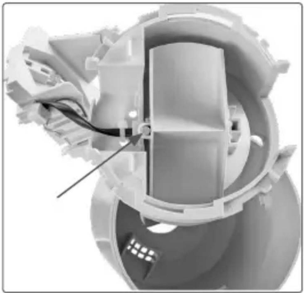
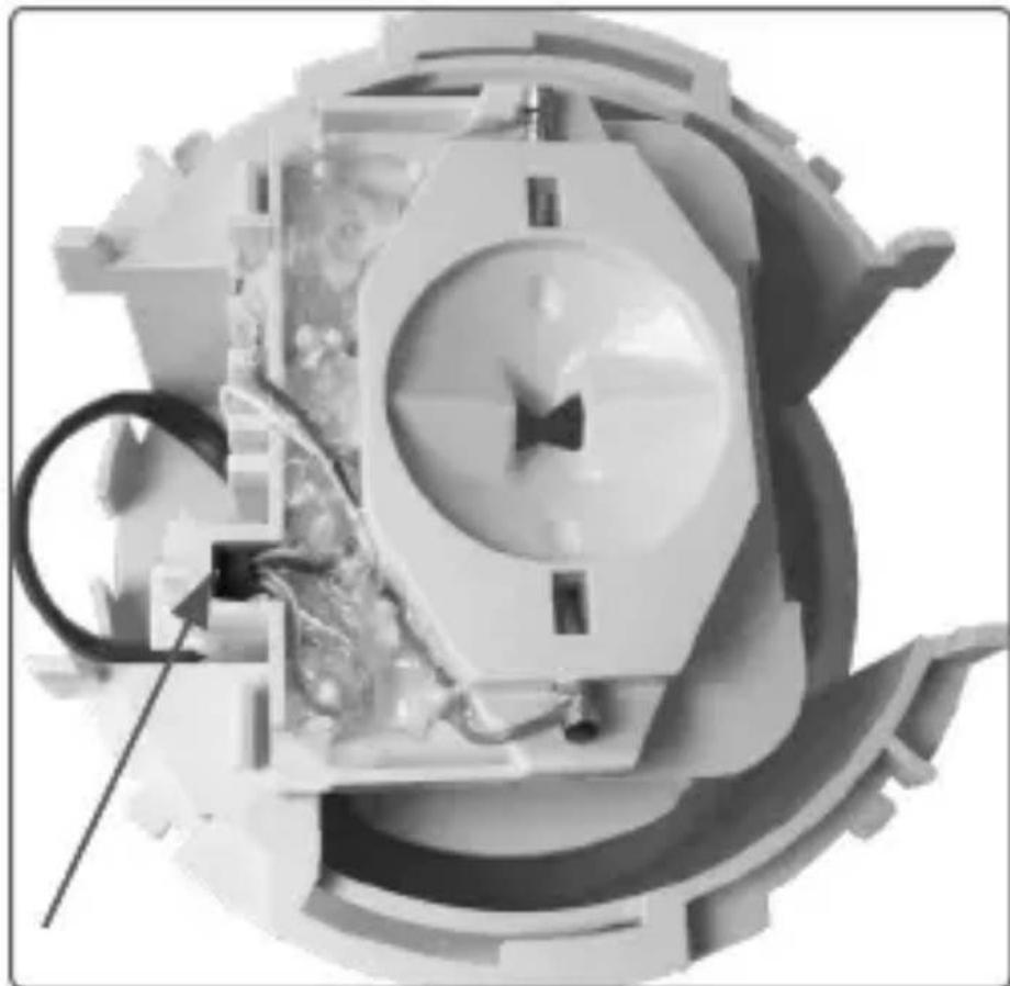
- Detach the rain sensor from above, move it to the side with the cable and remove the counter rocker.
- Clean the collecting funnel, contacts, counter rocker and drain hole in the bottom of the housing to remove any residues.
- Place the counter rocker back in its holder. In doing so, the counter rocker magnet must be at the side facing the cable.
natural_image
Cross-sectional view of a mechanical component with internal structure and a cable inserted (no visible text or symbols)- Place the rain sensor in its holder. It will automatically take hold of the counter rocker. The rain sensor cable and counter rocker magnet must be at the same side.
natural_image
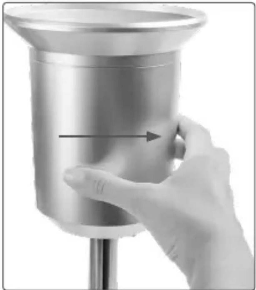
Cross-sectional view of a mechanical device with internal components and no visible text or symbols- Place the collecting funnel onto the sensor support from above and latch it into place by turning it clockwise.
- Slide the cover from the bottom over the sensor support and latch it into place by turning it anti-clockwise in the sensor support.
natural_image
Hand holding a metallic funnel-shaped object with an arrow indicating direction (no text or symbols visible)
In doing so, ensure that the positions of the cover drain hole and the sensor support line up (the housing drain hole should be facing outwards).
natural_image
Close-up of a metallic mechanical component with a cylindrical housing and a curved handle (no visible text or symbols)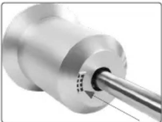
natural_image
Close-up of a metallic cylindrical mechanical component with a metal rod inserted, showing internal features (no text or symbols visible)11 Information regarding the brightness sensor
You can use the collected values of the brightness sensor for controlling other Homematic IP devices. For example, your shutters can be moved down in case of strong sunlight in connection with a Homematic IP Shutter Actuator. Or your awning is extended in case of sunshine offering sun protection while you are on the terrace. The detected brightness of the brightness sensor is displayed in the Homematic IP app on a scale from 0-100,000. The higher the value, the brighter it is. The value is used only for orientation and is not equal to brightness in lux.
12 General information about radio operation
Radio transmission is performed on a non-exclusive transmission path, which means that there is a possibility of interference occurring. Interference can also be caused by switching operations, electrical motors or defective electrical devices.
The range of transmission within buildings can differ greatly from that available in the open air. Besides the transmitting power and the reception characteristics of the receiver, environmental factors such as humidity in the vicinity have an important role to play, as do on-site structural/screening conditions.
Hereby, eQ-3 AG, Maiburger Str. 29, 26789 Leer/Germany declares that the radio equipment type Homematic IP HmlP-SWO-PR is in compliance with Directive 2014/53/EU. The full text of the EU declaration of conformity is available at the following internet address: www.eq-3.com
13 Technical specifications
Device short description: HmIP-SWO-PR
Supply voltage: 3x 1.5 V LR6/mignon/
AA
Current consumption: 50 mA max.
Battery life: 2 years (typ.)
Degree of protection: IP22
Ambient temperature: -20 to +55 °C
Dimensions (W x H x D): 40 x 65 x 15 cm
(not incl. mast)
Dimensions stainless
steel mast (h x ø) 1.58 m x 25 mm
Weight: 1417 g (incl. batteries)
Radio frequency band: 868.0-868.6 MHz
869.4-869.65 MHz
Maximum radiated power: 10 dBm
Receiver category: SRD category 2
Typ. open area RF range: 400 m
Method of operation: Type 1
Degree of pollution: 2
Measurement interval: between 120 and 184 s
| Parameter Range Resolution | Toler- | ance |
| Tempera-ture | -20 to +55 °C 0.1 °C typ.: | ±0,3 °C max.: ±0.4 °C (at 0 to 55 °C) |
| Humidity (relative) | 1 to 99 % 1 % typ.: | ±3 % max.: ±4.5 % (at 20 to 80 %) |
| Brightness (relative) | 0 to 100,000 0 1 / | |
| Rainfall volume | 0 to 966 mm < 0.3 mm / | |
| Wind velocity | 0 to 200 km/h 1 km/h / | |
| Wind direction | 0 to 355° 5° ± 2.5° | |
| Wind direction fluctuation range | 0 to ±146.25° ± 11.25° ± 5.5° |
Subject to technical changes.
Instructions for disposal
natural_image
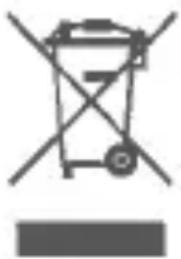
Symbol of a recycling bin with no text or numbers presentDo not dispose of the device with regular domestic waste! Electronic equipment must be disposed of at local collection points for waste electronic equipment in compliance with the Waste Electrical and Electronic Equipment Directive.
Information about conformity

The CE sign is a free trading sign addressed exclusively to the authorities and does not include any warranty of any properties.

For technical support, please contact your retailer.
Kostenloser Download der Homematic IP App! Free download of the Homematic IP app!

text_image
Blue QR code image, scannable for digital information retrieval
text_image
Download on the App Store
text_image
Blue QR code image containing encoded data, no visible text or symbols beyond the matrix pattern
text_image
ANDROID APP ON Google playBevollmächtigter des Herstellers: Manufacturer's authorised representative:

eQ-3 AG Maiburger Straße 29 26789 Leer / GERMANY www.eQ-3.de