
FS-1028MFP/KL3 - Printer KYOCERA - Free user manual and instructions
Find the device manual for free FS-1028MFP/KL3 KYOCERA in PDF.


User questions about FS-1028MFP/KL3 KYOCERA
0 question about this device. Answer the ones you know or ask your own.
Ask a new question about this device
Download the instructions for your Printer in PDF format for free! Find your manual FS-1028MFP/KL3 - KYOCERA and take your electronic device back in hand. On this page are published all the documents necessary for the use of your device. FS-1028MFP/KL3 by KYOCERA.
USER MANUAL FS-1028MFP/KL3 KYOCERA
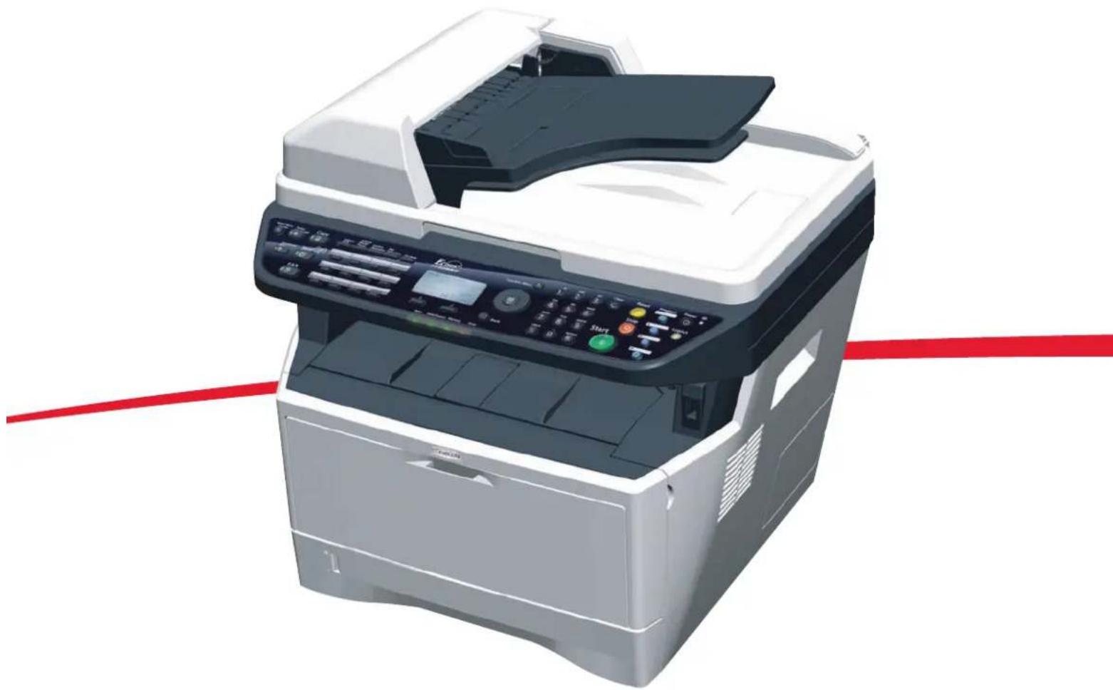
FS-1028MFP/FS-1128MFP
SETUP GUIDE
natural_image
Illustration of a modern open-plan printer with control panel and paper tray (no visible text or symbols)Introduction
About this Guide
This guide explains the following setting method necessary to use this machine.
Installation of the machine
- Unpacking
- Installing Toner Container
- Loading Paper
- Connecting Cables
- Connecting Modular Cords
Operation at the machine panel
- Selecting Language
- Date and Time Settings
- Setting Network Interface Parameters
Operation at the PC
- Accessing COMMAND CENTER (Internal HTML web page)
- Sharing Folder to use Scan to SMB
- Installing Printer Driver
- Setting TWAIN Driver
- Setting WIA Driver
IMPORTANT: Please read safety information on the Operation Guide before installing this machine.
Trademark Information
- Windows is a registered trademark of Microsoft Corporation in the U.S.A. and/or other countries.
- Windows XP and Windows Vista are trademarks of Microsoft Corporation.
- This machine contains the software having modules developed by Independent JPEG Group.
All other company and product names contained in this guide are trademarks or registered trademarks of their respective companies. The designations ^™ and ^® will not be used in this guide.
1 Preparations
Clearance
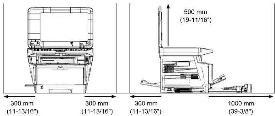
text_image
300 mm (11-13/16") 300 mm (11-13/16") 500 mm (19-11/16") 300 mm (11-13/16") 1000 mm (39-3/8)Environment
• Temperature: 10 to 32.5 °C (50 to 90.5 °F)
• Humidity: 15 to 80 %RH
• Power Supply: 120 V AC, 60 Hz, 7.4 A / 220 to 240 V AC, 50/60 Hz, 3.8 A

CAUTION: Be sure to provide enough space around machine. Prolonged use without sufficient clearance may cause overheating.
Unpacking
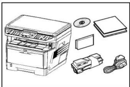
1 Unpack the machine and all its included components.
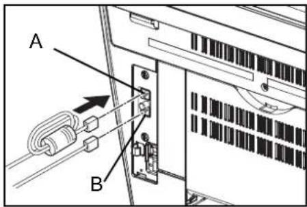
If the machine is FS-1128MFP, the modular cord with the attached ferrite core is enclosed.
natural_image
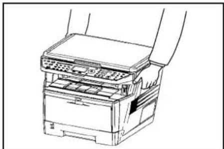
Line drawing of a printer with various electronic components including CD, DVD, and accessories (no text or labels)IMPORTANT: Place the machine in a stable position. When carrying the printer, always hold the right and left sides as shown.
natural_image
Line drawing of a printer with paper feeding into a stack (no text or symbols)2 Remove the packing tape and the protective sheet.
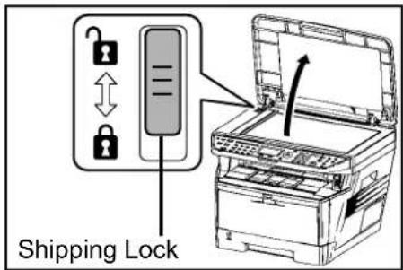
3 Slide the Shipping Lock to the unlock position.
text_image
Shipping LockIMPORTANT: When installing the Document Processor, refer to Installation Guide attached to the Document Processor.
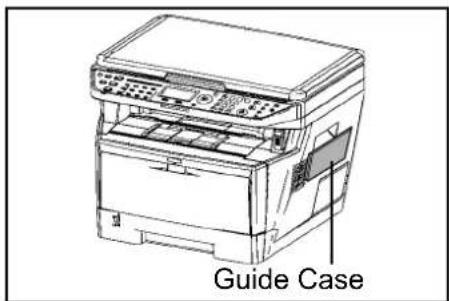
4 Attach the Guide Case to the machine right as required.
text_image
Guide CaseInstalling Toner Container
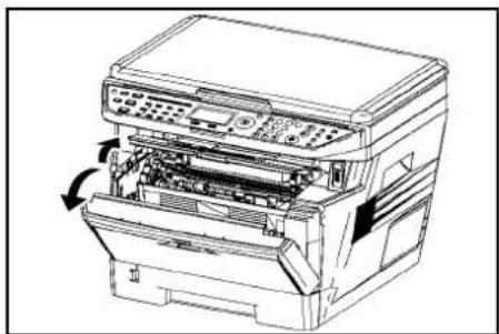
1 Open the front cover.
natural_image
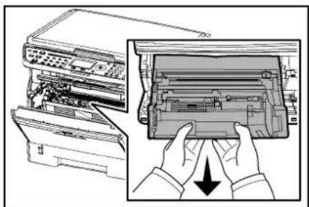
Line drawing of a printer with internal components and a scroll wheel (no text or symbols)2 Remove the process unit from the machine.
natural_image
Illustration of a printer's internal structure being inserted into a device, showing hands holding the lid (no text or symbols present)IMPORTANT: Place the process unit on a clean, level surface where it will not be exposed to any sort of impact or shock. The drum in the process unit is sensitive to light and should not be exposed to normal office lighting for more than five minutes.
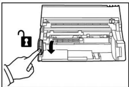
3 Check the lock lever to the UNLOCK position.
text_image
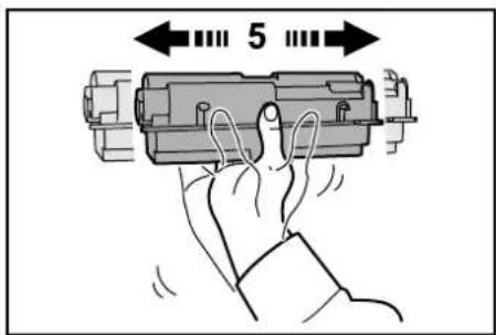
Diagram showing a hand pressing a lock mechanism into a printer's internal structure with an open lock icon and arrow indicating the lock mechanism.4 Shake the toner container horizontally 5 or 6 times so that the toner inside becomes evenly distributed.
text_image
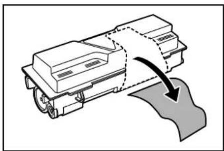
55 Remove the orange protective seal.
natural_image
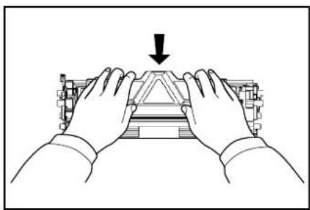
Diagram of a mechanical component with a curved arrow indicating motion or force, no text or symbols present6 Align the knob on the left side of the container with the groove in the process unit and place the toner container into the process unit.
natural_image
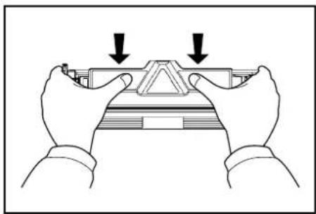
Illustration of hands assembling a mechanical component with a downward arrow (no text or symbols)7 Push on the PUSH marks on the toner container until the container clicks into place.
natural_image
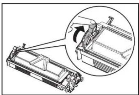
Illustration of two hands holding a mechanical component with downward arrows indicating compression or disassembly (no text or symbols)8 Push the lock lever back into its LOCK position (away from you).
natural_image
Mechanical assembly diagram showing a component being inserted into a housing, with an inset close-up highlighting the mechanism (no text or symbols present)9 Align the pins on both sides of the process unit with the guides inside the machine, and slide the process unit into the machine until it stops.

natural_image
Line drawing of hands operating a computer motherboard with an arrow indicating a component (no text or symbols present)10 Close the front cover.
Loading Paper
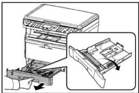
1 Carefully pull the cassette all the way out of the machine and remove the protective packing from inside the cassette.
natural_image
Illustration of a printer's internal structure with a hand inserting a tray into the base (no text or symbols)2 Adjust the paper length by pressing in on the release buttons and sliding paper stopper to fit the size of the paper. The paper sizes are marked on the bottom of the cassette.

natural_image
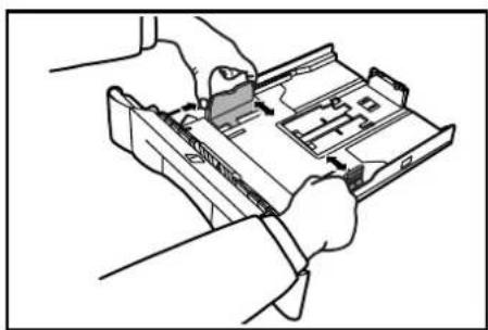
Technical diagram of a mechanical assembly with an inset showing internal components (no text or symbols)3 Adjust the paper width by pressing in on the release buttons and sliding the guides to fit the width of the paper.
natural_image
Line drawing of hands assembling or handling a device with internal components (no text or symbols)4 Fan the paper, then tap it on a level surface to avoid media jams or skewed printing.
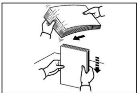
natural_image
Illustration of two hands holding a stack of papers and a blank sheet, with arrows indicating motion (no text or symbols)5 Place the paper in the cassette, with side to be printed downward, so that the leading edge is aligned against the paper stopper.
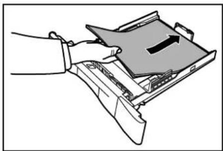
natural_image
Illustration of a hand inserting a device into a folder with an arrow indicating direction (no text or symbols present)IMPORTANT: Do not exceed the upper limit of the cassette. Otherwise, it may cause paper jams.
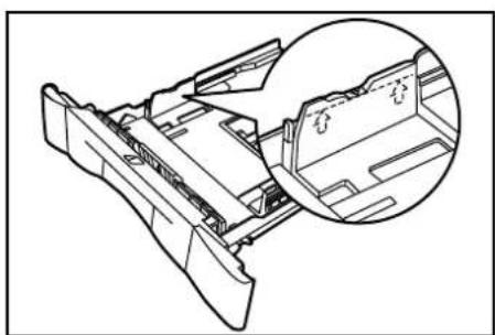
natural_image
Technical line drawing of a mechanical component with an inset magnified view showing internal structure (no text or symbols)6 Push the cassette securely all the way back into the machine until it stops.
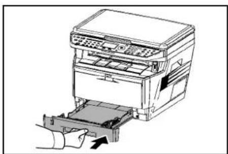
natural_image
Line drawing of a printer being inserted into a paper holder, with no visible text or symbolsConnecting Cables
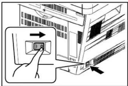
1 Turn the power switch off (O).
text_image
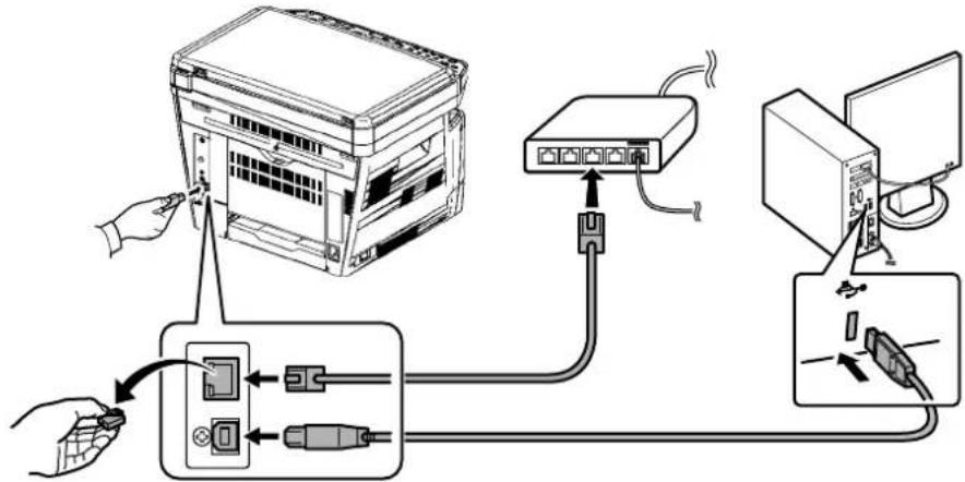
Diagram showing a hand pressing a button on a computer interface with an arrow indicating direction of action.2 Connect the machine to the PC or your network device. When using the network interface, remove the cap. These cables are sold separately.
flowchart
graph TD
    A["Hand"] --> B["Switch"]
    B --> C["Switch switch"]
    C --> D["Computer Interface"]
    D --> E["Wireless Cable"]
    style A fill:#f9f,stroke:#333
    style B fill:#ccf,stroke:#333
    style C fill:#cfc,stroke:#333
    style D fill:#fcc,stroke:#333
    style E fill:#cff,stroke:#333
Available Standard Interfaces:
| Interface Function Necessary Cable | ||
| Network Interface | Printer/Scanner/ Network FAX | LAN (10Base-T or 100Base-TX, Shielded) |
| USB Interface Printer/TWAIN/WIA | USB2.0 compatible cable (Hi-Speed USB compliant, Max. 5.0 m, Shielded) | |
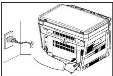
3 Connect the power cord to the machine and the other end into a power outlet.
natural_image
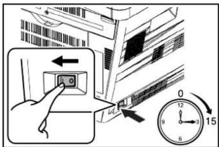
Line drawing of a server rack with an attached power outlet and cable, no text or symbols present4 Turn the power switch on (|). The machine begins to warm up. The machine will begin replenishing the toner; this will take approximately 15 minutes.
Once the toner has been replenished, Ready to copy will appear on the message display.
text_image
Diagram showing a hand pressing a button on a server rack, with a clock indicating 15:00 and directional arrows.Connecting Modular Cords (FS-1128MFP only)
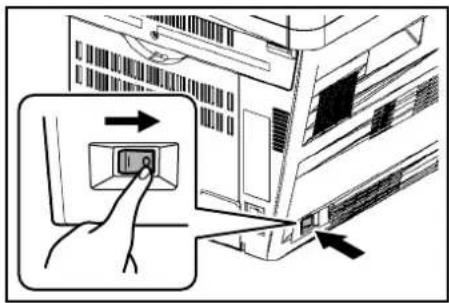
1 Turn the power switch off (O).
text_image
Diagram showing a hand pressing a button on a computer interface with an arrow indicating the process.2 Connect the modular cord with the attached ferrite core to the line jack (A) of the machine. Then, connect the modular cord to the telephone jack (B) of the machine.
text_image
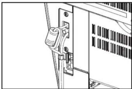
A B3 Route the cords as shown in the figure.
natural_image
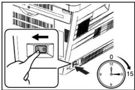
Technical line drawing of a mechanical device with a lock and handle (no text or symbols)4 Turn the power switch on (I). The machine begins to warm up. If the mache is first installation, it will begin replenishing the toner; this will take approximately 15 minutes.
text_image
Diagram showing a hand pressing a button on a server rack, with a clock indicating 15 seconds and directional arrows.Once the toner has been replenished, Ready to copy will appear on the message display.
2 Panel Setup
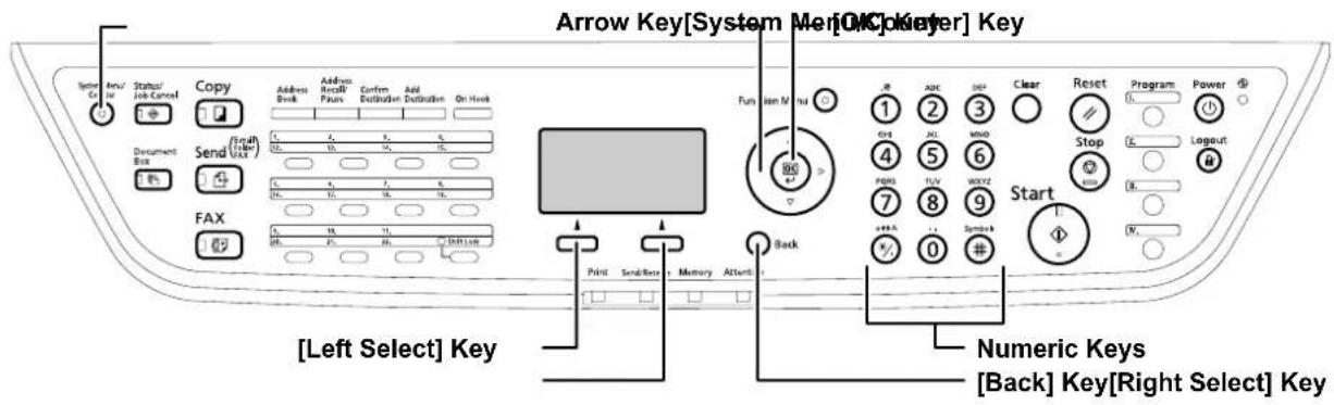
Operation Panel
text_image
Arrow Key[System Mer[OK]Keyer] Key [Left Select] Key Numeric Keys [Back] Key[Right Select] KeySelecting Language
Perform the following procedure to select the language of the message display. The default message language is English.
1 Press [System Menu/Counter]. The Sys. Menu/Count. screen appears.
2 Press or ([Arrow Key]) to select Common Settings.
3 Press [OK]. The Common Settings screen appears.
4 Press or to select Language.
5 Press [OK]. The Language screen appears showing the list of languages.
6 Press or to select the desired language.
7 Press [OK]. The language is set and the Common Settings menu reappears.
Date and Time Settings
Setting the Time Zone
Perform the following procedure to select the time zone.
1 In the Common Settings menu, press or to select Date Setting.
2 Press [OK]. The Date Setting screen appears.
3 Press or to select Time Zone.
4 Press [OK]. The Time Zone screen appears.
5 Press or to select the time zone that you are in.
6 Press [OK]. The time zone is set and the Date Setting menu reappears.
Summer Time Setting
Perform the following procedure to turn the summer (daylight saving) time setting on and off.
NOTE: This setting is valid only in the area where summer time is observed.
1 In the Date Setting menu, press or to select Summer Time.
2 Press [OK]. The Summer Time screen appears.
3 Press or to select whether summer time is enabled.
4 Press [OK]. The summer time is set and the Date Setting menu reappears.
Setting the Current Date and Time
Perform the following procedure to set the current date and time.
NOTE: Periodically check the time that is shown in the message display and adjust as necessary to match the current time.
1 In the Date Setting menu, press or to select Date/Time.
2 Press [OK]. The Date/Time screen (month:day:year) is appears.
3 To set the date, for each field press or as many times as necessary to display the correct value then press to move to the next field.
Use ◀ and ▷ to move the cursor right and left.
4 When the date is correct, press [OK]. The time setting screen (hour:minute:second) is appears.
5 To set the time, for each field press or as many times as necessary to display the correct value then press to move to the next field.
6 Press [OK]. The date and time is set and the Date Setting menu reappears.
Setting Network Interface Parameters
This machine supports TCP/IP and TCP/IP (IPv6) protocols. IP is an abbreviation for Internet Protocol. This machine routinely uses the TCP/IP (IPv4) protocol, but provides a separate setting for the next generation IP, IPv6. Configure the printer's network parameters as appropriate for your PC and your network environment.
IMPORTANT: Check with your network administrator when selecting the network setting. After all network related settings have been done, turn the machine Off and On again.
TCP/IP (Enable/Disable TCP/IP)
This selects the settings for TCP/IP.
1 Press [System Menu/Counter]. The Sys. Menu/Count. screen appears.
2 Press or to select System.
3 Enter the user ID and password to log in.
NOTE: The default settings of user ID and password are both 2800.
4 Press [OK]. The System screen appears.
5 Press or to select Network Setting.
6 Press [OK]. The Network Setting screen appears.
7 Press or to select TCP/IP Setting.
8 Press [OK]. The TCP/IP Setting screen appears.
9 Press or to select TCP/IP.
10 Press [OK]. The TCP/IP screen appears.
11 Press or to select whether TCP/IP is enabled.
12 Press [OK]. The TCP/IP is set and the TCP/IP Setting menu reappears.
IPv4 Settings (TCP/IP IPv4 settings)
This selects the settings for TCP/IP (IPv4).
1 In the TCP/IP Setting menu, press or to select IPv4 Setting.
2 Press [OK]. The IPv4 Setting menu screen appears.
The options available in the TCP/IP (IPv4) settings are as follows:
- DHCP (DHCP setting)
• Bonjour (Bonjour setting)
• IP Address (IP address setting) - Subnet Mask (Subnet mask setting)
- Default Gateway (Gateway setting)
DHCP
1 In the IPv4 Setting menu, press or to select DHCP.
2 Press [OK]. The DHCP screen appears.
3 Press or to select whether DHCP is enabled.
4 Press [OK]. The DHCP is set and the IPv4 Setting menu reappears.
Bonjour
1 In the IPv4 Setting menu, press or to select Bonjour.
2 Press [OK]. The Bonjour screen appears.
3 Press or to select whether Bonjour is enabled.
4 Press [OK]. The automatic Bonjour is set and the IPv4 Setting menu reappears.
IP Address
1 In the IPv4 Setting menu, press or to select IP Address.
2 Press [OK]. The IP Address screen appears.
3 Use the arrow keys to set the IP address.
Press and to increase or decrease, respectively, the value at the blinking cursor. You can set any value between 000 and 255.
Use ◀ and ▷ to move the cursor right and left.
4 Press [OK]. The IP address is stored and the IPv4 Setting menu reappears.
Subnet Mask
1 In the IPv4 Setting menu, press or to select Subnet Mask.
2 Press [OK]. The Subnet Mask screen appears.
3 Use the arrow keys to set the subnet mask.
Press and to increase or decrease, respectively, the value at the blinking cursor. You can set any value between 000 and 255.
Use ◀ and ▷ to move the cursor right and left.
4 Press [OK]. The subnet mask is stored and the IPv4 Setting menu reappears.
Default Gateway
1 In the IPv4 Setting menu, press or to select Default Gateway.
2 Press [OK]. The Default Gateway screen appears.
3 Use the arrow keys to set the default gateway.
Press and to increase or decrease, respectively, the value at the blinking cursor. You can set any value between 000 and 255.
Use ◀ and ▷ to move the cursor right and left.
4 Press [OK]. The default gateway is stored and the IPv4 Setting menu reappears.
IPv6 Setting (TCP/IP IPv6 settings)
This selects the settings for TCP/IP (IPv6).
1 In the TCP/IP Setting menu, press or to select IPv6 Setting.
2 Press [OK]. The IPv6 Setting menu screen appears.
The options available in the TCP/IP (IPv6) settings are as follows:
- TCP/IP(IPv6) (Enable/disable TCP/IP (IPv6))
- Prefix Length (Prefix Length setting)
• RA(Stateless) (RA (Stateless) setting) - DHCPv6 (DHCPv6 setting)
TCP/IP(IPv6)
1 In the IPv6 Setting menu, press or to select TCP/IP(IPv6).
2 Press [OK]. The TCP/IP (IPv6) screen appears.
3 Press or to select whether TCP/IP (IPv6) is enabled.
4 Press [OK]. The TCP/IP(IPv6) is set and the IPv6 Setting menu reappears.
Prefix Length
1 In the IPv6 Setting menu, press or to select Prefix Length.
2 Press [OK]. The Prefix Length screen appears.
3 Use the arrow keys to set the default gateway.
Press or to increase or decrease, respectively, the value at the blinking cursor. You can set any value between 0 and 128.
Use ◀ and ▷ to move the cursor right and left.
4 Press [OK]. The Prefix Length is set and the IPv6 Setting menu reappears.
DHCPv6
1 In the IPv6 Setting menu, press or to select DHCPv6.
2 Press [OK]. The DHCPv6 screen appears.
3 Press or to select whether DHCPv6 is enabled.
4 Press [OK]. The DHCPv6 is set and the IPv6 Setting menu reappears.
RA(Stateless)
1 In the IPv6 Setting menu, press or to select RA(Stateless).
2 Press [OK]. The RA(Stateless) screen appears.
3 Press or to select whether RA(Stateless) is enabled.
4 Press [OK]. The RA(Stateless) is set and the IPv6 Setting menu reappears.
AppleTalk (AppleTalk setting)
AppleTalk is a communications protocol used primarily on Macintosh computers and also refers to the Mac OS network functions. The default setting is On.
1 Press [System Menu/Counter]. The Sys. Menu/Count. screen appears.
2 Press or to select System.
3 Press [OK]. The System screen appears.
4 Press or to select Network Setting.
5 Press [OK]. The Network Setting screen appears.
6 Press or to select AppleTalk.
7 Press [OK]. The AppleTalk screen appears.
8 Press or to select whether AppleTalk is enabled.
9 Press [OK]. The AppleTalk is set and the Network Setting menu reappears.
3 Accessing COMMAND CENTER
COMMAND CENTER refers to the internal HTML web page that is installed in the machine from which you can verify the operating status of the machine and make settings related to security, network printing, e-mail transmission and advanced networking.
1 Run the web browser.
2 In Address or Location, enter the machine IP address as the URL, e.g. http://192.168.110.171/. The web page displays basic information about the machine and COMMAND CENTER as well as the current status of the machine.
3 Select a category from the navigation bar on the left to view and set values for that category.
4 Setting Administrator Password restricts general users' access to pages other than the Start page. For security purposes, setting the Administrator password is highly recommended. The default Administrator password is factory-set as admin00.
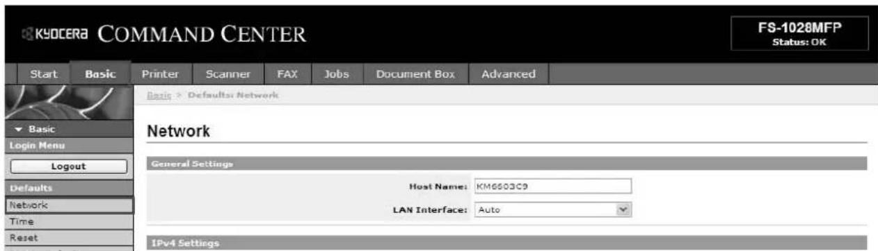
Network Settings
This page allows you to make the settings that are required for network printing and sending e-mail. You must restart this machine after you have completed these settings in order to properly register the content of those settings in the machine.
text_image
KYOCERA COMMAND CENTER FS-1028MFP Status: OK Start Basic Printer Scanner FAX Jobs Document Box Advanced Basic > Default: Network Network General Settings Host Name: KM6503C9 LAN Interface: Auto Defaults Network Time Reset IPv4 Settings1 Click Basic -> Network.
2 Enter the correct settings in each field. The table below provides a summary of the items displayed on the Network page.
| Item Description | |
| Host Name | Specifies a name for the printing system network component. This name is used as the NetBEUI printer name and as the WSD device name. |
| LAN Interface | Specifies the communication rate from Auto, 10BASE-T-Half, 10BASE-T-Full, 100BASE-TX-Half, and 100BASE-TX-Full. |
| IPv4 Settings DHCP/BOOTP | Specifies whether or not to automatically obtain an IP address using DHCP or BOOTP. |
| IP Address (IPv4) | Assigns the Internet Protocol address on the printing system network component. The format of the IP address is four-byte (32-bit) numbers separated by dots, e.g. 192.168.110.171. |
| Subnet Mask | Specifies the subnet mask of the hosts or network with which the print system is connecting. If you have manually assigned an IP address that starts with a number between 192 and 223, it is recommended that you set the subnet mask to "255.255.255.0." |
| Default Gateway Specifies the IP address of the default gateway. | |
| IPv6 Settings IPv6 | Specifies whether or not to enable the IPv6 protocol. Select On to use the IPv6 protocol. |
| IP Address (IPv6) | Assigns an IPv6 address to the printing system network component. The format of the IPv6 address is a sequence of numbers (128 bit in total) separated by colons, e.g. 2001:db8:3c4d:15::1a2c:1a1f. |
| Prefix Length | Specifies the IPv6 prefix length of the hosts or network with which the print system is connecting. |
| RA (Stateless) | Select On to use RA to configure IPv6 addresses. |
| Default Gateway Specifies the IPv6 address of the default gateway. | |
| DHCPv6 | Specifies whether or not to obtain IPv6 IP addresses by automatic configuration. When RA is turned On, the IP addresses and server information are obtained via DHCPv6 based on the settings of the automatic configuration made under RA (router setting). |
3 Click Submit.
E-mail Settings
The following procedure explains the method for attaching scan data to e-mail for transmission. Scan to e-mail works within the following environments:
- It must have a network environment in which this machine can connect to a mail server. It is recommended that the machine be used in an environment in which it can connect to the mail server at any time over a LAN.
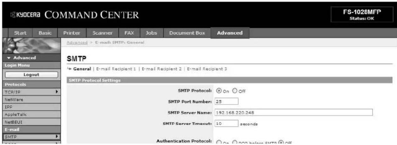
- The SMTP settings must be completed. Use COMMAND CENTER, to register the IP address and the host name of the SMTP server.
- There may be a times where transmission is not possible due to the size of each e-mail item.
The scanner system network component offers e-mail function. SMTP is an embedded protocol to support this function. To use the e-mail function, the scanner system needs connection to an e-mail server using the POP3 protocol.
text_image
KYOCERA COMMAND CENTER FS-1028MFP Status: OK Start Basic Printer Scanner FAX Jobs Document Box Advanced Advanced > E-mail: SMTP General SMTP ► General | E-mail Recipient 1 | E-mail Recipient 2 | E-mail Recipient 3 SMTP Protocol Settings SMTP Protocol: On Off SMTP Port Number: 25 SMTP Server Name: 192.168.220.248 SMTP Server Timcouts: 10 seconds Authentication Protocol: On Off before SMTP Off1 Click Advanced -> SMTP -> General.
2 Enter the correct settings in each field. The table below provides a summary of the items displayed on the SMTP Protocol Settings page.
| Item Description | |
| SMTP Protocol | Enables or disables SMTP protocol. To use e-mail, this protocol must be enabled. |
| SMTP Port Number Set the SMTP Port Number or use the SMTP default port 25. | |
| SMTP Server Name | Enter the SMTP server name or its IP address. If entering the name, rather than the IP address, a DNS server address must also be configured. The DNS server address may be entered on the TCP/IP General tab. |
| SMTP Server Timeout | Sets the timeout in seconds during which this machine tries to connect to the SMTP server. |
| Authentication Protocol | Enables or disables the SMTP authentication protocol or sets POP before SMTP as the protocol. The SMTP authentication supports Microsoft Exchange 2000. |
| Authenticate as | Specifies the user to be authenticated in SMTP authentication. When POP3 User 1 to 3 and iFAX User are set, you can select one of them. If you want to select a different user, select Other and enter the login account name and login password for authentication. |
| Login User Name | When Other is selected for Authenticate as, the account name set here will be used for SMTP authentication. |
| Login Password | When Other is selected for Authenticate as, the password set here will be used for authentication. |
| POP before SMTP Timeout | Enter the timeout in seconds during which this machine tries to connect to the SMTP server when set POP before SMTP as the Authentication Protocol. |
| Test | Tests to confirm that the settings on this page are correct. When the Test button is pressed, this machine tries to connect to the POP3 server. |
| E-mail Size Limit | Enter the maximum size of e-mail that can be sent in Kilobytes. When the value is 0, the limitation for E-mail size is disabled. |
| Sender Address | Enter the E-mail address of the person responsible for the printing system, such as the printer administrator, so that a reply or non-delivery report will go to a person rather than to the machine. The sender address must be entered correctly for SMTP authentication. Note that no mail message can be sent unless the sender's address is specified. |
| Signature | Enter the signature. The signature is free form text that will appear at the end of the e-mail body. It is often used for further identification of the machine. |
| Domain Restriction | Enter the domain names that can be permitted or rejected. You can also specify the e-mail addresses. |
3 Click Submit.
Enabling SMB Function
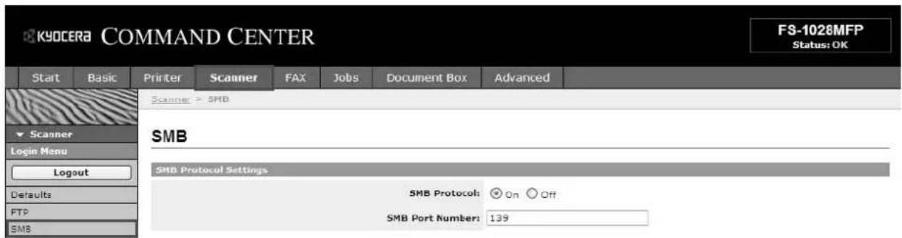
Stores the image data of scanned originals as a file in a desired folder on your PC. Enables SMB parameters in COMMAND CENTER.
In order to access the PC, you must consult the administrator to check the following information on each server and register them to this machine.
- Login user name and Password (using operation panel)
- Host name or IP address of the PC
- Port number
- Path (path from the home directory of the PC to the folder for storage)
• Shares the destination's PC folder (Refer to Sharing PC Folder on page 22)
Login username and Login password are identical to the Windows User logon on the PC from which the accessed folder is stored. User access rights for the machine to the necessary folder should be registered within Windows on that PC.
text_image
KYOCERA COMMAND CENTER FS-1028MFP Status: OK Start Basic Printer Scanner FAX Jobs Document Box Advanced Scanner > SMB Scanner Login Menu Logout Defaults FTP SMB SMB Protocol Settings SMB Protocol: On Off SMB Port Number: 1391 Click Scanner -> SMB.
2 Enter the correct settings in each field. The table below provides a summary of the items displayed on the scanner SMB page.
| Item Description | |
| SMB Protocol | Switches the SMB Protocol On or Off. |
| SMB Port Number | Set the SMB default Port Number or use the SMB default port 139 (For Windows Vista, use 445). |
3 Click Submit.
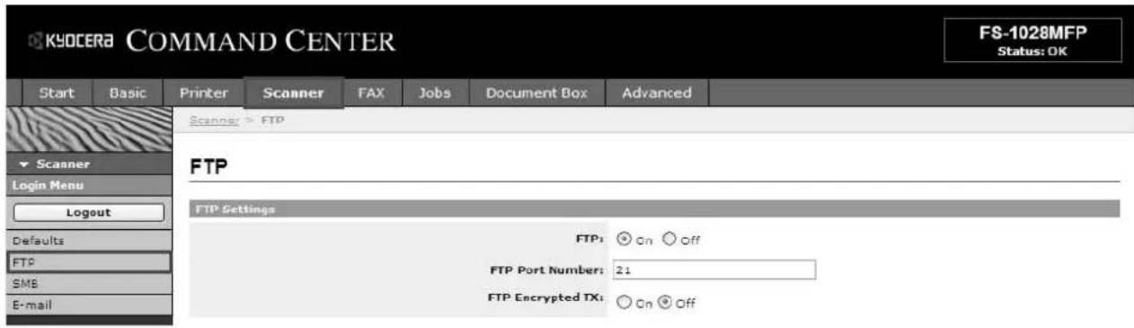
Enabling FTP Function
The FTP transmission function converts the data of originals scanned on this machine to the PDF, TIFF, JPEG, or XPS format and uploads it directly to an FTP server. Enable FTP parameters in COMMAND CENTER.
In order to access a FTP server, you must consult the server administrator to check the following information on each server and register them to this machine.
- Login user name (using operation panel)
- Password (using operation panel)
- Host name or IP address of FTP server
• Port number (normally 21) - Path (path from the home directory of the FTP server to the folder for storage)
• Shares the FTP server
Login username and Login password are identical to the FTP User login. The FTP user account for the machine needs to be installed and administrated at the FTP server.
text_image
KYOCERA COMMAND CENTER Start Basic Printer Scanner FAX Jobs Document Box Advanced Scanner > FTP FTP FTP Settings FTP: ○ On ○ Off FTP Port Number: 21 FTP Encrypted TX: ○ On ○ Off FS-1028MFP Status: OK1 Click Scanner -> FTP.
2 Enter the correct settings in each field. The table below provides a summary of the items displayed on the scanner FTP page.
| Item Description | |
| FTP | Switches FTP On or Off. |
| FTP Port Number Set | the FTP Port Number or use the FTP default port 21. |
| FTP Encrypted TX | This enables or disables Encryption for communication. When turned On, data communications are encrypted using the one of the following algorithms. |
| Encryption | This allows you to specify the encryption algorithm for data communication. You can use more than one algorithms at a time. (This is possible by turning FTP Encrypted TX to On.) |
3 Click Submit.
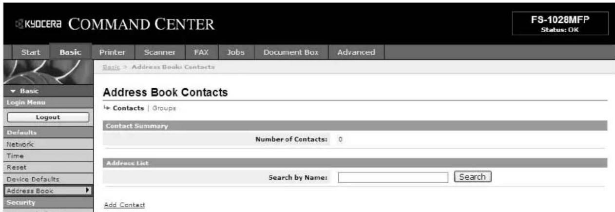
Editing Address Book
This machine has an address book function. When an e-mail address, the path of PC folder (SMB), FTP server's path, FAX, and i-FAX number are registered in the address book, it can transmit directly from the operation panel. This page allows you to add, edit or delete Contacts or Groups.
text_image
KYOCERA COMMAND CENTER FS-1028MFP Status: OK Start Basic Printer Scanner FAX Jobs Document Box Advanced Basic > Address Book Contacts Address Book Contacts + Contacts | Groups Contact Summary Number of Contacts: 0 Address List Search by Name: Search Add ContactAdding a New Contact
1 Open the Address Book Contacts page.
2 Click Add Contact. The Address Book Contacts - Add page opens.
3 Enter the information for the contact to be registered. You can specify a FAX number and i-FAX even if the FAX System is not installed.
4 Click Submit.
Adding a New Group
1 Open the Address Book Groups page.
2 Click Add Group. The Address Book Groups - Add page opens.
3 Enter the number and name of the group.
4 Click Submit. The Address Book Groups - Add Members page opens.
5 Select the members to be added to the created group. Check the members you want to add. The members must be registered before added.
6 After you have selected the members, click Submit. The Address Book Groups - Edit page opens. Click Submit. You can continue editing groups, such as changing group names and adding or deleting members.
4 Sharing PC Folder
To use Scan to SMB (PC) function, a "shared folder" must be set up with the destination computer to receive data.
IMPORTANT: To use Scan to SMB (PC) function, the machine must be connected to a TCP/IP network.
The next section explains how to send data to a domain controlled computer.
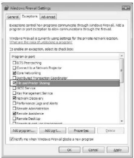
Configuring Windows Firewall (for Windows Vista)
If the destination of files is a Windows Vista-based computer, you must configure Windows Firewall exceptions. With exceptions, enable file and printer sharing and add a port you want use for the Scan to SMB (PC).
IMPORTANT: Log on to Windows with administrator privileges.
1 On the Windows Firewall Settings dialog box, click the Exceptions tab. From the Start menu, select Control Panel and click Allow a program through Windows Firewall.
2 At the User Account Control consent prompt, click Continue.
3 Click the checkbox under File and Printer Sharing, then click Apply.
text_image
Windows Firewall Settings General Exceptions Advanced Exceptions control how programs communicate through Windows Firewall. Add a program or port exception to allow communications through the firewall. Windows Firewall is currently using settings for the private network location. What are the risks of unlocking a program! Is enable an exception, select its checkbox: Program or port BITS Preteaching Connect to a Network Projector Core Networking Distributed Transaction Coordinator File and Printer Sharing ISCST Service Key Management Service Network Discovery Performance Logs and Alerts Remote Administration Remote Assistance Remote Desktop Send Event Log Management Add program... Add pgrt... Properties Delete Notify me when Windows Firewall blocks a new program OK Cancel Apply4 Click OK.
Creating Shared Folder
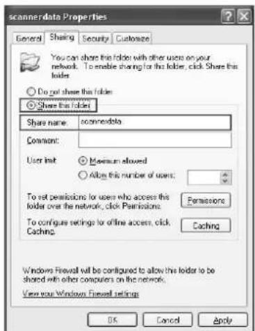
Create a shared folder to receive data in the destination computer. Share the folder by enabling folder sharing on a normal folder. The following example explains how to create a folder named "scannerdata" on drive C.
IMPORTANT: Log on to Windows with administrator privileges.
NOTE: The following description is one example of screenshots of Windows XP. The details differ depending on the type of operating system.
1 Create a folder named "scannerdata" on drive C.
2 Right-click the "scannerdata" folder and select Sharing and Security.... The scannerdata Properties dialog box appears.
3 Select Share this folder.
4 Click Permissions. The Permissions for scannerdata dialog box appears.
text_image
scannerdata Properties General Sharing Security Customize You can share this folder with other users on your network. To enable sharing for this folder, click Share this folder. Do not share this folder: Share this folder Share name: camncrdata Comment: User init: Minimum allowed Allow this number of users: To set permissions to users who access this folder over the network, click Permissions. Formations To configure settings for offline access, click Caching. Caching Windows Firewall will be configured to allow the folder to be shared with other computers on the network. View your Windows Firewall settings OK Cancel Apply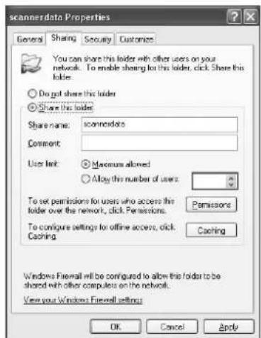
text_image
scannerdata Properties General Sharing Security Customize You can share this folder with other users on your network. To enable sharing for this folder, click Share this folder. Do not share this folder Share this folder Share name: scannerdata Comment: User Init: Maximum allowed Allow the number of users: To set permissions for users who access the folder over the network, click Permissions. To configure settings for offline access, click Caching Caching Windows Firewall will be configured to allow this folder to be shared with other computers on the network. View your Windows Firewall setting OK Cancel Apply5 Select the group or user to whom you want to grant permissions for the shared folder.
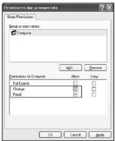
NOTE: The following example explains how to grant permissions for Everyone. Everyone is the setting that allows any users to share the folder over the network. Click Add to add groups or users that are selectable from the Group or user names. Use this setting if you want to limit the access to the shared folder to specific users or groups.
6 Click the checkbox under Allow for Change and Read, then click OK of the Permissions dialog box.
text_image
Permissions for scanner data Share Permissions Group or user names: Everyone Add Remove Permissions for Everyone Allow Only Full Control □ □ Change ☑ □ Read ☑ □ OK Cancel Apply7 Click the Security tab, then click Add.
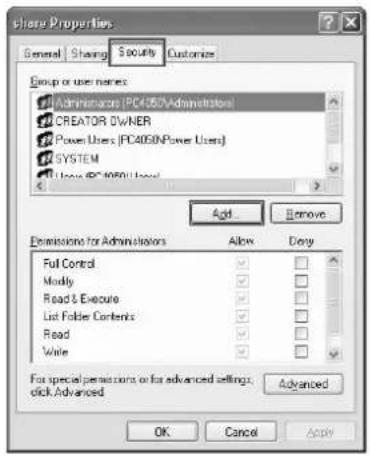
8 Add the user name displayed in the Group or user names. Click Add, then click Locations. Select the computer to which the shared folder was created (Example: PC4050) and then click OK.
9 Enter the user name added as a local user into the text box and click OK.
10 Select the added user, click the checkbox under Allow for Modify and Read, then click OK.
11 Click OK to close the Properties dialog box.
text_image
Share Properties General Sharing Security Customize Group or user names: Administrators (PC4050\Administrator) CREATOR OWNER Power Users (PC4050\Power Users) SYSTEM User (PC4050) User Add Remove Extensions for Administrators Allow Copy Full Control ✓ ✓ ✓ ✓ Modify ✓ ✓ ✓ ✓ Read & Execute ✓ ✓ ✓ ✓ List Folder Contents ✓ ✓ ✓ ✓ Read ✓ ✓ ✓ ✓ Write ✓ ✓ ✓ ✓ For special permissions or for advanced settings; click Advanced Advanced OK Cancel Apply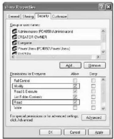
text_image
Share Properties General Sharing Security Customizer Group or user names: Administrators (PC4050\Administrator) CREATOR OWNER Everyone Power Users (PC4050\Power Users) EVEYEN Add Remove Exmissions for Everyone Full Control Modify Read & Execute List Folder Contents Read Write For special permissions or for advanced settings. click Advanced. Advanced OK Cancel ApplySpecifying Destination
Check the computer information required to enter on the touch panel when sending a file. The information you require to check using the computer is:
- Entry for Host Name
- Entry for Path
- Entry for Login User Name
Checking the Entry for Host Name
Check the name of the destination computer.
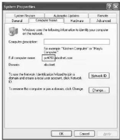
1 Right-click My Computer and select Properties. The System Properties dialog box appears.
2 Click the Computer Name tab to view the name of computer.
If the Computer Name tab contains Full computer name and Domain
The characters to the left of the first dot (.) in the Full computer name text box correspond to the entry for Host Name. (Example: pc4050)
If the Computer Name tab contains Full computer name and Workgroup
All characters in the Full computer name text box correspond to the entry for Host Name. (Example: PC4050)
text_image
System Properties System Restore Automatic Updates Remote General Computer Name Hardware Advanced Windows uses the following information to identify your computer on the network. Computer description: For example "Kitchen Computer" or "Mary's Computer" Full computer name: pc4050.abcdnet.com Domain: abcdnet To use the Network Identification Wizard to join a domain and create a local user account, click Network ID Network ID To rename this computer or join a domain, click Change Change... OK Cancel Apply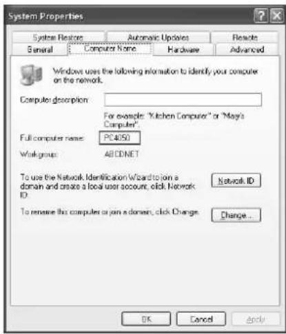
text_image
System Properties System Restore Automatic Updates Remote General Computer Name Hardware Advanced Windows uses the following information to identify your computer on the network. Computer description: For example: "Kitchen Computer" or "May's Computer". Full computer name: PC4050 Work group: ABCDNET To use the Network Identification Wizard to join a domain and create a local user account, click Network ID Network ID To rename this computer or join a domain, click Change... Change... OK Cancel ApplyChecking the Entry for Path
Check the share name for the shared folder to which data is sent.
1 Click Search in the Start menu. The Search Result page opens.
2 Search the destination computer to which the file is sent. In the Search Companion, click Printers, Computers, or people, and then click A computer on the network.
3 On the Computer name text box, type the name of computer (pc4050) you checked on page 24, and then click Search.
4 Double-click the name of computer (pc4050) displayed on the search results.
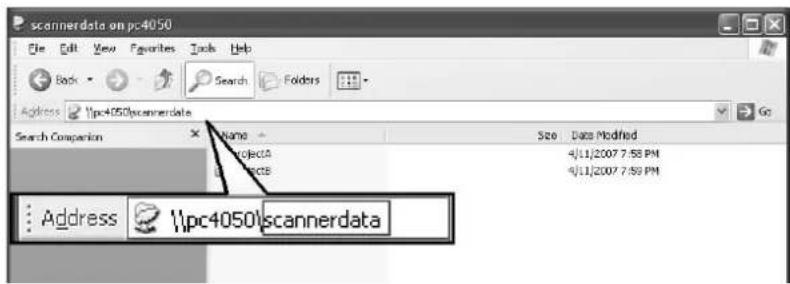
5 Double-click the "scannerdata" folder and check the full path displayed in the Address Bar. The characters to the right of the third backslash () correspond to the entry for Path.
(Example: scannerdata)
text_image
pc4050 pc4050\scannerdata Search Comparison Name ProjectA ProjectB Address pc4050\scannerdata Size Date Modified 4/11/2007 7:58 PM 4/11/2007 7:59 PMNOTE: You must use alphabets, numerals, and symbols (ASCII codes from 0 × 20 to 0 × 7F) only to enter Path.
You can specify a subfolder in the shared folder as the location where data is to be sent. In this case, the entry for Path is "share name\name of a folder in the shared folder". In the sample window above, "scannerdata\projectA" corresponds to Path.
Checking the Entry for PathName
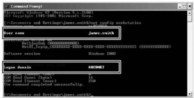
You can use the following steps to check the domain name and user name that must be entered in Login User Name.
1 Open the Command Prompt window. From the Start menu, select All Programs, Accessories and then Command Prompt.
2 At the Command Prompt, enter "net config workstation" and then press Enter.
text_image
Command Prompt Microsoft Windows XP [Version 5.1.2600] (C) Copyright 1985-2001: Microsoft Corp. C:\Documents and Settings\james.smith\net config workstation User name james.smith Logon domain ABCNET COM Open Timeout (msec) 4 COM Send Count (byte) 16 COM Send Timeout (msec) 250 The command completed successfully. C:\Documents and Settings\james.smith>.5 Installing Printer Driver
Ensure the machine is plugged in and connected to the PC before installing the printer driver from the CD-ROM.
Installing Printer Driver in Windows
If you are connecting this machine to a Windows PC, follow the next steps to install the printer driver. The example shows you how to connect your machine to a Windows Vista PC.
NOTE: In Windows Vista, Windows XP and Windows 2000, you must be logged on with administrator privileges.
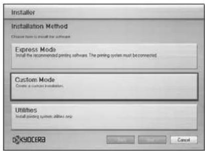
You can use either Express Mode or Custom Mode to install the software. Express Mode automatically detects connected machines and installs the required software. Use Custom Mode if you want to specify the printer port and select the software to be installed.
1 Turn on the computer and start up Windows.
If the Welcome to the Found New Hardware Wizard dialog box displays, select Cancel.
2 Insert the CD-ROM supplied with the machine into the optical drive of the PC. In Windows Vista, the user account management window appears. Click Allow.
The installation program launches.
NOTE: If the software install wizard does not launch automatically, open the CD-ROM window in Windows Explorer and double-click Setup.exe.
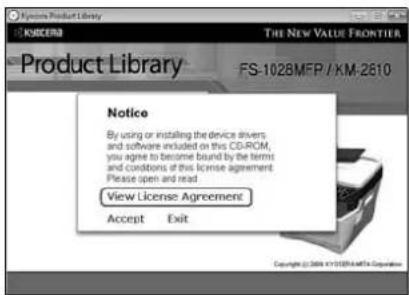
3 Click View License Agreement and read the License Agreement. Click Accept.
text_image
Product Library KSICEM THE NEW VALUE FRONTIER FS-1028MFP / KM-2610 Notice By using or installing the device drivers and software included on this CD-ROM, you agree to become bound by the terms and conditions of this license agreement. Please open and read View License Agreement Accept Exit Copyright © 2006 47105 (Kredite Co Corporation)4 Click Install Software. The software install wizard starts up.
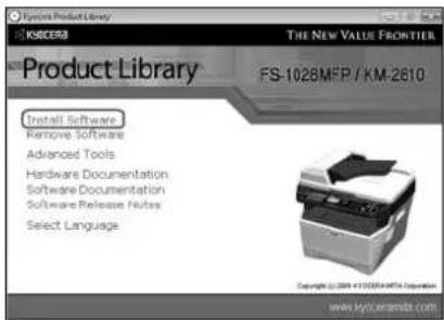
From this point, the procedure differs depending on your version of Windows and your connection method. Proceed to the correct procedure for your connection type.
- Express Mode
- Custom Mode
text_image
Product Library FS-1028MEP / KM-2610 Install Software Remove Software Advanced Tools Hardware Documentation Software Documentation Software Release Rules Select Language Copyright © 2016.41.2023/AMTA Corporation www.hyoceramta.comExpress Mode
In Express Mode, the installer automatically detects the machine when it is turned on. Use Express Mode for standard connection methods.
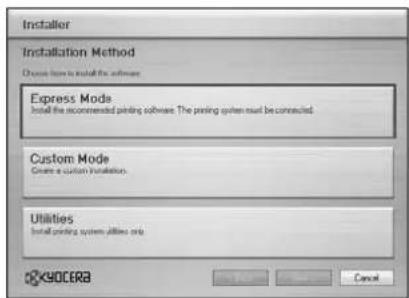
1 In the installation method selection window, select Express Mode. The print system detection window appears and the installer detects the connected machines. If the installer does not detect a print system, check that the print system is connected via USB or a network and that it is turned on. Then return to the print system detection window.
text_image
Installer Installation Method Choose how to install the software Express Mode Install the recommended printing software. The printing system must be connected. Custom Mode Create a custom installation. Utilities Install printing system utilities only OKOCERA CancelNOTE: While the information shown in Windows Vista and Windows XP installation dialog boxes differs slightly, the installation procedure is the same.
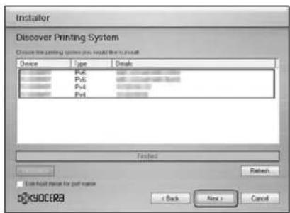
2 Select the print system to be installed and click Next.
text_image
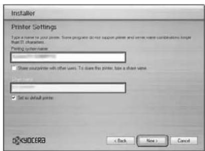
Installer Discover Printing System Choose the printing system you should like to install Device Type Details P6 P5 P4 P3 Tested OK Next > OK OK OK Cancel3 You can customize the print system name in the installation settings window. This will be the name displayed in the Printer window and in the printer lists displayed in applications. Specify whether to share the print system name or set the print system as an existing machine and then click Next.
text_image
Installer Printer Settings Type is not to print print. Some programs do not support print and serve more combinations longer than 10 characters. Printing system name: □ Share our printer with other users. To close this printer, then a share name □ Set as default print < Back Next > Cancel ©YOCERA3IMPORTANT: Step 3 only appears if the print system is connected via a network. It does not appear if the print system is connected via a USB.
4 A window appears in which you can check the settings. Check the settings carefully and then click Install.
NOTE: If the Windows security window appears, click Install this driver software anyway.
5 A message appears saying that the printer has been installed successfully. Click Finish to exit the printer installation wizard and return the CD-ROM main menu.
If the device setup dialog box appears after you click Finish, you can specify the settings for items such as optional features installed in the print system. You can also specify the device settings after you exit the installation. For details, refer to Device Settings in the printer driver operation manual on the CD-ROM.
This completes the printer driver installation procedure. Follow the on-screen instructions to restart the system, if required.
Custom Mode
Use Custom Mode if you want to specify the printer port and select the software to be installed. For example, if you do not want fonts installed on your computer to be replaced, select Custom Mode and deselect the Fonts checkbox in the utility tab.
NOTE: Install TWAIN driver or WIA driver on your computer in this mode.
1 Select Custom Mode.
text_image
Installer Installation Method Choose from to install the software Express Mode Install the recommended printing software. The printing system must be connected Custom Mode Create a custom installation. Utilities Install printing software, all other only OK90CERA Save Apply Cancel2 Following the instructions in the install wizard window, select the software packages to be installed and the specify the port, etc. For details, refer to Custom Installation in the printer driver operation manual on the CD-ROM.
Installing Printer Driver in Macintosh
1 Turn on the machine and the Macintosh.
2 Insert the included CD-ROM (Product Library) into the CD-ROM drive.
3 Double-click the CD-ROM icon.
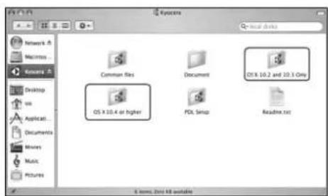
4 Double-click either OS X 10.2 and 10.3 Only or OS X 10.4 or higher depending on your Mac OS version.
text_image
Network A Macintosh Windows A Desktop VS Applications Documents Movies Music Pictures Systems Local disks Common files Document OS X 10.4 or higher PDL Setup OS X 10.2 and 10.3 Only Readme.txt 6 items, Zinc KB available5 Double-click Kyocera OS X vx.x.
text_image
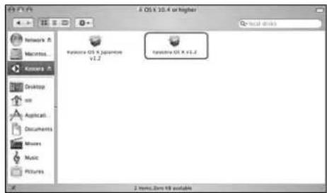
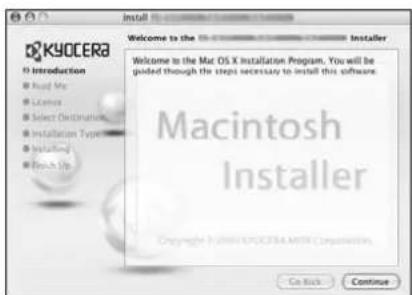
8 OS x 10.4 or higher Local disks Network A Macintosh... Kineset A Desktop on Applied... Documents Mines Music Pictures Kineset OS X (*.javikov) v1.2 Kineset OS X (*.v1.2) 2 Items: Zone 10 available6 The printer driver installation program starts up.
text_image
Welcome to the Mac OS X Installation Program, You will be guided though the steps necessary to install this software. Macintosh Installer Copyright © 2008 KYOCERA MDS Corporation Go Back Continue7 Choose Select Destination, Installation Type and then install the printer driver as directed by the instructions in the installation software.
In addition to Easy Install, the Installation Type options include Custom Install, which allows you to specify the components to be installed.
IMPORTANT: In the Authenticate screen, enter the name and password used to log in to the operating system. This completes the printer driver installation. Next, specify the print settings. If an IP or AppleTalk connection is used, the settings below are required. If a USB connection is used, the machine is automatically recognized and connected.
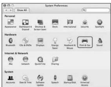
8 Open System Preferences and click Print & Fax.
text_image
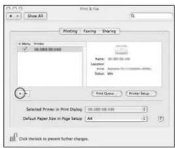
System Preferences 4 - In Show All Personal Appearance Dashboard & Exposure Desktop & Screen Saver Dock International Security Spotlight Hardware Bluetooth CDs & DVDs Displays Energy Saver Keyboard & Mouse Font & Fax Sound Internet & Network Mac Network Quick Time Sharing System Accounts Date & Time Software Update Speech Startup Disk Universal Access9 Click the plus symbol (+) to add the installed printer driver.
text_image
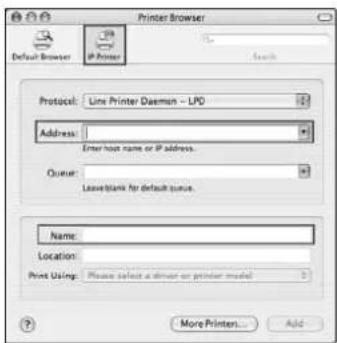
Print & Fax Show All Printing Fitting Sharing Name: 00.000.00.00 Location: Print: 00.000.00.00 Status: 00.000.00.00 Print Queue Printer Setup Selected Printer in Print Desktop: 00.000.00.00 Default Paper Size in Page Setup: AA Click thislock to prevent further changes.10 Click the IP icon for an IP connection or the AppleTalk icon for an AppleTalk connection and then enter the IP address and printer name.
text_image
Printer Browser Default Browser IP Printer Search Protocol: Line Printer Daemon - LPD Address: Enter host name or IP address. Output: Leave blank for default space. Name: Location: Print Using: Please select a driver or printer model More Printers... Add11 Select the installed printer driver and click Add.
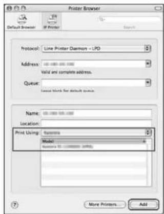
text_image
Printer Browser Default Browser If Printer Search Protocol: Line Printer Daemon - LPO Address: 00-000-00-000 Valid and complete address. Queue: Named blocks for default server Name: 00-000-00-000 Location: Print Using: Systems Model: Resources (12.13888888) (MPB) More Printers... Add12 Select the options available for the machine and click Continue.
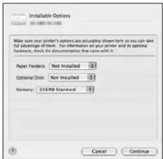
text_image
Installable Options Make sure your printer's options are accurately shown here so you can take full advantage of item. For information on your printer and its optional hardware, check the documentation that comes with it. Paper Feeders: Not Installed Optional Disk: Not Installed Memory: 256MB Standard Cancel Continue13 The selected machine is added. This completes the printer setup procedure.
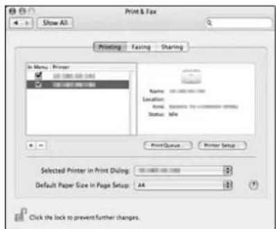
text_image
Print & Fax Show All Printing Faxing Sharing In Menu Printer Name: 100000000000000000000000000000000000000000000000000000000000000000000000000000000000 Location: Name: Dimension 14-25-25-25-25-25-25-25-25-25-25-25-25-25-25-25-25- Status: idle Print/Queue Printer Setup Selected Printer in Print Dialog: 3 Default Paper Size in Page Setup: A4 Click the lock to prevent further changes.Setting TWAIN Driver
Register this machine to the TWAIN Driver.
1 Select Start button of the Windows display, All Programs, Kyocera and then TWAIN Driver Setting.
NOTE: You can also add the machine to a PC when selecting Start of the Windows display, Control Panel and then Kyocera TWAIN.
2 Click Add.
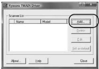
text_image
Kyocera TWAIN Driver Scanner List: Name Model Add... Delete Edit Set as default About... Help Close3 Enter the machine name in the Name field.
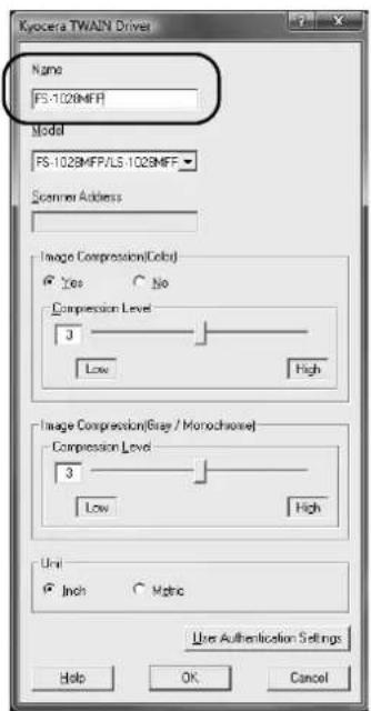
text_image
Kycera TWAIN Driver Name FS-1028MFF Model FS-1028MFF/LS-1028MFF Scanner Address Image Compression(Coles) Yes No Compression Level 3 Low High Image Compression(Gray / Monochrome) Compression Level 3 Low High Unit Inch Mplus Use Authentication Settings Help OK Cancel4 Click ▼ next to the Model field and select this machine from the list.
5 Enter the machine's IP address or host name in the Scanner Address.
NOTE: When the machine's IP address is unknown, contact Administrator.
6 Click User Authentication Settings. If user login administration is invalid, go to Step 8.
7 Select the checkbox beside Authentication, enter Login User Name (up to 64 characters) and Password (up to 64 characters) and then click OK.
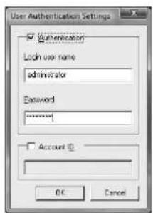
text_image
User Authentication Settings Authentication Login user name administrator Password ****** Account ID OK Cancel8 Click OK.
9 The machine is registered to the PC and the machine name and model name are displayed in the Scanner List field.
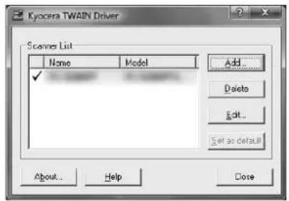
text_image
Kyocera TWAIN Driver Scaner List Name Model Add... Delete Edit... Set as default About... Help CloseNOTE: Click Delete to delete the added machine. Click Edit to change names.
Setting WIA Driver (Windows Vista™ and Windows® Server 2008)
Register this machine to the WIA Driver.
NOTE: The following is not necessary to register when using the machine possesses an IP address or host name that you have specified during installation of WIA Driver.
1 Select Start of the Windows display, Control Panel and then Scanners and Cameras.
2 Select the same name as this machine from WIA Drivers, and press the Properties.
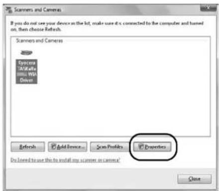
text_image
Scanners and Cameras If you do not see your device on the list, make sure it is connected to the computer and turned out, then choose Refresh. Scanners TASWALLE WBA Driver Refresh Add From... Scan Profiles Properties Do I need to use this to install any scanner or camera? CloseNOTE: If Windows Security and User Account Control are displayed, no trouble should be found with operation after installing the driver and software we have provided. Continue installation.
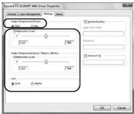
3 Click the Settings tab and select the Image Compression and the Compression Level. If user login administration is invalid, go to Step 5.
text_image
Kycocera FS-102BMFP WSA Driver Properties General Color Management Settings Output Image Compression (Color) ✓ No Compression Level 1 Low Hab Image Compression (Gray / Black & White) Compression Level 1 Low Hab Unit ✓ Inch ✓ Make Authentication Open User Name Password Account ID OK CancelNOTE: When the machine's IP address is unknown, contact Administrator.
4 Select the checkbox beside Authentication, enter Login User Name (up to 64 characters) and Password (up to 64 characters) and then click OK.
5 Click Close.
The machine is registered to the PC.