
WN-350R - Router AIRLIVE - Free user manual and instructions
Find the device manual for free WN-350R AIRLIVE in PDF.


| Product Type | Wireless Router |
| Brand | AirLive |
| Model | WN-350R |
| Dimensions (approx.) | 150 x 110 x 30 mm |
| Weight | 0.2 kg |
| Power Supply | 5V DC, 1A |
| Wireless Standard | IEEE 802.11b/g/n |
| Frequency Band | 2.4 GHz |
| Antenna | 2 external antennas (detachable) |
| LAN Ports | 4 x 10/100 Mbps |
| WAN Port | 1 x 10/100 Mbps |
| Security Features | WEP, WPA, WPA2, SPI Firewall, NAT |
| Management | Web-based GUI |
| Indicators | Power, WAN, LAN (4), WLAN |
| Operating Temperature | 0°C to 40°C |
| Certifications | CE, FCC |
| Cleaning Instructions | Wipe with a soft, dry cloth |
| Spare Parts Availability | Not user-serviceable; contact support |
Frequently Asked Questions - WN-350R AIRLIVE
User questions about WN-350R AIRLIVE
0 question about this device. Answer the ones you know or ask your own.
Ask a new question about this device
Download the instructions for your Router in PDF format for free! Find your manual WN-350R - AIRLIVE and take your electronic device back in hand. On this page are published all the documents necessary for the use of your device. WN-350R by AIRLIVE.
USER MANUAL WN-350R AIRLIVE
natural_image
Three smiling business professionals in a modern office setting (no visible text or symbols)Air Live®
Powered by OvisLink Corp.
Copyright
Copyright ©2010/2011 by this company. All rights reserved. No part of this publication may be reproduced, transmitted, transcribed, stored in a retrieval system, or translated into any language or computer language, in any form or by any means, electronic, mechanical, magnetic, optical, chemical, manual or otherwise, without the prior written permission of this company
This company makes no representations or warranties, either expressed or implied, with respect to the contents hereof and specifically disclaims any warranties, merchantability or fitness for any particular purpose. Any software described in this manual is sold or licensed "as is". Should the programs prove defective following their purchase, the buyer (and not this company, its distributor, or its dealer) assumes the entire cost of all necessary servicing, repair, and any incidental or consequential damages resulting from any defect in the software. Further, this company reserves the right to revise this publication and to make changes from time to time in the contents thereof without obligation to notify any person of such revision or changes.
Federal Communication Commission Interference Statement
FCC Part 15
This equipment has been tested and found to comply with the limits for a Class B digital device, pursuant to Part 15 of FCC Rules. These limits are designed to provide reasonable protection against harmful interference in a residential installation. This equipment generates, uses, and can radiate radio frequency energy and, if not installed and used in accordance with the instructions, may cause harmful interference to radio communications. However, there is no guarantee that interference will not occur in a particular installation. If this equipment does cause harmful interference to radio or television reception, which can be determined by turning the equipment off and on, the user is encouraged to try to correct the interference by one or more of the following measures:
- Reorient or relocate the receiving antenna.
- Increase the separation between the equipment and receiver.
- Connect the equipment into an outlet on a circuit different from that to which the receiver is connected.
- Consult the dealer or an experienced radio technician for help.
FCC Caution
This equipment must be installed and operated in accordance with provided instructions and a minimum 20 cm spacing must be provided between computer mounted antenna and person's body (excluding extremities of hands, wrist and feet) during wireless modes of operation.
This device complies with Part 15 of the FCC Rules. Operation is subject to the following two conditions: (1) this device may not cause harmful interference, and (2) this device must accept any interference received, including interference that may cause undesired operation.
Any changes or modifications not expressly approved by the party responsible for compliance could void the authority to operate equipment.
Federal Communication Commission (FCC) Radiation Exposure Statement
This equipment complies with FCC radiation exposure set forth for an uncontrolled environment. In order to avoid the possibility of exceeding the FCC radio frequency exposure limits, human proximity to the antenna shall not be less than 20cm (8 inches) during normal operation.
The antenna(s) used for this transmitter must not be co-located or operating in conjunction with any other antenna or transmitter.
The equipment version marketed in US is restricted to usage of the channels 1-11 only.
R&TTE Compliance Statement
This equipment complies with all the requirements of DIRECTIVE 1999/5/EC OF THE EUROPEAN PARLIAMENT AND THE COUNCIL of March 9, 1999 on radio equipment and telecommunication terminal Equipment and the mutual recognition of their conformity (R&TTE).
The R&TTE Directive repeals and replaces in the directive 98/13/EEC (Telecommunications Terminal Equipment and Satellite Earth Station Equipment) As of April 8, 2000.
Safety
This equipment is designed with the utmost care for the safety of those who install and use it. However, special attention must be paid to the dangers of electric shock and static electricity when working with electrical equipment. All guidelines of this and of the computer manufacture must therefore be allowed at all times to ensure the safe use of the equipment.
EU Countries Intended for Use
The ETSI version of this device is intended for home and office use in Austria, Belgium, Denmark, Finland, France, Germany, Greece, Ireland, Italy, Luxembourg, the Netherlands, Portugal, Spain, Sweden, and the United Kingdom.
The ETSI version of this device is also authorized for use in EFTA member states: Iceland, Liechtenstein, Norway, and Switzerland.
EU Countries Not intended for use
None.

Bluetooth®
© 2009 OvisLink Corporation, All Rights Reserved
Table of Contents
1. Product Information .... 1
1.1. Introduction and Safety Information .... 1
1.2. Safety Information....3
1.3. System Requirements......4
1.4. Package Contents......4
1.5. Familiar with Your New Wireless Broadband Router......5
2. System and Network Setup....7
2.1. Build Network Connection....7
2.2. Connecting to Wireless Broadband Router by Web Browser.....10
2.2.1. Windows 95/98/Me IP Address Setup .... 11
2.2.2. Windows 2000 IP Address Setup ....13
2.2.3. Windows XP IP Address Setup 15
2.2.4. Windows Vista IP Address Setup 17
2.2.5. Router IP Address Lookup....19
2.3. Using 'Quick Setup'......23
2.3.1. Setup Procedure for 'Cable Modem' 27
2.3.2. Setup Procedure for 'Fixed-IP xDSL'.....28
2.3.3. Setup Procedure for 'PPPoE xDSL'.....29
2.3.4. Setup Procedure for 'PPTP xDSL' 31
2.3.5. Setup Procedure for 'L2TP xDSL'....33
2.3.6. Setup Procedure for 'Telstra Big Pond'......36
2.4. Basic Setup....38
2.4.1. Time Zone and Time Auto-synchronization .....39
2.4.2. Change Management Password ....40
2.4.3. Remote Management....43
2.5. Setup Internet Connection (WAN Setup) 46
2.5.1. Setup Procedure for 'Dynamic IP' 48
2.5.2. Setup Procedure for 'Static IP' 50
WN-350R User's Manual
2.5.3. Setup Procedure for 'PPPoE' 52
2.5.4. Setup Procedure for 'PPTP' 54
2.5.5. Setup Procedure for 'L2TP' 57
2.5.6. Setup Procedure for 'Telstra Big Pond'......59
2.5.7. Setup Procedure for 'DNS' 60
2.5.8. Setup Procedure for 'DDNS'......62
2.5.9. Setup Procedure for 'WISP' 64
2.6. Wired LAN Configurations....68
2.6.1. LAN IP Section....70
2.6.2. DHCP Server....71
2.6.3. Static DHCP Leases Table 72
2.7. Wireless LAN Configurations ..... 75
2.7.1. Basic Wireless Settings....77
2.7.2. Advanced Wireless Settings....89
2.7.3. Wireless Security....92
2.7.4. Wireless Access Control....99
2.7.5. Wi-Fi Protected Setup (WPS)....102
2.7.6. Security Tips for Wireless Network....105
3. Advanced Functions ...... 106
3.1. Configuration Utility....106
3.1.1. Basic QoS Settings ..... 107
3.1.2. Add a New QoS Rule 110
3.2. Network Address Translation (NAT) 113
3.2.1. Basic NAT Settings (Enable or Disable NAT Function).... 113
3.2.2. Port Forwarding.... 115
3.2.3. Virtual Server....118
3.2.4. Port Mapping for Special Applications 121
3.2.5. UPnP Setting....124
3.2.6. ALG Settings 125
3.3. Firewall....128
3.3.1. Access Control 129
3.3.2. URL Blocking....135
3.3.3. DoS Attack Prevention 137
3.3.4. Demilitarized Zone (DMZ) 142
3.4. System Status....146
3.4.1. System Information and Firmware Version....146
3.4.2. Internet Connection Status 147
3.4.3. Device Status 148
3.4.4. System Log 149
3.4.5. Security Log 150
3.4.6. Active DHCP Client List....151
3.4.7. Statistics 152
3.5. Configuration Backup and Restore 153
3.6. Firmware Upgrade 155
3.7. System Reset....157
4. Appendix 158
4.1. Hardware Specification .... 158
4.2. Troubleshooting 159
4.3. Glossary....163
1 Product Information
natural_image
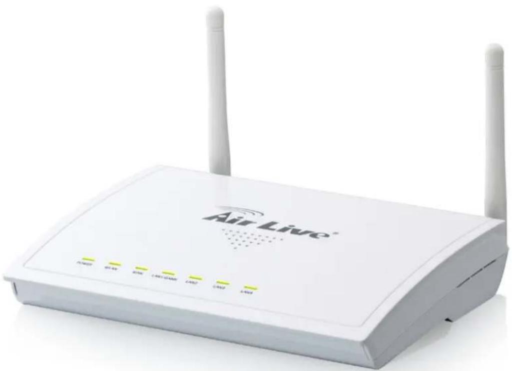
White Air Live wireless router with two antennas and control buttons (no visible text or symbols on body)1.1. Introduction and Safety Information
Thank you for purchasing this wireless broadband router! This high cost-efficiency router is the best choice for Small office / Home office users, all computers and network devices can share a single xDSL / cable modem internet connection at high speed. Easy install procedures allows any computer users to setup a network environment in very short time - within minutes, even inexperienced. When the number of your computers and network-enabled devices grow, you can also expand the number of network slot by simple attach a hub or switch, to extend the scope of your network!
All computers and IEEE 802.11b/g/n wireless-enabled network devices (including PDA, cellular phone, game console, and more!) can connect to this wireless router without additional cabling. With a compatible wireless card installed in your PC, you can transfer file for up to 300Mbps (transfer data rate).
Other features of this router including:
• High Internet Access throughput
- Allow multiple users to share a single Internet line
• Supports up to 253 users
- Share a single Cable or xDSL internet connection
- Access private LAN servers from the internet
- Four wired LAN ports (10/100M) and one WAN port (10/100M)
• Work with IEEE 802.11b/g/n wireless LAN devices
- Support DHCP (Server/Client) for easy IP-address setup
- Support multiple wireless modes like: AP, Station-Infrastructure, Wireless Bridge and Universal Repeater.
• Support WISP mode for accessing Internet through wireless network
- Advanced network and security features like: Special Applications, QoS, DMZ, Virtual Servers, Access Control, Firewall.
- Allow you to monitor the router's status like: DHCP Client Log, System Log, Security Log and Device/Connection Status
- Easy to use Web-based GUI for network configuration and management purposes
- Remote management function allows configuration and upgrades from a remote computer (over the Internet)
• Auto MDI / MDI-X function for all wired Ethernet ports.
1.2. Safety Information
In order to keep the safety of users and your properties, please follow the following safety instructions:
-
This router is designed for indoor use only; DO NOT place this router outdoor.
-
DO NOT put this router at or near hot or humid places, like kitchen or bathroom. Also, do not left this router in the car in summer.
-
DO NOT pull any connected cable with force; disconnect it from the router first.
-
If you want to place this router at high places or hang on the wall, please make sure the router is firmly secured. Falling from high places would damage the router and its accessories, and warranty will be void.
-
Accessories of this router, like antenna and power supply, are danger to small children under 3 years old. They may put the small parts in their nose or month and it could cause serious damage to them. KEEP THIS ROUTER OUT THE REACH OF CHILDREN!
-
The router will become hot when being used for long time (This is normal and is not a malfunction). DO NOT put this router on paper, cloth, or other flammable materials.
-
There's no user-serviceable part inside the router. If you found that the router is not working properly, please contact your dealer of purchase and ask for help. DO NOT disassemble the router, warranty will be void.
-
If the router falls into water when it's powered, DO NOT use your hand to pick it up. Switch the electrical power off before you do anything, or contact an experienced technician for help.
-
If you smell something strange, or even see some smoke coming out from the router or power supply, remove the power supply or switch the electrical power off immediately, and call dealer of purchase for help.
1.3. System Requirements
- Internet connection, provided by xDSL or cable modem with a RJ-45 Ethernet port.
• Computer or network devices with wired or wireless network interface card.
• Web browser (Microsoft Internet Explorer 4.0 or above, Netscape Navigator 4.7 or above, Opera web browser, or Safari web browser). - An available AC power socket (100 – 240V, 50/60Hz)
1.4. Package Contents
Before you starting to use this router, please check if there's anything missing in the package, and contact your dealer of purchase to claim for missing items:
- Broadband router (main body, 1 pcs)
- Quick installation guide and User manual CDROM (1 pcs)
• A/C power adapter (1 pcs)
1.5. Familiar with Your New Wireless Broadband Router
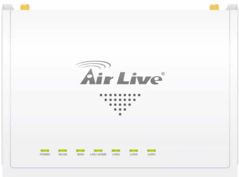
- Front Panel
text_image
Air Live® POWER WLAN WAN LAN1/GAME LAN2 LAN3 LAN4| LED Name Light Status Description | |
| PWR On Router is switched | on and correctly powered. |
| WLAN | On Wireless WPS function is enabled. |
| Off Wireless network is switched off. | |
| Flashing Wireless LAN activity (transferring or receiving data). | |
| WAN | On WAN port is connected. |
| Off WAN port is not connected. | |
| LNK/ACT | Flashing WAN activity (transferring or receiving data). |
| LAN 1-4 | On LAN port is connected. |
| Off LAN port is not connected. | |
| LNK/ACT | Flashing LAN activity (transferring or receiving data). |
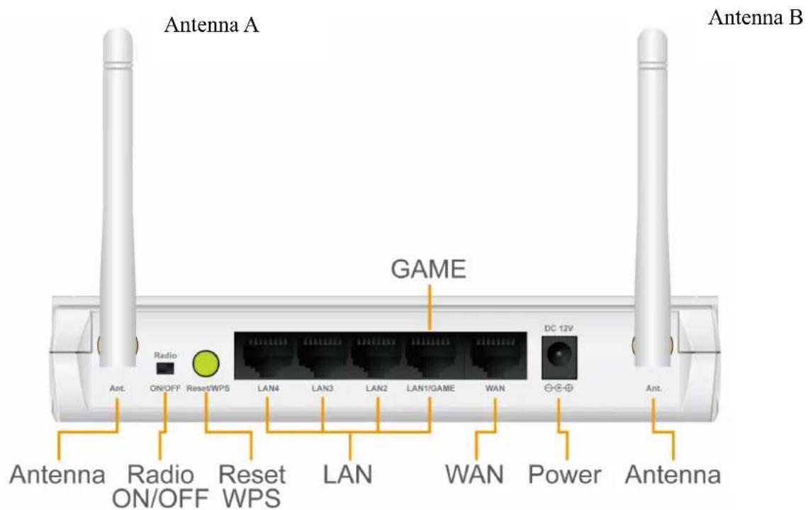
- Back Panel
text_image
Antenna A Radio ON/OFF Reset/WPS LAN4 LAN3 LAN2 LAN1/GAME WAN GAME DC 12V Antenna Radio ON/OFF Reset WPS LAN WAN Power Antenna| Item Name Description | |
| Antenna A/B These antennas are 3dBi dipole antennas. | |
| Radio ON/OFF | Switch the button to activate or deactivate the wireless functions. |
| Reset / WPS | Reset the router to factory default settings (clear all settings) or start WPS function. Press this button and hold for 10 seconds to restore all settings to factory defaults, and press this button for less than 5 seconds to start WPS function. |
| 1 - 4 Local Area | Network (LAN) ports 1 to 4. |
| WAN Wide Area | Network (WAN / Internet) port. |
| Power Power | connector, connects to A/C power adapter. |
2
System and Network Setup
2.1. Build Network Connection
Please follow the following instruction to build the network connection between your new WIRELESS router and your computers, network devices:
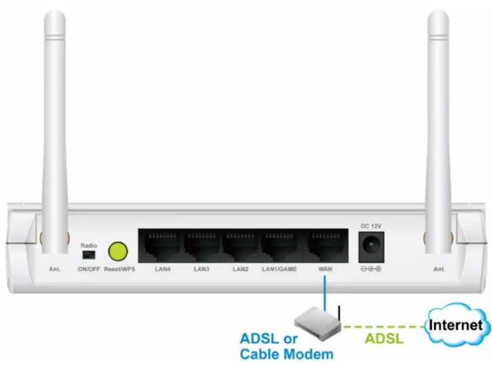
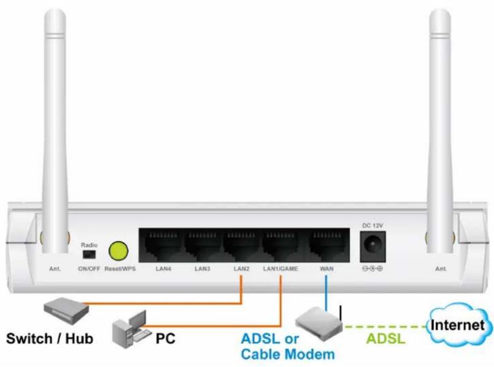
- Connect your xDSL / cable modem to the WAN port of router by Ethernet cable.
text_image
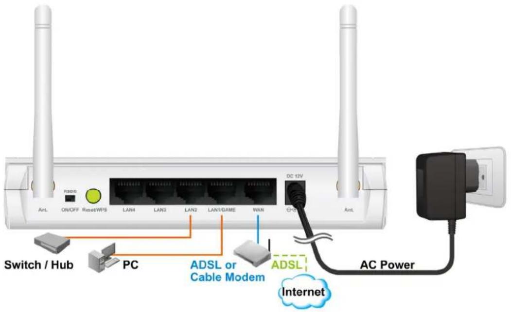
Radio ON/OFF Reset/WPS LAN4 LAN3 LAN2 LAN1/GAME WAN DC 12V Ant. Ant. ADSL or Cable Modem ADSL Internet- Connect all your computers, network devices (network-enabled consumer devices other than computers, like game console, or switch / hub) to the LAN port of the router.
text_image
Radio ON/OFF Reset/WPS LAN4 LAN3 LAN2 LAN1/GAME WAN DC 12V Switch / Hub PC ADSL or Cable Modem ADSL Internet- Connect the A/C power adapter to the wall socket, and then connect it to the 'Power' socket of the router.
text_image
Switch / Hub PC ADSL or Cable Modem ADSL Internet AC Power DC 12V R300G ON/OFF Reset/WPS LAN4 LAN3 LAN2 LAN1/GAME WAN O-S Ant- Please check all LEDs on the front panel. 'PWR' LED should be steadily on, WAN and LAN LEDs should be on if the computer / network device connected to the respective port of the router is powered on and correctly connected. If PWD LED is not on, or any LED you expected is not on, please recheck the cabling, or jump to '4.2. Troubleshooting' for possible reasons and solution.
2.2. Connecting to Wireless Broadband Router by Web Browser
After the network connection is built, the next step you should do is setup the router with proper network parameters, so it can work properly in your network environment.
Before you can connect to the router and start configuration procedures, your computer must be able to get an IP address automatically (use dynamic IP address). If it's set to use static IP address, or you're unsure, please follow the following instructions to configure your computer to use dynamic IP address:
If the operating system of your computer is....
Windows 95/98/Me - please go to section 2.2.1.
Windows 2000 - please go to section 2.2.2.
Windows XP - please go to section 2.2.3.
Windows Vista - please go to section 2.2.4.
2.2.1. Windows 95/98/Me IP Address Setup
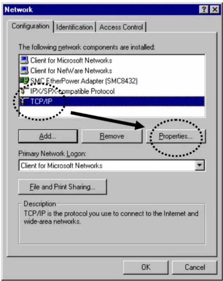
- Click 'Start' button (it should be located at lower-left corner of your computer), then click control panel. Double-click Network icon, and Network window will appear. Select 'TCP/IP', then click 'Properties'.
text_image
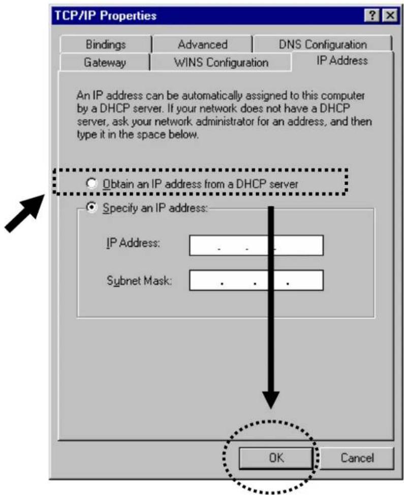
Network Configuration | Identification | Access Control | The following network components are installed: Client for Microsoft Networks Client for NetWare Networks SMC EtherPower Adapter (SMC8432) IPX/SPX-compatible Protocol TCP/IP Add... Remove Properties... Primary Network Logon: Client for Microsoft Networks File and Print Sharing... Description TCP/IP is the protocol you use to connect to the Internet and wide-area networks. OK Cancel- Select 'Obtain an IP address from a DHCP server' and then click 'OK'.
text_image
TCP/IP Properties Bindings Advanced DNS Configuration Gateway WINS Configuration IP Address An IP address can be automatically assigned to this computer by a DHCP server. If your network does not have a DHCP server, ask your network administrator for an address, and then type it in the space below. Obtain an IP address from a DHCP server Specify an IP address: IP Address: .. Subnet Mask: .. OK Cancel2.2.2. Windows 2000 IP Address Setup
- Click 'Start' button (it should be located at lower-left corner of your computer), then click control panel. Double-click Network and Dial-up Connections icon; click Local Area Connection, and Local Area Connection Properties window will appear. Select 'Internet Protocol (TCP/IP)' and then click 'Properties'
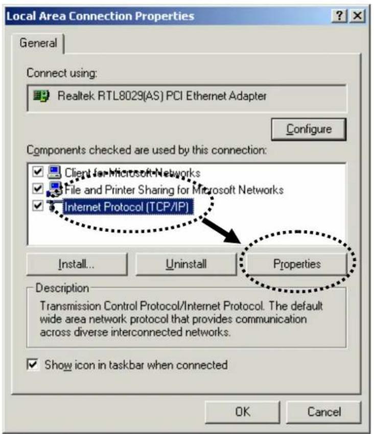
text_image
Local Area Connection Properties General Connect using: Realtek RTL8029(AS) PCI Ethernet Adapter Configure Components checked are used by this connection: Client for Microsoft Networks File and Printer Sharing for Microsoft Networks Internet Protocol (TCP/IP) Install... Uninstall Properties Description Transmission Control Protocol/Internet Protocol. The default wide area network protocol that provides communication across diverse interconnected networks. Show icon in taskbar when connected OK Cancel- Select 'Obtain an IP address automatically' and 'Obtain DNS server address automatically', then click 'OK'.
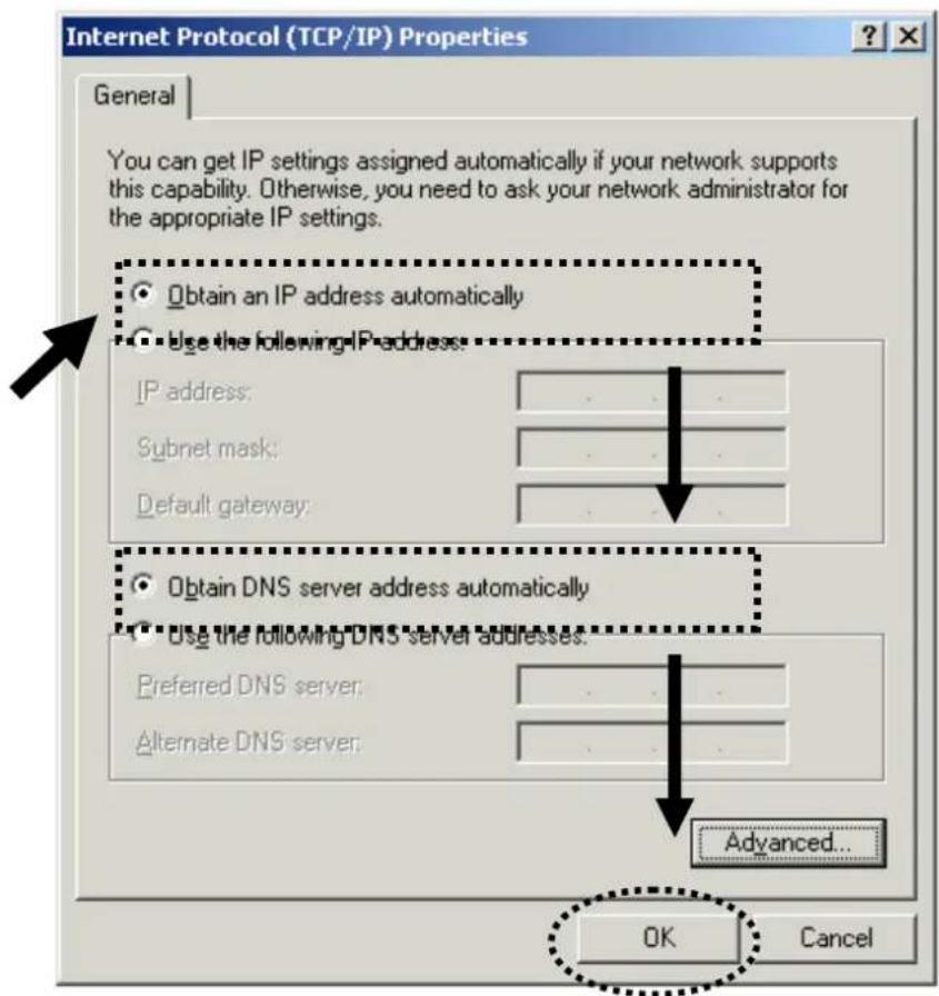
text_image
Internet Protocol (TCP/IP) Properties General You can get IP settings assigned automatically if your network supports this capability. Otherwise, you need to ask your network administrator for the appropriate IP settings. Obtain an IP address automatically Use the following IP address: IP address: Subnet mask: Default gateway: Obtain DNS server address automatically Use the following DNS server addresses: Preferred DNS server: Alternate DNS server: Advanced... OK Cancel2.2.3. Windows XP IP Address Setup
- Click 'Start' button (it should be located at lower-left corner of your computer), then click control panel. Double-click Network and Internet Connections icon, click Network Connections, then double-click Local Area Connection, Local Area Connection Status window will appear, and then click 'Properties'

text_image
Local Area Connection Properties General Authentication Advanced Connect using: AMD PCNET Family PCI Ethernet Ad Configure... This connection uses the following items: ✓ Client for Microsoft Networks ✓ File and Printer Sharing for Microsoft Networks ✓ DoS Packet Scheduler ✓ Internet Protocol (TCP/IP) Install... Uninstall Properties Description Transmission Control Protocol/Internet Protocol. The default wide area network protocol that provides communication across diverse interconnected networks. Show icon in notification area when connected ✓ Notify me when this connection has limited or no connectivity OK Cancel- Select 'Obtain an IP address automatically' and 'Obtain DNS server address automatically', then click 'OK'.
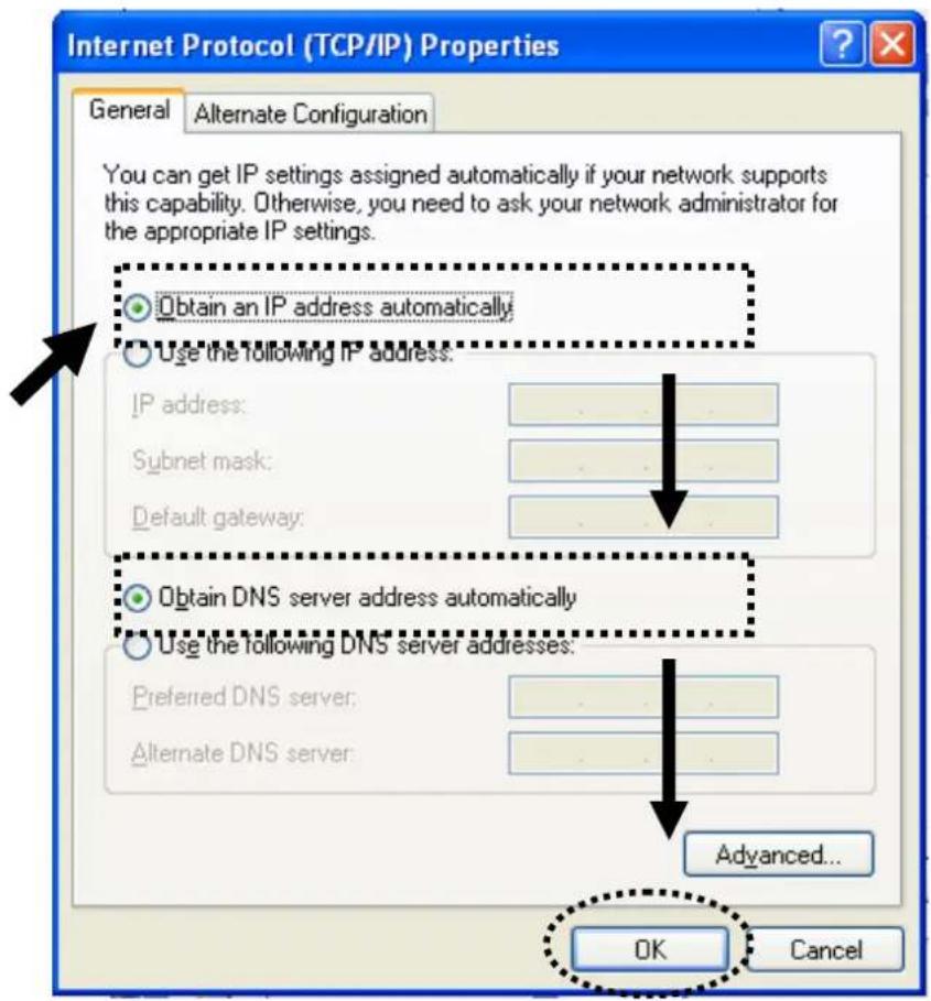
text_image
Internet Protocol (TCP/IP) Properties General Alternate Configuration You can get IP settings assigned automatically if your network supports this capability. Otherwise, you need to ask your network administrator for the appropriate IP settings. Obtain an IP address automatically Use the following IP address. IP address: Subnet mask: Default gateway: Obtain DNS server address automatically Use the following DNS server addresses: Preferred DNS server: Alternate DNS server: Advanced... OK Cancel2.2.4. Windows Vista IP Address Setup
- Click 'Start' button (it should be located at lower-left corner of your computer), then click control panel. Click View Network Status and Tasks, and then click Manage Network Connections. Right-click Local Area Network, then select 'Properties'. Local Area Connection Properties window will appear, select 'Internet Protocol Version 4 (TCP / IPv4), and then click 'Properties'
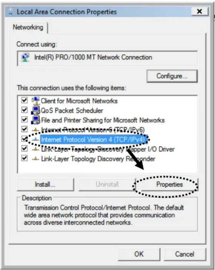
text_image
Local Area Connection Properties Networking Connect using: Intel(R) PRO/1000 MT Network Connection Configure... This connection uses the following items: ✓ Client for Microsoft Networks ✓ QoS Packet Scheduler ✓ File and Printer Sharing for Microsoft Networks ✓ Internet Protocol Version 6 (TCP/IPv6) ✓ Internet Protocol Version 4 (TCP/IPv4) ✓ Link-Layer Topology Discovery Mapper I/O Driver ✓ Link-Layer Topology Discovery Remponder Install... Uninstall Properties Description Transmission Control Protocol/Internet Protocol. The default wide area network protocol that provides communication across diverse interconnected networks. OK Cancel- Select 'Obtain an IP address automatically' and 'Obtain DNS server address automatically', then click 'OK'.

text_image
Internet Protocol Version 4 (TCP/IPv4) Properties General | Alternate Configuration | You can get IP settings assigned automatically if your network supports this capability. Otherwise, you need to ask your network administrator for the appropriate IP settings. Obtain an IP address automatically Use the following IP address: IP address: Subnet mask: Default gateway: Obtain DNS server address automatically Use the following DNS server addresses: Preferred DNS server: Alternate DNS server: Advanced... OK Cancel2.2.5. Router IP Address Lookup
After the IP address setup is complete, please click 'start' -> 'run' at the bottom-lower corner of your desktop.
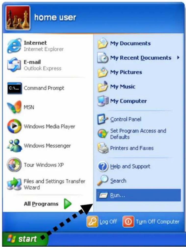
text_image
home user Internet Internet Explorer E-mail Outlook Express Command Prompt MSN Windows Media Player Windows Messenger Tour Windows XP Files and Settings Transfer Wizard All Programs My Documents My Recent Documents My Pictures My Music My Computer Control Panel Set Program Access and Defaults Printers and Faxes Help and Support Search Run... Log Off Turn Off Computer startInput 'cmd', and then click 'OK'
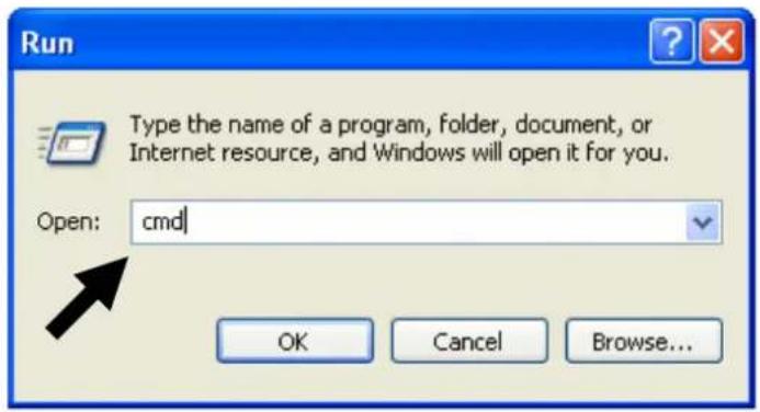
text_image
Run Type the name of a program, folder, document, or Internet resource, and Windows will open it for you. Open: cmd OK Cancel Browse...Input 'ipconfig', then press 'Enter' key. Please check the IP address followed by 'Default Gateway' (In this example, the IP address of router is 192.168.1.254, please note that this value may be different.)
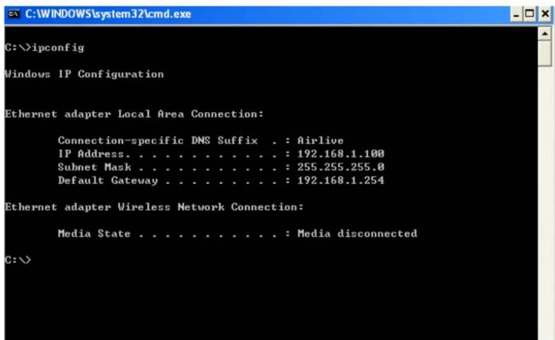
text_image
C:\>ipconfig Windows IP Configuration Ethernet adapter Local Area Connection: Connection-specific DNS Suffix . : Airlive IP Address. . . . . . . . . . . . : 192.168.1.100 Subnet Mask . . . . . . . . . . . . : 255.255.255.0 Default Gateway . . . . . . . . . . : 192.168.1.254 Ethernet adapter Wireless Network Connection: Media State . . . . . . . . . . . : Media disconnected C:\>NOTE: If the IP address of Gateway is not displayed, or the address followed by 'IP Address' begins with '169', please recheck network connection between your computer and router, and / or go to the beginning of this chapter, to recheck every step of network setup procedure.
Connect the router's management interface by web browser
After your computer obtained an IP address from router, please start your web browser, and input the IP address of router in address bar. The following message should be shown:
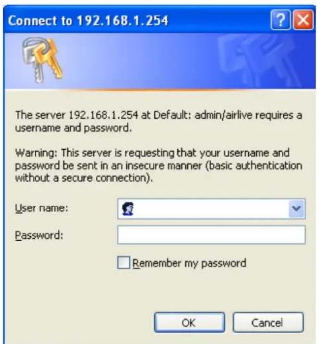
text_image
Connect to 192.168.1.254 The server 192.168.1.254 at Default: admin/airlive requires a username and password. Warning: This server is requesting that your username and password be sent in an insecure manner (basic authentication without a secure connection). User name: Password: Remember my password OK CancelPlease input user name and password in the field respectively, default user name is 'admin', and default password is 'airlive', then press 'OK' button, and you can see the web management interface of this router:
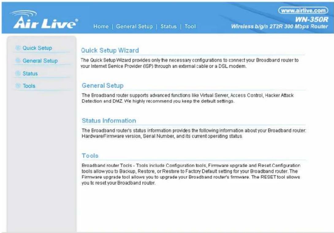
text_image
www.airlive.com WN-350R Home | General Setup | Status | Tool Wireless b/g/n 2T2R 300 Mbps Router Quick Setup Wizard The Quick Setup Wizard provides only the necessary configurations to connect your Broadband router to your Internet Service Provider (ISP) through an external cable or a DSL modem. General Setup The Broadband router supports advanced functions like Virtual Server, Access Control, Hacker Attack Detection and DMZ. We highly recommend you keep the default settings. Status Information The Broadband router's status information provides the following information about your Broadband router: Hardware/Firmware version, Serial Number, and its current operating status. Tools Broadband router Tools - Tools include Configuration tools, Firmware upgrade and Reset Configuration tools allow you to Backup, Restore, or Restore to Factory Default setting for your Broadband router. The Firmware upgrade tool allows you to upgrade your Broadband router's firmware. The RESET tool allows you to reset your Broadband router.NOTE: If you can't see the web management interface, and you're being prompted to input user name and password again, it means you didn't input username and password correctly. Please retype user name and password again. If you're certain about the user name and password you type are correct, please go to '4-2 Troubleshooting' to perform a factory reset, to set the password back to default value.
TIP: This page shows the four major setting categories: QuickSetup, General Setup, Status, and Tools. You can find the shortcut which leads to these setting categories at the upper-right corner of every page, and you can jump to another category directly by clicking the link, and don't have to go back to the first page.
2.3. Using 'Quick Setup'
This router provides a 'Quick Setup' procedure, which will help you to complete all required settings you need to access the Internet in very short time. Please follow the following instructions to complete the 'Quick Setup':
Please go to QuickSetup menu by clicking 'QuickSetup' button.
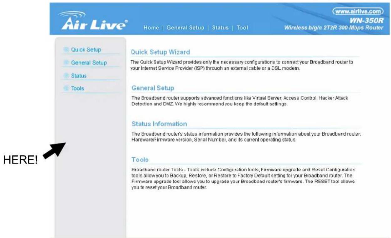
text_image
www.airlive.com WN-350R Wireless b/g/n 2T2R 300 Mbps Router Home | General Setup | Status | Tool Quick Setup Wizard The Quick Setup Wizard provides only the necessary configurations to connect your Broadband router to your Internet Service Provider (ISP) through an external cable or a DSL modem. General Setup The Broadband router supports advanced functions like Virtual Server, Access Control, Hacker Attack Detection and DMZ. We highly recommend you keep the default settings. Status Information The Broadband router's status information provides the following information about your Broadband router: Hardware/Firmware version, Serial Number, and its current operating status. Tools Broadband router Tools - Tools include Configuration tools, Firmware upgrade and Reset Configuration tools allow you to Backup, Restore, or Restore to Factory Default setting for your Broadband router. The Firmware upgrade tool allows you to upgrade your Broadband router's firmware. The RESET tool allows you to reset your Broadband router. HERE!And the following message will be displayed:
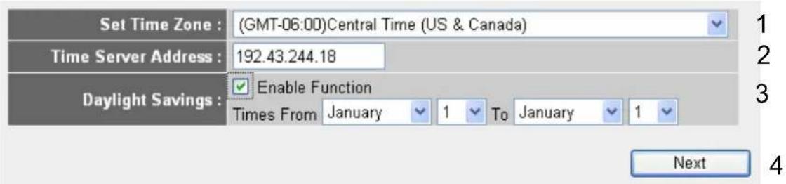
1. Set Time Zone
text_image
Set Time Zone : (GMT-06:00)Central Time (US & Canada) Time Server Address : 192.43.244.18 Daylight Savings : Enable Function Times From January 1 To January 1 NextHere are descriptions of every setup items:
Set Time Please press button, a drop-down list
Zone (1): will be shown, and you can choose a time zone of the location you live.
Time Server Input the IP address / host name of time server
Address (2): here
Daylight If the country you live uses daylight saving,
Savings(3): please check 'Enable Function' box, and choose the duration of daylight saving.
After you finish with all settings, please click 'Apply' (4) button.
NOTE: There are several time servers available on internet:
129.6.15.28 (time-a.nist.gov)
132.163.4.101 (time-a.timefreq.bldrdoc.gov)
131.107.1.10 (time-nw.nist.gov)
If you found that the time of router is incorrect, try another time server.
2. Broadband Type
Broadband Type
Specify the WAN connection type required by your Internet Service Provider. Specify a Cable modem, Fixed-IP xDSL, PPPoE xDSL or PPTP xDSL connection.
+ Cable Modem
A connection through a cable modem requires minimal configuration. When you set up an account with your Cable provider, the Cable provider and your Broadband router will automatically establish a connection, so you probably do not need to enter anything more.
+ Fixed-IP xDSL
Some xDSL Internet Service Providers may assign a Fixed IP Address for your Broadband router. If you have been provided with this information, choose this option and enter the assigned IP Address, Subnet Mask, Gateway IP Address and DNS IP Address for your Broadband router.
+ PPPoE xDSL
If you connect to the Internet using an xDSL Modem and your ISP has provided you with a Password and a Service Name, then your ISP uses PPPoE to establish a connection. You must choose this option and enter the required information.
+ PPTP xDSL
If you connect to the Internet using an xDSL Modem and your ISP has provided you with a Password, Local IP Address, Remote IP Address and a Connection ID, then your ISP uses PPTP to establish a connection. You must choose this option and enter the required information.
+ L2TP xDSL
Layer Two Tunneling Protocol is a common connection method used in xDSL connections.
+ Telstra Big Pond
If your Internet service is provided by Telstra Big Pond in Australia, you will need to enter your information below. This information is provided by Teistra BigPond.
Please choose the broadband (Internet connection) type you're using in this page. There are six types of Internet connection, they are:
Cable Modem - Please go to section 2.3.1.
Fixed-IP xDSL - Please go to section 2.3.2.
PPPoE xDSL - Please go to section 2.3.3.
PPTP xDSL - Please go to section 2.3.4.
L2TP xDSL - Please go to section 2.3.5.
Telstra Big Pond - Please go to section 2.3.6.
If you're not sure, please contact your Internet service provider. A wrong Internet connection type will cause connection problem, and you will not be able to connect to internet.
If you want to go back to previous step, please press 'Back' button on the bottom of this page.
NOTE: Some service providers use ‘DHCP’ (Dynamic Host Configuration Protocol) to assign IP address to you. In this case, you can choose ‘Cable Modem’ as Internet connection type, even you’re using another connection type, like xDSL. Also, some cable modem uses PPPoE, so you can choose ‘PPPoE xDSL’ for such cable modem connection, even you’re using a cable modem.
2.3.1. Setup Procedure for 'Cable Modem'
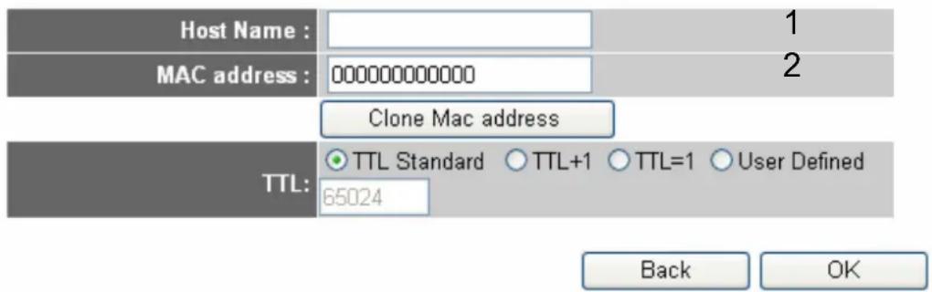
Cable Modem
text_image
Host Name : MAC address : 000000000000 Clone Mac address TTL: TTL Standard ○ TTL+1 ○ TTL=1 ○ User Defined 65024 Back OK3
Here are descriptions of every setup items:
Host Name (1): Please input the host name of your computer, this is optional, and only required if your service provider asks you to do so.
MAC address (2): Please input MAC address of your computer here, if your service provider only permits computer with certain MAC address to access internet. If you're using the computer which used to connect to Internet via cable modem, you can simply press 'Clone Mac address' button to fill the MAC address field with the MAC address of your computer.
After you finish with all settings, please click 'OK' (3) button; if you want to go back to previous menu, click 'Back'.
2.3.2. Setup Procedure for 'Fixed-IP xDSL'
Fixed-IP xDSL
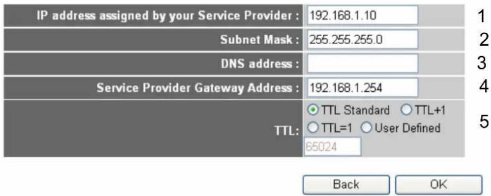
Enter the IP Address, Subnet Mask, Gateway IP Address and DNS IP Address provided to you by your ISP in the appropriate fields.
text_image
IP address assigned by your Service Provider : 192.168.1.10 Subnet Mask : 255.255.255.0 DNS address : Service Provider Gateway Address : 192.168.1.254 TTL: ○ TTL Standard ○ TTL+1 ○ TTL=1 ○ User Defined 65024 Back OKHere are descriptions of every setup items:
IP Address (1): Please input IP address assigned by your service provider.
Subnet Mask (2): Please input subnet mask assigned by your service provider
DNS address (3): Please input the IP address of DNS server provided by your service provider.
Service Provider Please input the IP address of DNS server
Gateway Address (4): provided by your service provider.
You must use the addresses provided by your Internet service provider, wrong setting value will cause connection problem.
When you finish with all settings, press 'OK' (5); if you want to go back to previous menu, click 'Back'.
NOTE: You can choose this Internet connection method if your service provider assigns a fixed IP address (also know as static address) to you, and not using DHCP or PPPoE protocol. Please contact your service provider for further information.
2.3.3. Setup Procedure for 'PPPoE xDSL'
PPPoE
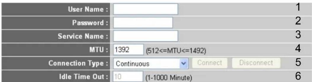
Enter the User Name and Password required by your ISP in the appropriate fields. If your ISP has provided you with a "Service Name" enter it in the Service Name field, otherwise, leave it blank.
text_image
User Name : Password : Service Name : MTU : 1392 (512<=MTU<=1492) Connection Type : Continuous Connect Disconnect 5 Idle Time Out : 10 (1-1000 Minute) 6
7
Here are descriptions of every setup items:
User Name (1): Please input user name assigned by your Internet service provider here.
Password (2): Please input the password assigned by your Internet service provider here.
Service Name (3): Please give a name to this Internet service, this is optional
MTU (4): Please input the MTU value of your network connection here. If you don't know, you can use default value.
Connection Type (5): Please select the connection type of Internet connection you wish to use (detailed explanation listed below).
Idle Time Out (6): Please input idle time out, (detailed explanation listed below).
When you finish with all settings, please click 'OK' (7); if you want to go back to previous menu, click 'Back'.
MTU - Please use default value if you don't know what it is, or ask your service provider for a proper value.
Connection Type - There are 3 options: ‘Continuous’ - keep internet connection alive, do not disconnect, connect on Demand - only connects to Internet when there’s a connect attempt, and ‘Manual’ - only connects to Internet when ‘Connect’ button on this page is pressed, and disconnects when ‘Disconnect button is pressed.
Idle Time Out: Specify the time to shutdown internet connect after no internet activity is detected by minute. This option is only available when connection type is ‘Connect on Demand’.
2.3.4. Setup Procedure for 'PPTP xDSL'
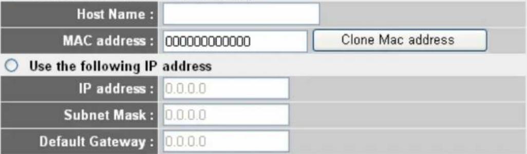
PPTP xDSL requires two kinds of setting: WAN interface setting (setup IP address) and PPTP setting (PPTP user name and password). Here we start from WAN interface setting:
• WAN Interface Settings
Obtain an IP address automatically
text_image
Host Name : MAC address : 000000000000 Clone Mac address Use the following IP address IP address : 0.0.0.0 Subnet Mask : 0.0.0.0 Default Gateway : 0.0.0.0Select the type of how you obtain IP address from your service provider here. You can choose 'Obtain an IP address automatically' (equal to DHCP, please refer to 'Cable Modem' section above), or 'Use the following IP address' (i.e. static IP address).
WAN interface settings must be correctly set, or the Internet connection will fail even those settings of PPTP settings are correct. Please contact your Internet service provider if you don't know what you should fill in these fields.
Now please go to PPTP settings section:
- PPTP Settings
text_image
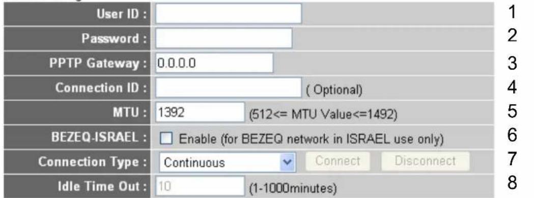
User ID : Password : PPTP Gateway : 0.0.0.0 Connection ID : ( Optional ) MTU : 1392 (512<= MTU Value<=1492) BEZEQ-ISRAEL : Enable (for BEZEQ network in ISRAEL use only) Connection Type : Continuous Connect Disconnect Idle Time Out : 10 (1-1000minutes)
Here are descriptions of every setup items:
User Name (1): Please input user ID (user name) assigned by your Internet service provider here.
Password (2): Please input the password assigned by your Internet service provider here.
PPTP Gateway (3): Please input the IP address of PPTP gateway assigned by your Internet service provider here.
Connection ID (4): Please input the connection ID here, this is optional and you can leave it blank.
MTU (5): Please input the MTU value of your network connection here. If you don't know, you can use default value.
BEZEQ-ISRAEL (6): Setting item ‘BEZEQ-ISRAEL’ is only required to check if you’re using the service provided by BEZEQ network in Israel.
Connection type (7): Please select the connection type of Internet connection you wish to use, please refer to last section for detailed descriptions.
Idle Time Out (8): Please input the idle time out of Internet connection you wish to use, and refer to last section for detailed descriptions.
When you finish with all settings, please click 'OK (9); if you want to go back to previous menu, click 'Back'.
2.3.5. Setup Procedure for 'L2TP xDSL'
L2TP is another popular connection method for xDSL and other Internet connection types, and all required setting items are the same with PPTP connection.
Like PPTP, there are two kinds of required setting, we'll start from 'WAN Interface Settings':
• WAN Interface Settings
Obtain an IP address automatically
text_image
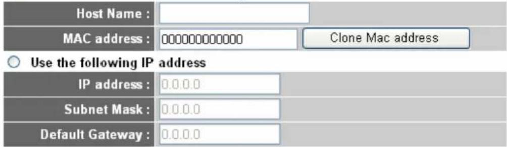
Host Name : MAC address : 0000000000000 Clone Mac address Use the following IP address IP address : 0.0.0.0 Subnet Mask : 0.0.0.0 Default Gateway : 0.0.0.0Please select the type of how you obtain IP address from your service provider here. You can choose 'Obtain an IP address automatically' (equal to DHCP, please refer to 'Cable Modem' section above), or 'Use the following IP address' (equal to static IP address, please refer to 'PPPoE xDSL' section above).
WAN interface settings must be correctly set, or the Internet connection will fail even those settings of PPTP settings are correct. Please contact your Internet service provider if you don't know what you should fill in these fields.
Now please go to L2TP settings section:
- L2TP Settings
text_image
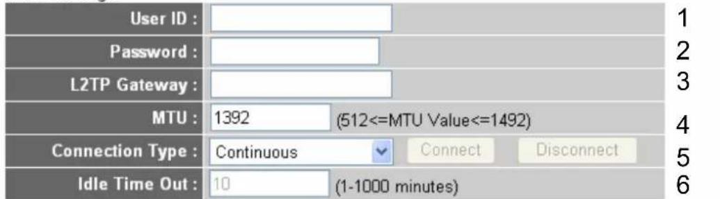
User ID : Password : L2TP Gateway : MTU : 1392 (512<=MTU Value<=1492) Connection Type : Continuous Connect Disconnect Idle Time Out : 10 (1-1000 minutes)
Here are descriptions of every setup items:
User Name (1): Please input user ID (user name) assigned by your Internet service provider here.
Password (2): Please input the password assigned by your Internet service provider here.
L2TP Gateway (3): Please input the IP address of PPTP gateway assigned by your Internet service provider here.
MTU (4): Please input the MTU value of your network connection here. If you don't know, you can use default value.
Connection type (5): Please select the connection type of Internet connection you wish to use, please refer to last section for detailed descriptions.
Idle Time Out (6): Please input the idle time out of Internet connection you wish to use, and refer to last section for detailed descriptions.
When you finish with all settings, please click 'OK (7); if you want to go back to previous menu, click 'Back'.
2.3.6. Setup Procedure for 'Telstra Big Pond'
Telstra Big Pond (Australia Only)
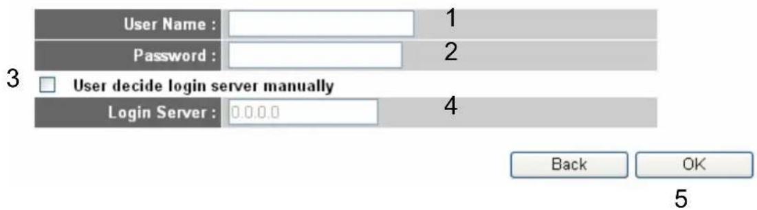
If your Internet service is provided by Telstra Big Pond in Australia, you will need to enter your information below. This information is provided by Teistra BigPond.
text_image
User Name : 1 Password : 2 3 User decide login server manually Login Server : 0.0.0.0 4 Back OK 5This setting only works when you're using Telstra big pond's network service in Australia. You need to input:
User Name (1): Please input the user name assigned by Telstra.
Password (2): Please input the password assigned by Telstra.
User decide login Check this box to choose login server by yourself. server manually (3):
Login Server(4): Please input the IP address of login server here.
When you finish with all settings, click 'OK (5); if you want to go back to previous menu, click 'Back'.
When all settings are finished, you'll see the following message displayed on your web browser:
Save settings successfully!
Please press APPLY button to restart the system to make the changes take effect.
APPLY
Please click 'Apply' button to prepare to restart the router, and you'll see this message:
System Restarting! Please wait for a while!
OK(26)
Please wait for about 30 seconds, then click 'OK!' button. You'll be back to router management interface again, and the router is ready with new settings.
2.4. Basic Setup
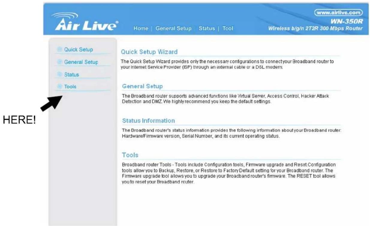
In this chapter, you'll know how to change the time zone, password, and remote management settings. Please start your web browser and log onto router web management interface, then click 'General Setup' button on the left, or click 'General Setup' link at the upper-right corner of web management interface.
text_image
Air Live® Home | General Setup | Status | Tool www.airlive.com WN-350R Wireless b/g/n 2T2R 300 Mbps Router Quick Setup Wizard The Quick Setup Wizard provides only the necessary configurations to connect your Broadband router to your Internet Service Provider (ISP) through an external cable or a DSL modem. General Setup The Broadband router supports advanced functions like Virtual Server, Access Control, Hacker Attack Detection and DMZ. We highly recommend you keep the default settings. Status Information The Broadband router's status information provides the following information about your Broadband router: Hardware/Firmware version, Serial Number, and its current operating status. Tools Broadband router Tools - Tools include Configuration tools, Firmware upgrade and Reset Configuration tools allow you to Backup, Restore, or Restore to Factory Default setting for your Broadband router. The Firmware upgrade tool allows you to upgrade your Broadband router's firmware. The RESET tool allows you to reset your Broadband router. HERE!2.4.1. Time Zone and Time Auto-synchronization
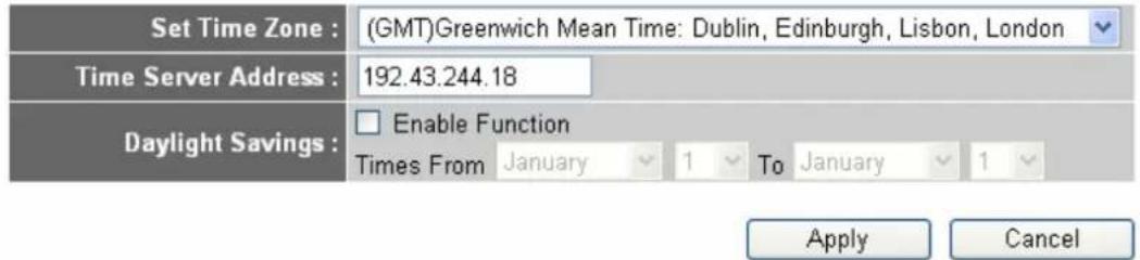
Please follow the following instructions to set time zone and time auto-synchronization parameters:
Time Zone 2
Set the time zone of the Broadband router. This information is used for log entries and firewall settings.
text_image
Set Time Zone : (GMT)Greenwich Mean Time: Dublin, Edinburgh, Lisbon, London Time Server Address : 192.43.244.18 Daylight Savings : Enable Function Times From January 1 To January 1 Apply CancelPlease click 'System' menu on the left of web management interface, then click 'Time Zone', and the following message will be displayed on your web browser: Please select time zone at 'Set time zone' drop-down list, and input the IP address or host name of time server. If you want to enable daylight savings setting, please check 'Enable Function' box, and set the duration of daylight setting. When you finish, click 'Apply'. You'll see the following message displayed on web browser:
Save settings successfully!
You may press CONTINUE button to continue configuring other settings or press APPLY button to restart the system to make the changes take effect.
CONTINUE
APPLY
Press ‘Continue’ to save the settings made and back to web management interface; press ‘Apply’ to save the settings made and restart the router so the settings will take effect after it reboots.
NOTE: You can refer to the instructions given in last chapter: 'Using Quick Setup', for detailed descriptions on time zone settings.
2.4.2. Change Management Password
Default password of this router is airlive, and it's displayed on the login prompt when accessed from web browser. There's a security risk if you don't change the default password, since everyone can see it. This is very important when you have wireless function enabled.
To change password, please follow the following instructions:
Please click 'System' menu on the left of web management interface, then click 'Password Settings', and the following message will be displayed on your web browser:
Password Settings 2
You can change the password required to log into the broadband router's system web-based management. By default, the password is airlive. So please assign a password to the Administrator as soon as possible, and store it in a safe place. Passwords can contain 0 to 30 alphanumeric characters, and are case sensitive.
text_image
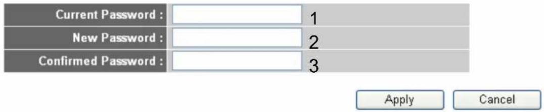
Current Password : New Password : Confirmed Password : Apply CancelHere are descriptions of every setup items:
Current Password (1): Please input current password here.
New Password (2): Please input new password here.
Confirmed Password (3): Please input new password here again.
When you finish, click 'Apply'. If you want to keep original password unchanged, click 'Cancel'.
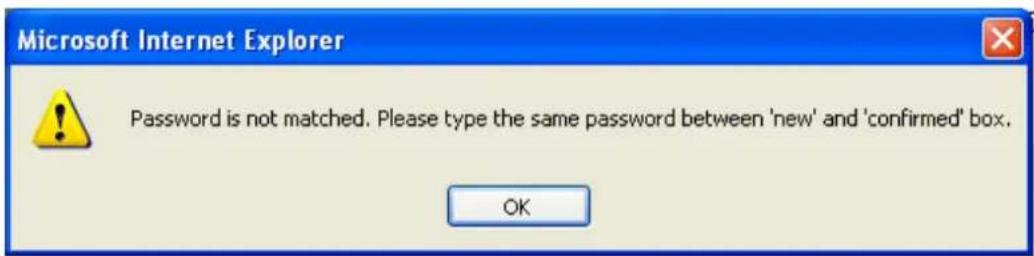
If the password you typed in 'New Password' (2) and 'Confirmed Password' (3) field are not the same, you'll see the following message:
text_image
Microsoft Internet Explorer Password is not matched. Please type the same password between 'new' and 'confirmed' box. OKPlease retype the new password again when you see above message.
If you see the following message:
ERROR: Password is not matched!

It means the content in 'Current Password' field is wrong, please click 'OK' to go back to previous menu, and try to input current password again.
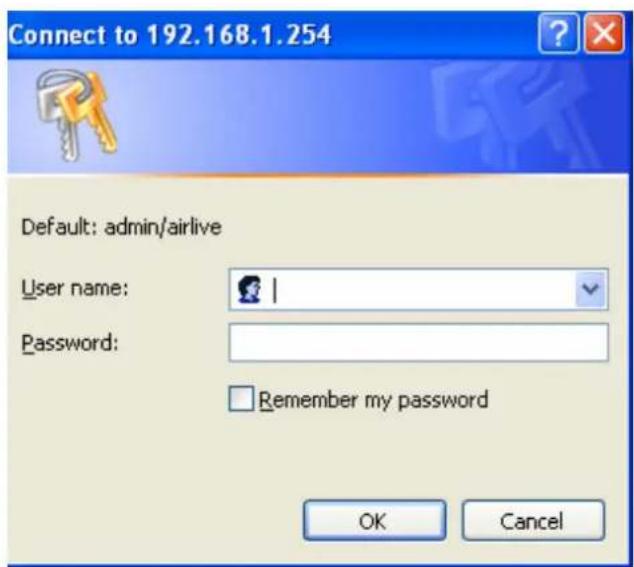
If the current and new passwords are correctly entered, after you click 'Apply', you'll be prompted to input your new password:
text_image
Connect to 192.168.1.254 Default: admin/airlive User name: Password: Remember my password OK CancelPlease use new password to enter web management interface again, and you should be able to login with new password.
2.4.3. Remote Management
This router does not allow management access from Internet, to prevent possible security risks (especially when you defined a weak password, or didn't change default password). However, you can still management this router from a specific IP address by enabling the 'Remote Management' Function.
To do so, please follow the following instructions:
Please click 'System' menu on the left of web management interface, then click 'Remote Management', and the following message will be displayed on your web browser:
Remote Management?
The remote management function allows you to designate a host in the Internet to have management/configuration access to the Broadband router from a remote site. Enter the designated host IP Address in the Host IP Address field.

text_image
Host address 0.0.0.0 1 Port 8080 2 Enabled Apply Cancel4
Here are descriptions of every setup items:
Host Address (1): Input the IP address of the remote host you wish to initiate a management access.
Port (2): You can define the port number this router should expect an incoming request. If you're providing a web service (default port number is 80), you should try to use other port number. You can use the default port setting '8080', or something like '32245' or '1429'. (Any integer between 1 and 65534)
Enabled (3): Select the field to start the configuration.
When you finish with all settings, click 'Apply', and you'll see the following message displayed on web browser:
Save settings successfully!
You may press CONTINUE button to continue configuring other settings or press APPLY button to restart the system to make the changes take effect.
CONTINUE
APPLY
Press ‘Continue’ to save the settings made and back to web management interface; press ‘Apply’ to save the settings made and restart the router so the settings will take effect after it reboots.
NOTE: When you want to manage this router from another computer on internet, you have to input the IP address and port number of this router. If your Internet service provider assigns you with a static IP address, it will not be a problem; but if the IP address your service provider assigns to you will vary every time you establish an internet connection, this will be a problem.
Please either asks your service provider to give you a static IP address, or use dynamic IP to host name mapping services like DDNS. Please refer to chapter 2-5-8 'DDNS client' for details.
NOTE: Default port number the web browser will use is '80'. If the 'Port' setting in this page is not '80', you have to assign the port number in the address bar of web browser manually. For example, if the IP address of this router is 1.2.3.4, and the port number you set is 8888, you have to input following address in the address bar of web browser:
http://1.2.3.4:8888
2.5. Setup Internet Connection (WAN Setup)
Internet connections setup can be done by using 'Quick Setup' menu described in chapter 2-3. However, you can setup WAN connections up by using WAN configuration menu. You can also set advanced functions like DDNS (Dynamic DNS) here.
To start configuration, please follow the following instructions:
Please click 'WAN' menu on the left of web management interface, and the following message will be displayed on your web browser:
Please select an Internet connection method depend on the type of connection you're using. You can either click the connection method on the left (1) or right (2). If you select the connection method on the right, please click 'More Configuration' button after a method is selected.
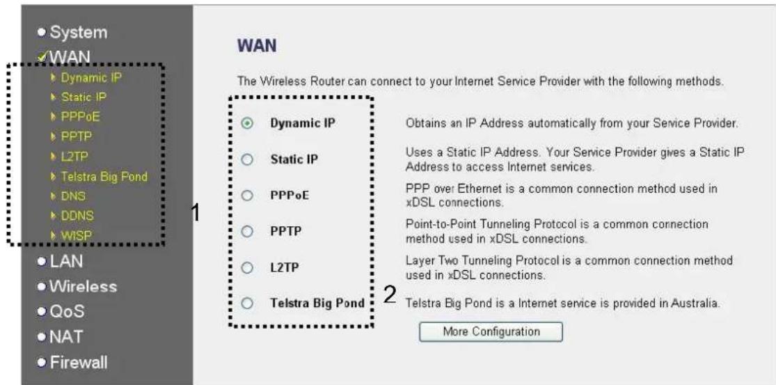
text_image
System WAN Dynamic IP Static IP PPPoE PPTP L2TP Telstra Big Pond DNS DDNS WISP LAN Wireless QoS NAT Firewall 1 WAN The Wireless Router can connect to your Internet Service Provider with the following methods. Dynamic IP Static IP PPPoE PPTP L2TP Telstra Big Pond 2 Obtains an IP Address automatically from your Service Provider. Uses a Static IP Address. Your Service Provider gives a Static IP Address to access Internet services. PPP over Ethernet is a common connection method used in xDSL connections. Point-to-Point Tunneling Protocol is a common connection method used in xDSL connections. Layer Two Tunneling Protocol is a common connection method used in xDSL connections. Telstra Big Pond is a Internet service is provided in Australia. More ConfigurationDynamic IP - Please go to section 2.5.1.
Static IP - Please go to section 2.5.2.
PPPoE - Please go to section 2.5.3.
PPTP - Please go to section 2.5.4.
L2TP - Please go to section 2.5.5.
Telstra Big Pond - Please go to section 2.5.6.
DNS - Please go to section 2.5.7.
DDNS - Please go to section 2.5.8.
WISP - Please go to section 2.5.9.
2.5.1. Setup Procedure for 'Dynamic IP'
Dynamic IP 2
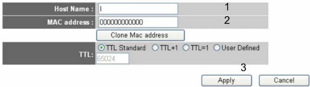
The Host Name is optional, but may be required by some Service Providers. The default MAC Address is set to the WAN physical interface on the Broadband router. If required by your Service Provider, you can use the 'Clone MAC Address' button to copy the MAC Address of the Network Interface Card installed in your PC and replace the WAN MAC Address with this MAC Address.
text_image
Host Name : 1 MAC address : 000000000000 Clone Mac address TTL: TTL Standard ○ TTL+1 ○ TTL=1 ○ User Defined 65024 Apply CancelHere are descriptions of every setup items:
Host Name (1): Please input host name of your computer, this is optional, and only required if your service provider asks you to do so.
MAC Address (2): Please input MAC address of your computer, if your service provider only permits computer with certain MAC address to access internet. If you're using the computer which used to connect to Internet via cable modem, you can simply press 'Clone Mac address' button to fill the MAC address field with the MAC address of your computer,
After you finish with all settings, please click 'Apply' (3); if you want to remove and value you entered, please click 'Cancel'.
After you click 'Apply', the following message will be displayed on your web browser:
Save settings successfully!
You may press CONTINUE button to continue configuring other settings or press APPLY button to restart the system to make the changes take effect.
CONTINUE
APPLY
Please click 'Continue' (1) to back to previous setup menu; to continue on router setup, or click 'Apply' to reboot the router so the settings will take effect (Please wait for about 30 seconds while router is rebooting).
2.5.2. Setup Procedure for 'Static IP'
Static IP 2
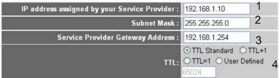
If your Service Provider has assigned a Fixed IP address; enter the assigned IP Address, Subnet Mask and the Gateway IP Address provided.
text_image
IP address assigned by your Service Provider : 192.168.1.10 Subnet Mask : 255.255.255.0 Service Provider Gateway Address : 192.168.1.254 TTL: ○ TTL Standard ○ TTL+1 ○ TTL=1 ○ User Defined 65024
Here are descriptions of every setup items:
IP address assigned Please input IP address assigned by your service by your Service provider.
Provider (1):
Subnet Mask (2): Please input subnet mask assigned by your service provider
Service Provider Please input the IP address of DNS server
Gateway Address (3): provided by your service provider.
After you finish with all settings, please click 'Apply' (4) button and the following message will be displayed on your web browser:
Save settings successfully!
You may press CONTINUE button to continue configuring other settings or press APPLY button to restart the system to make the changes take effect.
CONTINUE
APPLY
Please click 'Continue' to back to previous setup menu; to continue on other setup procedures, or click 'Apply' to reboot the router so the settings will take effect (Please wait for about 30 seconds while router is rebooting).
If you want to reset all settings in this page back to previously-saved value, please click 'Cancel' button.
2.5.3. Setup Procedure for 'PPPoE'
PPPoE 2
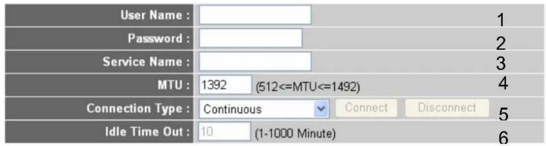
Enter the PPPoE User Name and Password assigned by your Service Provider. The Service Name is normally optional, but may be required by some Service Providers. Enter a Idle Time (in minutes) to define a maximum period of time for which the Internet connection is maintained during inactivity. If the connection is inactive for longer than the Maximum Idle Time, then the connection will be dropped. You can enable the Connect on Demand option to automatically re-establish the connection as soon as you attempt to access the Internet again. If your Internet Service Provider requires the use of PPPoE, enter the information below.
text_image
User Name : Password : Service Name : MTU : 1392 (512<=MTU<=1492) Connection Type : Continuous Connect Disconnect Idle Time Out : 10 (1-1000 Minute)
Here are descriptions of every setup items:
User Name (1): Please input user name assigned by your Internet service provider here.
Password (2): Please input the password assigned by your Internet service provider here.
Service Name (3): Please give a name to this Internet service, this is optional
MTU (4): Please input the MTU value of your network connection here. If you don't know, you can use default value.
Connection Type (5): Please select the connection type of Internet connection you wish to use.
Continuous – The connection will be kept always on. If the connection is interrupted, the router will re-connect automatically.
Connect On-Demand – Only connect when you want to surf the Internet. “Idle Time Out” is set to stop the connection when the network traffic is not sending or receiving after an idle time.
Manual – After you have selected this option, you will see the "Connect" button and "Disconnect" button, click "Connect" and the router will connect to the ISP. If you want to stop the connection, please click "Disconnect" button.
Idle Time Out (6): If you have selected the connection type to "Connect-On-Demand", please input the idle time out.
After you finish with all settings, please click 'Apply' (7) button and the following message will be displayed on your web browser:
Save settings successfully!
You may press CONTINUE button to continue configuring other settings or press APPLY button to restart the system to make the changes take effect.
CONTINUE
APPLY
Please click 'Continue' to back to previous setup menu; to continue on other setup procedures, or click 'Apply' to reboot the router so the settings will take effect (Please wait for about 30 seconds while router is rebooting).
If you want to reset all settings in this page back to previously-saved value, please click 'Cancel' button.
2.5.4. Setup Procedure for 'PPTP'
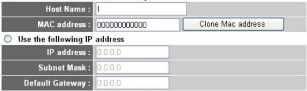
PPTP requires two kinds of setting: WAN interface setting (setup IP address) and PPTP setting (PPTP user name and password). Here we start from WAN interface setting:
• WAN Interface Settings
Obtain an IP address automatically
text_image
Host Name : 1 MAC address : 0000000000000 Clone Mac address Use the following IP address IP address : 0.0.0.0 Subnet Mask : 0.0.0.0 Default Gateway : 0.0.0.0Select the type of how you obtain IP address from your service provider here. You can choose 'Obtain an IP address automatically' (equal to DHCP, please refer to 'Cable Modem' section above), or 'Use the following IP address' (i.e. static IP address)
WAN interface settings must be correctly set, or the Internet connection will fail even those settings of PPTP settings are correct. Please contact your Internet service provider if you don't know what you should fill in these fields.
Now please go to PPTP settings section:
- PPTP Settings
text_image
User ID : Password : PPTP Gateway : 0.0.0.0 Connection ID : ( Optional ) MTU : 1392 (512<= MTU Value<=1492) BEZEQ-ISRAEL : Enable (for BEZEQ network in ISRAEL use only) Connection Type : Continuous Connect Disconnect Idle Time Out : 10 (1-1000minutes)Apply 9
Cancel
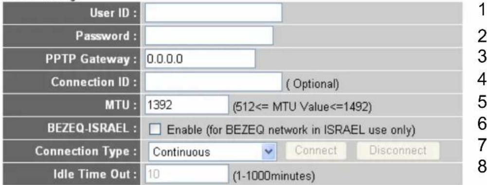
Here are descriptions of every setup items:
User Name (1): Please input user ID (user name) assigned by your Internet service provider here.
Password (2): Please input the password assigned by your Internet service provider here.
PPTP Gateway (3): Please input the IP address of PPTP gateway assigned by your Internet service provider here.
Connection ID (4): Please input the connection ID here, this is optional and you can leave it blank.
MTU (5): Please input the MTU value of your network connection here. If you don't know, you can use default value.
BEZEQ-ISRAEL (6): If you are connecting to the BEZEQ network in Israel. Please enable this function.
Connection type (7): Please select the connection type of Internetconnection you wish to use, please refer to section 2-5-3 for detailed descriptions.
Idle Time Out (8): Please input the idle time out of Internet connection you wish to use, and refer to section 2-5-3 for detailed descriptions.
When you finish with all settings, please click 'Apply' (9) button and the following message will be displayed on your web browser:
Save settings successfully!
You may press CONTINUE button to continue configuring other settings or press APPLY button to restart the system to make the changes take effect.
CONTINUE
APPLY
Please click 'Continue' to back to previous setup menu; to continue on other setup procedures, or click 'Apply' to reboot the router so the settings will take effect (Please wait for about 30 seconds while router is rebooting).
If you want to reset all settings in this page back to previously-saved value, please click 'Cancel' button.
2.5.5. Setup Procedure for 'L2TP'
• L2TP Settings
text_image
User ID : Password : L2TP Gateway : MTU : 1392 (512<=MTU Value<=1492) Connection Type : Continuous Connect Disconnect Idle Time Out : 10 (1-1000 minutes)Apply 7
Cancel
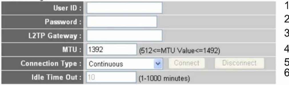
Here are descriptions of every setup items:
User ID (1): Please input user ID (user name) assigned by your Internet service provider here.
Password (2): Please input the password assigned by your Internet service provider here.
L2TP Gateway (3): Please input the IP address of PPTP gateway assigned by your Internet service provider here.
MTU (4): Please input the MTU value of your network connection here. If you don't know, you can use default value.
Connection type (5): Please select the connection type of Internet connection you wish to use, please refer to section 2-5-3 for detailed descriptions.
Idle Time Out (6): Please input the idle time out of Internet connection you wish to use, and refer to section 2-5-3 for detailed descriptions.
When you finish with all settings, please click 'Apply' (7) button and the following message will be displayed on your web browser:
Save settings successfully!
You may press CONTINUE button to continue configuring other settings or press APPLY button to restart the system to make the changes take effect.
CONTINUE
APPLY
Please click 'Continue' to back to previous setup menu; to continue on other setup procedures, or click 'Apply' to reboot the router so the settings will take effect (Please wait for about 30 seconds while router is rebooting).
If you want to reset all settings in this page back to previously-saved value, please click 'Cancel' button.
2.5.6. Setup Procedure for 'Telstra Big Pond'
Telstra Big Pond
If your Internet service is provided by Telstra Big Pond in Australia, you will need to enter your information below. This information is provided by Teistra BigPond.
3
text_image
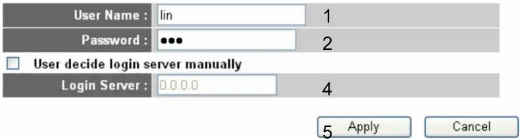
User Name : lin 1 Password : ••• 2 □ User decide login server manually Login Server : 0.0.0.0 4 5 Apply CancelThis setting only works when you're using Telstra big pond's network service in Australia. You need to input:
User Name (1): Please input the user name assigned by Telstra.
Password (2): Please input the password assigned by Telstra.
Assign login Check this box to choose login server by yourself. server manually (3):
Server IP Address (4): Please input the IP address of login server here.
When you finish with all settings, click 'Apply' (5) button and the following message will be displayed on your web browser:
Save settings successfully!
You may press CONTINUE button to continue configuring other settings or press APPLY button to restart the system to make the changes take effect.
CONTINUE
APPLY
Please click 'Continue' to back to previous setup menu; to continue on other setup procedures, or click 'Apply' to reboot the router so the settings will take effect (Please wait for about 30 seconds while router is rebooting).
If you want to reset all settings in this page back to previously-saved value, please click 'Cancel' button.
2.5.7. Setup Procedure for 'DNS'
If you select 'Dynamic IP' or 'PPPoE' as Internet connection method, at least one DNS server's IP address should be assigned automatically. However, if you have preferred DNS server, or your service provider didn't assign the IP address of DNS server because of any reason, you can input the IP address of DNS server here.
DNS
A Domain Name System (DNS) server is like an index of IP Addresses and Web Addresses. If you type a Web address into your browser, such as www.broadbandrouter.com, a DNS server will find that name in its index and find the matching IP address. Most ISPs provide a DNS server for speed and convenience. Since your Service Provider may connect you to the Internet through dynamic IP settings, it is likely that the DNS server IP Address is also provided dynamically. However, if there is a DNS server that you would rather use, you need to specify the IP Address of that DNS server. The primary DNS will be used for domain name access first, in case the primary DNS access failures, the secondary DNS will be used.
Has your Internet service provider given you a DNS address?

flowchart
graph TD
    A["DNS address :"] --> B["1"]
    C["Secondary DNS Address (optional) :"] --> D["2"]
    E["Apply"] --> F["Cancel"]
Here are descriptions of every setup items:
DNS Address (1): Please input the IP address of DNS server provided by your service provider.
Secondary Please input the IP address of another DNS
DNS Address (2): server provided by your service provider, this is optional.
NOTE: Only IP address can be entered here; DO NOT use the hostname of DNS server! (i.e. only numeric characters and dots are accepted)
10.20.30.40...... Correct dns.serviceprovider.com...... Incorrect
After you finish with all settings, please click 'Apply' (3) button and the following message will be displayed on your web browser:
Save settings successfully!
You may press CONTINUE button to continue configuring other settings or press APPLY button to restart the system to make the changes take effect.
CONTINUE
APPLY
Please click 'Continue' to back to previous setup menu; to continue on other setup procedures, or click 'Apply' to reboot the router so the settings will take effect (Please wait for about 30 seconds while router is rebooting).
If you want to reset all settings in this page back to previously-saved value, please click 'Cancel' button.
2.5.8. Setup Procedure for 'DDNS'
DDNS (Dynamic DNS) is an IP-to-Hostname mapping service for those Internet users who don't have a static (fixed) IP address. It will be a problem when such user wants to provide services to other users on Internet, because their IP address will vary every time when connected to Internet, and other user will not be able to know the IP address they're using at a certain time.
This router supports DDNS service of several service providers, for example:
DynDNS (http://www.dyndns.org)
TZO (http://www.tzo.com)
Please go to one of DDNS service provider's webpage listed above, and get a free DDNS account by the instructions given on their webpage.
DDNS 2
DDNS allows users to map the static domain name to a dynamic IP address. You must get a account, password and your static domain name from the DDNS service providers. Our products have DDNS support for www.dyndns.org and www.tzo.com now.
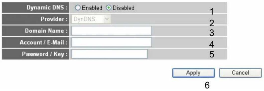
text_image
Dynamic DNS : Enabled Disabled 1 Provider : DynDNS 2 Domain Name : Account / E-Mail : Password / Key : Apply Cancel 6Here are descriptions of every setup items:
Dynamic DNS (1): If you want to enable DDNS function, please select 'Enabled'; otherwise please select 'Disabled'.
Provider (2): Select your DDNS service provider here.
Domain Name (3): Input the domain name you've obtained from DDNS service provider.
Account / E-Mail (4): Input account or email of DDNS registration.
Password / Key (5): Input DDNS service password or key.
After you finish with all settings, please click 'Apply' (6) button and the following message will be displayed on your web browser:
Save settings successfully!
You may press CONTINUE button to continue configuring other settings or press APPLY button to restart the system to make the changes take effect.
CONTINUE
APPLY
Please click 'Continue' to back to previous setup menu; to continue on other setup procedures, or click 'Apply' to reboot the router so the settings will take effect (Please wait for about 30 seconds while router is rebooting).
If you want to reset all settings in this page back to previously-saved value, please click 'Cancel' button.
2.5.9. Setup Procedure for 'WISP'
If your network service provided by your service provider is through wireless network, please select this mode. After you have connected the router to the access point of service provider wirelessly, please setup the WAN connection type in WAN page.
WISP
In this mode, all ethernet ports are bridged together and the wireless client will connect to ISP access point. The NAT is enabled and PCs in ethernet ports share the same IP to ISP through wireless LAN. You must set the wireless to client mode first and connect to the ISP AP in Site-Survey page. The connection type can be setup in WAN page by using PPPOE, DHCP client, PPTP client or static IP.
Disable Enable staEnable 1
APPLY CANCEL
Here are descriptions of every setup items:
Disable/Enable/ There are three selections for disable or disable staEnable (1): wireless ISP functions.
Disable: disable this function.
Enable: enable this function and the router can connect to the access points installed by your wireless service provider. Any clients associated to the router can access the Internet service through the wireless network.
Note: In this mode, if you are informed by your wireless ISP that the wireless settings of the access point is changed, please configure the router in this page for match the settings.
staEnable: enable this function and the router can only allow to be connected through wired Ethernet cable for WAN access service.
SSID (2): This is the name of wireless network. Input the SSID name that your wireless ISP provide to you.
Channel Number (3): This is the radio frequency used to transmit and receive the wireless signal. The wireless devices in the same network should follow the same setting. Select the channel designated by your wireless ISP.
Site Survey (4): Click 'Select Site Survey' button, then a "Wireless Site Survey Table" will pop up. It will list all available access points nearby. Select the access point designated by your wireless ISP in the table and the router will join wireless network through this access point.
Security Settings (5): If the access point enables wireless security, you have to follow the same settings in order to access the access point. Click to set security settings for this connection (Please go to section '2-7-3 Wireless Security' for detailed instructions).
After you finish with all settings, please click 'Apply' (6) button and the following message will be displayed on your web browser:
Save settings successfully!
You may press CONTINUE button to continue configuring other settings or press APPLY button to restart the system to make the changes take effect.
CONTINUE
APPLY
Please click 'Continue' to back to previous setup menu; to continue on other setup procedures, or click 'Apply' to reboot the router so the settings will take effect (Please wait for about 30 seconds while router is rebooting).
If you want to reset all settings in this page back to previously-saved value, please click 'Cancel' button.
2.6. Wired LAN Configurations
Before all computers using wired Ethernet connection (i.e. those computers connect to this router's LAN port 1 to 4 by Ethernet cable) can communicate with each other and access internet, they must have a valid IP address.
There are two ways to assign IP addresses to computers: static IP address (set the IP address for every computer manually), and dynamic IP address (IP address of computers will be assigned by router automatically. It's recommended for most of computers to use dynamic IP address, it will save a lot of time on setting IP addresses for every computer, especially when there are a lot of computers in your network; for servers and network devices which will provide services to other computer and users that come from Internet, static IP address should be used, so other computes can locate the server.
Suggestions on IP address numbering plan:
If you have no idea on how to define an IP address plan for your network, here are some suggestions.
- A valid IP address has 4 fields: a.b.c.d, for most of home and company users, it's suggested to use 192.168.c.d, where c is an integer between 0 and 254, and d is an integer between 1 and 254. This router is capable to work with up to 253 clients, so you can set 'd' field of IP address of router as 1 or 254 (or any number between 1 and 254), and pick a number between 0 and 254 for field 'c'.
- In most cases, you should use '255.255.255.0' as subnet mask, which allows up to 253 clients (this also meets router's capability of working with up to 253 clients).
- For all servers and network devices which will provide services to other people (like Internet service, print service, and file service), they should use static IP address. Give each of them a unique number between 1 and 253, and maintain a list, so everyone can locate those servers easily.
- For computers which are not dedicated to provide specific service to others, they should use dynamic IP address.
If you don't really understand the descriptions listed above, don't worry! We will provide recommended setup values below.
Please follow the following instructions to set wired LAN parameters.
Please click 'LAN' menu on the left of web management interface, there are three setup groups here: 'LAN IP', 'DHCP Server', and 'Static DHCP Leases Table'. Here are setup instructions for each of them.
2.6.1. LANIP Section
• LAN IP
| IP address | 192.168.1.254 | 1 |
| Subnet Mask | 255.255.255.0 | 2 |
| 802.1d Spanning Tree | Disabled | 3 |
| DHCP Server | Enabled | 4 |
Here are descriptions of every setup items:
IP address (1): Please input the IP address of this router.
Subnet Mask (2): Please input subnet mask for this network.
802.1d If you wish to activate 802.1d spanning tree
Spanning Tree (3): function, select 'Enabled' for setup item '802.1d Spanning Tree', or set it to 'Disabled'
DHCP Server (4): If you want to activate DHCP server function of this router, select 'Enabled', or set it to 'Disabled'.
Recommended Value if you don't know what to fill:
IP Address: 192.168.1.254
Subnet Mask: 255.255.255.0
802.1d Spanning Tree: Disabled
DHCP Server: Enabled
2.6.2.DHCPServer
- DHCP Server
| Lease Time | Half hour | 1 |
| Start IP | 192.168.1.100 | 2 |
| End IP | 192.168.1.200 | 3 |
| Domain Name | Airlive | 4 |
These settings are only available when 'DHCP Server' in 'LAN IP' section is 'Enabled', and here are descriptions of every setup items:
Lease Time (1): Please choose a lease time (the duration that every computer can keep a specific IP address) of every IP address assigned by this router from dropdown menu.
Start IP (2): Please input the start IP address of the IP range.
End IP (3): Please input the end IP address of the IP range.
Domain Name (4): If you wish, you can also optionally input the domain name for your network. This is optional.
Recommended Value if you don't know what to fill:
Lease Time: Two Weeks (or 'Forever', if you have less than 20 computers)
Start IP: 192.168.1.25400
End IP: 192.168.2.200
Domain Name: (leave it blank)
NOTE:
- The number of the last field (mentioned 'd' field) of 'End IP' must be greater than 'Start IP', and can not the same with router's IP address.
- The former three fields of IP address of 'Start IP', 'End IP', and 'IP Address of 'LAN IP' section (mentioned 'a', 'b', and 'c' field) should be the same.
- These settings will affect wireless clients too.
2.6.3. Static DHCP Leases Table
This function allows you to assign a static IP address to a specific computer forever, so you don't have to set the IP address for a computer, and still enjoy the benefit of using DHCP server. Maximum 16 static IP addresses can be assigned here.
(If you set 'Lease Time' to 'forever' in 'DHCP Server' section, you can also assign an IP address to a specific computer permanently, however, you will not be able to assign a certain IP address to a specific computer, since IP addresses will be assigned in random order by this way).
1
√ Enable Static DHCP Leases

text_image
New MAC address : 001122334455 IP address : 192.168.1.100 Add Clear 2 34
Here are descriptions of every setup items:
Enable Static Check this box to enable this function, otherwise
DHCP Leases (1): uncheck it to disable this function.
MAC Address (2): Input the MAC address of the computer or network device (total 12 characters, with character from 0 to 9, and from a to f, like '001122aabbcc')
IP address (3): Input the IP address you want to assign to this computer or network device
'Add' (4): After you inputted MAC address and IP address pair, click this button to add the pair to static DHCP leases table.
If you want to remove all characters you just entered, click 'Clear'.
After you clicked 'Add', the MAC address and IP address mapping will be added to 'Static DHCP Leases Table' section.
• Static DHCP Leases Table
It allows to entry 16 sets address only.
| NO. | MAC address | IP address | Select |
| 1 | 00:11:22:33:44:55 | 192.168.1.100 |
If you want to delete a specific item, please check the 'Select' box of a MAC address and IP address mapping (1), then click 'Delete Selected' button (2); if you want to delete all mappings, click 'Delete All' (3). If you want to deselect all mappings, click 'Reset (4).
After you finish all LAN settings, please click 'Apply' button on the bottom of this page. After you click 'Apply', the following message will be displayed on your web browser:
Save settings successfully!
You may press CONTINUE button to continue configuring other settings or press APPLY button to restart the system to make the changes take effect.
CONTINUE
APPLY
Please click 'Continue' to back to previous setup menu; to continue on router setup, or click 'Apply' to reboot the router so the settings will take effect (Please wait for about 30 seconds while router is rebooting).
2.7. Wireless LAN Configurations
If your computer, PDA, game console, or other network devices which is equipped with wireless network interface, you can use the wireless function of this router to let them connect to Internet and share resources with other computers with wired-LAN connection. You can also use the built-in security functions to protect your network from being intruded by malicious intruders.
Please follow the following instructions to set wireless parameters:
Please click 'Wireless' menu on the left of web management interface, and the following message will be displayed on your web browser. You must enable wireless function of this router, or the wireless interface of this router will not function. Please select 'Enable' (1), then click 'Apply' (2) button.
If you're coming here because you want to disable wireless function, please select 'Disable' (3), then click 'Apply' (2) button.
Wireless Settings
The gateway can be quickly configured as a wireless access point for roaming clients by setting the access identifier and channel number. It also supports data encryption and client filtering.
1 3
Enable or disable Wireless module function : ☑ Enable ○ Disable
2
Apply
After you click 'Apply'(2), the following message will be displayed on your web browser:
Save settings successfully!
You may press CONTINUE button to continue configuring other settings or press APPLY button to restart the system to make the changes take effect.
CONTINUE
APPLY
Please click 'Continue' to back to previous setup menu; to continue on other setup procedures, or click 'Apply' to reboot the router so the settings will take effect (Please wait for about 30 seconds while router is rebooting).
2.7.1. Basic Wireless Settings
Please click 'Wireless' menu on the left of web management interface, then click 'Basic Settings', and the following message will be displayed on your web browser:
Basic Settings 2
This page allows you to define ESSID, and Channel for the wireless connection. These parameters are used for the wireless stations to connect to the Access Point.
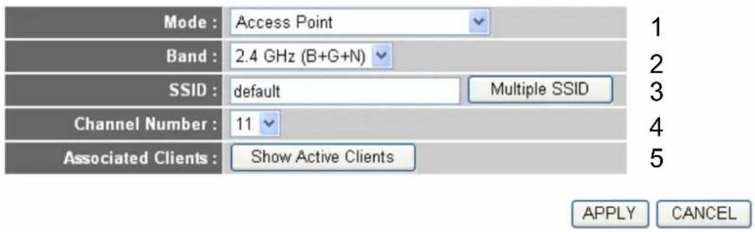
text_image
Mode : Access Point Band : 2.4 GHz (B+G+N) SSID : default Multiple SSID Channel Number : 11 Associated Clients : Show Active Clients 1 2 3 4 5 APPLY CANCELThis wireless router can be work in 6 modes:
- Access Point: Standard wireless AP.
- Station-Infrastructure: Configure the router to Ethernet device such as TV, Game player, HDD&DVD to enable the Ethernet device be a wireless station.
- AP Bridge-Point to Point: Connect this router with another wireless router, to expand the scope of network.
-
AP Bridge-Point to Multi-Point: Connect this router with up to four other wireless routers, to expand the scope of network.
-
AP Bridge-WDS: Connect this router with up to four WDS-capable wireless routers, to expand the scope of network.
- Universal Repeater: The router can act as Station and AP at the same time. It can use Station function to connect to a Root AP and use AP function to service all wireless stations within its coverage.
NOTE: For ‘AP Bridge-Point to Point’ and ‘AP Bridge-Point to Multi-Point’ mode, wireless router is operated in wireless bridge dedicated mode – wireless router is only used to expand the scope of network, and no wireless clients will be accepted. If you want to use your wireless router to expand the scope of network, and also accept wireless clients, please select ‘AP Bridge-WDS’ or ‘Universal Repeater’ mode.
Please select a proper operation mode you want to use from 'Mode' dropdown menu (1), and continue on other operation mode specific settings:
AP
- Please go to section 2.7.1.1.
Station-Infrastructure
- Please go to section 2.7.1.2.
AP Bridge-Point to Point
- Please go to section 2.7.1.3.
AP Bridge-Point to Multi-Point - Please go to section 2.7.1.4.
AP Bridge-WDS
- Please go to section 2.7.1.5.
Universal Repeater
- Please go to section 2.7.1.6.
2.7.1.1. Setup Procedure for 'Access Point'
Please select the radio band you want to use from 'Band' dropdown menu (2), and the following message will be displayed:
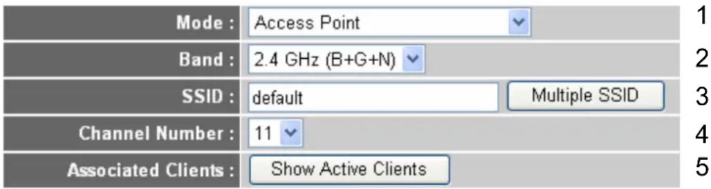
text_image
Mode : Access Point Band : 2.4 GHz (B+G+N) SSID : default Multiple SSID Channel Number : 11 Associated Clients : Show Active ClientsHere are descriptions of every setup items:
Band (2): Please select the radio band from one of following options:
2.4 GHz (B) 2.4GHz band, only allows 802.11b wireless network client to connect this router (maximum transfer rate 11Mbps).
2.4 GHz (N) 2.4GHz band, only allows 802.11n wireless network client to connect this router (maximum transfer rate 300Mbps).
2.4 GHz (B+G) 2.4GHz band, only allows 802.11b and 802.11g wireless network client to connect this router (maximum transfer rate 11Mbps for 802.11b clients, and maximum 54Mbps for 802.11g clients).
2.4 GHz (G) 2.4GHz band, only allows 802.11g wireless network client to connect this router (maximum transfer rate 54Mbps).
2.4 GHz (B+G+N) 2.4GHz band, allows 802.11b, 802.11g, and 802.11n wireless network client to connect this router (maximum transfer rate 11Mbps for 802.11b clients, maximum 54Mbps for 802.11g clients, and maximum 300Mbps for 802.11n clients).
NOTE: For 802.11b and 802.11g mode, the signals can be transmitted only by antenna 1 (The antenna in the right side of the rear panel).
For 802.11n mode: The router is operating in a 1T2R Spatial Multiplexing MIMO configuration. 1 antenna is for signal transmitting and 2 antennas are for signal receiving.
SSID (3): This is the name of wireless router. You can type any alphanumeric characters here, maximum 32 characters. SSID is used to identify your own wireless router from others when there are other wireless routers in the same area. Default SSID is 'default', it's recommended to change default SSID value to the one which is meaningful to you, like myhome, office_room1, etc.
Channel Number (4): Please select a channel from the dropdown list of 'Channel Number', available channel numbers are 1 to 13 for European countries, 1 to 11 for USA. You can choose any channel number you want to use, and almost all wireless clients can locate the channel you're using automatically without any problem. However, it's still useful to remember the channel number you use, some wireless client supports manual channel number select, and this would help in certain scenario when there is some radio communication problem.
Associated Clients (5): Click ‘Show Active Clients’ button, then an “Active Wireless Client Table” will pop up. You can see the status of all active wireless stations that are connecting to the access point.
NOTE: If you don't have special reason to limit the type of allowed wireless client, it's recommended to choose '2.4 GHz (B+G+N) to maximize wireless client compatibility.
TIPS: You can try to change channel number to another one if you think the data transfer rate is too slow. There could be some other wireless routers using the same channel, which will disturb the radio communication between wireless client and the wireless router.
2.7.1.2. Setup Procedure for 'Station-Infrastructure'
In this mode, you can connect the router to Ethernet device such us TV, Game player, HDD&DVD to enable the Ethernet device be a wireless station and join to a wireless network through an access point or AP router.
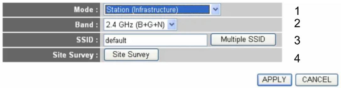
text_image
Mode : Station (Infrastructure) Band : 2.4 GHz (B+G+N) SSID : default Multiple SSID Site Survey : Site Survey 1 2 3 4 APPLY CANCELHere are descriptions of every setup items:
Band (2): Select the band you want to use.
SSID (3): This is the name of wireless network. You can type the SSID of the network you would like to connect here.
Site Survey (4): When you use this wireless router as a wireless station for Ethernet network device to have wireless capability, you have to associate it with a working access point. Click 'Select Site Survey' button, then a "Wireless Site Survey Table" will pop up. It will list all available access points near by. You can select one access point in the table and it will join wireless LAN through this access point.
2.7.1.3. Setup Procedure for 'AP Bridge-Point to Point'
In this mode, you can connect your wireless router with another, to combine two access points and expand the scope of wireless network, and all clients (wired only – AP will not accept wireless clients in this mode) of two wireless routers will think they're on the same physical network. This function is very convenient when you need to connect two networks between two buildings. Here are instructions about how to connect two wireless routers together:
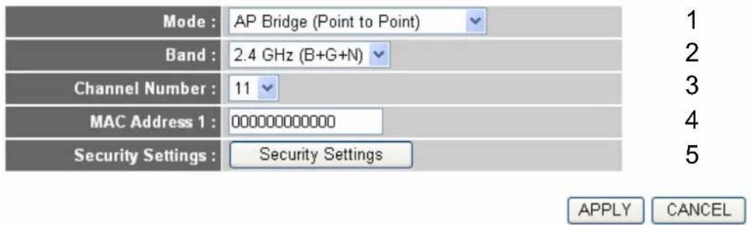
text_image
Mode : AP Bridge (Point to Point) Band : 2.4 GHz (B+G+N) Channel Number : 11 MAC Address 1 : 000000000000 Security Settings : Security Settings 1 2 3 4 5 APPLY CANCELNOTE: Two wireless routers must use the same mode, band, channel number, and security setting!
Here are descriptions of every setup items:
Band (2): Select the band you want to use, two wireless routers must use the same setting.
Channel Number (3): Select the channel you want to use, two wireless routers must use the same setting.
MAC address 1(4): Input the MAC address of another wireless router.
Security Settings (5) Click to setting security for this connection (Please go to section '2.7.3. Wireless Security' for detailed instructions).
2.7.1.4. Setup Procedure for 'AP Bridge-Point to Multi-Point'
In this mode, you can connect your wireless router with at least four wireless routers to expand the scope of wireless network, and all clients (wired only – AP will not accept wireless clients in this mode) of the wireless routers will think they're on the same physical network.
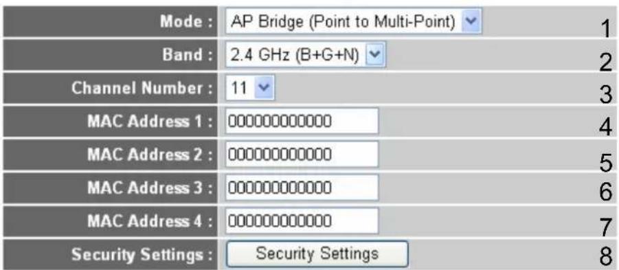
text_image
Mode : AP Bridge (Point to Multi-Point) Band : 2.4 GHz (B+G+N) Channel Number : 11 MAC Address 1 : 000000000000 MAC Address 2 : 000000000000 MAC Address 3 : 000000000000 MAC Address 4 : 000000000000 Security Settings : Security Settings 1 2 3 4 5 6 7 8
Here are descriptions of every setup items:
Band (2): Select the band you want to use; all the wireless routers must use the same setting.
Channel Number (3): Select the channel you want to use, all the wireless routers must use the same setting.
MAC address Input the MAC address of other wireless routers. 1 to 4 (4 - 7):
Security Setting (8): Click to set security settings for this connection (Please go to section '2-7-3 Wireless Security' for detailed instructions).
2.7.1.5. Setup Procedure for 'AP Bridge – WDS'
In this mode, you can expand the scope of network by combining up to four other access points together, and every access point can still accept wireless clients.
NOTE: For WDS mode, the output signal nature is the same as that of normal AP mode.
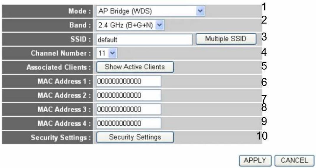
text_image
Mode : AP Bridge (WDS) Band : 2.4 GHz (B+G+N) SSID : default Multiple SSID Channel Number : 11 Associated Clients : Show Active Clients MAC Address 1 : 000000000000 MAC Address 2 : 000000000000 MAC Address 3 : 000000000000 MAC Address 4 : 000000000000 Security Settings : Security Settings 1 2 3 4 5 6 7 8 9 10 APPLY CANCELHere are descriptions of every setup items:
Band (2): Select the band you want to use, all the wireless routers must use the same setting.
SSID (3): Input the SSID of your wireless router, the setting should be the same with other wireless routers for the convenience of roaming.
Channel Number (4): Select the channel you want to use, all the wireless routers must use the same setting.
Associated Clients (5): Click 'Show Active Clients' button, then an "Active Wireless Client Table" will pop up. You can see the status of all active wireless stations that are connecting to the access point.
MAC address Input the MAC address of other wireless routers. 1 to 4 (6 - 9):
Security Setting (10): Click to set security settings for this connection (Please go to section '2-7-3 Wireless Security' for detailed instructions).
2.7.1.6. Setup Procedure for 'Universal Repeater'
In this mode, the router can act as a wireless repeater; it can be Station and AP at the same time. It can use Station function to connect to a Root AP and use AP function to service all wireless stations within its coverage.
NOTE: For Repeater Mode, this router will demodulate the received signal, checking if this signal is noise for the operating network then have the signal modulated and amplified again. The output power of this mode is the same as that of WDS and normal AP mode.
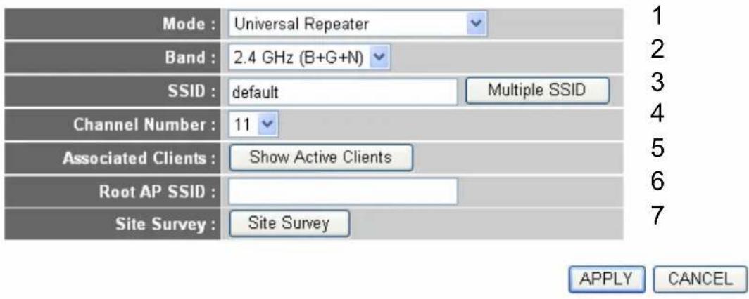
text_image
Mode : Universal Repeater Band : 2.4 GHz (B+G+N) SSID : default Multiple SSID Channel Number : 11 Associated Clients : Show Active Clients Root AP SSID : Site Survey : Site Survey 1 2 3 4 5 6 7 APPLY CANCELHere are descriptions of every setup items:
Band (2):
Select the band you want to use, all the wireless routers must use the same setting.
SSID (3): This is the name of wireless router. You can type any alphanumeric characters here, maximum 32 characters. SSID is used to identify your own wireless router from others when there are other wireless routers in the same area. Default SSID is 'default', it's recommended to change default ESSID value to the one which is meaningful to you, like myhome, office_room1, etc.
ChannelNumber (4): Select the channel you want to use, all the wireless clients must use the same setting.
Associated Clients (5): Click 'Show Active Clients' button, then an "Active Wireless Client Table" will pop up. You can see the status of all active wireless stations that are connecting to the access point.
Root AP SSID (6): In ‘Universal Repeater’ mode, this device can act as a station to connect to a Root AP. You should assign the SSID of the Root AP here or click ‘Select Site Survey’ button to choose a Root AP.
Site Survey (7): Click 'Select Site Survey' button, then a "Wireless Site Survey Table" will pop up. It will list all available access points near by. You can select one access point in the table and the router will join wireless LAN through this access point.
After you finish the wireless setting, please click 'Apply' button, after you click 'Apply', the following message will be displayed on your web browser:
Save settings successfully!
You may press CONTINUE button to continue configuring other settings or press APPLY button to restart the system to make the changes take effect.
CONTINUE
APPLY
Please click 'Continue' to back to previous setup menu; to continue on router setup, or click 'Apply' to reboot the router so the settings will take effect (Please wait for about 30 seconds while router is rebooting).
2.7.2. Advanced Wireless Settings
This router provides some advanced control of wireless parameters, if you want to configure these settings, please click 'Wireless' menu on the left of web management interface, then click 'Advanced Settings', and the following message will be displayed on your web browser:
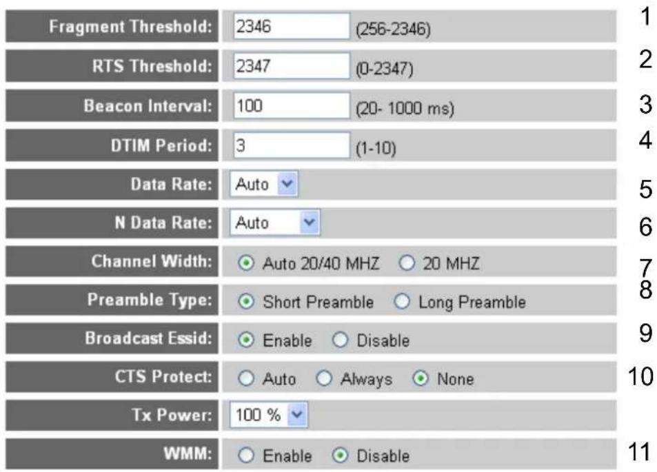

Here are descriptions of every setup items:
Fragment Threshold (1): Set the Fragment threshold of wireless radio. Do not modify default value if you don't know what it is, default value is 2346.
RTS Threshold (2): Set the RTS threshold of wireless radio. Do not modify default value if you don't know what it is, default value is 2347.
Beacon Interval (3): Set the beacon interval of wireless radio. Do not modify default value if you don't know what it is, default value is 100.
DTIM Period (4): Set the DTIM period of wireless radio. Do not modify default value if you don't know what it is, default value is 3.
Data Rate (5): Set the wireless data transfer rate to a certain value. Since most of wireless devices will negotiate with each other and pick a proper data transfer rate automatically, it's not necessary to change this value unless you know what will happen after modification.
N Data Rate (6): Same as above, but only for 802.11n clients.
Channel Width (7): Set channel width of wireless radio. Do not modify default value if you don't know what it is, default setting is 'Auto 20/40 MHz'.
Preamble Type (8): Set the type of preamble, do not modify default value if you don't know what it is, default setting is 'Short Preamble'.
Broadcast ESSID (9): Decide if the wireless router will broadcast its own ESSID or not. You can hide the ESSID of your wireless router (set the option to 'Disable'), so only people those who know the ESSID of your wireless router can get connected.
CTS Protect (10):
Enabling this setting will reduce the chance of radio signal collisions between 802.11b and 802.11g/n wireless access points. It's recommended to set this option to 'Auto' or 'Always'. However, if you set to 'None', your wireless router should be able to work fine, too.
WMM (11):
The short of Wi-Fi MultiMedia, it will enhance the data transfer performance of multimedia contents when they're being transferred over wireless network. If you don't know what it is / not sure if you need it, it's safe to set this option to 'Enable', however, default value is 'Disable'.
After you finish these wireless settings, please click 'Apply' button, button, and the following message will be displayed on your web browser:
Save settings successfully!
You may press CONTINUE button to continue configuring other settings or press APPLY button to restart the system to make the changes take effect.
CONTINUE
APPLY
Please click 'Continue' to back to previous setup menu; to continue on router setup, or click 'Apply' to reboot the router so the settings will take effect (Please wait for about 30 seconds while router is rebooting).
2.7.3. Wireless Security
It's very important to set wireless security settings properly! If you don't, hackers and malicious users can reach your network and valuable data without your consent and this will cause serious security problem.
To set wireless security settings, Please click 'Wireless' menu on the left of web management interface, then click 'Security Settings', then follow the following instructions to set wireless security settings:
Please select an encryption method from 'Encryption' dropdown menu, there are four options:
2.7.3.1. Disable Wireless Security
When you select this mode, data encryption is disabled, and every wireless device in proximity will be able to connect your wireless router if no other security measure is enabled (like MAC address access control - see section 2.7.4., or disable ESSID broadcast).
Only use this option when you really want to allow everyone to use your wireless router, and you don't care if there's someone reads the data you transfer over network without your consent.
2.7.3.2. WEP - Wired Equivalent Privacy
When you select this mode, the wireless router will use WEP encryption, and the following setup menu will be shown on your web browser:
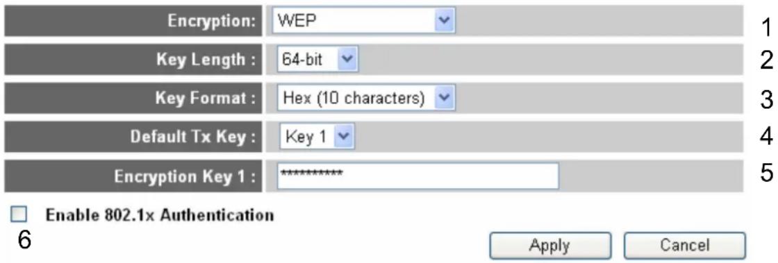
text_image
Encryption: WEP Key Length : 64-bit Key Format : Hex (10 characters) Default Tx Key : Key 1 Encryption Key 1 : ******** Enable 802.1x Authentication Apply CancelHere are descriptions of every setup items:
Key Length (2): There are two types of WEP key length: 64-bit and 128-bit. Using '128-bit' is safer than '64-bit', but will reduce some data transfer performance.
Key Format (3): There are two types of key format: ASCII and Hex. When you select a key format, the number of characters of key will be displayed. For example, if you select '64-bit' as key length, and 'Hex' as key format, you'll see the message at the right of 'Key Format' is 'Hex (10 characters), which means the length of WEP key is 10 characters.
Default Tx Key (4): You can set up to four sets of WEP key, and you can decide which key is being used by default here. If you don't know which one you should use, select 'Key 1'.
Encryption Key 1 (5): Input WEP key characters here, the number of characters must be the same as the number displayed at 'Key Format' field. You can use any alphanumerical characters (0-9, a-z, and A-Z) if you select 'ASCII' key format, and if you select 'Hex' as key format, you can use characters 0-9, a-f, and A-F. You must enter at least one encryption key here, and if you entered multiple WEP keys, they should not be same with each other.
Enable 802.1x IEEE 802.1x is an authentication protocol. Every
Authentication (6): user must use a valid account to login to this wireless router before accessing the wireless LAN. The authentication is processed by a RADIUS server. This mode only authenticates user by IEEE 802.1x, but it does not encryption the data during communication. If there is a RADIUS server in you environment, please enable this function. Check this box and another sub-menu will appear:
Enable 802.1x Authentication
| RADIUS Server IP address : | 7 | |
| RADIUS Server Port : | 1812 | 8 |
| RADIUS Server Password : | 9 |
RADIUS Server Please input the IP address of radius server here.
IP address (7):
RADIUS Server Please input the port number of radius server here.
Port (8):
RADIUS Server Please input the port number of radius password
Password (9): here.
TIPS: Some examples of WEP key
(Don't use those examples; use the one of your own!):
ASCII (5 characters): pilot phone 23561 2Hyux #@xml
ASCII (13 characters): digitalFAMILY 82Jh26xHy3m&n
Hex (10 characters): 287d2aa732 1152dabc85
Hex (26 characters): 9284bcda8427c9e036f7abcd84
To improve security level, do not use those words which can be found in a dictionary or too easy to remember! ('pilot' and 'phone' listed above are bad examples; just intended to show you how a WEP key look like). Wireless clients will remember the WEP key, so you only have to input the WEP key on wireless client once, and it's worth to use complicated WEP key to improve security level.
After you finish WEP setting, please click 'Apply' button and the following message will be displayed on your web browser:
Save settings successfully!
You may press CONTINUE button to continue configuring other settings or press APPLY button to restart the system to make the changes take effect.
CONTINUE
APPLY
Please click ‘Continue’ to back to previous setup menu; to continue on other setup procedures, or click ‘Apply’ to reboot the router so the settings will take effect (Please wait for about 30 seconds while router is rebooting).
2.7.3.3. Wi-Fi Protected Access (WPA)
When you select this mode, the wireless router will use WPA encryption, and the following setup menu will be shown on your web browser:
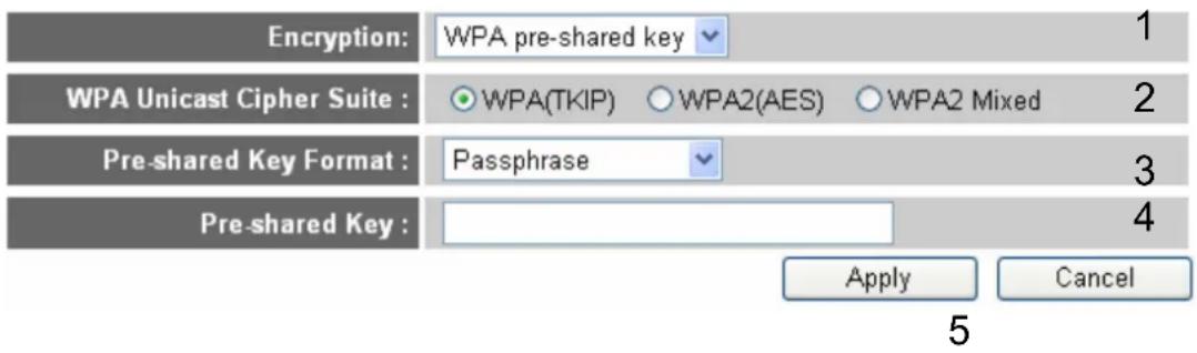
text_image
Encryption: WPA pre-shared key 1 WPA Unicast Cipher Suite : ○ WPA(TKIP) ○ WPA2(AES) ○ WPA2 Mixed 2 Pre-shared Key Format : Passphrase 3 Pre-shared Key : Apply Cancel 5Here are descriptions of every setup items:
WPA Unicast Please select a type of WPA cipher suite. Available
Cipher Suite (2): options are: WPA (TKIP), WPA2 (AES), and WPA2
Mixed. You can select one of them, but you have to make sure your wireless client support the cipher you selected.
Pre-shared Select the type of pre-shared key, you can select
Key Format (3): Passphrase (8 or more alphanumerical characters, up to 63), or Hex (64 characters of 0-9, and a-f).
Pre-shared Please input the WPA passphrase here.
Key (4): It's not recommended to use a word that can be found
in a dictionary due to security reason.
After you finish WPA Pre-shared key setting, please click 'Apply' button (5) and the following message will be displayed on your web browser:
Save settings successfully!
You may press CONTINUE button to continue configuring other settings or press APPLY button to restart the system to make the changes take effect.
CONTINUE
APPLY
Please click 'Continue' to back to previous setup menu; to continue on other setup procedures, or click 'Apply' to reboot the router so the settings will take effect (Please wait for about 30 seconds while router is rebooting).
NOTE: Some wireless clients (especially those manufactured before year 2003) only support WEP or WPA (TKIP) cipher. A driver upgrade would be needed for those clients to use WPA and WPA2 encryption.
2.7.3.4. WPA RADIUS
If you have a RADIUS server, this router can work with it and provide safer wireless authentication.
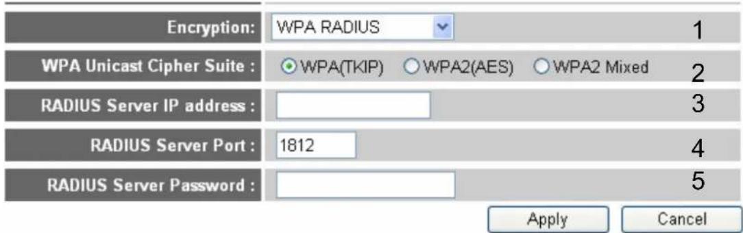
text_image
Encryption: WPA RADIUS 1 WPA Unicast Cipher Suite : ○WPA(TKIP) ○WPA2(AES) ○WPA2 Mixed 2 RADIUS Server IP address : RADIUS Server Port : 1812 4 RADIUS Server Password : Apply Cancel6
Here are descriptions of every setup items:
WPA Unicast Please select a type of WPA cipher suite. Available
Cipher Suite (2): options are: WPA (TKIP), WPA2 (AES), and WPA2
Mixed. You can select one of them, but you have to make sure your wireless client support the cipher you selected.
RADIUS Server Please input the IP address of your Radius
IP address (3): authentication server here.
RADIUS Server Please input the port number of your Radius
Port (4): authentication server here. Default setting is 1812.
RADIUS Server Please input the password of your Radius
Password (5): authentication server here.
After you finish with all settings, please click 'Apply' (6) button and the following message will be displayed on your web browser:
Save settings successfully!
You may press CONTINUE button to continue configuring other settings or press APPLY button to restart the system to make the changes take effect.
CONTINUE
APPLY
Please click ‘Continue’ to back to previous setup menu; to continue on other setup procedures, or click ‘Apply’ to reboot the router so the settings will take effect (Please wait for about 30 seconds while router is rebooting).
2.7.4. Wireless Access Control
This function will help you to prevent unauthorized users from connecting to your wireless router; only those wireless devices who have the MAC address you assigned here can gain access to your wireless router. You can use this function with other security measures described in previous section, to create a safer wireless environment.
Up to 20 MAC addresses can be assigned by using this function. Please click 'Wireless' menu on the left of web management interface, then click 'Access Control', and the following message will be displayed on your web browser:
• MAC Address Filtering Table
It allows to entry 20 sets address only.
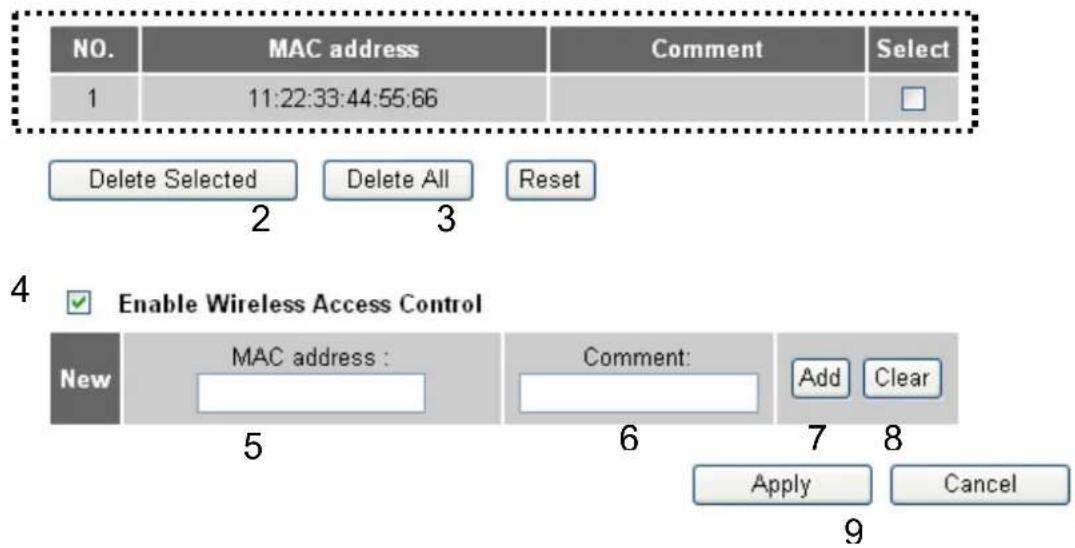
text_image
NO. MAC address Comment Select 1 11:22:33:44:55:66 Delete Selected Delete All Reset Enable Wireless Access Control New MAC address : Comment: Add Clear Apply Cancel 9All allowed MAC addresses will be displayed in 'MAC Address Filtering Table'
(1). Here are descriptions of every setup items:
Delete Selected (2): If you want to delete a specific MAC address entry, check the 'select' box of the MAC address you want to delete, then click 'Delete Selected' button. (You can select more than one MAC addresses).
Delete All (3): If you want to delete all MAC addresses listed here, please click 'Delete All' button.
Enable To enforce MAC address filtering,
Access Control (4): you have to check 'Enable Wireless Access Control'. When this item is unchecked, wireless router will not enforce MAC address filtering of wireless clients.
MAC Address (5): Input the MAC address of your wireless devices here, dash (-) or colon (:) are not required. (i.e. If the MAC address label of your wireless device indicates 'aa-bb-cc-dd-ee-ff' or 'aa:bb:cc:dd:ee:ff', just input 'aabbccddeeff'.
Comment (6): You can input any text here as the comment of this MAC address, like 'ROOM 2A Computer' or anything. You can input up to 16 alphanumeric characters here. This is optional and you can leave it blank, however, it's recommended to use this field to write a comment for every MAC addresses as a memory aid.
Add (7): Click 'Add' button to add the MAC address and associated comment to the MAC address filtering table.
Clear (8): Click 'Clear' to remove the value you inputted in MAC address and comment field.
After you finish with all settings, please click 'Apply' (9) button and the following message will be displayed on your web browser:
Save settings successfully!
You may press CONTINUE button to continue configuring other settings or press APPLY button to restart the system to make the changes take effect.
CONTINUE
APPLY
Please click 'Continue' to back to previous setup menu; to continue on other setup procedures, or click 'Apply' to reboot the router so the settings will take effect (Please wait for about 30 seconds while router is rebooting).
If you want to reset all settings in this page back to previously-saved value, please click 'Cancel' button.
2.7.5. Wi-Fi Protected Setup (WPS)
Wi-Fi Protected Setup (WPS) is the simplest way to build connection between wireless network clients and this wireless router. You don't have to select encryption mode and input a long encryption passphrase every time when you need to setup a wireless client, you only have to press a button on wireless client and this wireless router, and the WPS will do the rest for you.
This wireless router supports two types of WPS: Push-Button Configuration (PBC), and PIN code. If you want to use PBC, you have to push a specific button on the wireless client to start WPS mode, and switch this wireless router to WPS mode too. You can push Reset/WPS button of this wireless router, or click 'Start PBC' button in the web configuration interface to do this; if you want to use PIN code, you have to know the PIN code of wireless client and switch it to WPS mode, then provide the PIN code of the wireless client you wish to connect to this wireless router. The detailed instructions are listed follow:
Please click 'Wireless' menu on the left of web management interface, then click 'WPS', and the following message will be displayed on your web browser:
Enable WPS 1
2

text_image
WPS Information WPS Status : Unconfigured PinCode Self : 66571803 SSID : default Authentication Mode : Disable Passphrase Key : • Device Configure Configure by Push Button : Start PBC Configure by Client PinCode : Start PIN 3 4Here are descriptions of every setup items:
Enable WPS (1): Check this box to enable WPS function, uncheck it to disable WPS.
WPS Information (2): WPS-related system information will be displayed here:
WPS Status: If the wireless security (encryption) function of this wireless router is properly set, you'll see 'Configured' message here. If wireless security function has not been set, you'll see 'unConfigured'.
PinCode Self: This is the WPS PIN code of this wireless router. This code is useful when you need to build wireless connection by WPS with other WPS-enabled wireless devices.
SSID: The SSID of this wireless router will be displayed here.
Authentication Mode: The wireless security authentication mode of this wireless router will be displayed here. If you don't enable security function of the wireless router before WPS is activated, the router will auto set the security to WPA (AES) and generate a set of passphrase key for WPS connection.
Passphrase Key: The wireless security key of the will be displayed here.
Configure Click 'Start PBC' to start Push-Button style WPS
by Push Button (3): setup procedure. This wireless router will wait for WPS
requests from wireless clients for 2 minutes. The
'WLAN' LED on the wireless router will be steady on for
2 minutes when this wireless router is waiting for
incoming WPS request.
Configure by Please input the PIN code of the wireless client you
client PinCode (4): wish to connect, and click 'Start PIN' button. The
'WLAN' LED on the wireless router will be steady on
when this wireless router is waiting for incoming WPS
request.
2.7.6. Security Tips for Wireless Network
Here are some quick tips to help you improve the security level of your wireless network:
Never use simple words (like school, apple and computer) as WEP encryption or WPA passphrase.
A complicated (the combination of number, alphabet, even symbol, and long enough) WEP key and WPA passphrase is much safer than simple and short ones. Remember that the wireless client is capable to keep the key or passphrase for you, so you only have to input the complicated key or passphrase once. It's not too trouble but will greatly improve security level.
You can hide the ESSID of this router by set ‘Broadcast ESSID’ option to ‘Disable’. Your wireless router will not be found by other people in proximity if they’re just using the AP scanning function of their wireless client, and this can reduce the chance of being intruded.
Use ‘Access Control’ function described in section 2.7.4., so those people who are not in your list will not be able to connect to your network.
3
Advanced Functions
3.1. Configuration Utility
Quality of Service (QoS)
Quality of service provides an efficient way for computers on the network to share the internet bandwidth with a promised quality of internet service.
Without QoS, all computers and devices on the network will compete with each other to get internet bandwidth, and some applications which require guaranteed bandwidth (like video streaming and network telephone) will be affected, therefore an unpleasing result will occur, like the interruption of video / audio transfer.
With this function, you can limit the maximum bandwidth or give a guaranteed bandwidth for a specific computer, to avoid said unpleasing result from happening.
3.1.1.BasicQoSSettings
Please follow the following instructions to set QoS parameters:
Please click 'Qos' menu on the left of web management interface and the following message will be displayed on your web browser:
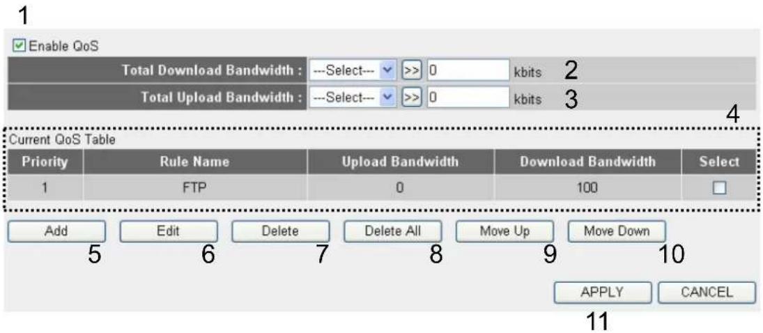
text_image
Enable QoS Total Download Bandwidth : ---Select--- >> 0 kbits 2 Total Upload Bandwidth : ---Select--- >> 0 kbits 3 Current QoS Table Priority Rule Name Upload Bandwidth Download Bandwidth Select 1 FTP 0 100 Add Edit Delete Delete All Move Up Move Down 5 6 7 8 9 10 APPLY CANCEL 11Here are descriptions of every setting:
Enable QoS (1): Check this box to enable QoS function, unselect this box if you don't want to enforce QoS bandwidth limitations.
Total Download You can set the limit of total download bandwidth in Bandwidth (2): kbits. To disable download bandwidth limitation, input '0' here.
Total Upload You can set the limit of total upload bandwidth in kbits. Bandwidth (3): To disable upload bandwidth limitation, input '0' here.
Current QoS All existing QoS rules will be displayed here. Table (4):
Add (5): Click 'add' button to add a new QoS rule, see section
3-1-2 'Add a new QoS rule' below.
Edit (6): If you want to modify the content of a specific rule,
please check the 'select' box of the rule you want to edit, then click 'Edit' button. Only one rule should be selected a time! If you didn't select a rule before clicking 'Edit' button, you'll be prompted to add a new rule.
Delete (7): You can delete selected rules by clicking this button.
You can select one or more rules to delete by check the 'select' the box of the rule(s) you want to delete a time. If the QoS table is empty, this button will be grayed out and can not be clicked.
Delete All (8): By clicking this button, you can delete all rules currently
in the QoS table. If the QoS table is empty, this button will be grayed out and can not be clicked.
Move Up (9): You can pull up the priority of the QoS rule you selected
by clicking this button.
Move Down (10): You can lower the priority of the QoS rule you selected
by clicking this button.
After you finish with all settings, please click 'Apply' (11) button and the
following message will be displayed on your web browser:
Save settings successfully!
You may press CONTINUE button to continue configuring other settings or press APPLY button to restart the system to make the changes take effect.
CONTINUE
APPLY
Please click 'Continue' to back to previous setup menu; to continue on other setup procedures, or click 'Apply' to reboot the router so the settings will take effect (Please wait for about 30 seconds while router is rebooting).
If you want to reset all settings in this page back to previously-saved value, please click 'Cancel' button.
3.1.2. Add a New QoS Rule
After you click 'Add' button in QoS menu, the following message will appear:
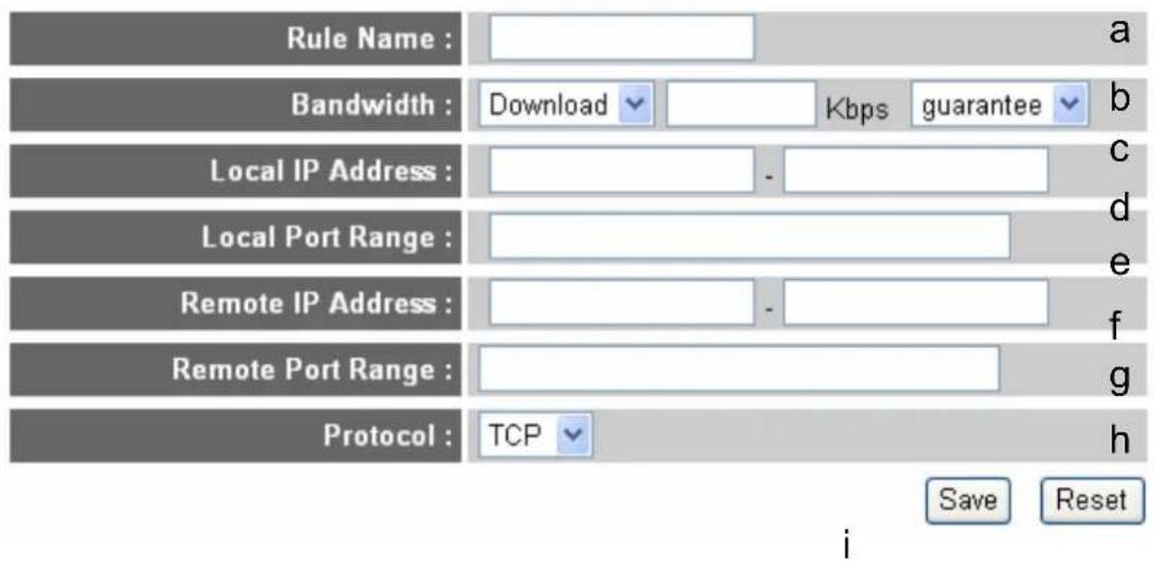
text_image
Rule Name : Bandwidth : Download Kbps guarantee Local IP Address : Local Port Range : Remote IP Address : Remote Port Range : Protocol : TCP Save Reset iHere are descriptions of every setup items:
Rule Name (a): Please give a name to this QoS rule (up to 15 alphanumerical characters)
Bandwidth (b): Set the bandwidth limitation of this QoS rule. You have to select the data direction of this rule (Upload of Download), and the speed of bandwidth limitation in Kbps, then select the type of QoS: 'guarantee' (guaranteed usable bandwidth for this rule) or 'max' (set the maximum bandwidth for the application allowed by this rule).
Local IP Address (c): Specify the local (source) IP address that will be affected by this rule. Please input the starting IP address in the left field, and input the end IP address in the right field to define a range of IP addresses, or just input the IP address in the left field to define a single IP address.
Local Port Range (d): Please input the range of local (source) port number that will be affected by this rule. If you want to apply this rule on port 80 to 90, please input '80-90'; if you want to apply this rule on a single port, just input the port number, like '80'.
Remote IP Specify the remote (destination) IP address
Address (e): that will be affected by this rule. Please input the starting IP address in the left field, and input the end IP address in the right field to define a range of IP addresses, or just input the IP address in the left field to define a single IP address.
Remote Port Please input the range of remote (destination)
Range (f): port number that will be affected by this rule. If you want to apply this rule on port 80 to 90, please input '80-90'; if you want to apply this rule on a single port, just input the port number, like '80'. If the remote (destination) IP address and /or port number is universal, just leave it blank.
Traffic Type (g): Please select the traffic type of this rule, available options are None, SMTP, HTTP, POP3, and FTP. You can select a specific traffic type for this rule, if you want to make this rule as a IP address based rule (apply the limitation on all traffics from / to the specified IP address / port number), select 'None'.
Protocol (h): Please select the protocol type of this rule, available options are TCP and UDP. If you don't know what protocol your application uses, please try 'TCP' first, and switch to 'UDP' if this rule doesn't seems to work.
After you finish with all settings, please click 'save' button (i), you'll be brought back to previous menu, and the rule you just set will appear in current QoS table; if you did anything wrong, you'll get an error message when you click 'Save' button, please correct your input by the instructions given by the error message.
If you want to erase all values you just entered. Click 'Reset'
3.2. Network Address Translation (NAT)
Network address translations solve the problem if sharing a single IP address to multiple computers. Without NAT, all computers must be assigned with a valid Internet IP address to get connected to Internet, but Internet service providers only provide very few IP addresses to every user. Therefore it's necessary to use NAT technology to share a single Internet IP address to multiple computers on local network, so everyone can get connected to Internet.
Please follow the following instructions to set NAT parameters:
3.2.1. Basic NAT Settings (Enable or Disable NAT Function)
Please click 'NAT' menu on the left of web management interface, and the following message will be displayed on your web browser:
NAT Settings
Network Address Translation (NAT) allows multiple users at your local site to access the Internet through a single Public IP Address or multiple Public IP Addresses. NAT provides Firewall protection from hacker attacks and has the flexibility to allow you to map Private IP Addresses to Public IP Addresses for key services such as the Web or FTP.
1 Enable or disable NAT module function : ☐ Enable ○ Disable
2
Apply
To enable NAT function, please select 'Enable' for 'Enable NAT module function' (1); to disable, please select 'Disable'.
After you made the selection, please click 'Apply' button (2) and the following message will be displayed on your web browser:
Save settings successfully!
You may press CONTINUE button to continue configuring other settings or press APPLY button to restart the system to make the changes take effect.
CONTINUE
APPLY
Please click 'Continue' to back to previous setup menu; to continue on other setup procedures, or click 'Apply' to reboot the router so the settings will take effect (Please wait for about 30 seconds while router is rebooting).
3.2.2. PortForwarding
This function allows you to redirect a single port or consecutive ports of Internet IP address to the same port of the IP address on local network. The port number(s) of Internet IP address and private IP address (the IP address on local network) must be the same. If the port number of Internet IP address and private IP address is different, please use 'Virtual Server' function, described in next section.
Please click 'NAT' menu on the left of web management interface, then click 'Port Forwarding', and the following message will be displayed on your web browser:
1
□ Enable Port Forwarding
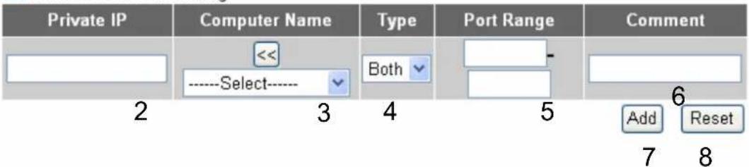
text_image
Private IP Computer Name Type Port Range Comment << Both Add Reset 2 3 4 5 6 7 8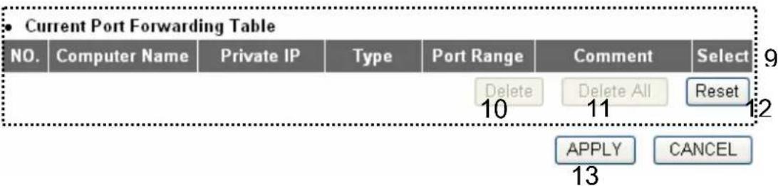
text_image
• Current Port Forwarding Table NO. Computer Name Private IP Type Port Range Comment Select Delete Delete All Reset 10 11 12 APPLY CANCEL 13Here are descriptions of every setup items:
Enable Port Check this box to enable port mapping, and uncheck
Forwarding (1): this box to disable port mapping.
Private IP (2): Input the IP address of the computer on local network which provides internet service.
Computer Name (3): Pull down the menu and all the computers connected to the router will be listed here. You can easily to select the computer name without checking the IP address of the computer.
Type (4): Select the type of connection, TCP or UDP. If you're not sure, please select 'Both'.
Port Range (5): Input the starting port number in the left field, and input the ending port number in the right field. If you only want to redirect a single port number, just fill the port number in the left field.
Comment (6): Please input any text to describe this mapping, up to 16 alphanumeric characters.
Add (7): Add the mapping to port forwarding table.
Reset (8): Remove all inputted values.
Port Forwarding All existing port forwarding mappings will
Table (9): be displayed here.
Delete (10): Please select a port forwarding mapping by clicking the 'Select' box of the mapping, then click 'Delete Selected' button to remove the mapping. If there's no existing mapping, this button will be grayed out.
Delete All (11): Delete all mappings existed in virtual server table.
Reset (12): Unselect all mappings.
After you finish with all settings, please click 'Apply' (13) button and the following message will be displayed on your web browser:
Save settings successfully!
You may press CONTINUE button to continue configuring other settings or press APPLY button to restart the system to make the changes take effect.
CONTINUE
APPLY
Please click 'Continue' to back to previous setup menu; to continue on other setup procedures, or click 'Apply' to reboot the router so the settings will take effect (Please wait for about 30 seconds while router is rebooting).
If you want to reset all settings in this page back to previously-saved value, please click 'Cancel' button.
3.2.3. VirtualServer
This function allows you to redirect a port on Internet IP address (on WAN port) to a specified port of an IP address on local network, so you can setup an Internet service on the computer on local network, without exposing it on Internet directly. You can also build many sets of port redirection, to provide many different Internet services on different local computers via a single Internet IP address.
Please click 'NAT' menu on the left of web management interface, then click 'Virtual Server', and the following message will be displayed on your web browser:
1
□ Enable Virtual Server
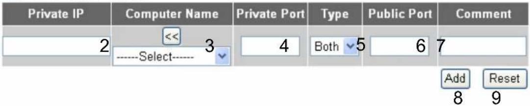
text_image
Private IP 2 << 3 ----Select---- Private Port 4 Both 5 6 7 Add Reset 8 9
flowchart
graph LR
    A["NO."] --> B["Computer Name"]
    B --> C["Private IP"]
    C --> D["Private Port"]
    D --> E["Type"]
    E --> F["Public Port"]
    F --> G["Delete"]
    F --> H["Delete All"]
    F --> I["Reset"]
    E --> J["11"]
    J --> K["12"]
    K --> L["13"]
    L --> M["APPLY"]
    L --> N["CANCEL"]
    M --> O["14"]
Here are descriptions of every setup items:
Enable Virtual Check this box to enable virtual server, and uncheck
Server (1): this box to disable virtual server.
Private IP (2): Input the IP address of the computer which provides Internet service.
Computer Name (3): Pull down the menu and all the computers connected to the router will be listed here. You can easily to select the computer name without checking the IP address of the computer.
Private Port (4): Input the port number of the IP address which provides Internet service.
Type (5): Select the type of connection, TCP or UDP. If you're not sure, please select 'Both'.
Public Port (6): Please select the port number of Internet IP address which will be redirected to the port number of local IP address defined above.
Comment (7): Please input any text to describe this mapping, up to 16 alphanumeric characters.
Add (8): Add the mapping to virtual server table.
Reset (9): Remove all inputted values.
Virtual Server All existing virtual server mappings will be displayed
Table (10): here.
Delete (11): Please select a virtual server mapping by clicking the
'Select' box of the mapping, then click 'Delete Selected' button to remove the mapping. If there's no existing mapping, this button will be grayed out.
Delete All (12): Delete all mappings existed in virtual server table.
Reset (13): Unselect all mappings.
After you finish with all settings, please click 'Apply' (14) button and the following message will be displayed on your web browser:
Save settings successfully!
You may press CONTINUE button to continue configuring other settings or press APPLY button to restart the system to make the changes take effect.
CONTINUE
APPLY
Please click 'Continue' to back to previous setup menu; to continue on other setup procedures, or click 'Apply' to reboot the router so the settings will take effect (Please wait for about 30 seconds while router is rebooting).
If you want to reset all settings in this page back to previously-saved value, please click 'Cancel' button.
3.2.4. Port Mapping for Special Applications
Some applications require more than one connection a time; these applications won't work with simple NAT rules. In order to make these applications work, you can use this function to let these applications work.
1 Enable Special Applications
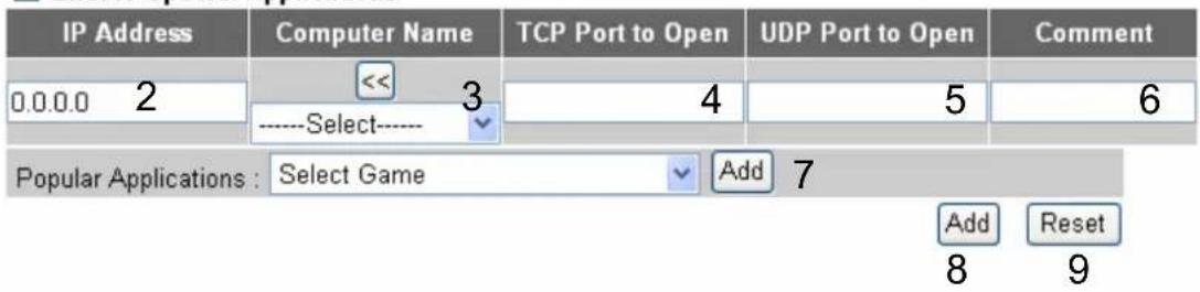
text_image
IP Address 0.0.0.0 2 << 3 ----Select---- 4 5 6 Popular Applications : Select Game Add 7 Add Reset 8 9- Current Trigger-Port Table

text_image
NO. Computer Name IP Address TCP Port to Open UDP Port to Open Comment Select Delete Delete All Reset 11 12 13 APPLY CANCEL14
Here are descriptions of every setup items:
Enable (1): Check this box to enable special applications and uncheck this box to disable virtual server.
IP Address (2): Input the IP address of the computer which you want to open the ports.
Computer Name (3): Pull down the menu and all the computers connected to the router will be listed here. You can easily to select the computer name without checking the IP address of the computer.
TCP Port to Open (4): This is the out going (Outbound) range of TCP port numbers for this particular application.
UDP Port to Open (5): This is the out going (Outbound) range of UDP port numbers for this particular application.
Comment (6): The description of this setting.
Popula This section lists the more popular applications that Applications (7): require multiple connections. Select an application from the Popular Applications selection and click 'Add' to save the setting to 'Current Trigger-Port Table.'
Add (8): Add the setting to the 'Current Trigger-Port Table.'
Reset (9): Click 'Reset' will clear all above setting and you can set up again.
Current All the settings for the special applications will be
Trigger-Port (10): listed here. If you want to remove some Special Application settings from the "Current Trigger-Port Table", select the Special Application settings you want to remove in the table and then click "Delete Selected". If you want remove all Special Application settings from the table, just click "Delete All" button. Click "Reset" will clear your current selections.
Delete (11): Please select a special application by clicking the 'Select' box of the mapping, then click 'Delete Selected' button to remove the setting. If there's no setting here, this button will be grayed out.
Delete All (12): Delete all settings existed in trigger port table.
Reset (13): Unselect all settings.
Note: Only one LAN client can use a particular special application at a time.
After you finish with all settings, please click 'Apply' (14) button and the following message will be displayed on your web browser:
Save settings successfully!
You may press CONTINUE button to continue configuring other settings or press APPLY button to restart the system to make the changes take effect.
CONTINUE
APPLY
Please click 'Continue' to back to previous setup menu; to continue on other setup procedures, or click 'Apply' to reboot the router so the settings will take effect (Please wait for about 30 seconds while the router is rebooting).
If you want to reset all settings in this page back to previously-saved value, please click 'Cancel' button.
3.2.5. UPnP Setting
This function enables network auto-configuration for peer-to-peer communications, with this function, network devices will be able to communicate with other devices directly, and learn about information about other devices. Many network device and applications rely on UPnP function nowadays.
Please click ‘NAT’ menu on the left of web management interface, then click ‘UPnP’, and the following message will be displayed on your web browser:
UPnP Feature:

Enable

Disable
Apply
Cancel
There is only one option in this page, please select 'Enable' or 'Disable' to enable or disable UPnP function, then click 'Apply' button, and the following message will be displayed on your web browser:
Save settings successfully!
You may press CONTINUE button to continue configuring other settings or press APPLY button to restart the system to make the changes take effect.
CONTINUE
APPLY
Please click 'Continue' to back to previous setup menu; to continue on other setup procedures, or click 'Apply' to reboot the router so the settings will take effect (Please wait for about 30 seconds while router is rebooting).
If you want to reset all settings in this page back to previously-saved value, please click 'Cancel' button.
3.2.6.ALGSettings
Application Layer Gateway (ALG) is a special function of this router. It includes many preset routing rules for numerous applications which require special support. With these supports, those applications which required special support will be able to work with NAT architecture.
Please click 'NAT' menu on the left of web management interface, then click 'ALG Settings', and the following message will be displayed on your web browser:
| Enable | Name | Comment |
| Amanda | Support for Amanda backup tool protocol. | |
| Egg | Support for eggdrop bot networks. | |
| FTP | Support for FTP. | |
| H323 | Support for H323/netmeeting. | |
| IRC | Allows DCC to work though NAT and connection tracking. | |
| MMS | Support for Microsoft Streaming Media Services protocol. | |
| Quake3 | Support for Quake III Arena connection tracking and nat. | |
| Talk | Allows netfilter to track talk connections. | |
| TFTP | Support for TFTP. | |
| IPsec | Support for IPsec passthrough | |
| Starcraft | Support for Starcraft/Battle.net game protocol. | |
| MSN | Support for MSN file tranfer. | |
| RTSP | Support for RTSP. | |
| PPTP | Support for PPTP passthrough. | |
| IGMP | IGMP proxy. |
| Apply | Cancel |
There are many applications listed here. Please check the box of the special support for applications you need, and then click 'Apply' button and the following message will be displayed on your web browser:
Save settings successfully!
You may press CONTINUE button to continue configuring other settings or press APPLY button to restart the system to make the changes take effect.
CONTINUE
APPLY
Please click 'Continue' to back to previous setup menu; to continue on other setup procedures, or click 'Apply' to reboot the router so the settings will take effect (Please wait for about 30 seconds while router is rebooting).
If you want to reset all settings in this page back to previously-saved value, please click 'Cancel' button.
3.3. Firewall
Excepting NAT, this router also provides firewall function to block malicious intruders from accessing your computers on local network. These functions include inbound attack prevention, and block outbound traffics, like block URLs which have pre-defined keywords.
Please follow the following instructions to enable or disable firewall function:
Please click 'Firewall' menu on the left of web management interface, and the following message will be displayed on your web browser:
Security Settings (Firewall)
The Broadband router provides extensive firewall protection by restricting connection parameters, thus limiting the risk of hacker attack, and defending against a wide array of common attacks. However, for applications that require unrestricted access to the Internet, you can configure a specific client/server as a Demilitarized Zone (DMZ).
Enable or disable Firewall module function ☐ Enable ☑ Disable
Apply
Please select 'Enable' or 'Disable' to enable or disable firewall function of this router, the click 'Apply' button, and the following message will be displayed on your web browser:
Save settings successfully!
You may press CONTINUE button to continue configuring other settings or press APPLY button to restart the system to make the changes take effect.
CONTINUE
APPLY
Please click 'Continue' to back to previous setup menu; to continue on other setup procedures, or click 'Apply' to reboot the router so the settings will take effect (Please wait for about 30 seconds while router is rebooting).
3.3.1. AccessControl
This function allows or denies computers with specific MAC address from connecting to the network; it can also allow or deny computers with specific IP address, protocol, or port.
Please click 'Firewall' menu on the left of web management interface, then click 'Access Control', and the following message will be displayed on your web browser:
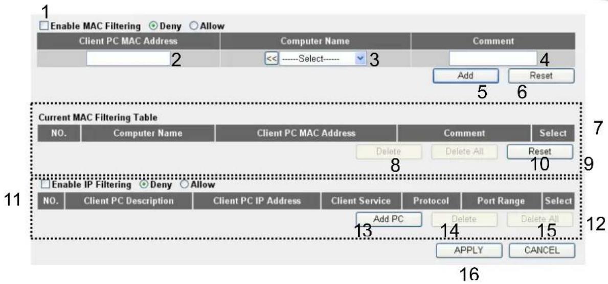
text_image
Enable MAC Filtering Deny Allow Client PC MAC Address Computer Name Comment 2 <<----Select---- 3 Add Reset 5 6 Current MAC Filtering Table NO. Computer Name Client PC MAC Address Comment Select Delete Delete All Reset 8 10 Enable IP Filtering Deny Allow NO. Client PC Description Client PC IP Address Client Service Protocol Port Range Select Add PC Delete Delete All 13 14 15 APPLY CANCEL 16Here are descriptions of every setup items:
Enable MAC Check this box to enable MAC address based
Filtering (1): filtering, and please select 'Deny' or 'Allow' to decide
the behavior of MAC filtering table. If you select deny, all MAC addresses listed in filtering table will be denied from connecting to the network; if you select allow, only MAC addresses listed in filtering table will be able to connect to the network, and rejecting all other network devices.
Client PC Please input the MAC address of computer or network
MAC address (2): device here, dash (-) or colon (:) are not required. (i.e. If the MAC address label of your wireless device indicates 'aa-bb-cc-dd-ee-ff' or 'aa:bb:cc:dd:ee:ff', just input 'aabbccddeeff'
Computer Name (3): Pull down the menu and all the computers connected to the router will be listed here. You can easily to select the computer name without checking the IP address of the computer.
Comment (4): You can input any text here as the comment of this MAC address, like 'ROOM 2A Computer' or anything. You can input up to 16 alphanumeric characters here. This is optional and you can leave it blank, however, it's recommended to use this field to write a comment for every MAC addresses as a memory aid.
Add (5): Click 'Add' button to add the MAC address and associated comment to the MAC address filtering table.
Reset (6): Remove all inputted values.
Current MAC All existing MAC addresses in filtering table
Filtering Table (7): will be listed here.
Delete (8): If you want to delete a specific MAC address entry, check the 'select' box of the MAC address you want to delete, then click 'Delete Selected' button. (You can select more than one MAC addresses).
Delete All (9): If you want to delete all MAC addresses listed here, please click 'Delete All' button.
Reset (10): You can also click 'Reset' button to unselect all MAC addresses.
Enable IP Check this box to enable IP address based
Filtering (11): filtering, and please select 'Deny' or 'Allow' to decide the behavior of IP filtering table. If you select deny, all IP addresses listed in filtering table will be denied from connecting to the network; if you select allow, only IP addresses listed in filtering table will be able to connect to the network, and rejecting all other network devices.
IP Filtering Table (12): All existing IP addresses in filtering table will be listed here.
Add PC (13): Click this button to add a new IP address to IP filtering table, up to 20 IP addresses can be added. Please refer to section 3.3.1.1. 'Add PC' below.
Delete (14): If you want to delete a specific IP address entry, check the 'select' box of the IP address you want to delete, then click 'Delete Selected' button. (You can select more than one IP addresses).
Delete All (15): If you want to delete all IP addresses listed here, please click 'Delete All' button.
After you finish with all settings, please click 'Apply' (16) button and the following message will be displayed on your web browser:
Save settings successfully!
You may press CONTINUE button to continue configuring other settings or press APPLY button to restart the system to make the changes take effect.
CONTINUE
APPLY
Please click 'Continue' to back to previous setup menu; to continue on other setup procedures, or click 'Apply' to reboot the router so the settings will take effect (Please wait for about 30 seconds while router is rebooting).
If you want to reset all settings in this page back to previously-saved value, please click 'Cancel' button.
3.3.1.1. Add PC
After button is clicked, the following message will be displayed on your web browser:

text_image
Client PC Description : Client PC IP address :Client PC Service :
| Service Name | Detail Description | Select |
| WWW | HTTP, TCP Port 80, 3128, 8000, 8080, 8081 | |
| E-mail Sending | SMTP, TCP Port 25 | |
| News Forums | NNTP, TCP Port 119 | |
| E-mail Receiving | POP3, TCP Port 110 | |
| Secure HTTP | HTTPS, TCP Port 443 | |
| File Transfer | FTP, TCP Port 21 | |
| MSN Messenger | TCP Port 1863 | |
| Telnet Service | TCP Port 23 | |
| AIM | AOL Instant Messenger, TCP Port 5190 | |
| NetMeeting | H.323, TCP Port 389,522,1503,1720,1731 | |
| DNS | UDP Port 53 | |
| SNMP | UDP Port 161, 162 | |
| VPN-PPTP | TCP Port 1723 | |
| VPN-L2TP | UDP Port 1701 | |
| TCP | All TCP Port | |
| UDP | All UDP Port |
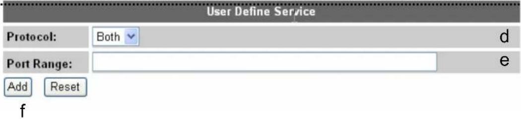
text_image
User Define Service Protocol: Both d Port Range: Add Reset fC
Here are descriptions of every setup items:
Client PC Please input any text to describe this IP address, up to
Description (a): 16 alphanumerical characters.
Client PC IP Please input the starting IP address in the left field, and
address (b): input the end IP address in the right field to define a
range of IP addresses, or just input the IP address in the left field to define a single IP address.
Client PC Please check all services you want to allow or deny this
Service (c): IP address to use, you can check multiple services.
Protocol (d): If the service you need is not listed above, you can
create a new service on your own. Please select TCP or UDP, if you're not sure, please select 'Both'.
Port Range (e): Please input the port range of new service here. If you
want to specify port 80 to 90, please input '80-90'; if you want to apply this rule on a single port, just input the port number, like '80'.
Add (f): When you finish with all settings, please click 'Add' to
save settings, you'll be brought back to previous menu, and the rule you just set will appear in current IP filtering table.
If you want to remove all settings in this page, click 'Reset' button.
3.3.2. URLBlocking
If you want to prevent computers in local network from accessing certain website (like pornography, violence, or anything you want to block), you can use this function to stop computers in local network from accessing the site you defined here.
This function is useful for parents and company managers.
Please follow the following instructions to set URL blocking parameters:
Please click ‘Firewall’ menu on the left of web management interface, then click ‘URL Blocking’, and the following message will be displayed on your web browser:
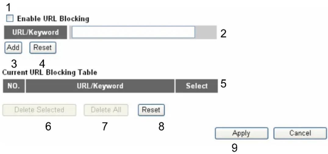
flowchart
graph TD
    A["Enable URL Blocking"] --> B["URL/Keyword"]
    B --> C["Add"]
    B --> D["Reset"]
    E["Current URL Blocking Table"] --> F["NO."]
    F --> G["Delete Selected"]
    F --> H["Delete All"]
    F --> I["Reset"]
    I --> J["Apply"]
    I --> K["Cancel"]
Here are descriptions of every setup items:
Enable URL Check this box to enforce URL Blocking, uncheck it to Blocking (1): disable URL Blocking.
URL/Keyword (2): Input the URL (host name or IP address of website, like http://www.blocked-site.com or http://11.22.33.44), or the keyword which is contained in URL (like pornography, cartoon, stock, or anything).
Add (3): Click 'Add' button to add the URL / keyword to the URL / Keyword filtering table.
Reset (4): Click 'Reset' to remove the value you inputted in URL/Keyword field.
Current URL All existing URL/Keywords in filtering table will be listed Blocking Table (5): here.
Delete (6): If you want to delete a specific URL/Keyword entry, check the 'select' box of the MAC address you want to delete, then click 'Delete Selected' button. (You can select more than one MAC addresses).
Delete All (7): If you want to delete all URL/Keyword listed here, please click 'Delete All' button.
Reset (8): You can also click 'Reset' button to unselect all URL/Keywords.
After you finish with all settings, please click 'Apply' (9) button and the following message will be displayed on your web browser:
Save settings successfully!
You may press CONTINUE button to continue configuring other settings or press APPLY button to restart the system to make the changes take effect.
CONTINUE
APPLY
Please click 'Continue' to back to previous setup menu; to continue on other setup procedures, or click 'Apply' to reboot the router so the settings will take effect (Please wait for about 30 seconds while router is rebooting).
If you want to reset all settings in this page back to previously-saved value, please click 'Cancel' button.
3.3.3.DoSAttackPrevention
Denial of Service (DoS) is a common attack measure, by transmitting a great amount of data or request to your Internet IP address and server, the Internet connection will become very slow, and server may stop responding because it is not capable to handle too much traffics.
This router has a built-in DoS attack prevention mechanism; when you activate it, the router will stop the DoS attack for you.
Please follow the following instructions to set DoS prevention parameters:
Please click 'Firewall' menu on the left of web management interface, then click 'DoS', and the following message will be displayed on your web browser:
Denial of Service Feature
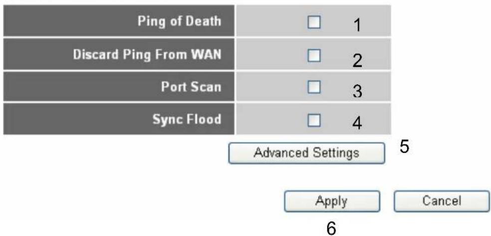
flowchart
graph TD
    A["Ping of Death"] --> B["1"]
    C["Discard Ping From WAN"] --> D["2"]
    E["Port Scan"] --> F["3"]
    G["Sync Flood"] --> H["4"]
    I["Advanced Settings"] --> J["Apply"]
    K["Cancel"] --> L["6"]
Here are descriptions of every setup items:
Ping of Death (1): Ping of Death is a special packet, and it will cause certain computer to stop responding. Check this box and the router will filter this kind of packet out.
Discard Ping Ping is a common and useful tool to know the From WAN (2): connection status of a specified remote network device, but some malicious intruder will try to fill your network bandwidth with a lot of PING request data packet, to make your internet connection become very slow, even unusable. Check this box and the router will ignore all inbound PING request, but when you activate this function, you will not be able to ping your own router from internet, too.
Port Scan (3): Some malicious intruder will try to use a ‘port scanner’ to know how many ports of your Internet IP address are open, and they can collect a lot of valuable information by doing so. Check this box and the router will block all traffics which are trying to scan your Internet IP address.
Sync Flood (4): This is another kind of attack, which uses a lot of fake connection request to consume the memory of your server, and try to make your server become unusable. Check this box and the router will filter this kind of traffic out.
Advanced Click this button and you can set advanced settings of Settings (5): the DoS prevention method listed above, please see section 3-3-3-1 'DoS – Advanced Settings' below.
After you finish with all settings, please click 'Apply' (6) button and the following message will be displayed on your web browser:
Save settings successfully!
You may press CONTINUE button to continue configuring other settings or press APPLY button to restart the system to make the changes take effect.
CONTINUE
APPLY
Please click ‘Continue’ to back to previous setup menu; to continue on other setup procedures, or click ‘Apply’ to reboot the router so the settings will take effect (Please wait for about 30 seconds while router is rebooting).
If you want to reset all settings in this page back to previously-saved value, please click 'Cancel' button.
3.3.3.1. DoS - Advanced Settings
When you click 'Advanced' button in DoS menu, the following message will be displayed on your web browser:
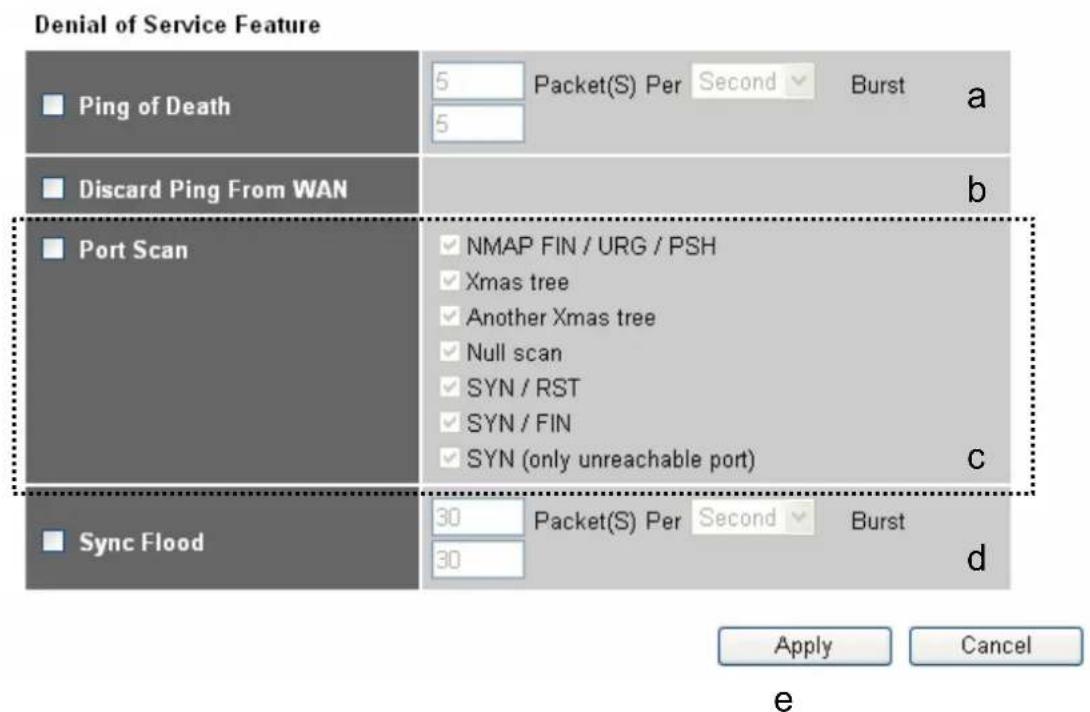
text_image
Denial of Service Feature Ping of Death 5 Packet(S) Per Second Burst a 5 Discard Ping From WAN b Port Scan ✓ NMAP FIN / URG / PSH ✓ Xmas tree ✓ Another Xmas tree ✓ Null scan ✓ SYN / RST ✓ SYN / FIN ✓ SYN (only unreachable port) c Sync Flood 30 Packet(S) Per Second Burst d 30 Apply Cancel eHere are descriptions of every setup items:
Ping of Death (a): Set the threshold of when this DoS prevention mechanism will be activated. Please check the box of Ping of Death, and input the frequency of threshold (how many packets per second, minute, or hour), you can also input the 'Burst' value, which means when this number of 'Ping of Death' packet is received in very short time, this DoS prevention mechanism will be activated.
Discard Ping Check the box to activate this DoS prevention From WAN (b): mechanism.
Port Scan (c): Many kind of port scan methods are listed here, please check one or more DoS attack methods you want to prevent.
Sync Flood (d): Like Ping of Death, you can set the threshold of when this DoS prevention mechanism will be activated.
After you finish with all settings, please click 'Apply' (e) button and the following message will be displayed on your web browser:
Save settings successfully!
You may press CONTINUE button to continue configuring other settings or press APPLY button to restart the system to make the changes take effect.
CONTINUE
APPLY
Please click 'Continue' to back to previous setup menu; to continue on other setup procedures, or click 'Apply' to reboot the router so the settings will take effect (Please wait for about 30 seconds while router is rebooting).
If you want to reset all settings in this page back to previously-saved value, please click 'Cancel' button.
3.3.4. Demilitarized Zone (DMZ)
Demilitarized Zone (DMZ) refers to a special area in your local network. This area resides in local network, and all computers in this area uses private IP address, too. But these private IP addresses are mapped to a certain Internet IP address, so other people on Internet can fully access those computers in DMZ.
Please follow the following instructions to set DMZ parameters:
Please click 'Firewall' menu on the left of web management interface, then click 'DMZ', and the following message will be displayed on your web browser:
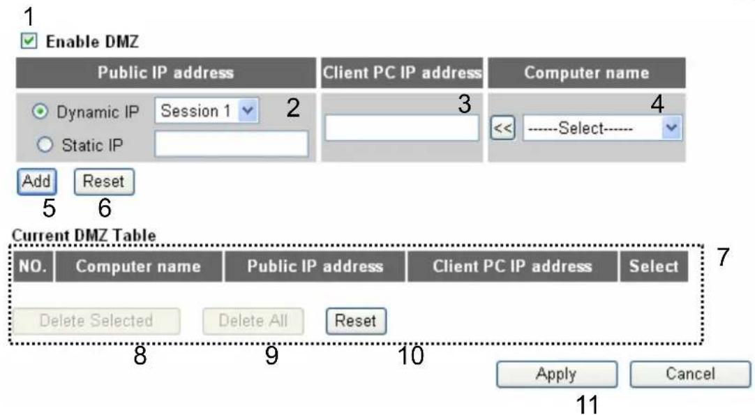
text_image
Enable DMZ Public IP address Dynamic IP Session 1 Static IP Add Reset 5 6 Client PC IP address 3 << Select---- 4 Current DMZ Table NO. Computer name Public IP address Client PC IP address Select Delete Selected Delete All Reset Apply Cancel 8 9 10 11Here are descriptions of every setup items:
Enable DMZ (1): Check this box to enable DMZ function, uncheck this box to disable DMZ function.
Public IP You can select 'Dynamic IP' or 'Static IP' here. If you address (2): select 'Dynamic IP', you have to select an Internet connection session from dropdown menu; if you select 'Static IP', please input the IP address that you want to map to a specific private IP address.
Client PC IP Please input the private IP address that the Internet IP address (3): address will be mapped to.
Computer Name (4): Pull down the menu and all the computers connected to the router will be listed here. You can easily to select the computer name without checking the IP address of the computer.
Add (5): Click 'Add' button to add the public IP address and associated private IP address to the DMZ table.
Reset (6): Click 'Clear' to remove the value you inputted in Public IP address and Client PC IP address field.
Current All existing public IP address and private IP address
DMZ Table (7): mapping will be displayed here.
Delete (8): If you want to delete a specific DMZ entry, check the 'select' box of the DMZ entry you want to delete, then click 'Delete Selected' button. (You can select more than one DMZ entries).
Delete All (9): If you want to delete all DMZ entries listed here, please click 'Delete All' button.
Reset (10): You can also click 'Reset' button to unselect all DMZ entries.
After you finish with all settings, please click 'Apply' (11) button and the following message will be displayed on your web browser:
Save settings successfully!
You may press CONTINUE button to continue configuring other settings or press APPLY button to restart the system to make the changes take effect.
CONTINUE
APPLY
Please click ‘Continue’ to back to previous setup menu; to continue on other setup procedures, or click ‘Apply’ to reboot the router so the settings will take effect (Please wait for about 30 seconds while router is rebooting).
If you want to reset all settings in this page back to previously-saved value, please click 'Cancel' button.
3.4. System Status
The functions described here will provide you with system related information. To enter system status menu, please either click 'Status' link located at the upper-right corner of web management interface, or click 'Status' button in main menu.
3.4.1. System Information and Firmware Version
You can use this function to know the system information and firmware version of this router.
Please click 'Status' link located at the upper-right corner of web management interface, and the following message will be displayed on your web browser
Status and Information 2
You can use the Status page to monitor the connection status for the Broadband router's; WAN/LAN interfaces, firmware and hardware version numbers, any illegal attempts to access your network, and information on all DHCP client PCs currently connected to your network.
System
Model Wireless Router
Up time 0day:1h:27m:48s
Hardware Version Rev. A
Boot Code Version 1.0
Runtime Code Version NFR
NOTE: Information displayed here may vary.
3.4.2. Internet Connection Status
You can use this function to know the status of current Internet connection.
Please click ‘Internet Connection’ menu on the left of web management interface, and the following message will be displayed on your web browser:
| Attain IP Protocol : | Dynamic IP disconnect |
| IP Address : | |
| Subnet Mask : | |
| Default Gateway : | 0.0.0.0 |
| MAC Address : | 00:1F:1F:B1:00:E5 |
| Primary DNS : | |
| Secondary DNS : |
This information will vary depending on the connection status.
3.4.3.DeviceStatus
You can use this function to know the status of your router.
Please click 'Device Status' menu on the left of web management interface, and the following message will be displayed on your web browser:
| Wireless Configuration | |
| Mode | AP |
| ESSID | default |
| Channel Number | 11 |
| Security | Disable |
| LAN Configuration | |
| IP Address | 192.168.1.254 |
| Subnet Mask | 255.255.255.0 |
| DHCP Server | Enable |
| MAC Address | 00:1f:1f:b1:00:e0 |
This information will vary depending on the device status.
3.4.4. SystemLog
All important system events are logged. You can use this function to check the event log of your router.
Please click 'System Log' menu on the left of web management interface, and the following message will be displayed on your web browser:
System Log 2
View the system operation information. You can see the system start up time, connection process...etc. here.
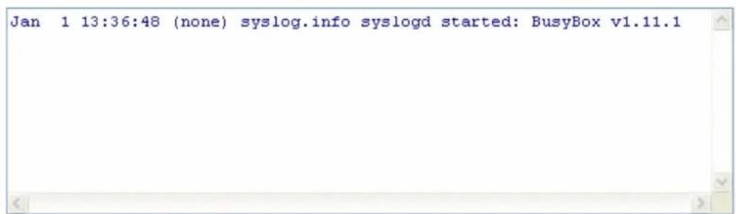
text_image
Jan 1 13:36:48 (none) syslog.info syslogd started: BusyBox v1.11.1
3
The system events will be displayed in this page, and here are descriptions of every buttons:
Save (1): Save current event log to a text file.
Clear (2): Delete all event logs displayed here.
Refresh (3): Refresh the event log display.
3.4.5. Security Log
All information about network and system security is kept here, and you can use this function to check the security event log of your router.
Please click 'Security Log' menu on the left of web management interface, and the following message will be displayed on your web browser:
Security Log 2
View any attempts that have been made to illegally gain access to your network.
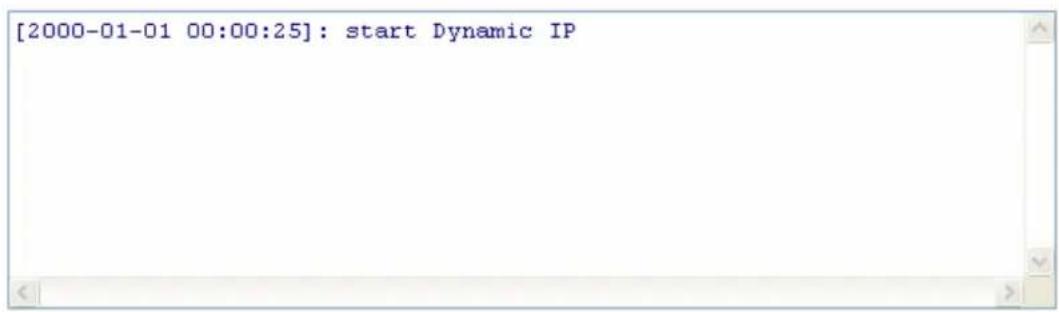
text_image
[2000-01-01 00:00:25]: start Dynamic IP
3
The system events will be displayed in this page, and here are descriptions of every buttons:
Save (1): Save current event log to a text file.
Clear (2): Delete all event logs displayed here.
Refresh (3): Refresh the event log display.
3.4.6. Active DHCP Client List
If you're using the DHCP server function of this router, you can use this function to check all active DHCP leases issued by this router.
Please click 'Active DHCP client' menu on the left of web management interface, and the following message will be displayed on your web browser:
Active DHCP Client 2
This table shows the assigned IP address, MAC address and time expired for each DHCP leased client.
| IP Address | MAC Address | Time Expired(s) |
| 192.168.1.100 | 00:1d:60:b8:14:be | forever |
Refresh
All information about active DHCP leases issued by this router will be displayed here. You can click 'Refresh' button to display latest information.
3.4.7. Statistics
You can use this function to check the statistics of wireless, LAN, and WAN interface of this router.
Please click 'Statistics' menu on the left of web management interface, and the following message will be displayed on your web browser:
Statistics 2
This page shows the packet counters for transmission and reception regarding to networks.
Refresh
| Wireless LAN | Sent Packets | 6 |
| Received Packets | 462 | |
| Ethernet LAN | Sent Packets | 6980 |
| Received Packets | 7228 | |
| Ethernet WAN | Sent Packets | 4956 |
| Received Packets | 0 |
You can click 'Refresh' button to display latest information.
3.5. Configuration Backup and Restore
You can backup all configurations of this router to a file, so you can make several copied of router configuration for security reason.
To backup or restore router configuration, please follow the following instructions:
Please click 'Tool' located at the upper-right corner of web management interface, then click 'Configuration Tools' on the left of web management interface, then the following message will be displayed on your web browser:
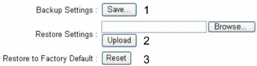
text_image
Backup Settings : Save... 1 Restore Settings : Browse... Upload 2 Restore to Factory Default : Reset 3Here are descriptions of every buttons:
Backup Press 'Save' button, and you'll be prompted to
Settings (1): download the configuration as a file, default filename is 'config.bin', you can save it as another filename for different versions, and keep it in a safe place.
Restore Press 'Browse...' to pick a previously-saved
Settings (2): configuration file from your computer, and then click 'Upload' to transfer the configuration file to router. After the configuration is uploaded, the router's configuration will be replaced by the file you just uploaded.
Restore to Click this button to remove all settings
Factory Default (3): you made, and restore the configuration of this router back to factory default settings.
3.6. Firmware Upgrade
The system software used by this router is called as 'firmware', just like any applications on your computer, when you replace the old application with a new one; your computer will be equipped with new function. You can also use this firmware upgrade function to add new functions to your router, even fix the bugs of this router.
To upgrade firmware, please follow the following instructions:
Please click 'Tool' located at the upper-right corner of web management interface, then click 'Firmware Upgrade' on the left of web management interface, then the following message will be displayed on your web browser:
The system will automatically reboot the router after you finished the firmware upgrade process. If you don't complete the firmware upgrade process in the "next" step, you have to reboot the router.
Next
Please click 'Next', and the following message will be displayed:
Firmware Upgrade
This tool allows you to upgrade the Broadband router's system firmware.
Enter the path and name of the upgrade file and then click the APPLY button below. You will be prompted to confirm the upgrade.
Browse...
Apply
Cancel
Click 'Browse' button first, you'll be prompted to provide the filename of firmware upgrade file. Please download the latest firmware file from our website, and use it to upgrade your router.
After a firmware upgrade file is selected, click 'Apply' button, and the router will start firmware upgrade procedure automatically. The procedure may take several minutes, please be patient.
NOTE: Never interrupt the upgrade procedure by closing the web browser or physically disconnect your computer from router. If the firmware you uploaded is corrupt, the firmware upgrade will fail, and you may have to return this router to the dealer of purchase to ask for help. (Warranty voids if you interrupted the upgrade procedure).
3.7. System Reset
If you think the network performance is bad, or you found the behavior of the router is strange, you can perform a router reset, sometime it will solve the problem.
To do so, please click 'Tool' located at the upper-right corner of web management interface, then click 'Reset' on the left of web management interface, then the following message will be displayed on your web browser:
Reset?
In the event that the system stops responding correctly or stops functioning, you can perform a Reset. Your settings will not be changed. To perform the reset, click on the APPLY button below. You will be asked to confirm your decision. The Reset will be complete when the LED Power light stops blinking.
Apply
Cancel
Please click 'Apply' to reset your router, and it will be available again after few minutes, please be patient.
4
Appendix
4.1. Hardware Specification
- SoC + RF: Realtek RTL8196C + RTL8192CE
- Flash: 2MB
• SDRAM: 16MB
• WAN Port: 10/100M UTP Port x 1
• LAN Ports: 10/100M UTP Port x 4 - Antenna: 2dBi Dipole Fixed Antenna x 2 (2T2R Spatial Multiplexing MIMO configuration; 2 antennas are for signal transmitting and 2 antennas are for signal receiving)
• Power: 5VDC, 1A Switching Power Adapter
• Dimension: 30(H) x 157(W) x 127(D) mm - Transmit Power :
- 11n: 13dBm± 1.5dBm , 11g: 14dBm± 1.5dBm , 11b: 17dBm± 1.5dBm
• Temperature: 32\~104°F (0 \~ 40°C)
• Humidity: 10-90% (NonCondensing)
• Certification: FCC, CE
4.2. Troubleshooting
If you found the router is working improperly or stop responding to you, don't panic! Before you contact your dealer of purchase for help, please read this troubleshooting first. Some problems can be solved by you within very short time!
| Scenario Solution | |
| Router is not responding to me when I want to access it by web browserCan't get connected to Internet | Please check the connection of power cord and network cable of this router. All cords and cables should be correctly and firmly inserted to the router.If all LEDs on this router are off, please check the status of A/C power adapter, and make sure it's correctly powered.You must use the same IP address section which router uses.Are you using MAC or IP address filter? Try to connect the router by another computer and see if it works; if not, please restore your router to factory default settings (pressing ‘reset’ button for over 10 seconds).Set your computer to obtain an IP address automatically (DHCP), and see if your computer can get an IP address.If you did a firmware upgrade and this happens, contact your dealer of purchase for help.If all above solutions don’t work, contact the dealer of purchase for help.1. Go to ‘Status’ -> ‘Internet Connection’ menu, and check Internet connection status.2. Please be patient, sometime Internet is just that slow.3. If you connect a computer to Internet directly before, try to do that again, and check if you can get connected to Internet with your computer directly attached to the device provided by your Internet service provider.4. Check PPPoE / L2TP / PPTP user ID and password again.5. Call your Internet service provide and check if there's something wrong with their service.7. If you just can't connect to one or more website, but you can still use other internet services, please check URL/Keyword filter.8. Try to reset the router and try again later.9. Reset the device provided by your Internet service provider too.10. Try to use IP address instead of hostname. If you can use IP address to communicate with a remote server, but can't use hostname, please check DNS setting. |
| I can’t locate my router by my wireless client | 1. ‘Broadcast ESSID’ set to off?2. All two antennas are properly secured.3. Are you too far from your router? Try to get closer.4. Please remember that you have to input ESSID on your wireless client manually, if ESSID broadcast is disabled. |
| File download is very slow or breaks frequently | 1. Are you using QoS function? Try to disable it and try again.2. Internet is slow sometimes, being patient.3. Try to reset the router and see if it’s better after that.4. Try to know what computers do on your local network. If someone’s transferring big files, other people will think Internet is really slow.5. If this never happens before, call you Internet service provider to know if there is something wrong with their network. |
| I can’t log onto web management interface: password is wrong | 1. Make sure you’re connecting to the correct IP address of the router!2. Password is case-sensitive. Make sure the ‘Caps Lock’ light is not illuminated.3. If you really forget the password, do a hard reset. |
| Router become hot 1. This is not a malfunction, if you can keep your hand on the router's case.2. If you smell something wrong or see the smoke coming out from router or A/C power adapter, please disconnect the router and A/C power adapter from utility power (make sure it's safe before you're doing this!), and call your dealer of purchase for help. | |
| The date and time of all event logs are wrong | Adjust the internal clock of router. |
4.3. Glossary
Default Gateway (Router): Every non-router IP device needs to configure a default gateway's IP address. When the device sends out an IP packet, if the destination is not on the same network, the device has to send the packet to its default gateway, which will then send it out towards the destination.
DHCP: Dynamic Host Configuration Protocol. This protocol automatically gives every computer on your home network an IP address.
DNS Server IP Address: DNS stands for Domain Name System, which allows Internet servers to have a domain name (such as www.Broadbandrouter.com) and one or more IP addresses (such as 192.34.45.8). A DNS server keeps a database of Internet servers and their respective domain names and IP addresses, so that when a domain name is requested (as in typing "Broadbandrouter.com" into your Internet browser), the user is sent to the proper IP address. The DNS server IP address used by the computers on your home network is the location of the DNS server your ISP has assigned to you.
DSL Modem: DSL stands for Digital Subscriber Line. A DSL modem uses your existing phone lines to transmit data at high speeds.
Ethernet: A standard for computer networks. Ethernet networks are connected by special cables and hubs, and move data around at up to 10/100 million bits per second (Mbps).
Idle Timeout: Idle Timeout is designed so that after there is no traffic to the Internet for a pre-configured amount of time, the connection will automatically be disconnected.
IP Address and Network (Subnet) Mask: IP stands for Internet Protocol. An IP address consists of a series of four numbers separated by periods, which identifies a single, unique Internet computer host in an IP network. Example: 192.168.1.254. It consists of 2 portions: the IP network address, and the host identifier.
The IP address is a 32-bit binary pattern, which can be represented as four cascaded decimal numbers separated by “.”: aaa.aaa.aaa.aaa, where each “aaa” can be anything from 000 to 255, or as four cascaded binary numbers separated by “.”: bbbbbbbb.bbbbbbbb.bbbbbbbb.bbbbbbbb, where each “b” can either be 0 or 1.
A network mask is also a 32-bit binary pattern, and consists of consecutive leading
1's followed by consecutive trailing 0's, such as
1111111.1111111.1111111.00000000. Therefore sometimes a network mask can also be described simply as "x" number of leading 1's.
When both are represented side by side in their binary forms, all bits in the IP address that correspond to 1's in the network mask become part of the IP network address, and the remaining bits correspond to the host ID.
For example, if the IP address for a device is, in its binary form,
11011001.10110000.10010000.00000111, and if its network mask is,
11111111.11111111.11110000.00000000
It means the device's network address is
11011001.10110000.10010000.00000000, and its host ID is,
00000000.00000000.00000000.00000111. This is a convenient and efficient method for routers to route IP packets to their destination.
ISP Gateway Address: (see ISP for definition). The ISP Gateway Address is an IP address for the Internet router located at the ISP's office.
ISP: Internet Service Provider. An ISP is a business that provides connectivity to the Internet for individuals and other businesses or organizations.
LAN: Local Area Network. A LAN is a group of computers and devices connected together in a relatively small area (such as a house or an office). Your home network is considered a LAN.
MAC Address: MAC stands for Media Access Control. A MAC address is the hardware address of a device connected to a network. The MAC address is a unique identifier for a device with an Ethernet interface. It is comprised of two parts: 3 bytes of data that corresponds to the Manufacturer ID (unique for each manufacturer), plus 3 bytes that are often used as the product's serial number.
NAT: Network Address Translation. This process allows all of the computers on your home network to use one IP address. Using the broadband router's NAT capability, you can access the Internet from any computer on your home network without having to purchase more IP addresses from your ISP.
Port: Network Clients (LAN PC) uses port numbers to distinguish one network application/protocol over another. Below is a list of common applications and protocol/port numbers:
| Application | Protocol | Port Number |
| Telnet | TCP | 23 |
| FTP | TCP | 21 |
| SMTP | TCP | 25 |
| POP3 | TCP | 110 |
| H.323 | TCP | 1720 |
| SNMP | UCP | 161 |
| SNMP Trap UDP 162 | ||
| HTTP | TCP | 80 |
| PPTP | TCP | 1723 |
| PC Anywhere | TCP 5631 | |
| PC Anywhere | UDP | 5632 |
PPPoE: Point-to-Point Protocol over Ethernet. Point-to-Point Protocol is a secure data transmission method originally created for dial-up connections; PPPoE is for Ethernet connections. PPPoE relies on two widely accepted standards, Ethernet and the Point-to-Point Protocol. It is a communications protocol for transmitting information over Ethernet between different manufacturers
Protocol: A protocol is a set of rules for interaction agreed upon between multiple parties so that when they interface with each other based on such a protocol, the interpretation of their behavior is well defined and can be made objectively, without confusion or misunderstanding.
Router: A router is an intelligent network device that forwards packets between different networks based on network layer address information such as IP addresses.
Subnet Mask: A subnet mask, which may be a part of the TCP/IP information provided by your ISP, is a set of four numbers (e.g. 255.255.255.0) configured like an IP address. It is used to create IP address numbers used only within a particular network (as opposed to valid IP address numbers recognized by the Internet, which must be assigned by InterNIC).
TCP/IP, UDP: Transmission Control Protocol/Internet Protocol (TCP/IP) and Unreliable Datagram Protocol (UDP). TCP/IP is the standard protocol for data transmission over the Internet. Both TCP and UDP are transport layer protocol. TCP performs proper error detection and error recovery, and thus is reliable. UDP on the other hand is not reliable. They both run on top of the IP (Internet Protocol), a network layer protocol.
WAN: Wide Area Network. A network that connects computers located in geographically separate areas (e.g. different buildings, cities, countries). The Internet is a wide area network.
Web-based Management Graphical User Interface (GUI): Many devices support a graphical user interface that is based on the web browser. This means the user can use the familiar Netscape or Microsoft Internet Explorer to Control/configure or monitor the device being managed.